

Page 1

LCD TV
PLASMA TV
OWNER’S MANUAL
LCD TV MODELS
32LG6
***
37LG6
***
42LG6
***
47LG6
***
42LG7
***
47LG7
***
52LG7
***
32LG8
***
42LG8
***
PLASMA TV MODELS
50PG3
***
42PG6
***
50PG6
***
60PG6
***
50PG7
***
60PG7
***
Please read this manual carefully before operating your set.
Retain it for future reference.
Record model number and serial number of the set.
Refer to the label on the back cover and quote this
information.
To your dealer when requiring service.
ENGLISH
Page 2

Page 3
1
ACCESSORIES
ACCESSORIES
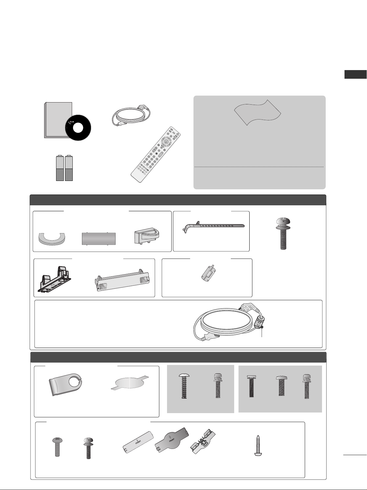
Ensure that the following accessories are included with your TV.
If an accessory is missing, please contact the dealer where you purchased the product.
■
Image shown may differ from your TV.
Owner's
Manual
Owner’s manual
Owner’s Manual
Batteries
M
U
T
E
R
E
T
U
R
N
A
V
M
O
D
E
F
AV
TV
I
N
P
U
T
STB
P
O
W
E
R
Q. M
E
NU
M
E
N
U
O
K
P
123
456
78
0
9
LIST
Q.VIEW
DVD
T
I
M
E
S
I
Z
E
U
P
D
A
T
E
REVEAL
I
N
D
E
X
H
O
L
D
T
E
X
T
P
I
P
Remote Control
Power Cord
Polishing Cloth
Polishing cloth for use on the screen
This feature is not available for all models.
*Lightly wipe any stains or fingerprints on the
surface of the TV with the polishing cloth.
Do not use excessive force. This may
cause scratching or discolouration.
LLCCDD TTVV mmooddeellss
Cable management clip
(Refer to p.15)
PPLLAASSMMAA TTVV mmooddeellss
(only 50/60PG6
***
,
50/60PG7
***
)
Protection cover
(Refer to p.12)
32LG6
***
: 3EA
37 LG 6
***
: 4EA
(only 32/37LG6
***
)
4EA
2EA
(only 42LG6
***
)
4EA
1EA
bolts for stand assembly (Refer to p. 11)
4-bolts for stand assembly
Refer to p. 10
(only 42PG6
***
)
(only 50PG3
***
)
or
42PG6
***
: 1EA
50PG3
***
: 2EA only
Cable management clip
protection cover
(Refer to p.10)
Cable Holder
Only 32/37/42/47LG6
***
Only 42/47/52LG7
***
, 32/42LG8
***
Bolts for stand assembly
(Refer to p.12)
x 4
x 4
(42LG7
***
, 32/42LG8
***
only)
(except
50PG3
***
)
1-screw for stand fixing
(Refer to p.9)
(32/42LG8
***
only)
Protection cover
or
Ferrite core can be used to reduce the electromagnetic
wave when connecting the power cord.
The closer the location of the ferrite core to the power
plug, the better it is.
Install the power plug closely.
or
This feature is not available for
all models.
Ferrite Core
Use of ferrite core (
This feature is not available for all models.
)
Page 4

2
CONTENTS
CONTENTS
Watching PIP(Picture-in-Picture).............................63
Picture Size (Aspect Ratio)Control.........................64
Preset Picture Settings
- Picture Mode-Preset............................................66
- Auto Colour Tone Control(Cool/Medium/Warm)
67
Manual Picture Adjustment
- Picture Mode-User Option................................68
- Colour Tone - User Option...............................69
-
Picture Improvement Technology
...................70
Advanced - Gamma......................................................71
Advanced - Film Mode/Real Cinema.......................72
Advanced - Black(Darkness) Level...........................73
Eye Care..........................................................................74
Advanced-TruMotion ...................................................75
Picture Reset..................................................................76
TruMotion Demo ..........................................................77
Power Indicator..............................................................78
Image Sticking Minimization(ISM) Method...........79
Power Saving Picture Mode.......................................80
Factory Reset .................................................................81
Remote Control Key Functions..................................38
Turning on the TV....................................................... 40
Programme Selection ................................................. 40
Volume Adjustment......................................................40
Quick Menu................................................................... 41
On Screen Menus Selection and Adjustment ......42
Auto Programme Tuning............................................ 43
Manual Programme Tuning....................................... 44
Fine Tuning .....................................................................45
Assigning a Station Name ..........................................46
Booster............................................................................47
Programme Edit ........................................................... 48
PICTURE CONTROL
WATCHING TV / PROGRAMME CONTROL
AACCCCEESSSSOORRIIEESS
.....................................................1
Front Panel Controls................................................. 4
Back Panel Information ............................................ 7
Attaching the TV to a desk ..................................... 9
Stand Installation..................................................... 10
Back Cover for Wire Arrangement....................... 13
Please set it up carefully so the product
does not fall over. .....................................................16
Desktop Pedestal Installation ............................... 17
Wall Mount: Horizontal installation..................... 17
Antenna Connection............................................... 18
PREPARATION
EXTERNAL EQUIPMENT SETUP
HD Receiver Setup .......................................................19
DVD Setup.................................................................... 22
VCR Setup..................................................................... 25
Other A/V Source Setup .......................................... 28
External Stereo............................................................. 29
AV Output Setup ........................................................ 30
PC Setup .........................................................................31
- Screen Setup for PC Mode................................34
When connecting the USB device...........................55
Photo List........................................................................56
Music List........................................................................58
Movie List
.........................................................................60
Divx Registration Code
...................................................62
TO USE THE USB DEVICE
Favourite Programme.................................................. 49
Selecting the Programme List.................................. 50
.................................................................. 51
Key lock.......................................................................... 53
AV Mode.........................................................................54
Page 5

3
CONTENTS
SOUND & LANGUAGE CONTROL
Auto Volume Leveler....................................................82
Preset Sound Settings - Sound Mode....................83
Sound Setting Adjustment - User Mode ...............84
Balance............................................................................85
TV Speakers On/Off Setup .......................................86
Selecting Audio Out ....................................................86
Sliding Mode..................................................................87
I/II
- Stereo/Dual Reception....................................... 88
- NICAM Reception ....................................................... 89
- Speaker Sound Output Selection.................... 89
On-Screen Menu Language Selection
...................... 90
APPENDIX
Troubleshooting............................................................98
Maintenance ...............................................................100
Product Specifications ..............................................101
Programming the Remote Control ...................... 103
IR Codes ..................................................................... 105
External Control Through RS-232C ................... 107
TIME SETTING
Clock Setup....................................................................91
Auto On/Off Timer Setting .......................................92
Sleep Timer Setting......................................................93
Auto Shut-off Setting ..................................................94
TELETEXT
Switch On/Off .............................................................95
SIMPLE Text....................................................................95
TOP Text.........................................................................96
FASTEXT.........................................................................96
Special Teletext Functions..........................................97
Page 6
4
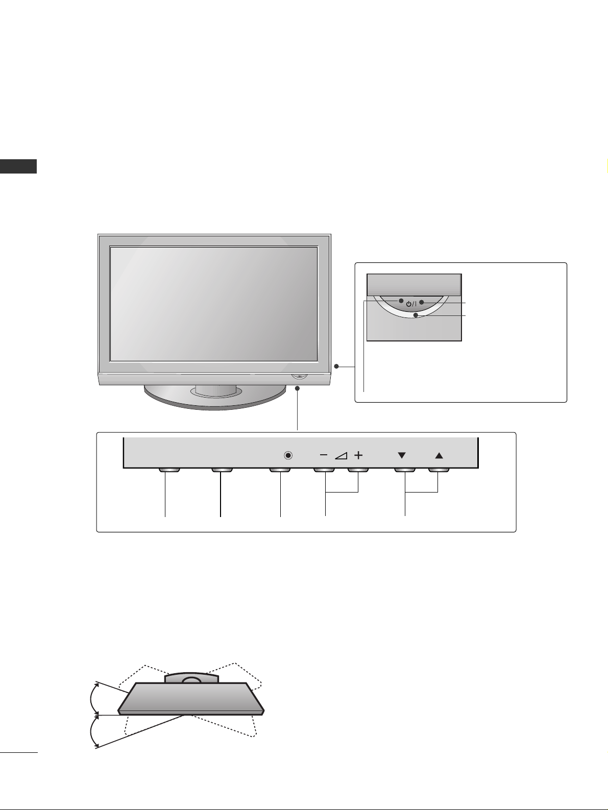
FRONT PANEL CONTROLS
PREPARATION
PREPARATION
■
This is a simplified representation of the front panel. Image shown may differ from your TV.
■
If your product has a protection film attached, remove the film and then wipe the product with a polishing
cloth.
Plasma TV Models
Remote Control Sensor
POWER
Power/Standby Indicator
• illuminates red in standby mode.
• illuminates green when the TV is
switched on.
PROGRAMMEVOLUMEMENU OKINPUT
OKOK
MENUMENU
INPUTINPUT
P
Swivel Stand
This feature is not available for all models.
After installing the TV, you can adjust the TV set manually to the left or right direction by 20 degrees to suit
your viewing position.
Page 7
5
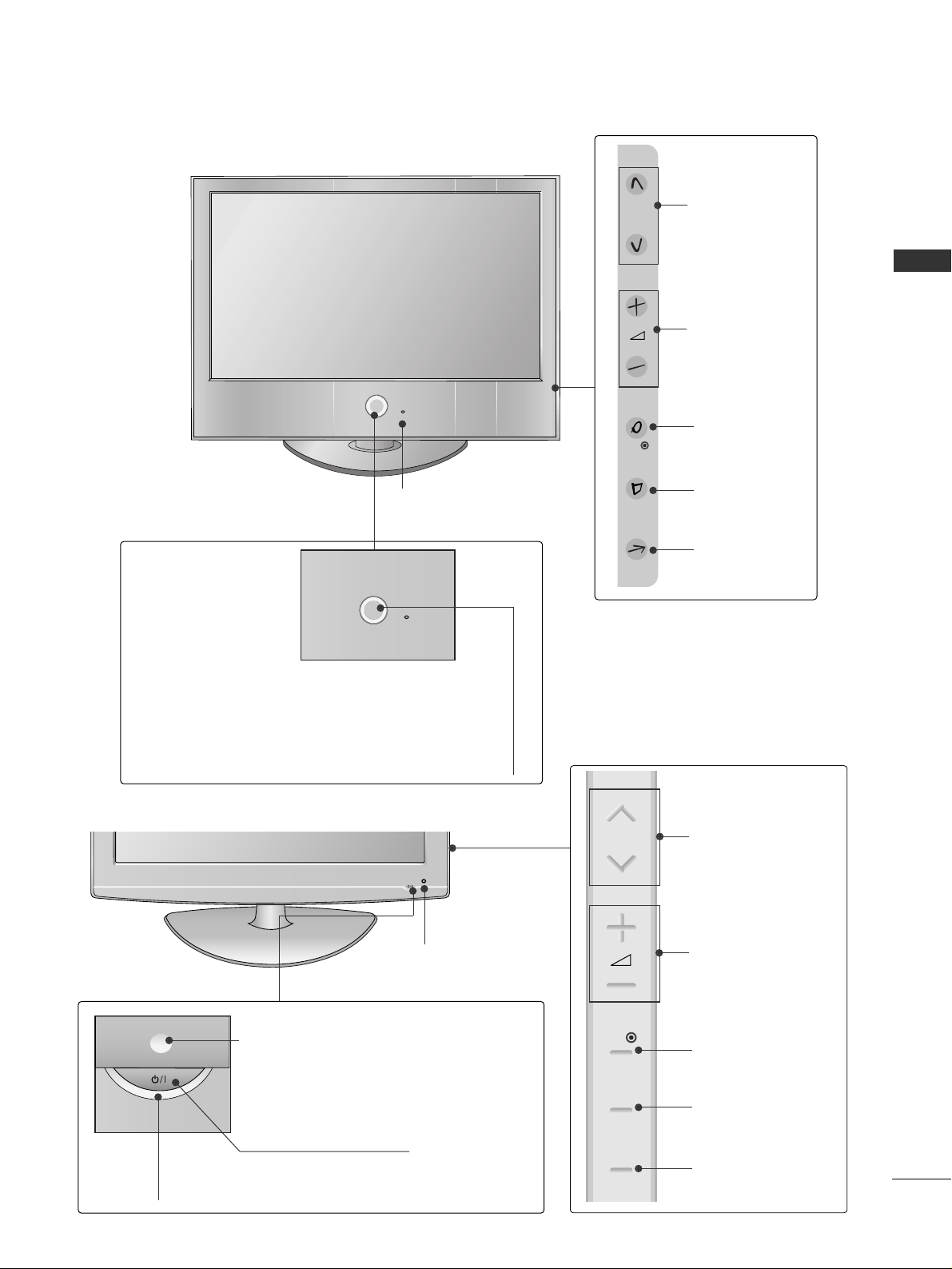
PREPARATION
32/37/42/47LG6
***
OK
P
MENU
INPUT
PROGRAMME
VOLUME
OK
MENU
INPUT
Intelligent Sensor
Adjusts picture according to the
surrounding conditions
POWER
Remote Control Sensor
Power/Standby Indicator
• illuminates red in standby mode.
• illuminates White when the TV is switched on.
Note:
You can adjust Power Indicator in the Option menu.
POWER
Power/Standby Indicator
• illuminates red in standby mode.
• illuminates blue when the TV is switched on.
Note:
You can adjust
PPoowweerr IInnddiiccaattoorr
in the
Option menu.
PROGRAMME
VOLUME
OK
MENU
INPUT
Intelligent Sensor
Adjusts picture according to the
surrounding conditions.
Remote Control Sensor
42/47/52LG7
***
LCD TV Models
P
OK
MENU
INPUT
Page 8

6
PREPARATION
32/42LG8
***
PROGRAMME
VOLUME
MENU OK
INPUT
POWER
OK
MENU
INPUT
P
Remote Control Sensor
Power/Standby Indicator
• illuminates red in standby mode.
• illuminates blue when the TV is switched on.
Note:
You can adjust
PPoowweerr IInnddiiccaattoorr
in
the
Option menu.
Not Using the Desk-type Stand
■
Image shown may differ from your TV.
When installing the wall-mounted unit, use the
protection cover for desk-type stand installation.
Insert the
PPRROOTT EECCTT IIOONN CCOOVVEERR
into the TV
until clicking sound.
32LG8
***
How to remove the portection cover
■
Image shown may differ from your TV.
Press the A part of protection cover as shown and
pull it backward.
32LG8
***
A
* Give extra space for installing speakers on both sides of the TV to allow for free movement.
(only 42LG8***)
Page 9
7
PREPARATION
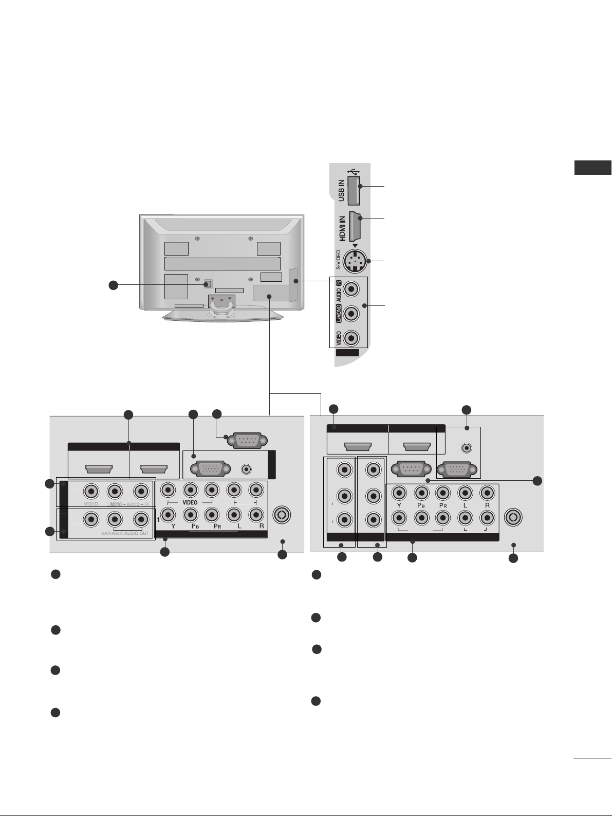
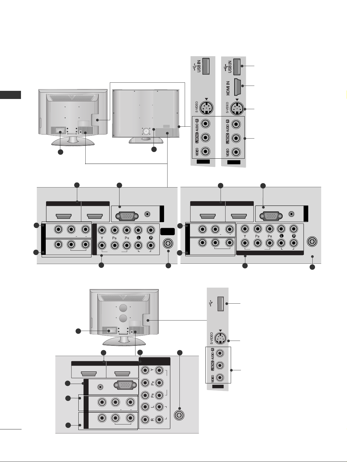
BACK PANEL INFORMATION
■
This is a simplified representation of the back panel. Image shown may differ from your TV.
Plasma TV Models
HDMI IN HDMI/DVI IN
12
AUDIO
(RGB/DVI)
RGB
(PC)
N
COMPO
N
ANTENNA
IN
RS-232C IN
(CONTROL)
O
AV IN 2
MONO
AUDIO
VIDEO
OU
VARIABLE AUDIO OUT
1
5
6
HDMI Input
Connect a HDMI signal to HDMI IN.
Or DVI(VIDEO)signal to HDMI/DVI port with DVI
to HDMI cable.
RGB/Audio Input
Connect the monitor output from a PC to the
appropriate input port.
Audio/Video Input (AV IN 1)
Connect audio/video output from an external
device to these jacks.
AV Output
Connect second TV or monitor to the AV OUT
socket on the
TV.
Variable Audio Output
Connect an external amplifier or add a subwoofer
to your surround sound system.
Component Input
Connect a component video/audio device to
these jacks.
Antenna Input
Connect RF antenna to this jack.
Power Cord Socket
This TV operates on an AC power. The voltage is
indicated on the Specifications page. Never
attempt to operate the TV on DC power.
RS-232C Input
(CONTROL) Port
Connect the serial port of the control devices to
the RS-232C jack.
(This feature is not available for all models.)
1
2
3
4
5
6
7
8
2
8
3
AV IN 2
L/
MONO
AUDIO
VIDEO
VARIABLE AUDIO OUT
VIDEO
1
2
4
3 4
8
5
6
42/50/60PG6
***
50PG3
***,
50/60PG7
***
7
AV IN 2
USB Input
HDMI Input
Connect a HDMI signal to
HDMI IN.
S-Video Input
Connect S-Video out
from an S-VIDEO device.
Audio/Video Input
Connect audio/video
output from an external
device to these jacks.
T
NENT I
AUDI
B I
3
AV IN 2
12
VIDEO
MONO
L/
AUDIO
R
AV IN 1
AV O UT
HDMI IN HDMI/DVI IN
RS-232C IN
VIDEO
VARIABLE AUDIO OUT
(CONTROL)
2
1
RGB IN
VIDEO
COMPONENT IN
AUDIO
(RGB/DVI)
(PC)
AUDIO
ANTENNA
IN
Page 10
8
PREPARATION
HDMI IN HDMI/DVI IN
1
1
2
2
AUDIO
RGB
(PC)
RGB IN
COMPONENT IN
AUDIO
VIDEO
(RGB/DVI)
L/L/MONOMONO
R
AUDIOAUDIO
AV
VIDEOVIDEO
IN 1
OUT
VARIABLE AUDIO OUTVARIABLE AUDIO OUT
AV IN 2
ANTENNA
IN
AV IN 2
12
L/ MONO
R
AUDIO
VIDEO
VARIABLE
AUDIO OUT
2
1
5
LCD TV Models
6
42/47LG6
***
, 42/47/52LG7
***
32/37LG6
***
3
4
AV IN 2
HDMI IN HDMI/DVI IN
1
1
2
2
AUDIO
RGB
(PC)
RGB IN
COMPONENT IN
AUDIO
VIDEO
(RGB/DVI)
L/L/MONOMONO
R
AUDIOAUDIO
AV
VIDEOVIDEO
IN 1
OUT
VARIABLE VARIABLE
AUDIO OUTAUDIO OUT
ANTENNA
IN
2
1
5
6
3
4
42/47/52LG7
***
32/37/42/47LG6
***
7
7
USB Input
HDMI Input
Connect a HDMI signal
to HDMI IN.
S-Video Input
Connect S-Video out
from an S-VIDEO device.
Audio/Video Input
Connect audio/video
output from an external
device to these jacks.
PREPARATION
HDMI IN HDMI/DVI IN
12
ANTENNA
IN
1
2
VIDEO
AUDIO
RGB
(PC)
RGB IN
(RGB/DVI)
AUDIO
AV
L(L(MONO)MONO)
R
AUDIOAUDIO
VIDEOVIDEO
IN1
OUT
VARIABLE AUDIO OUTVARIABLE AUDIO OUT
COMPONENT
IN
32/42LG8
***
OK
MENU
INPUT
P
AV IN 2
3
4
1
5
2
6
USB Input
S-Video Input
Connect S-Video out
from an S-VIDEO device.
Audio/Video Input
Connect audio/video
output from an external
device to these jacks.
7
3
AV IN 2
AV IN 2
USB IN
AV IN 2
Page 11
9
PREPARATION
HDMI Input
Connect a HDMI signal to HDMI IN.
Or DVI(VIDEO)signal to HDMI/DVI port with DVI
to HDMI cable.
(HDMI IN 3 is available for 42/47LG6
***
,
42/47/52LG7
***
)
RGB/Audio Input
Connect the monitor output from a PC to the
appropriate input port.
Audio/Video Input
Connect audio/video output from an external
device to these jacks.
AV Output
Connect second TV or monitor to the AV OUT
socket on the TV.
Variable Audio Output
Connect an external amplifier or add a subwoofer
to your surround sound system.
Component Input
Connect a component video/audio device to
these jacks.
Antenna Input
Connect RF antenna to this jack.
Power Cord Socket
This TV operates on an AC power. The voltage is
indicated on the Specifications page. Never
attempt to operate the TV on DC power.
1
2
3
4
5
6
7
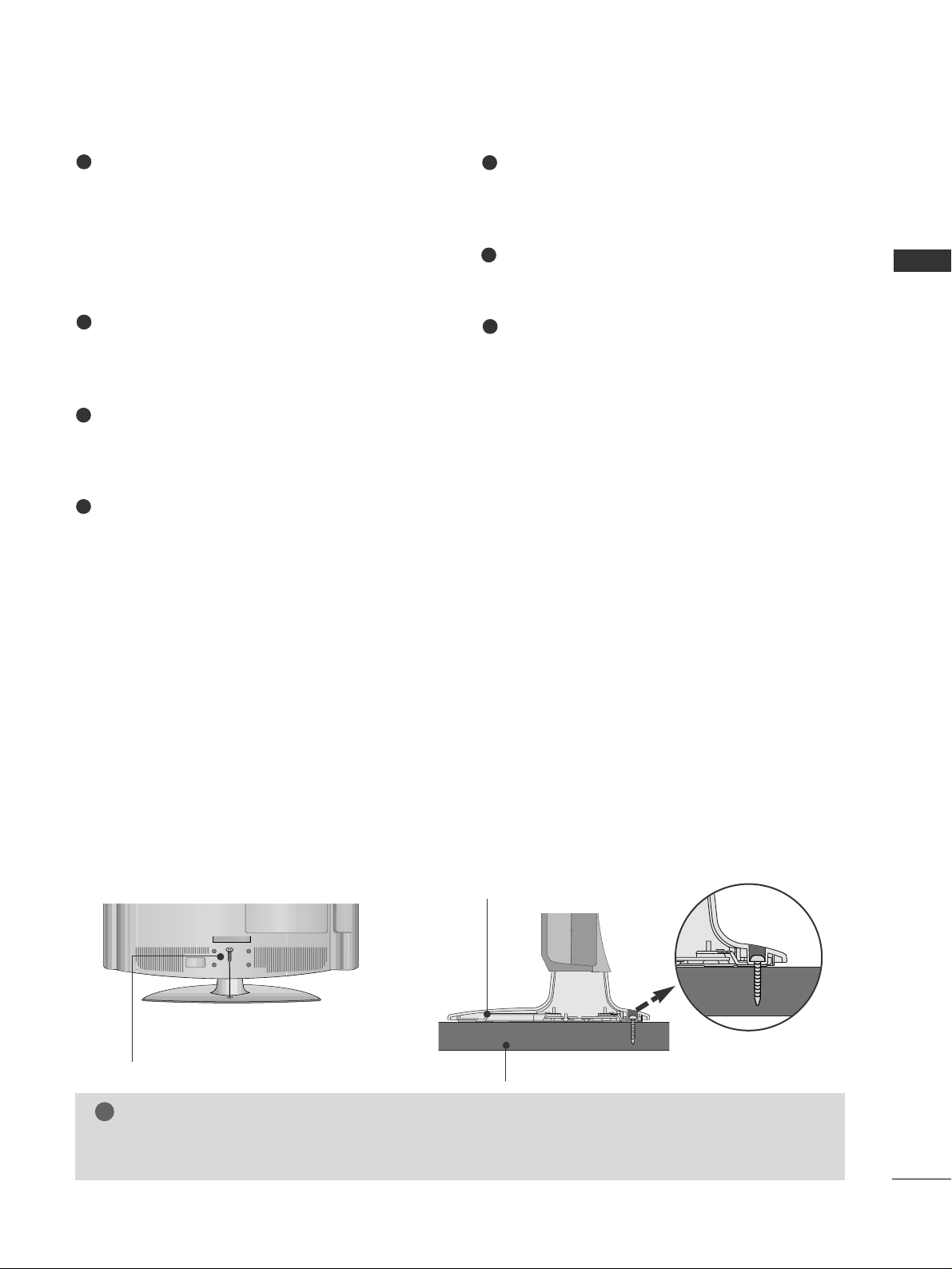
ATTACHING THE TV TO A DESK (Only 32/42LG8
***
)
The TV must be attached to desk so it cannot be pulled in a forward/backward direction, potentially causing
injury or damaging the product. Use only an attached screw.
1-Screw
(provided as parts of the product)
Desk
Stand
WARNING
!
G
To prevent TV from falling over, the TV should be securely attached to the floor/wall per installation
instructions. Tipping, shaking, or rocking the machine may cause injury.
Page 12
10
PREPARATION
PREPARATION
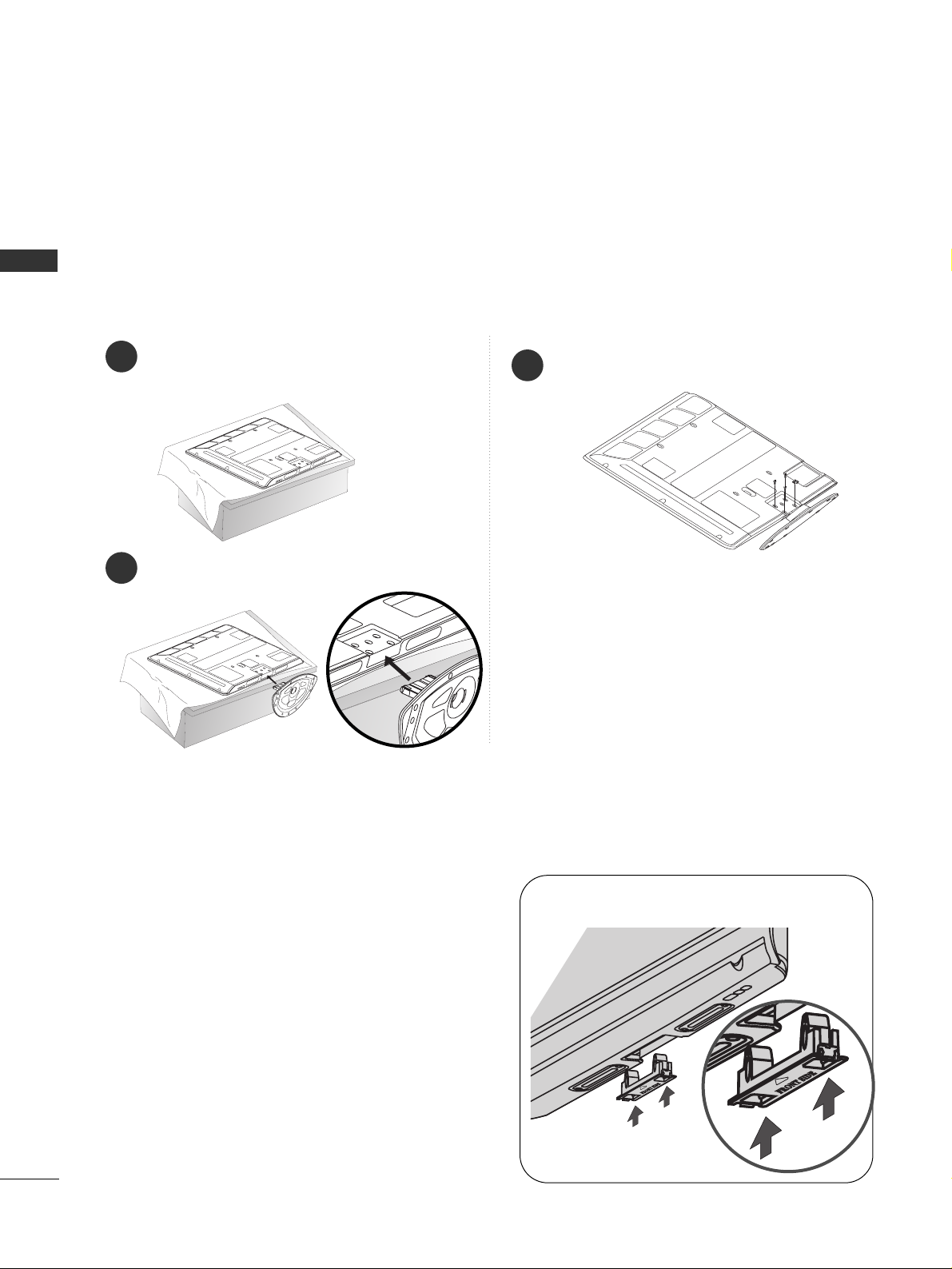
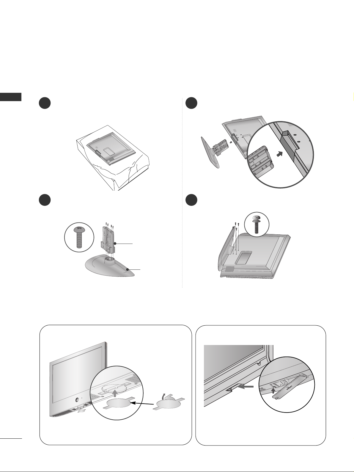
STAND INSTALLATION
■
Image shown may differ from your TV.
Carefully place the TV screen side down on a
cushioned surface to protect the screen from
damage.
Assemble the TV as shown.
Fix the 4 bolts securely using the holes in the
back of the TV.
1
2
3
only 42PG6
***
When assembling the desk type stand, check whether the bolt is fully tightened.
(If not tightened fully, the product can tilt forward after the product installation.) If you tighten the bolt with
excessive force, the bolt can deviate from abrasion of the tightening part of the bolt.
Plasma TV models
Not Using the Desk-type Stand
When installing the wall-mounted unit, use the
protection cover for desk-type stand installation.
Insert the PROTECTION COVER into the TV until
clicking sound.
■
Image shown may differ from your TV.
Page 13
11
PREPARATION
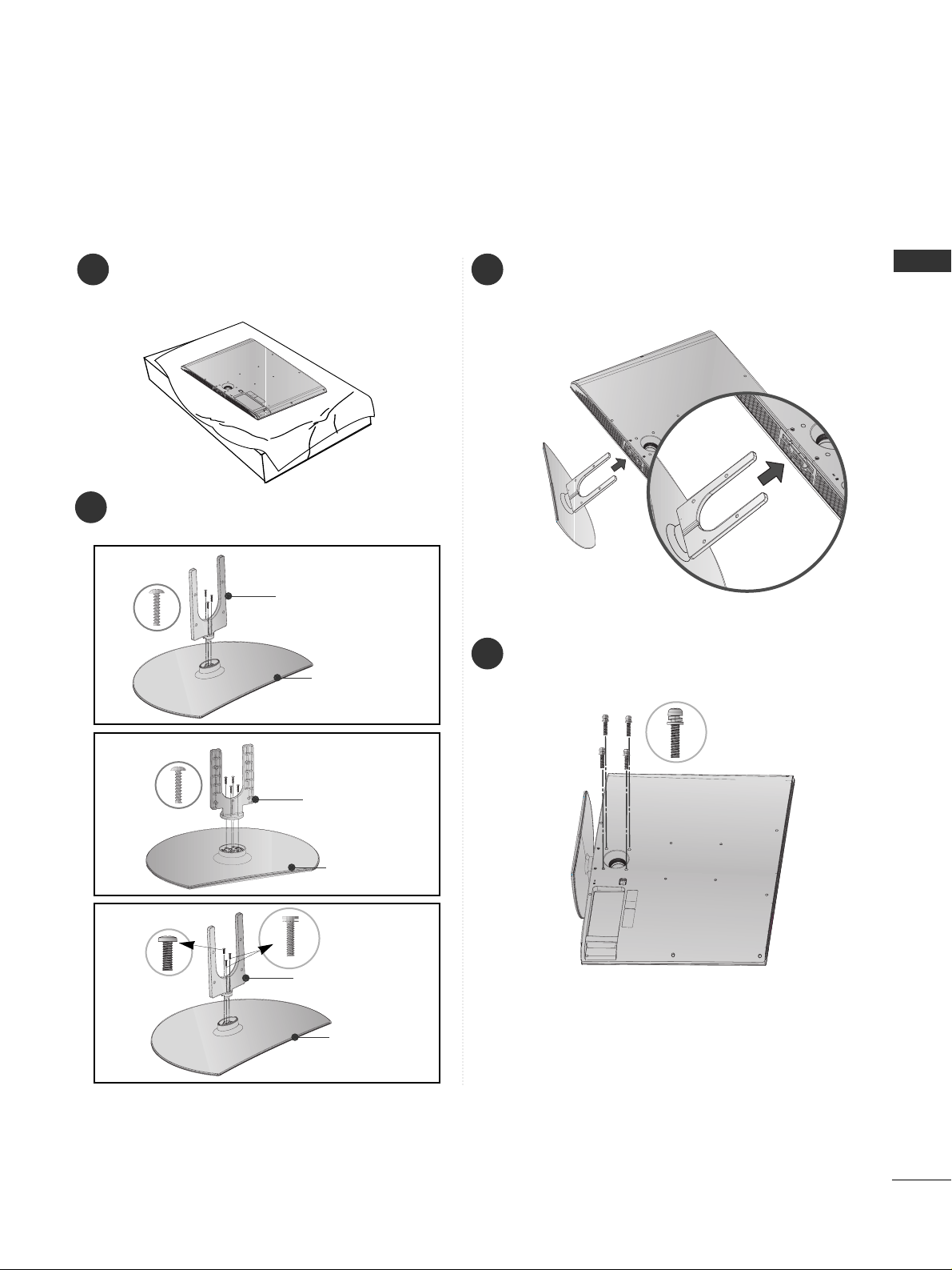
1 3
4
Carefully place the TV screen side down on a
cushioned surface to protect the screen from
damage.
2
Assemble the parts of the
SS ttaanndd BBoo ddyy
with
CCoovvee rr BB aassee
of the TV.
Assemble the TV as shown.
Fix the 4 bolts securely using the holes in the
back of the TV.
Stand Body
Cover Base
32LG6
***
37 LG 6
***
Stand Body
Cover Base
42LG6
***
Stand Body
Cover Base
only 32/37/42LG6
***
Page 14
12
PREPARATION
1 3
4
Carefully place the TV screen side down on a
cushioned surface to protect the screen from
damage.
2
Assemble the parts of the
SS ttaanndd BBoo ddyy
with
the
CCoovvee rr BB aassee
of the TV.
Assemble the TV as shown.
Fix the 4 bolts securely using the holes in the
back of the TV.
Stand Body
Cover Base
only 42LG7
***
, 32/42LG8
***
Not Using the Desk-type Stand
When installing the wall-mounted unit, use the protection cover for desk-type stand installation.
After removing the protection paper from the
protection cover, adhere it to the TV as shown.
■
Image shown may differ from your TV.
Insert the
PPRROO TTEECCTTIIOONN CCOOVVEERR
into the TV
until clicking sound.
42/47/52LG7
***
, 42LG8
***
32/37/42/47LG6
***
Page 15

13
PREPARATION
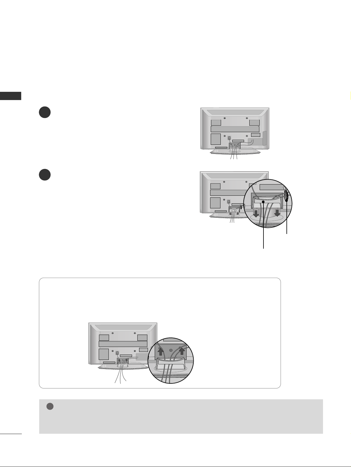
BACK COVER FOR WIRE ARRANGEMENT
Connect the cables as necessary.
To connect additional equipment, see the
EExxttee rrnnaall EEqquuii ppmmee nntt SS eett uu pp
section.
1
Install the
CCAABBLLEE MMAANNAAGGEEMMEENNTT CCLLIIPP
as shown.
2
Hold the
CCAA BB LL EE MMAA NNAAGGEEMMEENN TT CCLLIIPP
with both hands and pull it upward.
NOTE
!
GG
Do not use the CABLE MANAGEMENT CLIP to lift the TV.
- If the TV is dropped, you may be injured or the TV may be damaged.
How to remove the cable management clip
■
Image shown may differ from your TV.
CABLE MANAGEMENT CLIP
Connect the cables as necessary.
To connect additional equipment, see the
EExxttee rrnnaall EEqquuii ppmmee nntt SS eett uu pp
section.
1
Install the
CCAABBLLEE MMAANNAAGGEEMMEENNTT CCLLIIPP
as shown.
2
CABLE MANAGEMENT CLIP
42PG6
***
50/60PG6
***,
50/60PG7
***
50/60PG6
***,
50/60PG7
***
42PG6
***
Separate CABLE MANAGEMENT from TV by
pressing two latches.
* For the 42PG6*** model, press the center of the CABLE MANAGEMENT CLIP and then lift up it.
Fix the
CCaabbllee HHoo ll ddeerr
as shown and bundle
the cables.
Page 16
14
PREPARATION
PREPARATION
■
Image shown may differ from your TV.
How to remove the cable management clip
Connect the cables as necessary.
To connect additional equipment, see the
EXTERNAL EQUIPMENT SETUP section.
Install the CABLE MANAGEMENT CLIP as
shown.
If your TV has the CABLE HOLDER, install it
as shown and bundle the cables.
1
2
NOTE
!
GG
Do not use the CABLE MANAGEMENT CLIP to lift the TV.
- If the TV is dropped, you may be injured or the TV may be damaged.
Hold the
CCAA BB LL EE MMAANNAA GGEEMMEENNTT CCLLII PP
with both hands and pull it upward.
50PG3
***
CABLE MANAGEMENT CLIP
CABLE HOLDER
Page 17

15
PREPARATION
32/37/42/47LG6
***
Connect the cables as necessary.
To connect additional equipment, see the
EExxttee rrnnaall
EEqquuii ppmmee nntt SS eett uu pp
section.
1
2
Align the hole with the tab on the
CCAABBLLEE
MMAANNAA GGEEMMEENNTT CCLLIIPP
.
Turn the
CCAA BB LL EE MMAANNAA GGEEMMEENNTT CCLLII PP
as
shown.
Note: This cable management can be broken
by excessive pressure.
Connect the cables as necessary.
To connect additional equipment, see the
External Equipment Setup section of the manual.
1
Open the
CCAA BB LL EE MMAANNAA GGEEMMEENNTT CCLLII PP
as
shown and manage the cables.
2
CABLE MANAGEMENT CLIP
Fit the
CCAA BB LL EE MMAANNAA GGEEMMEENNTT CCLLII PP
as
shown.
3
42/47/52LG7
***
, 32/42LG8
***
Page 18
16
PREPARATION
PREPARATION
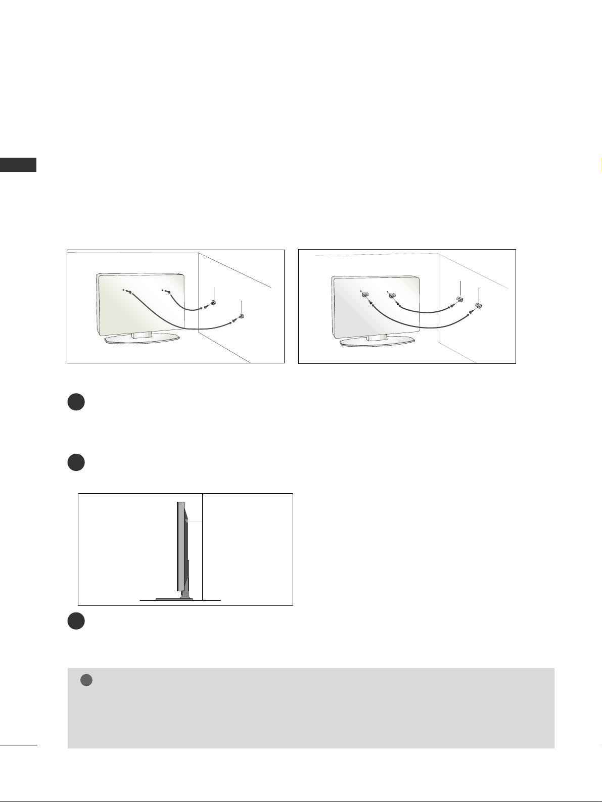
PLEASE SET IT UP CAREFULLY SO THE PRODUCT DOES NOT FALL OVER.
A
You should purchase necessary components to fix the TV to the wall on the market.
A
Position the TV close to the wall to avoid the possibility of it falling when pushed.
A
The instructions shown below are a safer way to
set
up the TV, which is to fix it to the wall, avoiding the
possibility of it falling forwards if pulled. This will prevent the TV from falling forward and causing injury.
This will also prevent the TV from damage. Ensure that children do not climb or hang from the TV.
NOTE
!
G
When moving the TV undo the cords first.
G
Use a platform or cabinet string and large enough to support the size and weight of the TV.
G
To use the TV safely make sure that the height of the bracket on the wall and on the TV is the same.
3
1
2
Use the eye-bolts or TV brackets/bolts to fix the product to the wall as shown in the picture.
(If your TV has bolts in the eyebolts, loosen then bolts.)
* Insert the eye-bolts or TV brackets/bolts and tighten them securely in the upper holes.
Secure the wall brackets with bolts to the wall.
Ensure that both brackets are even.
3
Use a strong cord to secure the TV.
Secure the cord in such a way that it becomes taught when the TV is in position.
2
1
2
1
Page 19

17
PREPARATION
■
The TV can be installed in various ways such as on a wall, or on a desktop etc.
■
The TV is designed to be mounted horizontally.
DESKTOP PEDESTAL INSTALLATION
For adequate ventilation allow a clearance of 4” (10cm) all around the TV .
4 inches
4 inches
4 inches
4 inches
Power Supply
Circuit breaker
EARTHING
Ensure that you connect the earth wire to prevent possible electric shock. If grounding methods are not possible,
have a qualified electrician install a separate circuit breaker.
Do not try to earth the TV by connecting it to telephone
wires, lightening rods or gas pipes.
WALL MOUNT: HORIZONTAL INSTALLATION
For adequate ventilation allow a clearance of 4” (10cm) all around the TV. We recommend that you
use a wall mounting bracket of LG brand when mounting the TV to a wall.
4 inches
4 inches
4 inches
4 inches
4 inches
Page 20
18
PREPARATION
ANTENNA
IN
AV IN 2
PREPARATION
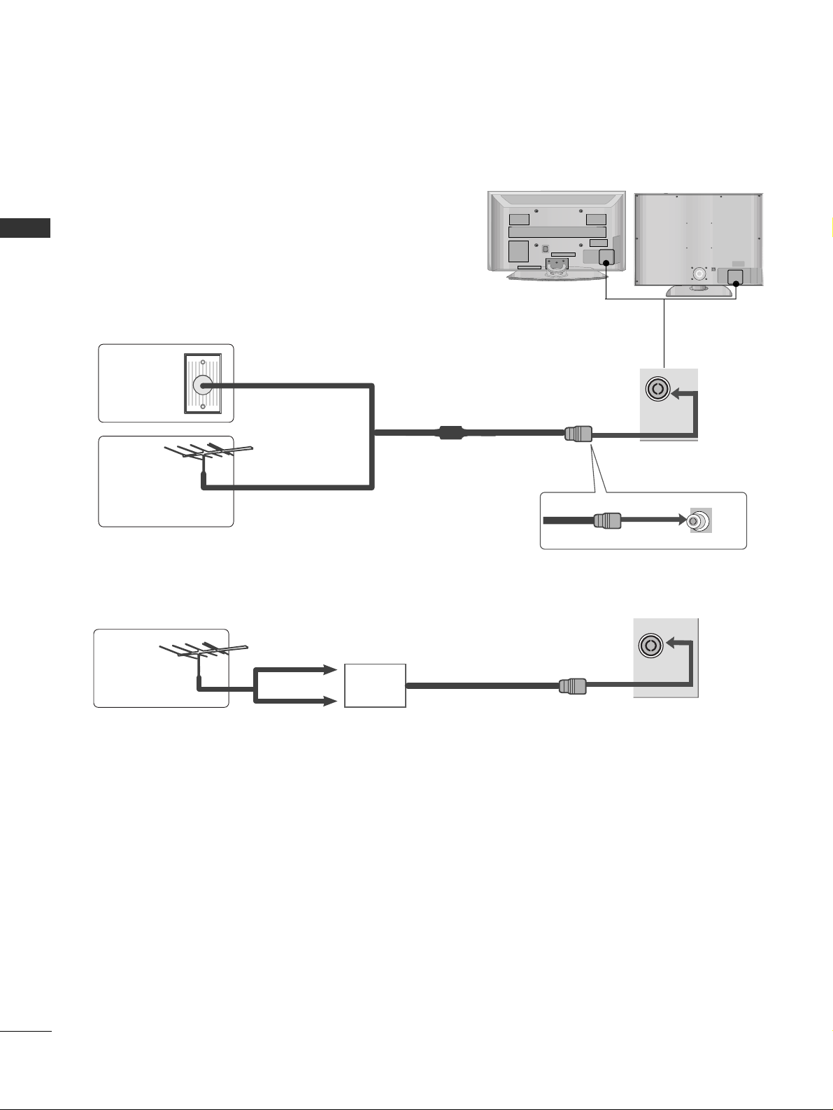
ANTENNA CONNECTION
■
For optimum picture quality, adjust antenna direction.
■
An antenna cable and converter are not supplied.
Multi-family Dwellings/Apartments
(Connect to wall antenna socket)
Single-family Dwellings /Houses
(Connect to wall jack for outdoor antenna)
Outdoor
Antenna
Wall
Antenna
Socket
RF Coaxial Wire (75 ohm)
Antenna
UHF
VHF
■
In poor signal areas, to achieve better picture quality it may be necessary to install a signal amplifier to the
antenna as shown above.
■
If signal needs to be split for two TVs, use an antenna signal splitter for connection.
■
To prevent damage do not connect to the mains outlet until all connections are made between the devices.
AV IN 2
Signal
Amplifier
ANTENNA
IN
Page 21
19
EXTERNAL EQUIPMENT SETUP
HDMI IN HDMI DVI IN
HDMI/DVI IN
1
1
2
COMPONENT IN
VIDEO
AUDIO
1 2
EXTERNAL EQUIPMENT SETUP
HD RECEIVER SETUP
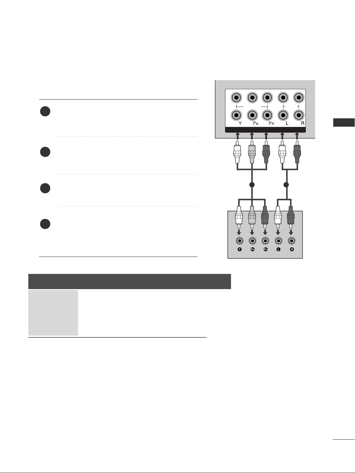
Connecting with a component cable
Connect the video outputs (Y, PB
, PR
)
of the digital TV
top box to the
CCOOMMPPOONN EE NNTT II NN VVIIDD EE OO
jacks on the
TV.
Connect the audio output of the digital set-top box to
the
CCOOMMPPOONN EE NNTT II NN AAUU DDIIOO
jacks on the TV.
Turn on the digital set-top box.
(
Refer to the owner’s manual for the digital set-top box.
)
Select
CCoomm ppoonnee nntt11
input source using the
II NNPP UU TT
button on the remote control.
If connected to
CCOOMMPPOONNEE NNTT II NN 22
, select
CCoomm ppoonnee nntt22
input source.
2
3
4
1
■
To avoid damaging any equipment, never plug in any power cords until you have finished connecting all equipment.
■
This section on EXTERNAL EQUIPMENT SETUP mainly uses diagrams for the 42/50/60PG6
***
models.
■
Image shown may differ from your TV.
Signal
480i/576i
480p/576p
720p/1080i
10 8 0 p
Component
Yes
Yes
Yes
Yes
(50Hz, 60Hz only)
HDMI1/DVI, HDMI2, HDMI3(except
32/37LG6
***
, 32/42LG8
***
)
No
Yes
Yes
Yes
(24Hz, 30Hz, 50Hz, 60Hz)
Page 22
20
EXTERNAL EQUIPMENT SETUP
HDMI IN HDMI DVI IN
HDMI/DVI IN
1
HDMI IN HDMI DVI IN
HDMI IN HDMI IN HDMI/DVI IN HDMI/DVI IN
1 2
L/ MONO
R
AUDIO
AV
VIDEO
IN 1
OUT
VARIABLE AUDIO OUT
1
EXTERNAL EQUIPMENT SETUP
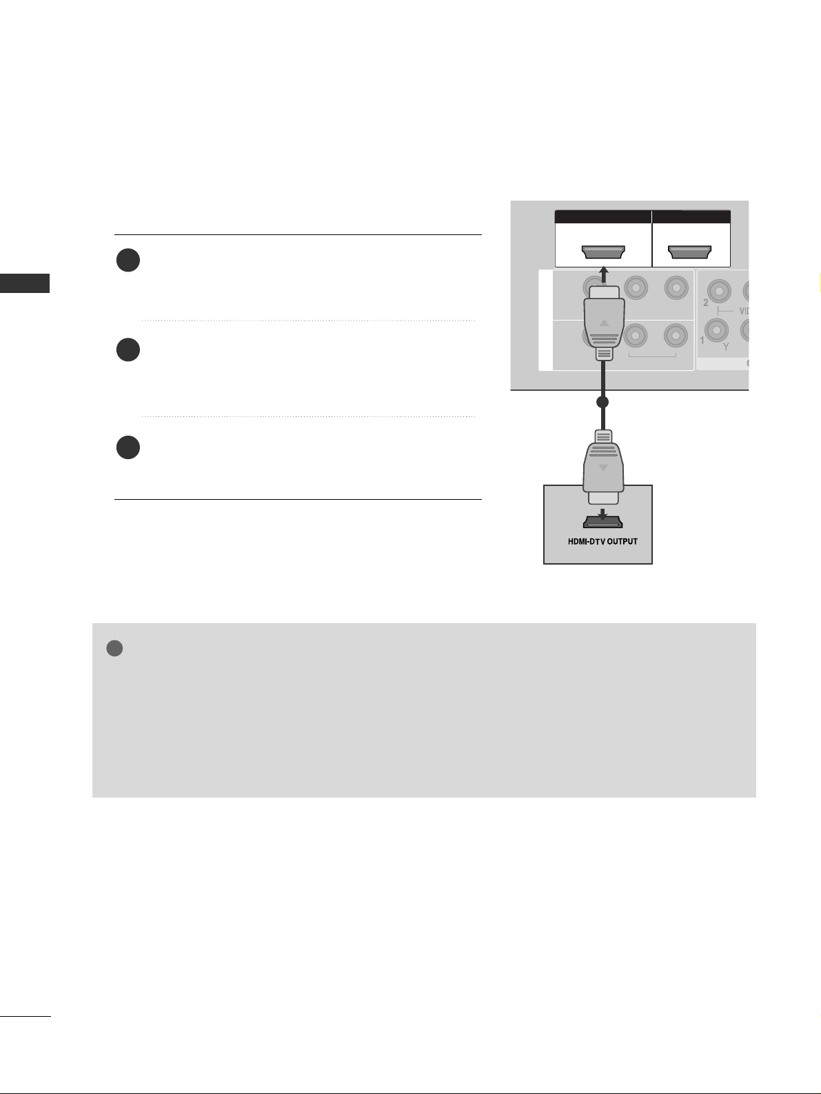
Connecting a set-top box with an HDMI cable
Connect the HDMI output of the digital set-top box to
the
HHDDMMII//DD VVII IINN 11,, HHDDMMII IINN 22 orHHDDMMII II NN
33
(except 32/37LG6
***
, 32/42LG8
***
) jack on the TV.
Select
HHDDMMII11// DDVVII,, HHDDMM II 22
or
HHDDMMII33
(except
32/37LG6
***
, 32/42LG8
***
) input source using the
II NNPP UU TT
button on the remote control.
Turn on the digital set-top box.
(
Refer to the owner’s manual for the digital set-top box.
)
2
3
1
GG
TV can receive the video and audio signal simultaneously with using a HDMI cable.
GG
If the digital set-top box supports Auto HDMI function, the output resolution of the source device will
be automatically TV to 1280x720p.
GG
If the digital set-top box player does not support Auto HDMI, you need to TV the output resolution
appropriately.
To get the best picture quality, adjust the output resolution of the source device to 1280x720p.
(42/47LG6
***
, 42/47/52LG7
***
, 50PG3
***
, 50/60PG7
***
, 32/42LG80F
*
: 1920x1080i/1080p)
NOTE
!
Page 23
21
EXTERNAL EQUIPMENT SETUP
HDMI IN HDMI DVI IN
HDMI/DVI IN HDMI/DVI IN
1
AUDIO
(RGB/DVI)
RGB
(PC)
RGB IN
RS-232C IN
(CONTROL)
L/ MONO
R
AUDIO
AV
VIDEO
IN 1
OUT
VARIABLE AUDIO OUT
1
2
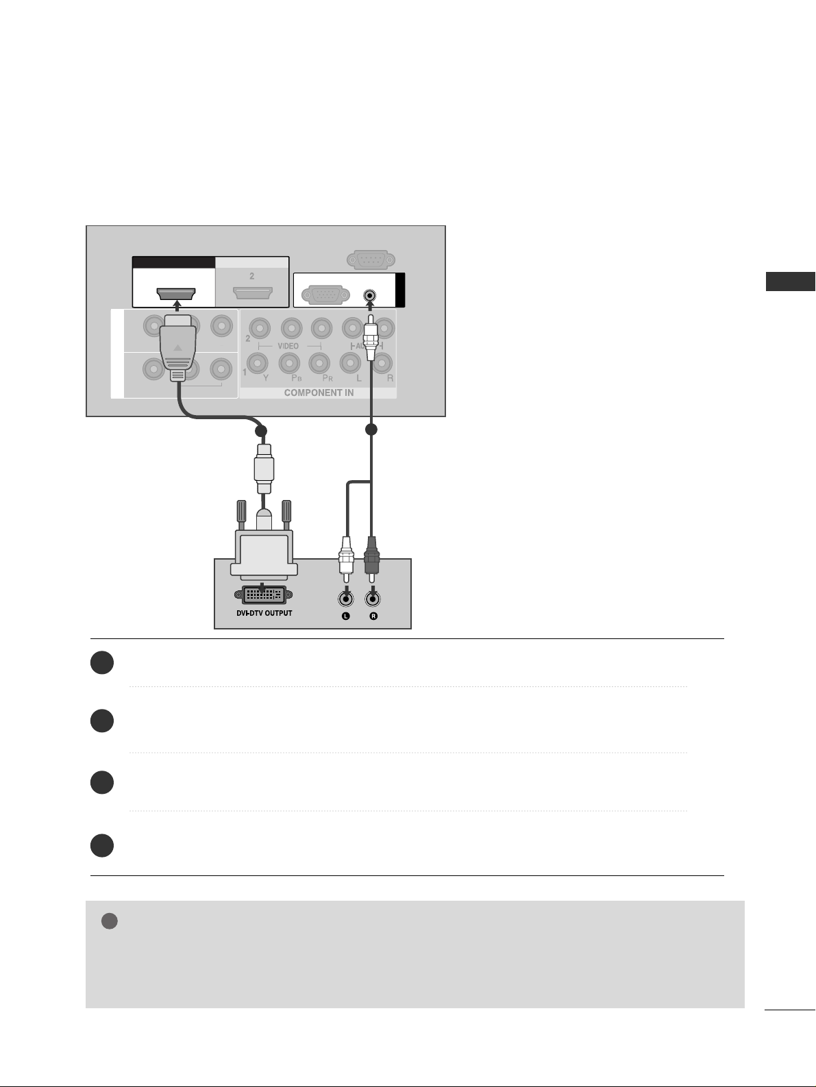
Connect the DVI output of the digital set-top box to the
HHDDMMII//DD VVII IINN 11
jack on the TV.
Connect the audio output of the digital set-top box to the
AA UUDDIIOO(( RR GGBB//DDVVII))
jack on the TV.
Turn on the digital set-top box. (Refer to the owner’s manual for the digital set-top box.
)
Select
HHDDMMII11// DDVVII
input source using the
II NNPP UU TT
button on the remote control.
2
3
4
1
Connecting with a HDMI to DVI cable
GG
HDMI2, HDMI3(except 32/37LG6
***
, 32/42LG8
***
) source does not support DVI source.
GG
If the set-top box has a DVI output and no HDMI output, a separated audio connection is necessary.
GG
If the set-top box does not support Auto DVI, you need to set the output resolution appropriately.
NOTE
!
Page 24
22
EXTERNAL EQUIPMENT SETUP
1
2
COMPONENT IN
VIDEO
AUDIO
1 2
DVD SETUP
EXTERNAL EQUIPMENT SETUP
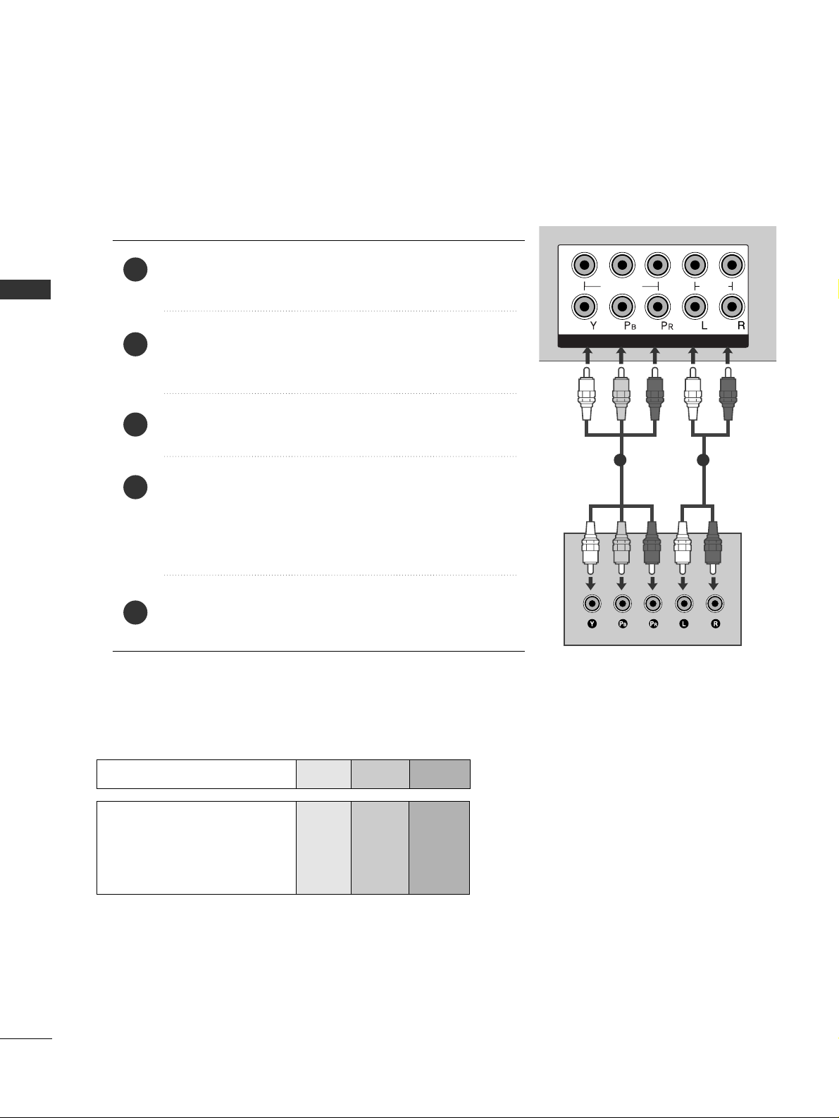
Connecting with a component cable
Component Input ports
To achieve better picture quality, connect a DVD player to the component input ports as shown below.
Component ports on the TV
YPBP
R
Video output ports
on DVD player
Y
Y
Y
Y
P
B
B-Y
Cb
Pb
P
R
R-Y
Cr
Pr
Connect the video outputs (Y, PB
, PR
)
of the DVD to the
CCOOMMPPOONN EE NNTT II NN VVIIDD EE OO
jacks on the TV.
Connect the audio outputs of the DVD to the
CCOOMMPPOONN EE NNTT II NN AAUU DDIIOO
jacks on the TV.
Turn on the DVD player, insert a DVD.
Select
CCoomm ppoonnee nntt11
input source using the
II NNPP UU TT
button on
the remote control.
If connected to
CCOOMMPPOONNEENNTT IINN 22
, select
CCoo mmppoonneenntt 22
input source.
Refer to the DVD player's manual for operating instructions.
2
3
4
5
1
Page 25
23
EXTERNAL EQUIPMENT SETUP
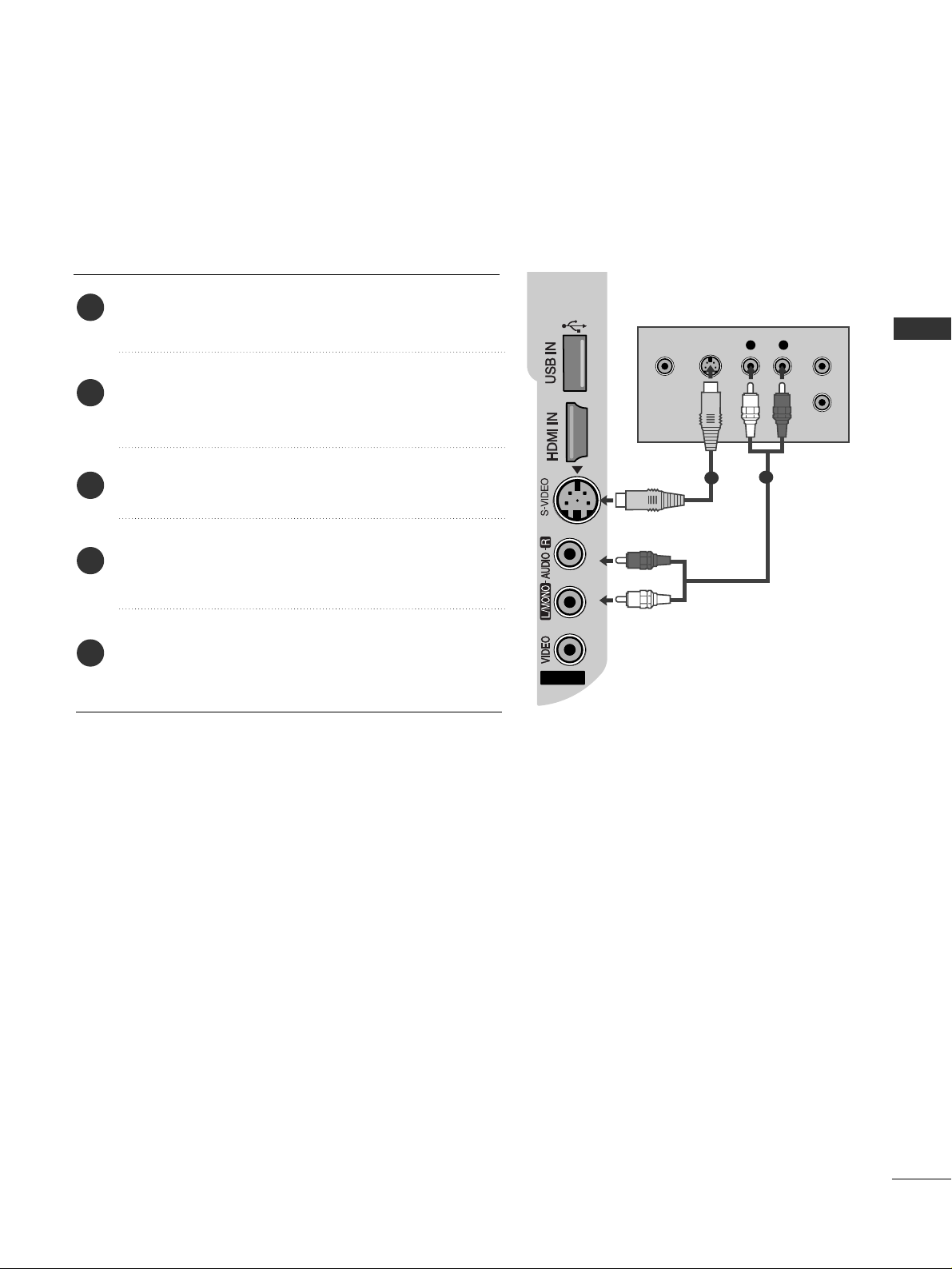
Connecting with a S-Video cable
Connect the S-VIDEO output of the DVD to the
SS --VVII DDEEOO
input on the TV.
Connect the audio outputs of the DVD to the
AA UU DDIIOO
input jacks on the TV.
Turn on the DVD player, insert a DVD.
Select
AAVV 22
input source using the
II NNPP UU TT
button on
the remote control.
Refer to the DVD player's manual for operating
instructions.
2
3
4
5
1
AV IN 2
3
L R
S-VIDEOVIDEO
OUTPUT
SWITCH
ANT IN
ANT OUT
1
2
Page 26
24
EXTERNAL EQUIPMENT SETUP
EXTERNAL EQUIPMENT SETUP
HDMI IN HDMI DVI IN
HDMI IN HDMI IN HDMI/DVI IN HDMI/DVI IN
1 2
HDMI IN HDMI DVI IN
AV IN 2
L/ MONO
R
AUDIO
AV
VIDEO
IN 1
OUT
VARIABLE AUDIO OUT
1
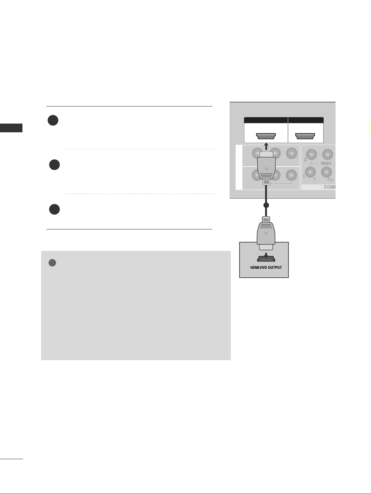
Connecting with a HDMI cable
Connect the HDMI output of the DVD to the
HHDDMMII//DD VVII IINN 11,, HHDD MMII IINN 22 orHHDDMMII II NN
33
(except 32/37LG6
***
, 32/42LG8
***
) jack on the TV.
Select
HHDDMMII11// DDVVII,, HHDDMM II 22 orHHDDMMII33
(except
32/37LG6
***
, 32/42LG8
***
) input source using the
II NNPP UU TT
button on the remote control.
Refer to the DVD player's manual for operating
instructions.
1
GG
The TV can receive video and audio signals simultaneously when
using a HDMI cable.
GG
If the DVD player supports Auto HDMI function, the output resolution of the source device will be automatically TV to 1280x720p.
GG
If the DVD player does not support Auto HDMI, you must TV the
output resolution appropriately.
To get the best picture quality, adjust the output resolution of the
source device to 1280x720p.
(42/47LG6
***
, 42/47/52LG7
***
, 50PG3
***
, 50/60PG7
***
,
32/42LG80F* : 1920x1080i/1080p)
NOTE
!
2
3
Page 27

25
EXTERNAL EQUIPMENT SETUP
HDMI IN HDMI DVI IN
ANTENNA
IN
OUTPUT
SWITCH
ANT IN
R
S-VIDEO VIDEO
ANT OUT
L
Wall Jack
Antenna
1
2
VCR SETUP
Connecting with a RF cable
■
To avoid picture noise (interference), allow adequate distance between the VCR and TV.
■
Typically a frozen still picture from a VCR. If 4:3 picture format is used for an extended period the fixed
images on the sides of the screen may remain visible.
Connect the
AA NNTT OOUU TT
socket of the VCR to the
AA NNTTEENNNNAA II NN
socket on the TV.
Connect the antenna cable to the
AA NNTT IINN
socket of the VCR.
Press the
PP LL AA YY
button on the VCR and match the appropriate programme between the TV and VCR for
viewing.
1
2
2
3
1
Page 28
26
EXTERNAL EQUIPMENT SETUP
Connecting with a RCA cable
L/ MONO
R
AUDIO
VIDEO
VIDEO
L
R
AUDIO
HDMI IN HDMI DVI IN
HDMI IN HDMI DVI IN
L/ MONO
R
AUDIO
AV
VIDEO
IN 1
OUT
VARIABLE AUDIO OUT
L
R
S-VIDEO
VIDEO
OUTPUT
SWITCH
ANT IN
ANT OUT
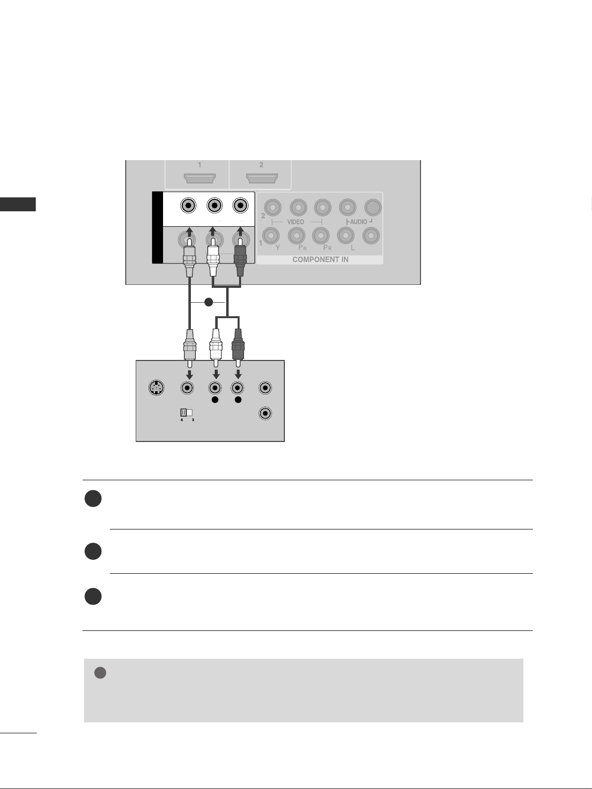
Connect the
AA UU DDIIOO/VVII DDEEOO
jacks between TV and VCR. Match the jack colours (Video = yellow,
Audio Left = white, and Audio Right = red)
Insert a video tape into the VCR and press PLAY on the VCR. (Refer to the VCR owner’s manual.
)
Select
AAVV 11
input source using the
II NNPP UU TT
button on the remote control.
If connected to
AA VV II NN 22
, select
AAVV 22
input source.
1
2
3
GG
If you have a mono VCR, connect the audio cable from the VCR to the
AA UU DDIIOO LL // MMOONN OO
jack
of the TV.
NOTE
!
1
EXTERNAL EQUIPMENT SETUP
Page 29
27
EXTERNAL EQUIPMENT SETUP
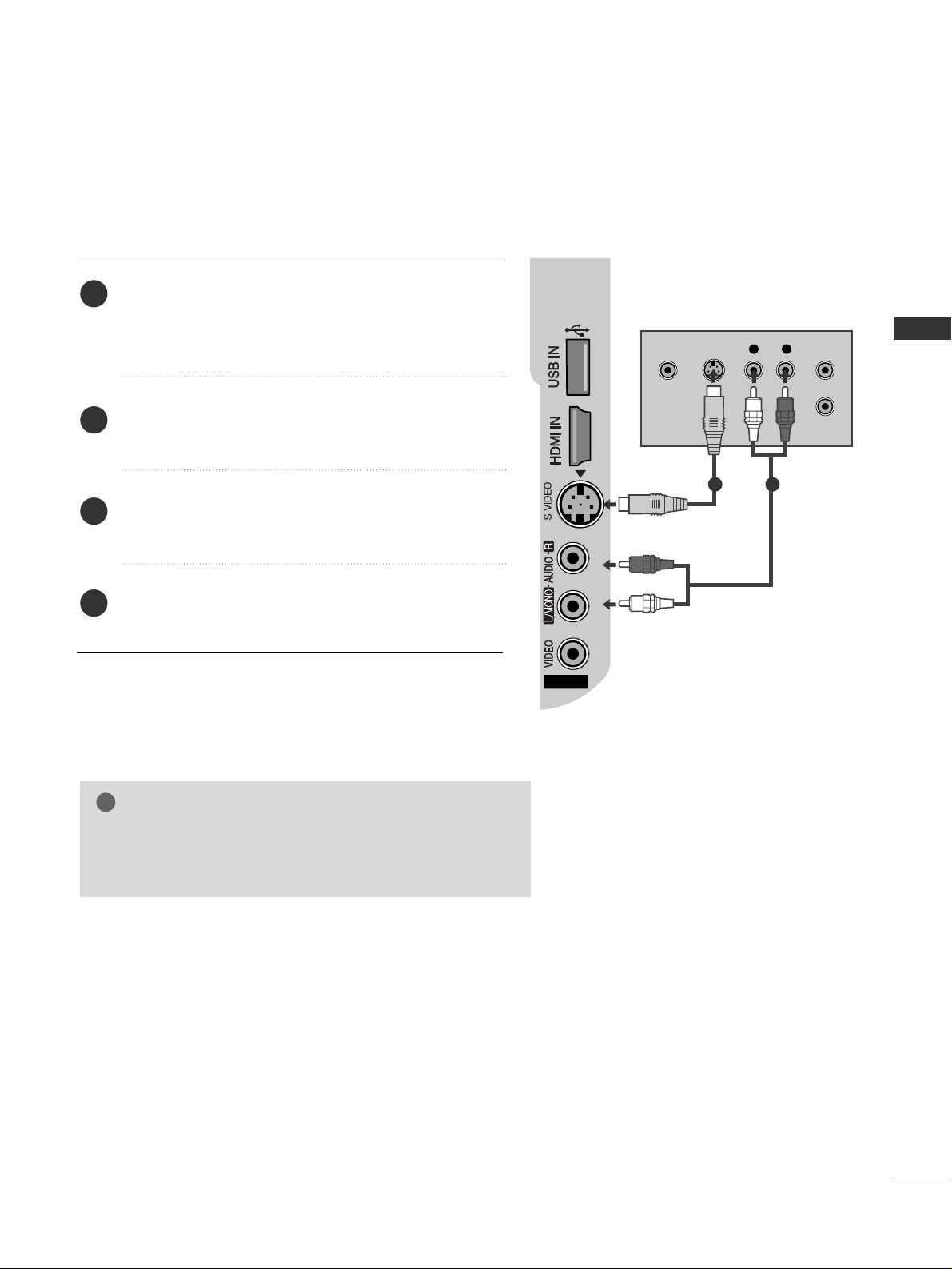
GG
If both S-VIDEO and VIDEO sockets have been connected
to the S-VHS VCR simultaneously, only the S-VIDEO can
be received.
NOTE
!
AV IN 2
3
L R
S-VIDEOVIDEO
OUTPUT
SWITCH
ANT IN
ANT OUT
Connecting with a S-Video cable
Connect the S-VIDEO output of the VCR to the
SS --VVII DDEEOO
input on the TV. The picture quality is
improved; compared to normal composite (RCA cable)
input.
Connect the audio outputs of the VCR to the
AA UU DDIIOO
input jacks on the TV.
Insert a video tape into the VCR and press PLAY on
the VCR. (Refer to the VCR owner’s manual.)
Select
AAVV 22
input source using the
II NNPP UU TT
button on
the remote control.
2
3
4
1
1 2
Page 30

28
EXTERNAL EQUIPMENT SETUP
AV IN 2
3
L R
VIDEO
Camcorder
Video Game Set
1
EXTERNAL EQUIPMENT SETUP
OTHER A/V SOURCE SETUP
Connect the
AA UU DDIIOO/VVII DDEEOO
jacks between TV and external equipment. Match the jack colours
.
(
Video = yellow, Audio Left = white, and Audio Right = red
)
Select
AAVV 22
input source using the
II NNPP UU TT
button on the remote control.
If connected to
AA VV II NN 11
, select
AAVV 11
input source.
Operate the corresponding external equipment.
Refer to external equipment operating guide.
1
2
3
Page 31

29
EXTERNAL EQUIPMENT SETUP
EXTERNAL STEREO SETUP
HDMI IN HDMI DVI IN
HDMI IN HDMI DVI IN
L/ MONO
R
AUDIO
AV
VIDEO
OUT
VARIABLE AUDIO OUT
GG
When connecting with external audio equipments, such as
amplifiers or speakers, please turn the TV speakers off.
(
GG
pp..8866
)
GG
Select
VVaarriiaabbllee OOuutt
in
AAuuddiioo
menu to connect the
VVAA RR IIAABBLLEE AAUU DDII OO OOUU TT
jacks.(
GG
pp..8866
)
NOTE
!
Use to connected either an external amplifier, or add a sub-woofer
to your surround sound system.
Connect the input jack of the stereo amplifier to the
VVAA RR IIAABBLLEE AAUU DDII OO OOUU TT
jacks on the TV.
Set up your speakers through your analog stereo
amplifier, according to the instructions provided with
the amplifier.
2
1
11
Page 32

30
EXTERNAL EQUIPMENT SETUP
EXTERNAL EQUIPMENT SETUP
AV OUTPUT SETUP
The TV has a special signal output capability which allows you
to hook up the second TV or monitor.
HDMI IN HDMI DVI IN
L/ MONO
R
AUDIO
AV
VIDEO
OUT
VARIABLE AUDIO OUT
L R
S-VIDEO
VIDEO
Connect the second TV or monitor to the TV’s
AAVV OOUUTT
jacks.
See the Operating Manual of the second TV or monitor
for further details regarding that device’s input settings.
GG
Component, RGB, HDMI input sources cannot be used for
AV out.
GG
We recommend to use the AV OUT jacks for VCR recording.
NOTE
!
2
1
1
Page 33

31
EXTERNAL EQUIPMENT SETUP
HDMI IN HDMI DVI IN
AUDIO
(RGB/DVI)
RGB
(PC)
RGB IN
RGB OUTPUT
AUDIO
HDMI IN HDMI DVI IN
HDMI/DVI IN
1
L/ MONO
R
AUDIO
AV
VIDEO
IN 1
OUT
VARIABLE AUDIO OUT
1
2
PC SETUP
This TV provides Plug and Play capability, meaning that the PC adjusts automatically to the TV's settings.
Connecting with a D-sub 15 pin cable
Connect the RGB output of the PC to the
RRGG BB((PP CC
))
jack on the TV.
Connect the PC audio output to the
AA UUDDIIOO(( RR GGBB//DDVVII))
jack on the TV.
Turn on the PC and the TV.
Select
RRGGBB PPCC
input source using the
II NNPP UU TT
button on the remote control.
2
3
4
1
Page 34

32
EXTERNAL EQUIPMENT SETUP
EXTERNAL EQUIPMENT SETUP
NOTE
!
GG
To enjoy vivid picture and sound, connect the PC
to the TV.
GG
Avoid keeping a fixed image on the TV ’s screen
for prolonged periods of time.The fixed image
may become permanently imprinted on the
screen;use a screen saver when possible.
GG
Connect the PC to the RGB (PC) port of the TV;
change the resolution output of PC accordingly.
GG
There may be interference relating to resolution,
vertical pattern, contrast or brightness in PC
mode. Change the PC mode to another resolution or change the refresh rate to another rate
or adjust the brightness and contrast on the
menu until the picture is clear. If the refresh rate
of the PC graphic card can not be changed,
change the PC graphic card or consult the manufacturer of the PC graphic card.
GG
The synchronization input waveform for
Horizontal and Vertical frequencies are separate.
GG
If the resolution of PC is over SXGA, there will
be no picture on the TV.(only HD Models)
GG
Connect the audio cable from the PC to the
Audio input on the TV.(Audio cables are not
included with the TV).
GG
If you use too long an RGB-PC cable, there may
be interference on the screen. We recommend
using under 5m of the cable. This provides the
best picture quality.
Page 35

33
EXTERNAL EQUIPMENT SETUP
Resolution
720x480
720x576
1280x720
1920x1080i
1920x1080p
HDMI-DTV mode
Horizontal Vertical
Frequency(kHz) Frequency(Hz)
31.47 59.94
31.50 60.00
31.25 50.00
44.96 59.94
45.00 60.00
37.50 50.00
33.72 59.94
33.75 60.00
28.125 50.00
67. 432 59. 94
67. 5 60
56.250 50
27 24
33.75 30
Resolution
640x350
720x400
640x480
800x600
1024x768
1280x768
1360x768
1366x768
1280x1024
1920x1080
RGB-PC mode
Horizontal Vertical
Frequency(kHz) Frequency(Hz)
31.468 70.09
31.469 70.09
31.469 59.94
37.879 60.317
48.363 60.004
47.776 59.87
47.720 59.799
47. 7 60
63.668 59.895
66.587 59.934
Only 50/60PG6
***
Only 50/60PG7
***
, 50PG3
***
Plasma TV models
Resolution
720x480
720x576
1280x720
1920x1080i
1920x1080p
HDMI-DTV mode
Horizontal Vertical
Frequency(kHz) Frequency(Hz)
31.47 59.94
31.50 60.00
31.25 50.00
44.96 59.94
45.00 60.00
37.50 50.00
33.72 59.94
33.75 60.00
28.125 50.00
67. 432 59. 94
67. 5 60
56.250 50
27 24
33.75 30
Resolution
640x350
720x400
640x480
800x600
1024x768
1280x768
1360x768
1366x768
1280x1024
1920x1080
RGB-PC mode
Horizontal Vertical
Frequency(kHz) Frequency(Hz)
31.468 70.09
31.469 70.09
31.469 59.94
37.879 60.317
48.363 60.004
47.776 59.87
47.720 59.799
47. 7 60
63.668 59.895
66.587 59.934
Only 42/47LG6
***
, 42/47/52LG7
***
, 32/42LG80F
*
LCD TV models
Supported Display Resolution
Page 36

34
EXTERNAL EQUIPMENT SETUP
EXTERNAL EQUIPMENT SETUP
Press the
MMEENN UU
button and then use
//
button to
select the
PPiiccttuurree
menu.
Press the button and then use
//
button to select
SSccrreeeenn
.
Press the button and then use
//
button to select
AAuuttoo CCoo nnffii gg ..
.
Press the button to start
AAuuttoo CCoo nnffii gg
..
• When Auto config. has finished, OK will be shown on
screen.
• If the position of the image is still not correct, try Auto
adjustment again.
• If picture needs to be adjusted again after Auto adjustment
in RGB (PC), you can adjust the
MMaannuuaall CCoo nn ffii gg ..
.
Press the
MMEE NNUU
button to return to normal TV viewing.
Press the
RREETTUURRNN
button to move to the previous menu screen.
Automatically adjusts picture position and minimizes image
instability. After adjustment, if the image is still not correct, your
TV is functioning properly but needs further adjustment.
AAuuttoo ccoo nnffiigguurr ee
This function is for automatic adjustment of the screen position,
clock, and phase. The displayed image will be unstable for a few
seconds while the auto configuration is in progress.
1
2
3
4
5
1
3 4
Screen Setup for PC mode
Auto Configure (RGB [PC] mode only)
Picture Mode
Colour Temperature
Advanced
Aspect Ratio
Picture Reset
Screen
Picture
Screen
Auto config.
Manual Config.
XGA Mode
Reset
To Set
Auto Config. G
DE F G
OK RETURN
2
Picture
Picture Mode
Colour Temperature
Advanced
Aspect Ratio
Picture Reset
Screen
To Set
Screen G
DE F G
OK RETURN
DE F G
OK RETURN
MUTE
RETURN
AV M OD E
FAV
TV
INPUT
STB
POWER
Q. MENU
MENU
OK
DVD
P
Page 37

35
EXTERNAL EQUIPMENT SETUP
MUTE
RETURN
AV MODE
FAV
TV
INPUT
STB
POWER
Q. MENU
MENU
OK
DVD
P
If the picture is not clear after auto adjustment and especially if
characters are still trembling, adjust the picture phase manually.
It’s not available to use Phase, Clock function in
COMPONENT (480i/480p/576i/576p/720p/1080i/1080p),
HDMI (480p/576p/720p/1080i/1080p).
CC lloocckk
This function is to minimize any vertical bars or stripes
visible on the screen background the horizontal screen
size will also change.
PP hhaa ssee
This function allows you to remove any horizontal noise
and clear or sharpen the image of characters.
Press the
MMEENN UU
button and then use
//
button to
select the
PPiiccttuurree
menu.
Press the button and then use
//
button to select
SSccrreeeenn
.
Press the button and then use
//
button to select
MMaannuuaall CCoo nn ffii gg ..
.
Press the button and then use
//
button to select
PPhhaass ee, CCll oo cc kk, HH--PPooss iittii oonn
or
VV--PP oossii ttiioonn
.
Press the
//
button to make appropriate adjustments.
Press the
MMEE NNUU
button to return to normal TV viewing.
Press the
RREETTUURRNN
button to move to the previous menu
screen.
1
2
3
4
5
6
Manual Config. (RGB [PC] mode only)
- Adjustment for screen Phase, Clock, Position
3 4 5
1
Picture Mode
Colour Temperature
Advanced
Aspect Ratio
Picture Reset
Screen
Picture
2
Picture
Picture Mode
Colour Temperature
Advanced
Aspect Ratio
Picture Reset
Screen
To Set
Screen G
DE F G
OK RETURN
DE F G
OK RETURN
Screen
Auto config.
Manual Config.
XGA Mode
Reset
Manual Config. G
DE F G
OK RETURN
Phase 51
Clock 50
H-Position 50
V-Position 50
Page 38

36
EXTERNAL EQUIPMENT SETUP
To view a normal picture, match the resolution of RGB mode
and selection of XGA mode.
This function works in the following mode: RGB[PC] mode.
Press the
MMEENN UU
button and then use
//
button to
select the
PP iicc tt uu rree
menu.
Press the button and then use
//
button to select
SS ccrreeee nn
.
Press the button and then use
//
button to select
XXGG AA MMoodd ee
.
Press the button and then use
//
button to select
the desired XGA resolution.
Press the
MMEE NNUU
button to return to normal TV viewing.
Press the
RREETTUURRNN
button to move to the previous menu
screen.
Selecting XGA mode (except 42PG6
***
)
1
2
3
4
5
EXTERNAL EQUIPMENT SETUP
MUTE
RETURN
AV MODE
FAV
TV
INPUT
STB
POWER
Q. MENU
MENU
OK
DVD
P
1
3 4
Picture Mode
Colour Temperature
Advanced
Aspect Ratio
Picture Reset
Screen
Picture
Screen
Auto config.
Manual Config.
XGA Mode
Reset
XGA Mode G
DE F G
OK RETURN
2
Picture
Picture Mode
Colour Temperature
Advanced
Aspect Ratio
Picture Reset
Screen
To Set
Screen G
DE F G
OK RETURN
DE F G
OK RETURN
1024x768
1280x768
1360x768
1366x768
* except 50/60PG6
***
Page 39

37
EXTERNAL EQUIPMENT SETUP
This function operates in current mode.
To initialize the adjusted value
Press the MENU button and then use
//
button to
select the
PP iicc tt uu rree
menu.
Press the button and then use
//
button to select
SS ccrreeee nn
.
Press the button and then use
//
button to select
RReess eett
.
Press the button.
Press the
MMEE NNUU
button to return to normal TV viewing.
Press the
RREETTUURRNN
button to move to the previous menu screen.
1
2
3
4
5
Initializing (Reset to original factory settings)
MUTE
RETURN
AV MODE
FAV
TV
INPUT
STB
POWER
Q. MENU
MENU
OK
DVD
P
1
3 4
Picture Mode
Colour Temperature
Advanced
Aspect Ratio
Picture Reset
Screen
Picture
Screen
Auto config.
Manual Config.
XGA Mode
Reset
Reset G
DE F G
OK RETURN
2
Picture
Picture Mode
Colour Temperature
Advanced
Aspect Ratio
Picture Reset
Screen
To Set
Screen G
DE F G
OK RETURN
DE F G
OK RETURN
To Set
Page 40

38
WATCHING TV / PROGRAMME CONTROL
WATCHING TV / PROGRAMME CONTROL
REMOTE CONTROL KEY FUNCTIONS
When using the remote control, aim it at the remote control sensor on the TV.
MUTE
RETURN
AV MODE
FAV
TV
INPUT
STB
POWER
Q. MENU
MENU
OK
P
123
456
7809
LIST
Q.VIEW
DVD
TIME
SIZE
UPDATE
REVEAL
INDEX
HOLD TEXT
PIP
MODE
POWER
INPUT
Selects the remote operating modes.
Switches the TV on from standby or off to standby.
External input mode rotate in regular sequence.
Switches the TV on from standby.
Q. MENU
MENU
Select the desired quick menu source.
Selects a menu.
Clears all on-screen displays and returns to TV viewing
from any menu.
See a list of AV devices connected to TV.
When you toggle this button, the Simplink menu
appears at the screen.
RETURN
AV MODE
Allows the user to move return one step in an interactive application or other user interaction function.
Enter to the mode.
It helps you select and set images and sounds when
connecting AV devices.
Coloured
buttons
These buttons are used for teletext (on
TT EELL EETTEEXXTT
models only) ,
PPrrooggrraammmmee eedd iitt
.
TELETEXT
BUTTONS
PIP
These buttons are used for teletext.
For further details, see the ‘Teletext’ section.
Switches the sub picture PIP, DW mode.
1
1
Page 41

39
WATCHING TV / PROGRAMME CONTROL
MUTE
RETURN
AV MODE
FAV
TV
INPUT
STB
POWER
Q. MENU
MENU
OK
P
123
456
7809
LIST
Q.VIEW
DVD
TIME
SIZE
UPDATE
REVEAL
INDEX
HOLD TEXT
PIP
VOLUME UP
/DOWN
FAV
MUTE
Programme
UP/DOWN
0~9 number
button
LIST
Q.VIEW
Adjusts the volume.
Displays the selected favourite programme.
Switches the sound on or off.
Selects a programme.
Selects a programme.
Selects numbered items in a menu.
Displays the programme list.
Returns to the previously viewed programme.
Installing Batteries
■
Open the battery compartment cover on the back and install the
batteries matching correct polarity (+with +,-with -).
■
Install two 1.5V AAA batteries. Do not mix old or used batteries
with new ones.
■
Close cover.
VCR/DVD
control buttons
Controls some video cassette recorders or DVD players.
Control connected AV devices by pressing the
// //
//
, OK buttons and buttons for
G,A
,
ll ll
,
FF
andGG.
(The
Ô
button does not provide such functions.)
THUMBSTICK
(Up/Down/Left
Right)
OK
Allows you to navigate the on-screen menus and adjust
the system settings to your preference.
Accepts your selection or displays the current mode.
Page 42

40
WATCHING TV / PROGRAMME CONTROL
WATCHING TV / PROGRAMME CONTROL
Press the
++ //--
button to adjust the volume.
If you wish to switch the sound off, press the
MMUU TT EE
button.
You can cancel the Mute function by pressing the
MMUU TT EE
or
++ //--
button.
PROGRAMME SELECTION
TURNING ON THE TV
When your TV is turned on, you will be able to use its features.
Firstly, connect the power cord correctly.
At this stage, the TV switches to standby mode.
■
In standby mode to turn TV on, press the ,
II NNPP UU TT,PP
DD
//
EE
( or
PP
//
) button on the TV or press the
PP OOWWEE RR, TT VV, II NNPP UU TT, PP
//
,
NNUUMMBBEERR((00~99 ))
buttons on the remote control and the TV will
switch on.
1
VOLUME ADJUSTMENT
Press the
PP
//
or
NNUUMMBBEERR
buttons to select a programme number.
2
3
1
1
Installation Guide
Note:
a. It will automatically disappear after approx. 40 seconds unless a button is pressed.
b. “In-Store” mode is only for shop display and not for general customer use.
c. "Home” mode is the optimal setting for home environments, and is the TV's default mode.
d. "In-Store" mode is the optimal setting for store environments. If a user modifies image quality data,
“In-Store” mode initializes the product to the image quality set by us after a certain period of time.
e. The mode (Home, In-Store) can be changed by executing Factory Reset in the Option menu.
If the OSD (On Screen Display) is displayed on the screen after turning on the TV, you can adjust the
LL aanngguu aaggee, LL ooccaa tt iioonn, AA uu tt oo TTuunnii nn gg
.
Page 43

41
WATCHING TV / PROGRAMME CONTROL
QUICK MENU
Your TV's OSD (On Screen Display) may differ slightly from that shown in this
manual.
Q.Menu (Quick Menu) is a menu of features which users might use frequently.
•
AA sspp eecctt RRaattiioo
:
Selects your desired picture format.
For Zoom Setting, select 14:9, Zoom1 and Zoom2 in Ratio Menu. After completing
Zoom Setting, the display goes back to Q.Menu.
•
PP oowwee rr SSaa vvii nn gg
(only Plasma TV Models)
: Adjusts screen brightness to reduce the power
consumption of the set.
•
BBaacckklliigghhtt
(only LCD TV Models):Adjusts screen brightness. It returns to the default
settings brightness by changing mode source.
•
PP ii cc ttuu rree MMoodd ee
:
Selects your desired Picture Mode.
•
SSoouunn dd MMoodd ee
: It is a feature to automatically set the sound combination which it deems the
best for the images being watched.
Selects your desired Sound Mode.
•
MMuu lltt ii AAuuddii oo ::
Selects the sound output.
•
PPrrooggrraammmmee EEddii tt ::
Adjusts the stored programmes by delete, copy, move or skip.
•
SSll eeeepp TTiimmee rr
:
Selects the sleep timer.
MUTE
RETURN
AV MODE
FAV
TV
INPUT
STB
POWER
Q. MENU
MENU
OK
DVD
P
Press the
QQ.. MM EE NNUU
button and then
//
button to
display each menu.
Press the
//
button to select your desired Source.
Press the
QQ ..MMEE NNUU
button to return to normal TV viewing.
1
2
3
Aspect Ratio
Power Saving
Backlight
Picture Mode
Sound Mode
Multi Audio
Programme Edit
Sleep Timer
FF
4 : 3
GG
Zoom Setting
0
0
Sport
Sport
L + R
To Set
Off
Q. MENU
DDEE
FF GG
RETURN
* Only PLASMA TV models
* Only LCD TV models
Page 44

42
WATCHING TV / PROGRAMME CONTROL
WATCHING TV / PROGRAMME CONTROL
ON SCREEN MENUS SELECTION AND ADJUSTMENT
Press the
MMEENN UU
button and then
//
button to display each menu.
Press the button and then
//
button to select a menu item.
Change the setting of an item in the sub or pull-down menu with
//
button.
You can move to a higher level menu by pressing the
OO KK
button.
Your TV's OSD (On Screen Display) may differ slightly from that shown in this manual.
NOTE
!
a. The OSD (On Screen Display) function enables you to adjust the screen status conveniently since it
provides graphical presentation.
b. In this manual, the OSD (On Screen Display) may be different from your TV’s because it is just example
to help the TV operation.
c. In the teletext mode and USB mode, menus are not displayed.
Setup MENU
Picture MENU
Audio MENU
Time MENU
Option MENU
1
2
3
Language
SIMPLINK
Key Lock
ISM Method
Power Saving
Set ID
Power Indicator
Factory Reset
Option
Clock
Off Time
On Time
Sleep Timer
Auto Sleep
Time
Auto Tuning
Manual Tuning
Programme Edit
Favourite Programme
Setup
Sound Mode
Auto Volume
Balance 0
TV Speaker
Audio Out
Sliding Mode
Audio
* Only PLASMA TV models
DE F G
OK RETURN
DE F G
OK RETURN
DE F G
OK RETURN
DE F G
OK RETURN
Picture Mode
Colour Temperature
Advanced
Aspect Ratio
Picture Reset
Screen
TruMotion Demo
Picture
DE F G
OK RETURN
Music List
Photo List
Movie List
DivX Reg. Code
USB
DE F G
OK RETURN
USB MENU
* Only LCD TV models
* Only 42/47/52LG7
***
* Only 42LG8
***
Page 45

43
WATCHING TV / PROGRAMME CONTROL
MUTE
RETURN
AV MODE
FAV
TV
INPUT
STB
POWER
Q. MENU
MENU
OK
DVD
P
Press the
MMEENNUU
button and then
//
button to select the
SSeettuupp
menu.
Press the button and then
//
button to select
AAuuttoo
TTuunniinngg
.
Press the button and then
//
button to select
SSyysstteemm
.
Press the
//
button to select a TV system menu;
BG: PAL B/G, SECAM B/G (Europe / East Europe / Asia /
NewZealand / M.East / Africa / Australia)
I : PAL I/II (U.K. / Ireland / Hong Kong / South Africa)
DK: PAL D/K, SECAM D/K (East Europe / China / Africa / CIS)
M : (USA / Korea / Philippines)
Press the
//
button to select
SSttoorraaggee FFrroomm
.
Press the
//
button or NUMBER buttons to select the ini-
tial programme number. If you use NUMBER buttons, any
number under 10 is entered with a numeric ‘0’ in front of it,
i.e.‘
0055
’ for 5.
Press the
//
button to select
SSeeaarrcchh
.
Press the button to begin auto tuning.
All receivable stations are stored.
To stop auto tuning, press the
RREETTUURRNN
button.
When auto tuning is complete, the Programme edit menu
appears on the screen. See the Programme edit section to edit
the stored programme.
Press the
MMEE NNUU
button to return to normal TV viewing.
Press the
RREETTUURRNN
button to move to the previous menu screen.
1
2
3
4
5
6
7
8
9
Up to 100 TV stations can be stored by programme numbers (0 to 99).
Once you have preset the stations, you will be able to use the P
//
or NUMBER buttons to scan the stations you have programmed.
Stations can be tuned using automatic or manual modes.
All stations which can be received are stored by this method. It is
recommended that you use Auto tuning during installation of this TV.
AUTO PROGRAMME TUNING
1
Auto Tuning
System
Storage From
Search
System G
DE F G
OK RETURN
2
Setup
Auto Tuning
Manual Tuning
Programme Edit
Favourite Programme
To Set
Auto Tuning G
DE F G
OK RETURN
3 4 5 6
7
8
BG
I
DK
M
Auto Tuning
Manual Tuning
Programme Edit
Favourite Programme
Setup
Auto Tuning
C 05 BG
5 35%
RETURN Stop
DE F G
OK RETURN
Page 46

44
WATCHING TV / PROGRAMME CONTROL
WATCHING TV / PROGRAMME CONTROL
MANUAL PROGRAMME TUNING
Press the
MMEE NN UU
button and then
//
button to select the
SS eettuupp
menu.
Press the button and then
//
button to select
MMaannuuaall TTuu nn iinn gg
.
Press the button and then
//
button to select
SSttoorraaggee
.
Press the
//
button or NUMBER buttons to select the
desired programme number (0 to 99). If you use NUMBER
buttons, any number under 10 is entered with a numeric ‘0’ in
front of it, i.e. ‘
00 55
’ for 5.
Press the
//
button to select
SS yy ssttee mm
.
Press the
//
button to select a TV system menu;
BG : PAL B/G, SECAM B/G (Europe / East Europe / Asia /
NewZealand / M.East / Africa / Australia)
I : PAL I/II (U.K. / Ireland / Hong Kong / South Africa)
DK : PAL D/K, SECAM D/K (East Europe / China / Africa / CIS)
M : (USA / Korea / Philippines)
Press the
//
button to select
BBaa nn dd
.
Press the button and then
//
button to select
VV// UUHHFF
or
CCaa bbll ee
.
Press the
//
button to select
CChh aannnnee ll
.
You can select the desired programme number with the
//
button or NUMBER buttons. If possible, select the programme
number directly with the number buttons. Any number under
10 is entered with a numeric ‘0’ in front of it, i.e. ‘
00 55
’ for 5.
Press the
//
button to select
SS eeaarrcchh
.
Press the
//
button to commence searching. If a station is
found the search will stop.
Press the
OO KK
button to store it.
To store another station, repeat steps 33to
11 33
.
Press the
MMEE NNUU
button to return to normal TV viewing.
Press the
RREETTUURRNN
button to move to the previous menu screen.
Manual programme lets you manually tune and arrange the
stations in whatever order you desire.
1
2
3
4
5
6
7
8
9
10
11
12
13
14
15
DE F G
OK MENU
73 4 5 6
8 9
10 11 12
MUTE
RETURN
AV MODE
FAV
TV
INPUT
STB
POWER
Q. MENU
MENU
OK
123
456
7809
LIST
Q.VIEW
DVD
P
1
Manual Tuning
Storage
System
Band
Channel
Fine
Search
Name
Booster
Storage G
DE F G
OK RETURN
2
Setup
Auto Tuning
Manual Tuning
Programme Edit
Favourite Programme
To Set
Manual Tuning G
DE F G
OK RETURN
99
Auto Tuning
Manual Tuning
Programme Edit
Favourite Programme
Setup
DE F G
OK RETURN
Page 47

45
WATCHING TV / PROGRAMME CONTROL
FINE TUNING
Press the
MMEENN UU
button and then
//
button to select
the
SSeettuupp
menu.
Press the button and then
//
button to select
MMaannuuaall TTuu nn iinn gg
.
Press the button and then
//
button to select
FF iinnee
.
Press the button and then
//
button to fine tune for
the best picture and sound.
Press the
OO KK
button to store it.
Press the
MMEE NNUU
button to return to normal TV viewing.
Press the
RREETTUURRNN
button to move to the previous menu screen.
1
2
3
4
5
6
Normally fine tuning is only necessary if reception is poor.
3 4 5
MUTE
RETURN
AV M OD E
FAV
TV
INPUT
STB
POWER
Q. MENU
MENU
OK
DVD
P
1
2
Setup
Auto Tuning
Manual Tuning
Programme Edit
Favourite Programme
To Set
Manual Tuning G
DE F G
OK RETURN
Auto Tuning
Manual Tuning
Programme Edit
Favourite Programme
Setup
DE F G
OK MENU
Manual Tuning
Storage
System
Band
Channel
Fine
Search
Name
Booster
Fine G
DE F G
OK RETURN
F/ G
DE F G
OK RETURN
Page 48

46
WATCHING TV / PROGRAMME CONTROL
WATCHING TV / PROGRAMME CONTROL
ASSIGNING A STATION NAME
You can assign a station name up to five characters to each programme number.
Press the
MMEENN UU
button and then
//
button to select
the
SSeettuupp
menu.
Press the button and then
//
button to select
MMaannuuaall TTuu nn iinn gg
.
Press the button and then
//
button to select
NNaammee
.
Press the button and then
//
button. You can use a
blank, ++, --, the number00to 99and the alphabet AAto ZZ.
Press the
//
button to select the position and make
your choice of the second character, and so on.
Press the
OO KK
button to store it.
Press the
MMEE NNUU
button to return to normal TV viewing.
Press the
RREETTUURRNN
button to move to the previous menu screen.
1
2
3
4
5
6
7
3 4 5 6
MUTE
RETURN
AV M OD E
FAV
TV
INPUT
STB
POWER
Q. MENU
MENU
OK
DVD
P
1
2
Setup
Auto Tuning
Manual Tuning
Programme Edit
Favourite Programme
To Set
Manual Tuning G
DE F G
OK RETURN
Auto Tuning
Manual Tuning
Programme Edit
Favourite Programme
Setup
DE F G
OK MENU
Manual Tuning
Storage
System
Band
Channel
Fine
Search
Name
Booster
Name G
DE F G
OK RETURN
C 05
DE F G
OK RETURN
Page 49

47
WATCHING TV / PROGRAMME CONTROL
In some models,
BB ooooss tt ee rr
is an optional function. Only a set
with
BB ooooss tt ee rr
can perform this function.
If reception is poor, select
BB ooooss tteerr
to On.
When the signal is strong, select “OFF”.
BOOSTER
Press the
MMEENNUU
button and then
//
button to select
the
SS EE TT UUPP
menu.
Press the button and then
//
button to select
MMaannuuaall TTuu nn iinn gg
.
Press the button and then use
//
button to select
BBooooss ttee rr
.
Press the button and then use
//
button to select
OO nnorOOff ff
.
Press the
MMEE NNUU
button to return to normal TV viewing.
Press the
RREETTUURRNN
button to move to the previous menu screen.
1
2
3
4
5
MUTE
RETURN
AV MODE
FAV
TV
INPUT
STB
POWER
Q. MENU
MENU
OK
123
DVD
P
3 4
1
2
Setup
Auto Tuning
Manual Tuning
Programme Edit
Favourite Programme
To Set
Manual Tuning G
DE F G
OK RETURN
Auto Tuning
Manual Tuning
Programme Edit
Favourite Programme
Setup
DE F G
OK MENU
Manual Tuning
Storage
System
Band
Channel
Fine
Search
Name
Booster
Booster G
DE F G
OK RETURN
Off
On
DE F G
OK RETURN
Page 50

48
WATCHING TV / PROGRAMME CONTROL
WATCHING TV / PROGRAMME CONTROL
PROGRAMME EDIT
This function enables you to delete or skip stored programmes.
Also you can move some stations to other programme numbers
or copy a blank station data into the selected programme number.
Press the
MMEENN UU
button and then
//
button to select
the
SSeettuupp
menu.
Press the button and then
//
button to select
PPrrooggrraammmmee EEddii tt
.
Press the button to display the
Programme edit menu.
AA
DDeelleettiinngg aa pprrooggrraammmmee
1.Select a programme to be deleted with the
// // //
button.
2.Press the RED button twice.
The selected programme is deleted, all the following
programmes are shifted up one position.
AA
CCooppyyiinngg aa pprrooggrraammmmee
1.Select a programme to be copied with the
// // //
button.
2.Press the GREEN button.
All the following programmes are shifted down one position.
AA
MMoovviinngg aa pprrooggrraammmmee
1.Select a programme to be moved with the
// // //
button.
2.Press the YELLOW button.
3.Move the programme to the desired programme number with
the
// // //
button.
4.Press the YELLOW button again to release this function.
AA
SSkkiippppiinngg aa pprrooggrraammmmee nnuummbbeerr
1.Select a programme number to be skipped with the
//
// //
button.
2.Press the BLUE button. The skipped programme turns to blue.
3.Press the BLUE button again to release the skipped
programme.
When a programme number is skipped it means that you will
be unable to select it using the
//
button during normal
TV viewing. If you wish to select the skipped programme,
directly enter the programme number with the NUMBER
buttons or select it in the programme edit or table menu.
Press the
MMEE NNUU
button to return to normal TV viewing.
Press the
RREETTUURRNN
button to move to the previous menu screen.
1
2
3
4
3
MUTE
RETURN
AV MODE
FAV
TV
INPUT
STB
POWER
Q. MENU
MENU
OK
123
456
7809
LIST
Q.VIEW
DVD
TIME
SIZE
UPDATE
REVEAL
P
1
2
Setup
Auto Tuning
Manual Tuning
Programme Edit
Favourite Programme
To Set
Programme Edit G
DE F G
OK RETURN
Auto Tuning
Manual Tuning
Programme Edit
Favourite Programme
Setup
DE F G
OK RETURN
Programme Edit
DE F G
OK RETURN
Delete
Move
Copy
Skip
0C03 5S69
1 BLN 03 6 S 17
2 C 12 7 S 22
3 S 66 8 C 09
4 S 67 9 C 11
Page 51

49
WATCHING TV / PROGRAMME CONTROL
MUTE
RETURN
AV MODE
FAV
TV
INPUT
STB
POWER
Q. MENU
MENU
OK
123
456
7809
LIST
Q.VIEW
DVD
P
FAVOURITE PROGRAMME
Press the
MMEENNUU
button and then
//
button to select the
SSeettuupp
menu.
Press the button and then
//
button to select
FFaavvoouurriittee PPrrooggrraammmmee
.
Press the button.
Press the
//
button to select - - - - - - -.
Select a desired programme with the
//
button or
NUMBER buttons. Any number under 10 is entered with a
numeric ‘0’in front of it, i.e.‘
0055
’ for 5.
To store another programme, repeat steps
44
to 55.
You can store up to 8 programmes.
Press the
MMEE NNUU
button to return to normal TV viewing.
Press the
RREETTUURRNN
button to move to the previous menu screen.
This function lets you select your favourite programmes directly.
Repeatedly press the FAV button to select stored favourite
programmes.
1
2
3
4
5
6
7
2 3 4 5
1
Setup
Auto Tuning
Manual Tuning
Programme Edit
Favourite Programme
Favourite Programme G
DE F G
OK RETURN
Auto Tuning
Manual Tuning
Programme Edit
Favourite Programme
Setup
-- -----
-- -----
-- -----
-- -----
-- -----
-- -----
-- -----
-- -----
DE F G
OK RETURN
Page 52

50
WATCHING TV / PROGRAMME CONTROL
WATCHING TV / PROGRAMME CONTROL
MUTE
RETURN
AV MODE
FAV
TV
INPUT
STB
POWER
Q. MENU
MENU
OK
123
456
7809
LIST
Q.VIEW
DVD
TIME
SIZE
UPDATE
REVEAL
INDEX
HOLD TEXT
PIP
P
SELECTING THE PROGRAMME LIST
You can check which programmes are stored in the memory by
displaying the programme list.
AA
DDiissppll aayy iinngg pprroo ggrraamm mmee lliisstt
Press the
LLIISSTT
button to display the Programme
list
menu.
The programme
list
appears on the screen.
One programme
list
contains ten programmes as shown.
AA
SSeell eeccttii nngg aa pp rrooggrraa mmmmee iinn tthhee pp rrooggrraa mmmmee llii sstt
Select a programme with the
// // //
button.
Then press the
OO KK
button. The TV switches to the chosen
programme number.
AA
PPaa ggiinngg tthhrroouu gghh aa pp rrooggrraa mmmmee llii sstt
There are 10 programme table pages in which contain 100 pro
grammes. Pressing the
// // //
button repeatedly turns the
pages.
Press the
LL II SSTT
button to return to normal TV viewing.
NOTE
!
a. You may find some blue programmes. They have been set up
to be skipped by auto programming or in the programme edit
mode.
b. Some programmes with the channel number shown in the
programme list indicate there is no station name assigned.
Programme List
FG DE
OK
0C03 5S69
1 BLN 03 6 S 17
2 C 12 7 S 22
3 S 66 8 C 09
4 S 67 9 C 11
Page 53

51
WATCHING TV / PROGRAMME CONTROL
32
Option
Language SIMPLINK Key Lock ISM Method Power Saving Set ID Power Indicator Factory Reset
SIMPLINK G
DE F G
OK RETURN
Off
On
1
This function operates only with devices with the SIMPLINK logo.
Please check the SIMPLINK logo.
The product might not function properly when using it with other
products with HDMI-CEC function.
This allows you to control and play other AV devices connected
to the display through HDMI cable without additional cables and
settings.
If you do not require the SIMPLINK menu, select “Off ”.
Press the
MMEENN UU
button and then
//
button to select
the
OOpptt iioo nn
menu.
Press the button and then
//
button to select
SS II MMPP LLIINN KK
.
Press the button and then
//
button to select
OO nn
or
OO ffff
.
Press the
MMEE NNUU
button to return to normal TV viewing.
Press the
RREETTUURRNN
button to move to the previous menu screen.
1
2
3
4
MUTE
RETURN
AV MODE
FAV
TV
INPUT
STB
POWER
Q. MENU
MENU
OK
123
456
7809
LIST
Q.VIEW
DVD
TIME
SIZE
UPDATE
REVEAL
INDEX
HOLD TEXT
PIP
P
Language
SIMPLINK
Key Lock
ISM Method
Power Saving
Set ID
Power Indicator
Factory Reset
Option
DE F G
OK RETURN
Page 54

52
WATCHING TV / PROGRAMME CONTROL
TV
DISC
VCR
HDD Recorder
SPEAKER
TV SPEAKER
WATCHING TV / PROGRAMME CONTROL
NOTE
!
GG
Connect the HDMI/DVI IN or HDMI IN terminal of the TV to the rear terminal and Side terminal (HDMI
terminal) of the SIMPLINK device with the HDMI cable.
GG
After connecting the HDMI terminal for the home theatre with SIMPLINK function using the above
method, connect the VARIABLE AUDIO OUT terminal on the back of the TV to the VARIABLE AUDIO IN
terminal on the back of the SIMPLINK device with the VARIABLE AUDIO OUT cable.
GG
When operating an external device with SIMPLINK, press the TV button from the MODE button on the
remote control.
GG
When you switch the Input source using the INPUT button on the remote control, you can stop the
operation of a device controlled by SIMPLINK.
GG
When you select or operate a media device with home theatre function, the speaker automatically
switches to home theatre speaker (HT speaker).
DDiiss cc pp ll aayybb aacc kk
Control connected AV devices by pressing the
// // //
,
OK, G, A,
ll ll
, FFand GGbuttons.
(The
Ô
button does not provide such functions)
DDiirree cctt PP ll aa yy
After connecting AV devices to the TV, you can directly control the devices and play media without additional settings.
SSeell ee cctt AAVV dd ee vv ii ccee
Enables you to select one of the AV devices connected to the TV and operate it.
PP oo ww eerr ooffff aa ll ll ddeevviicc eess
When you switch off the TV, all connected devices are turned off.
SSww ii ttcchh aauuddiioo --oouu tt
Offers an easy way to switch audio-out.
SSyy nncc PP oowweerr OOnn
The television set will change automatically to turn on mode, after the Player with Simplink function start to
reproduce through connection HDMI.
** AA dd ee vv ii ccee,, wwhhiicc hh iiss cc oo nnnneecc ttee dd tt oo tt hhee TTVV tthhrroouugghh aa HH DDMMII ccaa bb ll ee bbuutt ddooeess nnoott ss uu pp ppoorr tt SSII MMPPLL IINNKK ,, dd oo eess nnoott
pprr oovvii ddee tthhii ss ffuunn ccttiioo nn..
SIMPLINK Functions
TT VV vviieeww iinngg ::
Switch to the previous TV programme
regardless of the current mode.
DDIISSCC pp llaayybbaacckk ::
Select and play discs. When
multiple discs are available, the titles of the discs are
conveniently displayed at the bottom of the screen.
VVCCRR ppll aayybbaacckk ::
Control the connected VCR.
HHDDDD RReeccoorrddiinnggss ppllaa yy bbaa cckk ::
Control recordings
stored in HDD.
AA uu ddiioo OOuutt ttoo HH oommee tthh eeaattee rr//AA uu ddiioo OOuutt ttoo TTVV
::
Select Home theater or TV speaker for Audio Out.
Selected Device
When device is not
connected (displayed
in gray)
When a device is
connected (displayed
in bright colour)
1
2
3
4
5
1
2
3
4
5
SIMPLINK Menu
Press the
// // //
button and then OK button to select the desired SIMPLINK source.
DDEE
OK
Page 55

53
WATCHING TV / PROGRAMME CONTROL
MUTE
RETURN
AV MODE
FAV
TV
INPUT
STB
POWER
Q. MENU
MENU
OK
123
DVD
P
KEY LOCK
NOTE
!
GG
In
KK eeyy LL oocckk ‘OO nn
’, if the TV is turned off, press the
rr // II,IINN PPUUTT, PP
DD
//
EE
( or
PP
//
) button on
the TV or
PP OO WW EE RR, IINN PPUUTT, TT VV, PP
//
or NUMBER buttons on the remote control.
GG
With the
KK eeyy LL oocckk OO nn
, the display ‘
KKee yy LLoocckk OOnn
’ appears on the screen if any button on the front
panel is pressed while viewing the TV.
The TV can be set so that the remote control is needed to
control it.
This feature can be used to prevent unauthorized viewing.
This TV is programmed to remember which option it was last
set to even if you turn the TV off.
Press the
MMEENN UU
button and then
//
button to select
the
OOpptt iioo nn
menu.
Press the button and then
//
button to select
KK ee yy
LL oocckk
.
Press the button and then
//
button to select
OO nn
or
OO ffff
.
Press the
MMEE NNUU
button to return to normal TV viewing.
Press the
RREETTUURRNN
button to move to the previous menu screen.
1
2
3
4
1
32
Option
Language
SIMPLINK
Key Lock
ISM Method
Power Saving
Set ID
Power Indicator
Factory Reset
Key Lock G
DE F G
OK RETURN
Off
On
Language
SIMPLINK
Key Lock
ISM Method
Power Saving
Set ID
Power Indicator
Factory Reset
Option
DE F G
OK RETURN
Page 56

54
WATCHING TV / PROGRAMME CONTROL
WATCHING TV / PROGRAMME CONTROL
AV MODE
You can select the optimal images and sounds when connecting AV devices
to external input.
Off Cinema
Game Sport
Press the
AAVV MMOODDEE
button repeatedly to select the desired
source.
•
If you select Cinema Mode in AV mode, Cinema mode will
be selected both for Picture Mode and Sound Mode in
PICTURE menu and AUDIO menu respectively.
• If you select “Off” in AV mode, the picture and image
which you initially set will be selected.
Press the
RREETTUURRNN
button to return to normal TV viewing.
1
2
MUTE
RETURN
AV MODE
FAV
TV
INPUT
STB
POWER
Q. MENU
MENU
OK
DVD
P
Page 57

55
TO USE THE USB DEVICE
TO USE THE USB DEVICE
When connecting the USB device
When you connect a USB device, this screen is displayed, automatically.
In USB device, you can not add a new folder or delete the existing folder.
USB memory stick
1
32
Precautions when using the USB device
GG
Only a USB storage device is recognizable. Digital camera and mobile phone are not supported.
GG
If the USB storage device is connected through a USB hub, the device is not recognizable.
GG
A USB storage device using an automatic recognition programme may not be recognized.
GG
A USB storage device which uses its own driver may not be recognized.
GG
In case of a card reader, up to one memory cards are concurrently recognizable.
GG
The recognition speed of a USB storage device may depend on each device.
GG
Please do not turn off the TV or unplug the USB device when the connected USB storage device is working.
When such device is suddenly separated or unplugged, the stored files or the USB storage device may be damaged.
GG
Please do not connect the USB storage device which was artificially maneuvered on the PC. The device may cause
the product to malfunction or fail to be played. Never forget to use only a USB storage device which has normal
music files or image files.
GG
Please use only a USB storage device which was formatted as a FAT32 file system provided with the Windows
operating system. In case of a storage device formatted as a different utility programme which is not supported
by Windows, it may not be recognized.
GG
Please connect power to a USB storage device which requires an external power supply. If not, the device may
not be recognized.
GG
Please connect a USB storage device with cable is offered by USB maker. If connected with cable is not offered
by USB maker or an excessively long cable, the device may not be recognized.
GG
Some USB storage devices may not be supported or operated smoothly.
GG
If the name of a folder or file is too long, it will not be displayed or recognized.
GG
File alignment method is based on storage order in USB storage device.
GG
Please backup the important file because a data of USB device may be damaged. Data management is consumer's
responsibility and in consequence the manufactures does not cover the product bearing data damage.
GG
If the quantity of folders and files is over 1,000, it will not be displayed or recognized about exceeded files and
folders.
GG
It is supported for only primary partition. If there is an extended partition, it is not displayed or recognized.
Connect the USB device to the
UU SSBB IINN
jacks on
the side of TV.
Press the button.
Press the
//
button to select the desired item.
Press the
OOKK
button.
1
2
3
4
PHOTO MUSIC
MOVIE
Manufactured under license from Dolby
Laboratories. “
Dolby
“and the double-D
symbol are trademarks of Dolby
Laboratories.
NOTE
!
GG
In USB mode,
PP
DD
//
EE
( or
PP
//
),
++ //--
buttons on the TV
are used to navigate (up/down/left/right).
3
Page 58

56
TO USE THE USB DEVICE
TO USE THE USB DEVICE
RETURN
P
It is available to playback only the photo file(*.jpg) in the USB device.
The On Screen Display may be different from your set. Images are an example to assist with the TV operation.
PHOTO LIST
Screen Components
Slide show the selected item.
Set the time interval of the slide
show.
Listen to music while viewing
photos in full size.
Moves to upper level file
Corresponding buttons on the
remote control
1
2
Photo List
OK
Move
Move Page
Exit
1366x768 1/1
Preview
4
5
JMJ003
List
Up Folder
KY102
JMJ001
JMJ002
JMJ003
1
2
3
3
4
5
Hide
Stop
Next
Prev
90
°
90
°
Set up the menu in Full-Sized Screen
You can change the settings to display photos stored on a
USB device, on a full-sized screen. Detailed operations are
available on full-sized photo view screen.
The aspect ratio of a photo may change the size of
the photo displayed on the screen in full size.
1/17
90
°
Hide
Prev Next Stop
90
°
((RRoottaattee))
: Rotate photos.
: Display the previous photo viewing.
: Display the next photo viewing.
: Stop the viewing the photos.
: Hide the menu on the full-sized screen.
■
To see the menu again on the full-sized screen,
press OK button.
Use the
//
button to select the desired photos.
Press the
OOKK
button.
The selected photo is displayed in full size and show
up the menu.
Press
RREETTUURRNN
button to return to TV viewing or press
button to return to the X-STUDIO menu.
■
If JPEG Viewing is operated, it should be pressed the
button after pressing the STOP button.
1
2
3
4
Page 59

57
TO USE THE USB DEVICE
Use the
//
button to select the desired photos.
Press the button to select
Press the
OOKK
button.
Press the button to select
Use
//
button to control the time interval of the
slide show.
Press the
OOKK
button to store it.
Press the button to select
■
You should memorize FAV list to operate this
function in MUSIC LIST.
Press the
OOKK
button to listen to music(BGM) while
viewing photos in full size.
Set the music device and album in Option.
Press
RREETTUURRNN
button to return to TV viewing or
press button to return to the X-STUDIO
menu.
■
If Slideshow/BMG function is operated, it should be
pressed the button after pressing the
STOP button.
1
2
3
P
RETURN
Photo List
OK
Move
Move Page
Exit
1366x768 1/1
Preview
JMJ003
List
Up Folder
KY102
JMJ001
JMJ002
JMJ003
4
* Viewing the Slide show
Hide
Stop
: Stop the viewing the slide show.
: Hide the menu on the full-sized screen.
■
To see the menu again on the full-sized screen,
press OK button.
Stop Hide
P
RETURN
Photo List
OKMove Move Page
Exit
1366x768 1/1
Preview
JMJ003
List
Up Folder
KY102
JMJ001
JMJ002
JMJ003
Showing..
1/17
5
6
7
8
9
P
RETURN
Photo List
OKMove Move Page
Exit
1366x768 1/1
Preview
JMJ003
List
Up Folder
KY102
JMJ001
JMJ002
JMJ003
21
3
54
6
NOTE
!
If it is Progressive JPEG format, some photos may be not decoded.
If you do not press any button for 4 hours during the Slide show and BGM(Back Ground Music), it will be
stopped.
If the width of resolution is over 4800, it is not supported.
When loading, some buttons may not work.
87
Page 60

58
TO USE THE USB DEVICE
TO USE THE USB DEVICE
MUSIC LIST
Purchased music files(*.MP3) may contain copyright restrictions. Playback of these files may not be supported by this model.
Music file on your USB device can be played by this unit.
The On Screen Display may be different from your set. Images are an example to assist with the TV operation.
Screen Components
Moves to upper level file
Delete All : Delete all music in
music list.
■
It is not possible to delete
only one music in music list.
Corresponding buttons on
the remote control
1
2
FAV
P
RETURN
Music List
Programme
List
GG
00:00:34
Up Folder
KY104
KY108
JMJ009
JMJ0010
OK
Edit
Move Page
Exit
Delete All
1
3
2
3
RETURN
FAV
P
Music List
Program
List
A
00:00:34
Up Folder
KY104
KY108
JMJ009
OK
Edit
Move Page
Exit
Delete All
a. If you want to listen to music, use the
//
button
to select music.
b. Press the
OOKK
button to play the music.
c. All music in selected folder is played, repeatedly.
a. If you want to listen to several music in sequence,
use the
//
button to select music.
b. Press FAV button and then use
OOKK
button to
make music list.
■
When FAV button is pressed, is displayed and
then it is possible to edit music list.
c. To make music list, repeat steps a to b.
d. Press button and then use
OOKK
button to play
music in music list.
e. Up to 30 files are stored.
Press
RREETTUURRNN
button to return to TV viewing or press
button to return to the X-STUDIO menu.
■
If MP3 playing is operated, it should be pressed the
button after pressing the STOP button.
1
2
3
JMJ0010
JMJ0011
Page 61

59
TO USE THE USB DEVICE
NOTE
!
When music is playing, is displayed in Back of the music title.
A music downloaded from a paid service with copyright protection does not start but displays inappropriate
information in playtime.
The
FFFF ,GGGG
buttons on the remote control are not available in this mode.
Customer should note that permission is required in order to download MP3 files form the internet, Our
company has no right to quarantee such permission, Permission should always be sought from the copyright
owner.
When loading, some buttons may not work.
MP3 files are supported as follows.
Sampling Frequency : 32 ~ 48kHz
Bit rate : 32 ~ 320kbps
■
If you don't press any button for a while during
the playing, the play information box (as shown in
the below) will float as a screen saver.
■
The ‘Screen Saver’?
Screen saver is to prevent screen pixel damage due
to an fixed image remaining on the screen for a
extended period of time.
■
If you press
OOKK
,
A
,
RREETTUURRNN,,
ll ll
buttons, screen
saver is stopped.
Page 62

60
TO USE THE USB DEVICE
TO USE THE USB DEVICE
Movie List
List
Up Folder
SA500004
SA500005
SA500006
OK
Move Move Page
Exit
MOVIE LIST
The movie list is activated once USB is detected. It is used when playing movie files on TV.
Displays the movies in the USB folder and supports Play.
Allows playback of all movies in the folder and user desired files.
Editing such as delete and add is not allowed.
It is a movie list that displays folder information and Divx file.
Screen Components
Moves to upper level file
Corresponding buttons on
the remote control
1
2
1
2
P
RETURN
Page 63

61
TO USE THE USB DEVICE
Use the button to select the desired movie titles.
Press the
OOKK
button to play the movie and show up the menu.
Press
RREETTUURRNN
button to return to TV viewing or press button to return to the X-STUDIO menu.
■
If movie playing is operated, it should be pressed the button after pressing the STOP button.
1
2
3
CCoonnttrroo ll
: Turns the subtitle display on and off during movie play.
LL aanngguuaaggee
: Changes the Language Group of the subtitle during movie play.
PP oossii tt iioo nn
: Changes the position of the subtitle either up or down during movie play.
SS yynn cc
: Adjusts the time synchronisation of the subtitle from -5 secs ~ +5 secs by
steps of 1 secs during movie play.
AA RRCC
: Adjusts the picture formats ; 4:3 or 16:9
■
To see the menu again on the full-sized screen, press OK button.
ON
OFF
Control Language Position
Sync ARC
DD
To Set
Hide
NOTE
!
If you do not press any button for 10 minutes during Pause state, it will be stopped.
When loading, some buttons may not work.
Press the
// // //
button to select the
desired option.
Supports up to
Mpeg, Mp3, PCM, Dolby D
file.
GG
When DivX is playing, if you press the
OO KK
button and then select language, this message is displayed.
DivX Audio Language & Subtitle Language
Subtitle Language
Audio Language Dolby D
Subtitle Language Group
FF
Latin 1
GG
FF
O/O
GG
FF
O/O
GG
Page 64

62
TO USE THE USB DEVICE
TO USE THE USB DEVICE
Confirm the DivX registration code number of the TV. Using the registration
number, movies can be rented or purchased at www.divx.com/vod.
With a DivX registration code from other TV, playback of rented or purchased
DivX file is not allowed. (Only DivX files matched with the registration code of
the purchased TV are playable.)
DIVX REGISTRATION CODE
Press the
MMEENNUU
button and then use
//
button to
select the
UUSSBB
menu.
Press the button and then use
//
button to select
DDii vv XX RRee gg .. CCoo ddee
.
Press the button to start
DDii vv XX RRee gg .. CCoo ddee
.
Press the
RREETTUURRNN
button to return to normal TV viewing.
• Official DivX®Certified Product
• “Plays all versions of DivX®video (including DivX
® 6)
with standard playback of
DivX®media files”
•“DivX Certified products: “DivX, DivX Certified, and associated logos are trademarks
of DivX, Inc. and are used under license.”
1
2
3
4
DivX Registration Code
xxxxxxxx
MUTE
RETURN
AV MODE
FAV
TV
INPUT
STB
POWER
Q. MENU
MENU
OK
123
DVD
P
USB
Music List
Photo List
Movie List
Divx Reg. Code
DivX Reg. Code G
DE F G
OK RETURN
To Set
1
2 3
NOTE
!
Movie files are supported as follows.
Resolution : under 720x480(720x576) WxH pixels.
Frame rate : under 30 frames/sec
Video Codec : MP 43, DIVX_3_11, DIVX_4_12, DIVX_5_0, XVID, MP4S, RMP4, MP4V, _3IVX.
Page 65

63
PICTURE CONTROL
PICTURE CONTROL
Sub Picture Size Adjustment (PIP mode only)
Press the
PP II PP
button and then press the
// // //
button to adjust the sub picture size.
Moving the Sub Picture (PIP mode only)
Press the
PP II PP
button and then press the
// // //
button to adjust the sub picture position.
Input Source Selection for Sub Picture
Press the
PP IIPP
button and then press the
// // //
button to select the PIP Input source for the sub picture.
(Sub picture can be selected only TV, AV1, AV2)
WATCHING PIP(PICTURE-IN-PICTURE)
PIP lets you view 2 different inputs (sources) on
your TV screen at the same time.
One source will be large, and the other source
will show a smaller inset image.
PIP function is available in the Component, RGB,
HDMI mode.
(For FHD models, it can support TV, AV1, AV2
mode.(except 32/42LG80F*))
Programme Selection for Sub Picture
Press the
PP II PP
button and then press the
// // //
button to select a programme for the sub picture.
The selected programme number is displayed just below the programme number of main picture.
Watching PIP/Double Window
Press the
PP II PP
button and then press the
// // //
button to change the PIP options as shown below.
PIP Mode
DW1 Mode
PIP Off
DW2 Mode
PIP
PIP Input
PIP PR
PIP Size
PIP Position
FF
PIP
GG
TV
C 07 7
Small
PIP
DDEE
FF GG
RETURN
Page 66

64
PICTURE CONTROL
PICTURE CONTROL
PICTURE SIZE (ASPECT RATIO)CONTROL
You can watch the screen in various picture formats;
1166 :: 99,, OOrriiggiinnaall, 44 :: 33
,
11 44:: 99, ZZoo oo mm11 //22
and
JJuuss tt SS ccaa nn
.
Just Scan works in the following mode:
Component (720p/1080i/1080p), HDMI (720p/1080i/1080p)
If a fixed image is displayed on the screen for a long time, that fixed image may
become imprinted on the screen and remain visible.
You can adjust the enlarge proportion using button.
This function works in the following signal.
•
1166::99
The following selection will allow you to adjust the
picture horizontally, in linear proportion, to fill the
entire screen(useful for viewing 4:3 formatted
DVDs).
•
OOrriiggiinnaall
When your TV receives a wide screen signal it
will automatically change to the picture format to be broadcast.
•
44::33
The following selection will allow you to view a
picture with an original 4:3 aspect ration, grey
bars will appear on both the left and right hand of
the screen.
•
1144::99
You can view a picture format of 14:9 or a general
TV programme in the 14:9 mode. The 14:9 screen
is viewed in the same way as in 4:3, but is magnified to the left and right.
You can adjust
AAssppeecctt RRaattiioo
in the
PPiiccttuurree
menu.
1
MUTE
RETURN
AV MODE
FAV
TV
INPUT
STB
POWER
Q. MENU
MENU
OK
DVD
P
16:9
Original
4:3
14:9
DE
Page 67

65
PICTURE CONTROL
•
ZZoo oomm11
The following selection will allow you to view
the picture without any alteration, while filling
the entire screen. However, the top and
bottom of the picture will be cropped.
•
ZZoo oomm22
Choose Zoom 2 when you wish the picture to
be altered, both horizontally extended and
vertically cropped. The picture adopting a
compromise between alteration and screen
converage.
•
JJuuss tt SS ccaa nn
Following Selection will lead to you view the
picture of best quality without loss of original
picture in high resolution image.
Zoom1
DE
Zoom2
DE
NOTE
!
GG
You can only select
44 :: 33, 11 66:: 99
(Wide) in Component, HDMI, RGB(PC) mode.
GG
In HDMI/Component (over 720p) mode,
JJuuss tt SS ccaa nn
is available.
Page 68

66
PICTURE CONTROL
PICTURE CONTROL
PRESET PICTURE SETTINGS
Press the
MMEENN UU
button and then
//
button to select
the
PP iicc tt uu rree
menu.
Press the button and then
//
button to select
PP ii cc ttuu rree MMoodd ee
.
Press the button and then
//
button to select
IInntteelllliiggeenntt SSeennssoorr
(Only 32/37/42/47LG6***,
42/47/52LG7***)
,
VViivviidd,, SSttaannddaarrdd,, CCiinneemmaa,, SSppoorrtt,,
GGaammee,, UUsseerr11
or
UUsseerr22
.
Press the
MMEE NNUU
button to return to normal TV viewing.
Press the
RREETTUURRNN
button to move to the previous menu screen.
Picture Mode-Preset
1
2
3
4
1
Picture Mode
Colour Temperature
Advanced
Aspect Ratio
Picture Reset
Screen
Picture
32
Picture
Picture Mode
Colour Temperature
Advanced
Aspect Ratio
Picture Reset
Screen
Picture Mode G
DE F G
OK RETURN
Intelligent Sensor
Vivid
Standard
Cinema
Sport
Game
User1
User2
DE F G
OK RETURN
MUTE
RETURN
AV MODE
FAV
TV
INPUT
STB
POWER
Q. MENU
MENU
OK
DVD
P
Picture Mode adjusts the TV for the best picture appearance.
Select the preset value in the
PP ii cc ttuu rree MMoodd ee
menu based on the
programme category.
Intelligent Sensor(Only 32/37/42/47LG6***, 42/47/52LG7***)
,
Vivid, Standard, Cinema, Sport and Game are programmed for optimum
picture reproduction at the factory and cannot be changed.
When the Intelligent Sensor function is on, the most suitable
picture is automatically adjusted according to the
surrounding conditions.(Only 32/37/42/47LG6***,
42/47/52LG7***)
Page 69

67
PICTURE CONTROL
To initialize values (reset to default settings), select the Cool
option.
Choose one of three automatic colour adjustments. Set to
warm to enhance hotter colours such as red, or set to cool to
see less intense colours with more blue.
This menu is activated after selecting “User1” or “User2” in the
Picture Mode.
Press the
MMEENN UU
button and then
//
button to select
the
PP iicc tt uu rree
menu.
Press the button and then
//
button to select
CCoolloo uu rr TTee mm ppeerraattuurree
.
Press the button and then
//
button to select
either
CCoo ooll, MMeedd iiuumm, WW aa rrmm
or
UU ssee rr
.
Press the
MMEE NNUU
button to return to normal TV viewing.
Press the
RREETTUURRNN
button to move to the previous menu screen.
1
2
3
4
Auto Colour Tone Control(Cool/Medium/Warm)
1
32
MUTE
RETURN
AV MODE
FAV
TV
INPUT
STB
POWER
Q. MENU
MENU
OK
DVD
P
Picture Mode
Colour Temperature
Advanced
Aspect Ratio
Picture Reset
Screen
Picture
Picture
Picture Mode
Colour Temperature
Advanced
Aspect Ratio
Picture Reset
Screen
Colour Temperature G
DE F G
OK RETURN
Cool
Medium
Warm
User
DE F G
OK RETURN
Page 70

68
PICTURE CONTROL
PICTURE CONTROL
MANUAL PICTURE ADJUSTMENT
Press the
MMEENN UU
button and then
//
button to select
the
PP iicc tt uu rree
menu.
Press the button and then
//
button to select
PP ii cc ttuu rree MMoodd ee
.
Press the button and then
//
button to select
UU ssee rr11
or
UU ssee rr22
.
Press the button and then
//
button to select the
desired picture option (
BBaacckklliigghhtt
(Only LCD TV modes),
CCoonnttrraa sstt, BBrrii gg hh ttnn eessss, CCooll oouurr, SShhaarrppnneessss
and
TT iinntt
).
Press the
//
button to make appropriate adjustments.
Press the
MMEE NNUU
button to return to normal TV viewing.
Press the
RREETTUURRNN
button to move to the previous menu screen.
Picture Mode-User Option
BB aacckklliigghhtt
To control the brightness of the screen, adjust
the brightness of LCD panel.
CC oonn tt rraasstt
Adjusts the difference between light and dark
levels in the picture.
BB rr ii gg hhttnneess ss
Increases or decreases the amount of white in
the picture.
CC oolloo uu rr
Adjusts intensity of all colours.
SShhaarrpp nn ee ssss
Adjusts the level of crispness in the edges
between the light and dark areas of the picture.
The lower the level, the softer the image.
TT ii nn tt
Adjusts the balance between red and green
levels.
NOTE
!
GG
You cannot adjust colour, sharpness and tint in the
RGB-PC mode.
1
2
3
4
5
6
1
32
5
4
MUTE
RETURN
AV MODE
FAV
TV
INPUT
STB
POWER
Q. MENU
MENU
OK
DVD
P
Picture Mode
Colour Temperature
Advanced
Aspect Ratio
Picture Reset
Screen
Picture
DE F G
OK RETURN
Picture
Picture Mode
Colour Temperature
Advanced
Aspect Ratio
Picture Reset
Screen
Picture Mode G
DE F G
OK RETURN
Intelligent Sensor
Vivid
Standard
Cinema
Sport
Game
User1
User2
User1
Backlight 50
Contrast 100
Brightness 50
Colour 50
Sharpness 50
Tint 0
Contrast 100 G
DE F G
OK RETURN
Contrast 100 F
E
G
Page 71

69
PICTURE CONTROL
To adjust red, green, blue to any colour temperature you prefer.
This menu is activated after selecting “User1” or “User2” in the
Picture Mode.
Colour Tone - User Option
Press the
MMEENN UU
button and then
//
button to select
the
PP iicc tt uu rree
menu.
Press the button and then
//
button to select
CCoolloo uu rr TTee mm ppeerraattuurree
.
Press the button and then
//
button to select
UU ssee rr
.
Press the button and then
//
button to select
RRee dd
,
GGrreeeenn
or
BBlluu ee
.
Press the
//
button to make appropriate adjustments.
Press the
MMEE NNUU
button to return to normal TV viewing.
Press the
RREETTUURRNN
button to move to the previous menu screen.
1
2
3
4
5
6
1
32
5
4
MUTE
RETURN
AV MODE
FAV
TV
INPUT
STB
POWER
Q. MENU
MENU
OK
DVD
P
Picture Mode
Colour Temperature
Advanced
Aspect Ratio
Picture Reset
Screen
Picture
DE F G
OK RETURN
Picture
Picture Mode
Colour Temperature
Advanced
Aspect Ratio
Picture Reset
Screen
Colour Temperature G
DE F G
OK RETURN
Cool
Medium
Warm
User
Red +30
Green 0
Blue 0
Red +30 G
DE F G
OK RETURN
User
Red +30 F
G
E
E
Page 72

70
PICTURE CONTROL
PICTURE CONTROL
- PICTURE IMPROVEMENT TECHNOLOGY
Press the MENU button and then
//
button to select
the
PP iicc tt uu rree
menu.
Press the button and then
//
button to select
XX DD
.
Press the button and then
//
button to select
AA uu ttoo
or
MMaannuu aall
.
Press the
MMEE NNUU
button to return to normal TV viewing.
Press the
RREETTUURRNN
button to move to the previous menu screen.
* Manual Selection
This menu is activated after selecting the
UU ssee rr11
or
UU ssee rr22
of
PPiiccttuurree
MMooddee
.
Press the button and then
//
button to select
XX DD
CCoonnttrraa ss tt ,, XXDD CC oolloouu rr
or
XXDD NN RR
.
Press the button and then
//
button to select
OOff ff,,
LL oo ww
or
HH iigghh
.
Select
OO ffff, LL oo ww, HH iigghh, AA ddaa ppttiivvee
.(only
XXDD NN RR
)
Press the
MMEE NNUU
button to return to normal TV viewing.
Press the
RREETTUURRNN
button to move to the previous menu screen.
XD is LG electronic's unique picture improving technology to
display a real HD source through an advanced digital signal
processing algorithm.
It is not possible to use this function in RGB-PC mode.
AA
XXDD CCoonnttrraass tt ::
Optimises the contract automatically
according to the brightness of the reflection.
AA
XXDD CCooll oouurr ::
Adjusts the colour of the reflection
automatically to reproduce as close as possible to
natural colours.
AA
XXDD NN RR
: Removes interference up to the point where it
does not damage the original picture.
1
2
3
4
1
2
3
1
32
21
RETURN
AV MODE
TV
INPUT
STB
POWER
Q. MENU
MENU
OK
DVD
Picture Mode
Colour Temperature
Advanced
Aspect Ratio
Picture Reset
Screen
Picture
DE F G
OK RETURN
Picture
Picture Mode
Colour Temperature
XD
Advanced
Aspect Ratio
Picture Reset
Screen
G
DE F G
OK RETURN
Auto
Manual
Manual
Contrast
G
Colour
NR
Contrast G
DE F G
OK RETURN
Off
Low
High
Page 73

71
PICTURE CONTROL
ADVANCED - GAMMA
High gamma values display whitish images and low gamma
values display high contrast images.
It is not possible to use this function in RGB-PC mode.
Press the
MMEENN UU
button and then
//
button to select
the
PP iicctt uu rree
menu.
Press the button and then
//
button to select
AA ddvvaann cc eedd
.
Press the button and then
//
button to select
GG aammmm aa
.
Press the button and then
//
button to select
LL oo ww,,
MMeedd iiuumm
or
HH iigghh..
Press the
MMEE NNUU
button to return to normal TV viewing.
Press the
RREETTUURRNN
button to move to the previous menu screen.
1
2
3
4
5
1
32
4
MUTE
RETURN
AV MODE
FAV
TV
INPUT
STB
POWER
Q. MENU
MENU
OK
DVD
P
Picture Mode
Colour Temperature
Advanced
Aspect Ratio
Picture Reset
Screen
Picture
DE F G
OK RETURN
Picture
Picture Mode
Colour Temperature
Advanced
Aspect Ratio
Picture Reset
Screen
Advanced G
DE F G
OK RETURN
To Set
Gamma
Film Mode
Black Level
Eye Care
Gamma G
DE F G
OK RETURN
Advanced
Low
Medium
High
Page 74

72
PICTURE CONTROL
PICTURE CONTROL
ADVANCED - FILM MODE/REAL CINEMA
To set the TV up for the best picture quality for viewing
films.
This feature operates only in Analog TV, AV, S-video and
Component 480i/576i mode.(Film Mode only)
Press the
MMEENN UU
button and then
//
button to select
the
PP iicc tt uu rree
menu.
Press the button and then
//
button to select
AAddvvaanncceedd
.
Press the button and then
//
button to select
FFii llmm
MMooddee orRReeaall CCiinneemmaa
(42/47/52LG7
***
only).
Press the button and then
//
button to select
OOnn
or
OOffff..
Press the
MMEE NNUU
button to return to normal TV viewing.
Press the
RREETTUURRNN
button to move to the previous menu screen.
1
2
3
4
5
1
32
4
RETURN
AV MODE
TV
INPUT
STB
POWER
Q. MENU
MENU
OK
DVD
Picture Mode
Colour Temperature
Advanced
Aspect Ratio
Picture Reset
Screen
Picture
DE F G
OK RETURN
Picture
Picture Mode
Colour Temperature
Advanced
Aspect Ratio
Picture Reset
Screen
Advanced G
DE F G
OK RETURN
To Set
Gamma
Film Mode
Black Level
Eye Care
Film Mode G
DE F G
OK RETURN
Advanced
Off
On
Real Cinema
On
TruMotion
Off
Screen
5:5 Pull-Down
(42/47/52LG7
***
only)
In HDMI mode(1080p 24Hz).
4
Gamma
Real Cinema
Black Level
Eye Care
TruMotion
Real Cinema G
DE F G
OK RETURN
Advanced
Off
On
(42/47/52LG7
***
only)
Page 75

73
PICTURE CONTROL
ADVANCED - BLACK(DARKNESS) LEVEL
When you view a film this function adjust the TV to best picture
quality. Adjusting the contrast and the brightness of the screen using
the black level of the screen.
This function works in the following mode:
RF(NTSC-M), AV, S-Video(NTSC-M, NTSC 4.43),
COMPONENT or HDMI.
Press the
MMEENN UU
button and then
//
button to select
the
PP iicc tt uu rree
menu.
Press the button and then
//
button to select
AA ddvvaa nn ccee dd
.
Press the button and then
//
button to select
BBllaa cckk LLeevvee ll
.
Press the button and then
//
button to select
LL oo ww
or
HH iigghh..
AA
LL oo ww
::
The reflection of the screen gets darker.
AA
HH iigghh
::
The reflection of the screen gets brighter.
Press the
MMEE NNUU
button to return to normal TV viewing.
Press the
RREETTUURRNN
button to move to the previous menu screen.
1
2
3
4
5
1
32
4
MUTE
RETURN
AV MODE
FAV
TV
INPUT
STB
POWER
Q. MENU
MENU
OK
DVD
P
Picture Mode
Colour Temperature
Advanced
Aspect Ratio
Picture Reset
Screen
Picture
DE F G
OK RETURN
Picture
Picture Mode
Colour Temperature
Advanced
Aspect Ratio
Picture Reset
Screen
Advanced G
DE F G
OK RETURN
To Set
Gamma
Film Mode
Black Level
Eye Care
Black Level G
DE F G
OK RETURN
Advanced
Low
High
Page 76

74
PICTURE CONTROL
PICTURE CONTROL
EYE CARE
(ONLY LCD TV MODELS)
It helps you adjust brightness when the screen is too bright to
prevent dazzling.
When selecting Picture Mode(Standard, Sport, Game, User1
and User2), you can operate this function.
Press the
MMEENNUU
button and then
//
button to select
the
PPiiccttuurree
menu.
Press the button and then
//
button to select
AAddvvaanncceedd
.
Press the button and then
//
button to select
EEyyee CCaarree
.
Press the button and then
//
button to select
OOnn
or
OOffff..
Press the
MMEENNUU
button to return to normal TV viewing.
Press the
RREETTUURRNN
button to move to the previous menu screen.
1
2
3
4
5
1
32
4
MUTE
RETURN
AV MODE
FAV
TV
INPUT
STB
POWER
Q. MENU
MENU
OK
DVD
P
Picture Mode
Colour Temperature
Advanced
Aspect Ratio
Picture Reset
Screen
Picture
DE F G
OK RETURN
Picture
Picture Mode
Colour Temperature
Advanced
Aspect Ratio
Picture Reset
Screen
Advanced G
DE F G
OK RETURN
To Set
Gamma
Film Mode
Black Level
Eye Care
Eye Care G
DE F G
OK RETURN
Advanced
Off
On
Page 77

75
PICTURE CONTROL
ADVANCED - TRUMOTION
(42/47/52LG7
***
only)
It is used for the best picture quality without any motion blur or
judder when you enter a quick image or Film Source.
This feature is disable in RGB-PC, HDMI-PC mode.
Press the
MMEENN UU
button and then
//
button to select
the
PP iicc tt uu rree
menu.
Press the button and then
//
button to select
AA ddvvaa nn ccee dd
.
Press the button and then
//
button to select
TTrruuMMoottiioonn
.
Press the
//
button to select
OOffff,, LLooww
or
HHiigghh
.
AA
LL ooww ::
Provides smooth picture movement. Use this set-
ting for standard use.
AA
HH ii gghh ::
Provides smoother picture movement.
AA
OOff ff ::
Use this setting when “High” and “Low” setting
result in noise.
Press the
MMEE NNUU
button to return to normal TV viewing.
Press the
RREETTUURRNN
button to move to the previous menu screen.
1
2
3
4
5
• If you enable “TruMotion”, noise may appear on the screen.
• If this occurs, set “TruMotion” to “Off”.
4
Gamma
Real Cinema
Black Level
Eye Care
TurMotion
TruMotion G
DE F G
OK RETURN
Advanced
Off
Low
High
1
32
Picture Mode
Colour Temperature
Advanced
Aspect Ratio
Picture Reset
Screen
Picture
DE F G
OK RETURN
Picture
Picture Mode
Colour Temperature
Advanced
Aspect Ratio
Picture Reset
Screen
Advanced G
DE F G
OK RETURN
To Set
MUTE
RETURN
AV MODE
FAV
TV
INPUT
STB
POWER
Q. MENU
MENU
OK
DVD
P
Page 78

76
PICTURE CONTROL
PICTURE CONTROL
PICTURE RESET
Press the
MMEENN UU
button and then
//
button to select
the
PP iicc tt uu rree
menu.
Press the button and then
//
button to select
PP iicc tt uu rree RR eessee tt
.
Press the button to initialize the adjusted value.
Press the
MMEE NNUU
button to return to normal TV viewing.
Press the
RREETTUURRNN
button to move to the previous menu screen.
Returns to the default factory setting for Picture Mode, Colour
Temperature, XD, Advanced, Aspect Ratio.
1
2
3
4
1
32
MUTE
RETURN
AV MODE
FAV
TV
INPUT
STB
POWER
Q. MENU
MENU
OK
DVD
P
Picture Mode
Colour Temperature
Advanced
Aspect Ratio
Picture Reset
Screen
Picture
DE F G
OK RETURN
Picture
Picture Mode
Colour Temperature
Advanced
Aspect Ratio
Picture Reset
Screen
Picture Reset G
DE F G
OK RETURN
To Set
Page 79

77
PICTURE CONTROL
• TruMotion Demo
TruMotion Demo On
TruMotion Demo Off
TRUMOTION DEMO
(42/47/52LG7
***
only)
Use it to see the difference between TruMotion Demo on and
TruMotion Demo off.
It’s not available to use this function in RGB/HDMI-PC mode.
Press the MENU button and then
//
button to select
the
PP iicc tt uu rree
menu.
Press the button and then
//
button to select
TT rruuMMoottii oonn DD eemmoo..
Press the button to begin
TT rruuMMoottii oonn DD eemmoo
.
To s t o p
TT rruuMMoottii oonn DD eemmoo
, press the
MMEE NNUU
button.
1
2
3
4
32
Picture
Picture Mode
Colour Temperature
Advanced
Aspect Ratio
Picture Reset
Screen
TruMotion Demo
TruMotion Demo G
DE F G
OK RETURN
To Start
1
MUTE
RETURN
AV MODE
FAV
TV
INPUT
STB
POWER
Q. MENU
MENU
OK
DVD
P
Picture Mode
Colour Temperature
Advanced
Aspect Ratio
Picture Reset
Screen
Picture
DE F G
OK RETURN
Page 80

78
PICTURE CONTROL
PICTURE CONTROL
POWER INDICATOR (ONLY LCD TV MODELS)
Press the
MMEENN UU
button and then
//
button to select
the
OOpptt iioo nn
menu.
Press the button and then
//
button to select
PPoowweerr II nn ddiiccaattoorr
.
Press the button and then
//
button to select
SS ttaarrtt uupp SSoo uu nn dd
(Only 32/37/42/47LG6
***
),
SS ttaannddbb yy
LL iigghhtt,PP oowwee rr LL iigghhtt orDDeemmoo MM oodd ee
(Only
32/37/42/47LG6
***
).
Press the button and then
//
button to select your
desired Source.
Press the
MMEE NNUU
button to return to normal TV viewing.
Press the
RREETTUURRNN
button to move to the previous menu screen.
It helps you adjust the brightness of moving LED and sound when
power is turned on.
1
2
3
4
RETURN
AV MODE
TV
INPUT
STB
POWER
Q. MENU
MENU
OK
DVD
1
32
Option
Language
SIMPLINK
Key Lock
Power Indicator
Factory Reset
Power Indicator G
DE F G
OK RETURN
To Set
Language
SIMPLINK
Key Lock
Power Indicator
Factory Reset
Option
DE F G
OK RETURN
5
Page 81

79
PICTURE CONTROL
IMAGE STICKING MINIMIZATION(ISM)METHOD
(ONLY PLASMA TV MODELS)
Press the
MMEENN UU
button and then
//
button to
select the
OOpptt iioo nn
menu.
Press the button and then
//
button to select
IISSMM MMeetthh oodd
.
Press the button and then
//
button to select
either
NNoo rrmm aall, WW hh iittee WW aass hh, OOrrbbii tteerr
or
IInnvvee rrssii oonn
.
If you do not need this function, set
NNoo rrmm aall
.
Press the
MMEE NNUU
button to return to normal TV viewing.
Press the
RREETTUURRNN
button to move to the previous menu screen.
A frozen or still picture from a PC/Video game displayed on the
screen for prolonged periods will result in a ghost image
remaining even when you change the image. Avoid allowing a
fixed image to remain on the screen for prolonged periods.
WW hhiittee WW aasshh
White wash removes permanent images from the screen.
Note: An excessive permanent image may be impossible to
clear entirely with White Wash.
OOrrbb ii tt ee rr
Orbiter may help prevent ghost images. However, it is best
not to allow any fixed image to remain on the screen. To
avoid a permanent image on the screen, the screen will move
every 2 minutes.
IInnvveerrss ii oonn
This function inverts the panel colour of the screen.
The panel colour is automatically inverted every 30 minutes.
1
2
3
4
1
32
MUTE
RETURN
AV MODE
FAV
TV
INPUT
STB
POWER
Q. MENU
MENU
OK
DVD
P
Option
Language
SIMPLINK
Key Lock
ISM Method
Power Saving
Set ID
Factory Reset
ISM Method G
DE F G
OK RETURN
Normal
White Wash
Orbiter
Inversion
Language
SIMPLINK
Key Lock
ISM Method
Power Saving
Set ID
Factory Reset
Option
DE F G
OK RETURN
Page 82

80
PICTURE CONTROL
PICTURE CONTROL
POWER SAVING PICTURE MODE
(ONLY PLASMA TV MODELS)
This function allows you to reduce the power consumption of the TV.
Press the
MMEENN UU
button and then
//
button to
select the
OOpptt iioo nn
menu.
Press the button and then
//
button to select
PP oowwee rr SSaavvii nngg
.
Press the button and then
//
button to select
power levels.
Press the
MMEE NNUU
button to return to normal TV viewing.
Press the
RREETTUURRNN
button to move to the previous menu screen.
1
2
3
4
1
32
MUTE
RETURN
AV MODE
FAV
TV
INPUT
STB
POWER
Q. MENU
MENU
OK
DVD
P
Option
Language
SIMPLINK
Key Lock
ISM Method
Power Saving
Set ID
Factory Reset
Power Saving G
DE F G
OK RETURN
Level 0
Level 1
Level 2
Level 3
Level 4
Language
SIMPLINK
Key Lock
ISM Method
Power Saving
Set ID
Factory Reset
Option
DE F G
OK RETURN
Page 83

81
PICTURE CONTROL
Use to quickly reset all the menu options to their original
factory preset values.
This function deletes all TV programmes.
1
3
2
RETURN
AV M OD E
TV
INPUT
STB
POWER
Q. MENU
MENU
OK
DVD
FACTORY RESET
Press the
MMEENN UU
button and then
//
button to
select the
OOpptt iioo nn
menu.
Press the button and then
//
button to select
FFaacc ttoorryy RReessee tt
.
Press the button and then
//
button to select
YYEESS
or
NN OO
.
Press the
MMEE NNUU
button to return to normal TV viewing.
Press the
RREETTUURRNN
button to move to the previous menu screen.
1
2
3
4
Option
Language
SIMPLINK
Key Lock
ISM Method
Power Saving
Set ID
Power Indicator
Factory Reset
Factory Reset G
DE F G
OK RETURN
Language
SIMPLINK
Key Lock
ISM Method
Power Saving
Set ID
Power Indicator
Factory Reset
Option
DE F G
OK RETURN
To set
Factory Reset
YES
NO
FG
OK RETURN
Page 84

82
SOUND & LANGUAGE CONTROL
SOUND & LANGUAGE CONTROL
1
Sound Mode
Auto Volume
Balance 0
TV Speaker
Audio Out
Audio
AUTO VOLUME LEVELER
Press the
MMEENN UU
button and then
//
button to select
the
AA uu ddii oo
menu.
Press the button and then
//
button to select
AA uu ttoo VVoo lluummee
.
Press the button and then
//
button to select
OO nn
or
OO ffff
.
Press the
MMEE NNUU
button to return to normal TV viewing.
Press the
RREETTUURRNN
button to move to the previous menu screen.
Auto Volume automatically remains on the same level of volume
if you change programmes.
1
2
3
4
32
Audio
Sound Mode
Auto Volume
Balance 0
TV Speaker
Audio Out
Auto Volume G
DE F G
OK RETURN
Off
On
DE F G
OK RETURN
MUTE
RETURN
AV MODE
FAV
TV
INPUT
STB
POWER
Q. MENU
MENU
OK
DVD
P
Page 85

83
SOUND & LANGUAGE CONTROL
PRESET SOUND SETTINGS-SOUND MODE
You can select your preferred sound setting; SRS TSXT, Clear
Voice, Standard, Music, Cinema, Sport or Game and you can also
adjust the frequency of the equalizer.
Sound Mode lets you enjoy the best sound without any Special
adjustment as the TV sets the appropriate sound options based
on the programme content.
SSRRSS TT SSXX TT, CC ll eeaarr VV oo ii cc ee, SSttaa nn ddaarrdd, MMuu ssii cc, CC iinn eemm aa, SSpp oorrtt
and
GG aa mm ee
are preset for optimum sound quality at the factory
and are not adjustable.
Press the
MMEENN UU
button and then
//
button to select
the
AA uu ddii oo
menu.
Press the button and then
//
button to select
SSoouunn dd MMoo ddee
.
Press the button and then
//
button to select
SS RRSS
TT SS XXTT, CClleeaarr VV ooiiccee
,
SS ttaanndd aarrdd, MMuu ssii cc,CCiinnee mm aa
,
SSppoorrtt ,, GG aammee
or
UU ssee rr
.
Press the
MMEE NNUU
button to return to normal TV viewing.
Press the
RREETTUURRNN
button to move to the previous menu screen.
1
2
3
4
1
32
MUTE
RETURN
AV MODE
FAV
TV
INPUT
STB
POWER
Q. MENU
MENU
OK
DVD
P
Sound Mode
Auto Volume
Balance 0
TV Speaker
Audio Out
Audio
Audio
Sound Mode
Auto Volume
Balance 0
TV Speaker
Audio Out
Sound Mode G
DE F G
OK RETURN
SRS TSXT
Clear Voice
Standard
Music
Cinema
Sport
Game
User
DE F G
OK RETURN
GG
is a trademark of SRS Labs, Inc.
GG
TruSurround XT technology is incorporated under license from SRS Labs, Inc.
R
TruSurround XT
Page 86

84
SOUND & LANGUAGE CONTROL
SOUND & LANGUAGE CONTROL
1
3 42
SOUND SETTING ADJUSTMENT -USER MODE
Press the
MMEENN UU
button and then
//
button to select
the
AA uu ddii oo
menu.
Press the button and then
//
button to select
SSoouunn dd MMoo ddee
.
Press the button and then
//
button to select
UUss eerr
.
Press the button.
Select a frequency band by pressing the
//
button.
Set the desired sound level with the
//
button.
Press the
MMEE NNUU
button to return to normal TV viewing.
Press the
RREETTUURRNN
button to move to the previous menu screen.
Adjusting the audio equalizer.
1
2
3
4
5
6
MUTE
RETURN
AV MODE
FAV
TV
INPUT
STB
POWER
Q. MENU
MENU
OK
DVD
P
Sound Mode
Auto Volume
Balance 0
TV Speaker
Audio Out
Audio
Audio
Sound Mode
Auto Volume
Balance 0
TV Speaker
Audio Out
Sound Mode G
DE F G
OK RETURN
SRS TSXT
Clear Voice
Standard
Music
Cinema
Sport
Game
User
DE F G
OK RETURN
User
DE F G
OK RETURN
0.1 0.5 1.5 5.0 10 kHz
5
Page 87

85
SOUND & LANGUAGE CONTROL
BALANCE
You can adjust the sound balance of the speakers to the
preferred levels.
Press the
MMEENN UU
button and then
//
button to select
the
AA uu ddii oo
menu.
Press the button and then
//
button to select
BBaall aannccee
.
Press the button and then
//
button to make
desired adjustment.
Press the
MMEE NNUU
button to return to normal TV viewing.
Press the
RREETTUURRNN
button to move to the previous menu screen.
1
2
3
4
1
32
MUTE
RETURN
AV MODE
FAV
TV
INPUT
STB
POWER
Q. MENU
MENU
OK
DVD
P
Sound Mode
Auto Volume
Balance 0
TV Speaker
Audio Out
Audio
DE F G
OK RETURN
Audio
Sound Mode
Auto Volume
Balance 0
TV Speaker
Audio Out
Balance R15 G
DE F G
OK RETURN
Page 88

86
SOUND & LANGUAGE CONTROL
SELECTING AUDIO OUT
Select
MMoonniittoorr OOuutt
or
VVaarriiaa bbll ee oouu tt
to connect the audio outputs.
1
2 3
Press the
MMEENN UU
button and then
//
button to select
the
AA uu ddii oo
menu.
Press the button and then
//
button to select
AAuuddii oo OOuutt
.
Press the button and then
//
button to select
MMoonniittoorr OOuutt
or
VVaarriiaa bbll ee oouu tt
.
Press the
MMEE NNUU
button to return to normal TV viewing.
Press the
RREETTUURRNN
button to move to the previous menu screen.
1
2
3
4
Sound Mode
Auto Volume
Balance 0
TV Speaker
Audio Out
Audio
DE F G
OK RETURN
Audio
Sound Mode
Auto Volume
Balance 0
TV Speaker
Audio Out
Audio Out G
DE F G
OK RETURN
Monitor Out
Variable Out
SOUND & LANGUAGE CONTROL
1
2 3
TV SPEAKERS ON/OFF SETUP
You can adjust the internal speaker status.
In TV, AV, COMPONENT, RGB[PC] and HDMI mode, internal
speaker audio can be operational even though there is no video
signal.
If you wish to use an external hi-fi system, turn off the TV
internal speakers.
Press the
MMEENN UU
button and then
//
button to select
the
AA uu ddii oo
menu.
Press the button and then
//
button to select
TT VV
SSpp ee aakk eerr
.
Press the button and then
//
button to select
OO nn
or
OO ffff
.
Press the
MMEE NNUU
button to return to normal TV viewing.
Press the
RREETTUURRNN
button to move to the previous menu screen.
1
2
3
4
RETURN
AV MODE
TV
INPUT
STB
POWER
Q. MENU
MENU
OK
DVD
Sound Mode
Auto Volume
Balance 0
TV Speaker
Audio Out
Audio
DE F G
OK RETURN
Audio
Sound Mode
Auto Volume
Balance 0
TV Speaker
Audio Out
TV Speaker G
Off
On
DE F G
OK RETURN
Page 89

87
SOUND & LANGUAGE CONTROL
SLIDING MODE(ONLY 42LG8
***
)
Superior quality of sound can be appreciated when used a speaker
by the sliding mode function
Press the
MMEENN UU
button and then
//
button to select
the
AA uu ddii oo
menu.
Press the button and then
//
button to select
SSllii dd iinngg MMooddee
.
Press the button and then
//
button to select
OOppee nn
or
AA uuttoo
.
AA
OOppeenn ::
The speaker is always open regardless of the
power on or off.
AA
AA uu tt oo ::
The speaker opens when the TV set is turned on
only.
Press the
MMEE NNUU
button to return to normal TV viewing.
Press the
RREETTUURRNN
button to move to the previous menu screen.
1
2
3
4
2 3
Audio
Sound Mode
Auto Volume
Balance 0
TV Speaker
Audio Out
Sliding Mode
Sliding Mode G
DE F G
OK RETURN
Open
Auto
1
Sound Mode
Auto Volume
Balance 0
TV Speaker
Audio Out
Sliding Mode
Audio
DE F G
OK RETURN
MUTE
RETURN
AV MODE
FAV
TV
INPUT
STB
POWER
Q. MENU
MENU
OK
DVD
P
NOTE
!
GG
Speaker and related parts of the television can be damaged
when the speaker is not put on action by a remote controller
or control keys.
GG
Do not apply pressure onto speakers to avoid faulty movement and damages.
Page 90

88
SOUND & LANGUAGE CONTROL
SOUND & LANGUAGE CONTROL
I/II
AA
MMoonn oo ssoouunn dd ssee ll ee cc ttii oo nn
If the stereo signal is weak in stereo reception, you can switch to mono. In mono reception, the clarity of
sound is improved. To switch back to stereo.
AA
LL aa nngguuaaggee sseelleecctt ii oonn ff oo rr dduu aall ll aann gg uu aa gg ee bbrrooaa ddcc aasstt
If a programme can be received in two languages (dual language), you can switch to DUAL I, DUAL II or DUAL
I+II.
DDUUAALL II
Sends the primary broadcast language to the loudspeakers.
DDUUAALL II II
Sends the secondary broadcast language to the loudspeakers.
DDUUAALL II ++IIII
Sends a separate language to each loudspeaker.
BB rrooaadd ccaa sstt
Mono
Stereo
Dual
OO nn SS cc rreeee nn DD ii ssppllaayy
MM OONN OO
SSTT EERREE OO
DD UUAA LL II,, DDUUAALL II II,, DDUU AALL II ++ IIII
Stereo/Dual Reception
When a programme is selected, the sound information for the station appears with the programme number
and station name.
Press the
QQ.. MM EE NNUU
button and then
//
button to
select the
MMuu lltt ii AAuuddii oo
menu.
Press the
//
button to select the sound output.
1
2
Page 91

89
SOUND & LANGUAGE CONTROL
NICAM Reception
When NICAM mono is received, you can select
NNIICCAAMM MMOONN OO
or
FFMM MM OONN OO
.
When NICAM stereo is received, you can select
NNIICCAAMM SSTTEERREEOO
or
FFMM MM OONN OO
.
If the stereo signal is weak, switch to
FFMM MM OONN OO
.
When NICAM dual is received, you can select
NNIICCAAMM DDUUAALL II, NNIICCAAMM DDUUAALL II II
or
NNIICCAAMM DDUUAALL II++IIII
or
FF MM MM OONN OO
.
If the TV is equipped with a receiver for NICAM reception, high quality NICAM (Near Instantaneous
Companding Audio Multiplex) digital sound can be received.
Sound output can be selected according to the type of broadcast received.
Speaker Sound Output Selection
In AV, Component, RGB and HDMI mode, you can select output sound for the left and right loudspeakers.
Select the sound output.
LL++RR ::
Audio signal from audio L input is sent to the left loudspeaker and audio signal from audio
R input is sent to the right loudspeaker.
LL++LL::
Audio signal from audio L input is sent to left and right loudspeakers.
RR++RR ::
Audio signal from audio R input is sent to left and right loudspeakers.
1
2
3
Page 92

90
SOUND & LANGUAGE CONTROL
SOUND & LANGUAGE CONTROL
ON-SCREEN MENU LANGUAGE SELECTION
MUTE
RETURN
AV M OD E
FAV
TV
INPUT
STB
POWER
Q. MENU
MENU
OK
123
456
7809
LIST
Q.VIEW
DVD
TIME
SIZE
UPDATE
REVEAL
INDEX
HOLD TEXT
PIP
P
The menus can be shown on the screen in the selected language. First select your language.
Press the
MMEE NN UU
button and then use
//
button to select the
OOpptt iioo nn
menu.
Press the button and then use
//
button to select
LL aanngguuaagg ee
.
Press the button and then use
// // //
button to select your
desired language.
Press the
OO KK
button
Press the
MMEE NNUU
button to return to normal TV viewing.
Press the
RREETTUURRNN
button to move to the previous menu screen.
1
2
3
4
5
Page 93

91
TIME SETTING
TIME SETTING
CLOCK SETUP
Press the
MMEENN UU
button and then
//
button to select
the
TT iimm ee
menu.
Press the button and then
//
button to select
CClloo cc kk
.
Press the button and then
//
button to set the hour.
Press the button and then
//
button to set the
minute.
Press the
MMEE NNUU
button to return to normal TV viewing.
Press the
RREETTUURRNN
button to move to the previous menu screen.
You must set the time correctly before using on/off timer function.
If current time setting is erased by a power failure or the TV is
unplugged, reset the clock.
1
2
3
4
5
1
3 42
Time
Clock
Off Time
On Time
Sleep Timer
Auto Sleep
Clock G
DE F G
OK RETURN
- - : - -
Clock
Off Time
On Time
Sleep Timer
Auto Sleep
Time
DE F G
OK RETURN
MUTE
RETURN
AV MODE
FAV
TV
INPUT
STB
POWER
Q. MENU
MENU
OK
DVD
P
Page 94

92
TIME SETTING
TIME SETTING
AUTO ON/OFF TIMER SETTING
Press the
MMEENN UU
button and then
//
button to select
the
TT iimm ee
menu.
Press the button and then
//
button to select
OO nn/OOff ff TTiimmee
.
• To cancel
OO nn/OOff ff TTiimmee
function, select
OO ffff
.
Press the button and then
//
button to set the hour.
Press the button and then
//
button to set the
minutes.
FFoo rr OOnn TTiimmee ffuunncctt iioonn oonnll yy
•
PP rroogg rraammmm ee
: Press the button and then
//
button to select the programme.
•
VVooll uu mm ee
: Press the button and then
//
button to
adjust volume level at switch-on.
Press the
MMEE NNUU
button to return to normal TV viewing.
Press the
RREETTUURRNN
button to move to the previous menu screen.
The Off time function automatically switches the TV to standby
at a preset time.
Two hours after the TV is switched on by the on time function it
will automatically switch back to standby mode unless a button
has been pressed.
Once the on time/off time is set, these functions operate daily at
the preset time.
The Off time function overrides the On timer function if both are
set to the same time.
The TV must be in standby mode for the On timer to work.
1
2
3
4
5
6
1
54
4
32
32
MUTE
RETURN
AV MODE
FAV
TV
INPUT
STB
POWER
Q. MENU
MENU
OK
DVD
P
Time
Clock
Off Time
On Time
Sleep Timer
Auto Sleep
Off Time G
DE F G
OK RETURN
- - : - Off
Clock
Off Time
On Time
Sleep Timer
Auto Sleep
Time
DE F G
OK RETURN
Time
Clock
Off Time
On Time
Sleep Timer
Auto Sleep
On Time G
DE F G
OK RETURN
07:00
PR 1
Vol. 8
On
Page 95

93
TIME SETTING
SLEEP TIMER SETTING
You do not have to remember to switch the TV off before you
go to sleep. The sleep timer automatically switches the TV to
standby after the preset time has elapsed.
NOTE
!
GG
When you switch the TV off, the TV releases the preset sleep time.
MUTE
RETURN
AV MODE
FAV
TV
INPUT
STB
POWER
Q. MENU
MENU
OK
DVD
P
1
4
32
Press the
MMEENN UU
button and then
//
button to select
the
TT iimm ee
menu.
Press the button and then
//
button to select
SSll eeeepp TTiimmeerr
.
Press the button and then
//
button to set the
minute.
Press the
MMEE NNUU
button to return to normal TV viewing.
Press the
RREETTUURRNN
button to move to the previous menu screen.
1
2
3
4
Time
Clock
Off Time
On Time
Sleep Timer
Auto Sleep
Sleep Timer G
DE F G
OK RETURN
Off
Clock
Off Time
On Time
Sleep Timer
Auto Sleep
Time
DE F G
OK RETURN
Page 96

94
TIME SETTING
TIME SETTING
AUTO SHUT-OFF SETTING
1
If the TV set is switched on and there is no input signal, it will
switch off automatically after 10 minutes.
Press the
MMEENN UU
button and then
//
button to select
the
TT iimm ee
menu.
Press the button and then
//
button to select
AA uuttoo
SS lleeee pp
.
Press the button and then
//
button to select
OO nn
or
OO ffff
.
Press the
MMEE NNUU
button to return to normal TV viewing.
Press the
RREETTUURRNN
button to move to the previous menu screen.
1
1
2
3
4
2 3
MUTE
RETURN
AV MODE
FAV
TV
INPUT
STB
POWER
Q. MENU
MENU
OK
DVD
P
Time
Clock
Off Time
On Time
Sleep Timer
Auto Sleep
Auto Sleep G
DE F G
OK RETURN
Clock
Off Time
On Time
Sleep Timer
Auto Sleep
Time
DE F G
OK RETURN
Off
On
Page 97

95
TELETEXT
TELETEXT
Press the
TT EEXX TT
button to switch to teletext. The initial page or last page viewed appears on the screen.
Two page numbers, TV station name, date and time are displayed on the screen headline. The first page number
indicates your selection, while the second shows the current page displayed.
Press the
TT EEXX TT
or
RREETTUU RRNN
button to switch off teletext. The previous mode reappears.
SWITCH ON/OFF
AA
Page selection
Enter the desired page number as a three digit number with the NUMBER buttons. If during selection you
press a wrong number, you must complete the three digit number and then re-enter the correct page number.
The
PP
//
button can be used to select the preceding or following page.
SIMPLE TEXT
1
2
TT hhiiss ff ee aatt uu rree ii ss nn oott aavvaaiillaabb ll ee ii nn aall ll cc oo uu nnttrriieess ..
Teletext is a free service broadcast by most TV stations which gives up-to-the-minute information on news,
weather, television programmes, share prices and many other topics.
The teletext decoder of this TV can support the SIMPLE, TOP and FASTEXT systems. SIMPLE (standard
teletext) consists of a number of pages which are selected by directly entering the corresponding page number. TOP and FASTEXT are more modern methods allowing quick and easy selection of teletext information.
Page 98

96
TELETEXT
TELETEXT
TOP TEXT
The user guide displays four fields-red, green, yellow and blue at the bottom of the screen. The yellow field
denotes the next group and the blue field indicates the next block.
AA
Block / group / page selection
With the blue button you can progress from block to block.
Use the yellow button to proceed to the next group with automatic overflow to the next block.
With the green button you can proceed to the next existing page with automatic overflow to the next group.
Alternatively the
PP
button can be used.
The red button return to the previous selection. Alternatively the PPbutton can be used.
AA
Direct page selection
As with SIMPLE teletext mode, you can select a page by entering it as a three digit number using the NUMBER
buttons in TOP mode.
44
1
2
3
FASTEXT
The teletext pages are colour coded along the bottom of the screen and are selected by pressing the corresponding coloured button.
AA
Page selection
Press the button to select the index page.
You can select the pages which are colour coded along the bottom line with corresponding coloured buttons.
As with SIMPLE teletext mode, you can select a page by entering its three digit page number with the NUMBER
buttons in FASTEXT mode.
The
PP
//
button can be used to select the preceding or following page.
i
44
1
2
3
Page 99

97
TELETEXT
SPECIAL TELETEXT FUNCTIONS
AA
TT II MMEE
When viewing a TV programme, press this button to display the time at the top right hand corner of the screen.
Press this button again to remove the display. In the teletext mode, press this button to select a sub page
number. The sub page number is displayed at the bottom of the screen. To hold or change the sub page, press
the RED/GREEN,
PP
//
or NUMBER buttons.
Press again to exit this function.
AA
SS II ZZEE
Selects double height text.
Press this button to enlarge the top half of the page.
Press this button again to enlarge the bottom half of the page.
Press this button again to return to the normal display.
AA
UU PPDDAATTEE
Displays the TV picture on the screen while waiting for a new teletext page. The display will appear at the top left
hand corner of the screen. When the updated page is available then display will change to the page number. Press
this button again to view the updated teletext page.
AA
RREEVVEEAALL
Press this button to display concealed information, such as solutions to riddles or puzzles.
Press this button again to remove the information from the display.
AA
II NNDD EEXX
Select the each index page.
AA
HH OOLLDD
Stops the automatic page change which will occur if a teletext page consists of 2 or more sub pages. The num-
ber of sub pages and the sub page displayed is, usually, shown on the screen below the time. When this button
is pressed the stop symbol is displayed at the top left-hand corner of the screen and the automatic page change
is inactive. To continue press this button again.
?
i
Page 100

98
APPENDIX
APPENDIX
TROUBLESHOOTING
TT hh ee vviiddee oo ffuunncctt ii oonn ddooeess nnoo tt wwoorrkk ..
NNoo ppiiccttuurree &&
NNoo ssoo uu nndd
NNoo oorr ppoo oorr ccoolloouurr
oorr ppoo oorr ppiiccttuurree
PPoooorr rree ccee ppttiioonn oonn
ssoommee cc hh aannnn eellss
LL iinn eess oo rr ss tt rreeaakk ss iinn
ppii ccttuu rreess
HHoorriizzoonnttaall//vveerrttiiccaall
bbaarrss oorr ppiiccttuurree sshhaakkiinngg
PP iicc ttuurree aappppee aarrss ss llooww--
llyy aaffttee rr ssww iitt cc hhii nn gg oonn
■
Check whether the TV is switched on.
■
Try another channel. The problem may be with the broadcast.
■
Is the power cord inserted correctly into the mains?
■
Check your antenna direction and/or location.
■
Test the mains outlet by plugging another TV into the same outlet.
■
This is normal, the image is muted during the TV startup process. Please contact your
service center, if the picture has not appeared after five minutes.
■
Adjust Colour in menu option.
■
Allow a sufficient distance between the TV and the VCR.
■
Try another channel. The problem may be with the broadcast.
■
Are the video cables installed properly?
■
Activate any function to restore the brightness of the picture.
■
Check for local interference such as an electrical appliance or power tool.
■
Station or cable channel experiencing problems, tune to another station.
■
Station signal is weak, reposition the antenna to receive weaker stations.
■
Check for sources of possible interference.
■
Check antenna (Change the position of the antenna).
■
Check HDMI cable over version 1.3.
If the HDMI cables don’t support HDMI version 1.3, it can cause flickers or no
screen display. In this case use the latest cables that support HDMI version 1.3.
TT hh ee TTVV ddoo eess nnoott oopp eerraattee pprrooppee rrll yy
TT hh ee rree mm oottee cc oonntt rrooll
ddoo eess nnoott wwoo rrkk
PPoowweerr iiss ssuudd ddeennllyy
tt uu rrnneedd ooff ff
■
Check to see if there is any object between the TV and the remote control
causing an obstruction.
■
Are batteries installed with correct polarity (+ to +, - to -)?
■
Correct remote operating mode set: TV, STB etc.?
■
Install new batteries.
■
Is the sleep time set?
■
Check the power control settings. Has the Power supply been interrupted.
■
Is Auto sleep activated on this station.
NNoo ppii ccttuurree
wwhheenn ccoonnnneeccttiinngg
HH DDMMII
 Loading...