

Page 1
User’s Guide Specification
User’s Guide Specification
담 당 관리자
CHOI MJ
Model Description
1.
MODEL
SUFFIX
2.
1. Trim Size (Format) : 185 mm x 260 mm
2. Printing Colors : 1 Color (BLACK)
3. Stock (Paper)
• Cover : Coated paper, S/W 150 g/㎡
• Inside : Uncoated paper, 백상지 60 g/㎡
4. Printing Method : Off-set
5. Bindery : Perfect bind
6. Language : EN (1)
7. Number of pages : 108 pages
“This part contain Eco-hazardous substances (Pb, Cd, Hg, Cr6+, PBB, PBDE, etc.) within LG standard level,
N
O
T
E
S
42/47/52LG70ED-CA LG
LGEND
Product Name
Printing Specification
Details should be followed Eco-SCM management standard[LG(56)-A-2524].
Especially, Part should be followed and controlled the following specification.
(1)Eco-hazardous substances test report should be submitted
when Part certification test and First Mass Production.
(2) Especially, Don’t use or contain lead(Pb) and cadmium(Cd) in ink.
BRAND
42/47/52LG70ED
08.01.21
Part No.
MFL36914907
(0801-REV00)
KIM JO
08.01.21
Special Instructions3.
(1) Origin Notification
* LGEIN : Printed in Indonesia * LGEWA : Printed in U.K. * LGEMA : Printed in Poland
* LGESP : Printed in Brazil * LGEMX : Printed in Mexico
* LGEND : Printed in China * LGEIL : Printed in India
* Other Oversea Factories : NON
3.
Changes
10
9
8
7
6
5
4
3
2
1
REV.
NO.
MM/DD/YY
SIGNATURE
CHANGE NO.
CHANGE CONTENTS
Page 2

Pagination sheet
Pagination sheet
P/NO. MFL36914907
Total pages : 108 pages
Front
Cover
P/NO.
Back
Cover
12 …104……105
Page 3

Please read this manual carefully before operating
your TV.
Retain it for future reference.
Record model number and serial number of the TV.
Refer to the label on the back cover and quote this
information.
To your dealer when requiring service.
LCD TV
OWNER’S MANUAL
LCD TV MODELS
4422LLGG7700EEDD
4477LLGG7700EEDD
5522LLGG7700EEDD
ENGLISH
PP//NN OO:: MMFFLL3366991144990077 ((00880011-- RREE VV0000))
PPrriinntt eedd iinn KKoorreeaa
Page 4

“ This product incorporates copy protection technology that is protected by U.S. and
foreign patents, including patent numbers 5,315,448 and 6,836,549, and other
intellectual property rights. The use of Macrovision’s copy protection technology in
the product must be authorized by Macrovision. Reverse engineering or disassembly
is prohibited. ”
Page 5
1
ACCESSORIES
ACCESSORIES
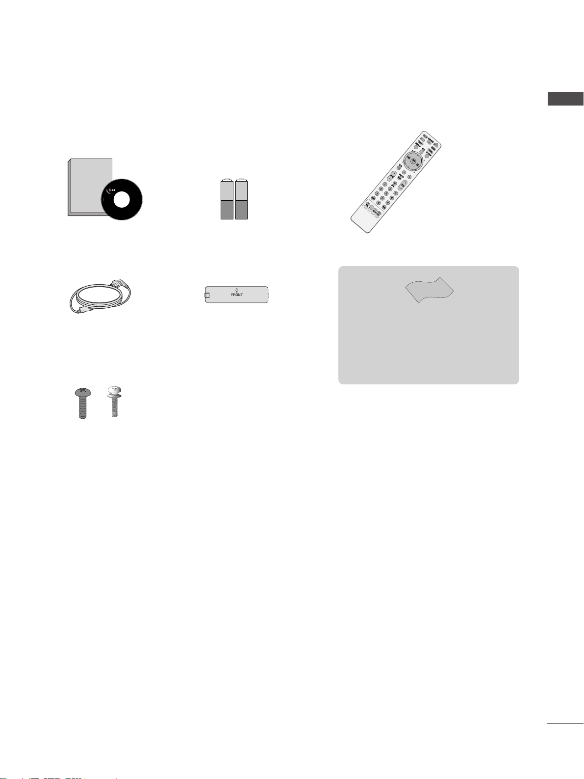
Ensure that the following accessories are included with your TV. If an accessory is missing, please contact the
dealer where you purchased the TV.
Owner’s Manual Batteries Remote Control
Power Cord
Owner's
Manual
Owner’s manual
D
V
D
Bolts for stand assembly
(Refer to p. 6)
(Only 42LG70ED)
Protection Cover
Polishing Cloth
Polishing cloth for use on the screen.
Lightly wipe any stains or fingerprints on the surface
of the TV with the polishing cloth.
Do not use excessive force. This may cause scratching
or discolouration.
x 4 x 4
Page 6

2
CONTENTS
CONTENTS
ACCESSORIES
. . . . . . . . . . . . . . . . . . . . . . . . . . . . . . . . . . . . . . . . . . . . .
1
PREPARATION
Front Panel Controls . . . . . . . . . . . . . . . . . . . . . . . . 4
Back Panel Information . . . . . . . . . . . . . . . . . . . . . . 5
Stand installation . . . . . . . . . . . . . . . . . . . . . . . . . . . . 6
Please set it up carefully so the product
does not fall over . . . . . . . . . . . . . . . . . . . . . . . . . . . 7
Back Cover for Wire Arrangement . . . . . . . . . . . . . . 8
Desktop Pedestal Installation . . . . . . . . . . . . . . . . . . 9
Wall Mount: Horizontal installation . . . . . . . . . . . . . 9
Antenna Connection . . . . . . . . . . . . . . . . . . . . . . . . 10
EXTERNAL EQUIPMENT SETUP
HD Receiver Setup . . . . . . . . . . . . . . . . . . . . . . . . 11
DVD Setup . . . . . . . . . . . . . . . . . . . . . . . . . . . . . . . . 12
VCR Setup . . . . . . . . . . . . . . . . . . . . . . . . . . . . . . . . 15
Other A/V Source Setup . . . . . . . . . . . . . . . . . . . . . 17
External Stereo Aetup . . . . . . . . . . . . . . . . . . . . . . . 17
USB In Setup . . . . . . . . . . . . . . . . . . . . . . . . . . . . . . 18
Digital audio out SETUP . . . . . . . . . . . . . . . . . . . . . 18
PC Setup . . . . . . . . . . . . . . . . . . . . . . . . . . . . . . . . . 19
- Screen Setup for PC Mode . . . . . . . . . . . . . . . 22
WATCHING TV / PROGRAMME CONTROL
Remote Control Key Functions . . . . . . . . . . . . . . . . 25
Turning on the TV . . . . . . . . . . . . . . . . . . . . . . . . . . 27
Programme Selection . . . . . . . . . . . . . . . . . . . . . . . 27
Volume Adjustment . . . . . . . . . . . . . . . . . . . . . . . . . 27
On-Screen Menus Selection and Adjustment . . . . 28
Auto Programme Tuning . . . . . . . . . . . . . . . . . . . . . 29
Manual Programme Tuning (In Digital Mode) . . . . 30
Manual Programme Tuning (In Analogue Mode) . . 31
Programme Edit . . . . . . . . . . . . . . . . . . . . . . . . . . . . 33
Booster . . . . . . . . . . . . . . . . . . . . . . . . . . . . . . . . . . 36
USB Software Upgrade . . . . . . . . . . . . . . . . . . . . . . 37
Selecting the Programme Table . . . . . . . . . . . . . . 38
Key Lock . . . . . . . . . . . . . . . . . . . . . . . . . . . . . . . . . 39
SIMPLINK . . . . . . . . . . . . . . . . . . . . . . . . . . . . . . . . 40
Input Label . . . . . . . . . . . . . . . . . . . . . . . . . . . . . . . 42
AV Mode . . . . . . . . . . . . . . . . . . . . . . . . . . . . . . . . . 43
TIME MACHINE
TimeShift Mode (Pause & Replay of Live TV) . . . 44
Timeshift Initialization . . . . . . . . . . . . . . . . . . . . . . 47
Instant Recording . . . . . . . . . . . . . . . . . . . . . . . . . 48
Manual Record . . . . . . . . . . . . . . . . . . . . . . . . . . . . 50
Schedule List . . . . . . . . . . . . . . . . . . . . . . . . . . . . . 51
Record Quality . . . . . . . . . . . . . . . . . . . . . . . . . . . . 52
To use the USB device . . . . . . . . . . . . . . . . . . . . . 53
Recorded TV Programme List . . . . . . . . . . . . . . . . 54
Photo List . . . . . . . . . . . . . . . . . . . . . . . . . . . . . . . . 57
Music List . . . . . . . . . . . . . . . . . . . . . . . . . . . . . . . . 61
EPG (ELECTRONIC PROGRAMME
GUIDE) (IN DIGITAL MODE)
Switch on/off EPG . . . . . . . . . . . . . . . . . . . . . . . . . 64
Select Programme . . . . . . . . . . . . . . . . . . . . . . . . . . 64
Button Function in NOW/NEXT Guide Mode . . . . . 65
Button Function in 8 Day Guide Mode . . . . . . . . . . 65
Button Function in Date Change Mode . . . . . . . . . . 65
Button Function in Detailed Information Menu . . . . 66
Button Function in Schedule List Mode . . . . . . . . . . 66
Page 7

3
CONTENTS
PICTURE CONTROL
Watching PIP(Picture-in-Picture) . . . . . . . . . . . . . 67
Picture Size (Aspect Ratio) Control . . . . . . . . . . . . 69
Preset Picture Settings
- Picture Mode-Preset . . . . . . . . . . . . . . . . . . . . 71
-
Auto Colour Tone Control (Warm/Medium/Cool)
. . . . 72
Manual Picture Adjustment
- Picture Mode-User option . . . . . . . . . . . . . . . . 73
- Picture Mode-Expert Control . . . . . . . . . . . . . 74
Picture Improvement Technology . . . . . . . . . . . . . . . . . 75
Advanced - Real Cinema . . . . . . . . . . . . . . . . . . . . . 76
Advanced - Black(Darkness) Level . . . . . . . . . . . . . 77
Eye Care . . . . . . . . . . . . . . . . . . . . . . . . . . . . . . . . . 78
Picture Reset . . . . . . . . . . . . . . . . . . . . . . . . . . . . . . 79
SOUND & LANGUAGE CONTROL
Auto Volume Leveler . . . . . . . . . . . . . . . . . . . . . . . . 80
Preset Sound Settings - Sound Mode . . . . . . . . . . 81
Sound Setting Adjustment - User Mode . . . . . . . . . . 82
SRS TruSurround XT . . . . . . . . . . . . . . . . . . . . . . . . . . . 83
Clear Voice . . . . . . . . . . . . . . . . . . . . . . . . . . . . . . . . . . . 84
Balance . . . . . . . . . . . . . . . . . . . . . . . . . . . . . . . . . . 85
TV Speakers On/ Off Setup . . . . . . . . . . . . . . . . . 86
Selecting Digital Audio Out . . . . . . . . . . . . . . . . . 87
Audio Reset . . . . . . . . . . . . . . . . . . . . . . . . . . . . . . . 88
I/II
-
Stereo/Dual Reception (In Analogue Mode Only)
. . . . 89
-
NICAM Reception (In Analogue Mode Only) . . . . . . .
90
- Speaker Sound Output Selection . . . . . . . . . . 90
On-Screen Menu Language
. . . . . . . . . . . . . . . . . . . . . 91
Audio Language selection (In Digital Mode only) . 92
TIME SETTING
Clock Setup . . . . . . . . . . . . . . . . . . . . . . . . . . . . . . . 93
Auto On/ Off Timer Setting . . . . . . . . . . . . . . . . . . 94
Auto Shut-off Setting . . . . . . . . . . . . . . . . . . . . . . . 95
Sleep Timer Setting . . . . . . . . . . . . . . . . . . . . . . . . . 96
APPENDIX
Initializing (Reset to original factory setting) . . . . . 97
Troubleshooting . . . . . . . . . . . . . . . . . . . . . . . . . . . 98
Maintenance . . . . . . . . . . . . . . . . . . . . . . . . . . . . . . 99
Product Specifications . . . . . . . . . . . . . . . . . . . . . 101
Programming the Remote Control . . . . . . . . . . . . 102
Programming Code . . . . . . . . . . . . . . . . . . . . . . . . 103
IR Codes . . . . . . . . . . . . . . . . . . . . . . . . . . . . . . . . 104
Page 8
4
PREPARATION
PREPARATION
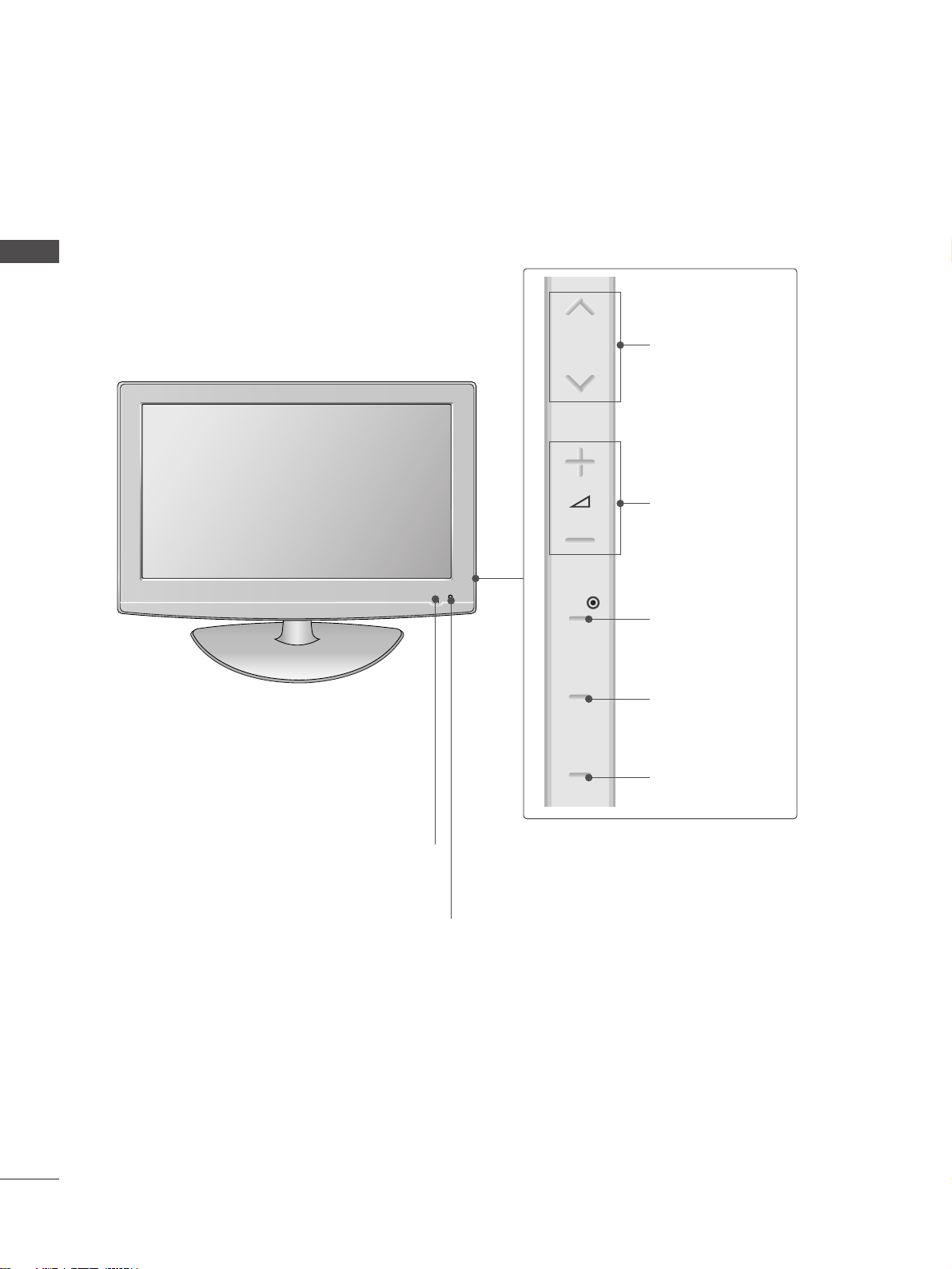
FRONT PANEL CONTROLS
■
Image shown may differ from your TV.
■
If your TV has a protection film attached, remove the film and then wipe the TV with a polishing cloth.
Intelligent Sensor
Adjusts picture according to the surrounding
conditions.
POWER
Remote Control Sensor
Power/Standby Indicator
• illuminates red in standby mode.
• illuminates blue when the TV is switched on.
Note:
You can adjust
PPoowweerr IInnddiiccaattoorr
in
the
OPTION menu.
PROGRAMME
VOLUME
OK
MENU
INPUT
P
OK
MENU
INPUT
Page 9
5
PREPARATION
ANTENNA /
CABLE IN
DIGITAL AUDIO
OUT OPTICAL
S-VIDEO
VIDEO
RS-232C IN
(CONTROL & SERVICE)
RGB(PC)
AUDIO
(RGB/DVI)
RGB IN
AV IN 1
HDMI/DVI IN
2
1
AUDIO OUT
AUDIO
VIDEO
COMPONENT IN
2
1
L/MONO
R
AUDIOAUDIO
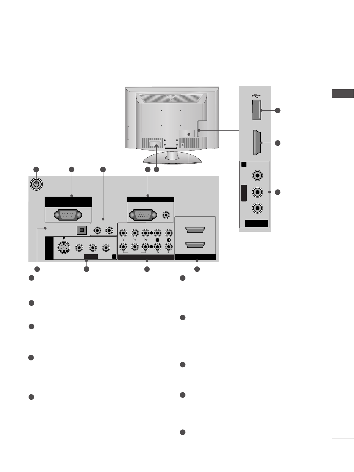
Antenna Input
Connect RF antenna to this jack.
RS-232C IN (CONTROL & SERVICE) PORT
Connect to the RS-232C port on a PC.
Audio Out
Connect an external amplifier or add a subwoofer
to your surround sound system.
RGB IN (PC)
Connect the output from a PC.
AUDIO IN (RGB/DVI)
Connect the audio from a PC or DTV.
Power Cord Socket
This TV operates on an AC power. The voltage is
indicated on the Specifications page. Never
attempt to operate the TV on DC power.
DIGITAL AUDIO OUT OPTICAL
Connect digital audio from various types of
equipment.
Note: In standby mode, these ports do not work.
AV (Audio/Video) IN 1/2
Connect audio/video output from an external
device to these jacks.
S-VIDEO
Connect S-Video out from an S-VIDEO device.
Component Input 1/2
Connect a component video/audio device to
these jacks.
HDMI IN 1/2/3
Connect a HDMI signal to HDMI IN. Or DVI
(VIDEO) signal to HDMI/DVI port with DVI to
HDMI cable.
USB Input
1
2
3
4
5
6
7
8
9
10
R
AV IN 2
L/MONO
R
AUDIO
HDMI IN 3
USB IN
VIDEO
7 8 96
10
9
7
1 2 3 4 5
BACK PANEL INFORMATION
A
Image shown may differ from your TV.
USB IN
HDMI IN 3
AUDIO
VIDEO
Page 10
6
PREPARATION
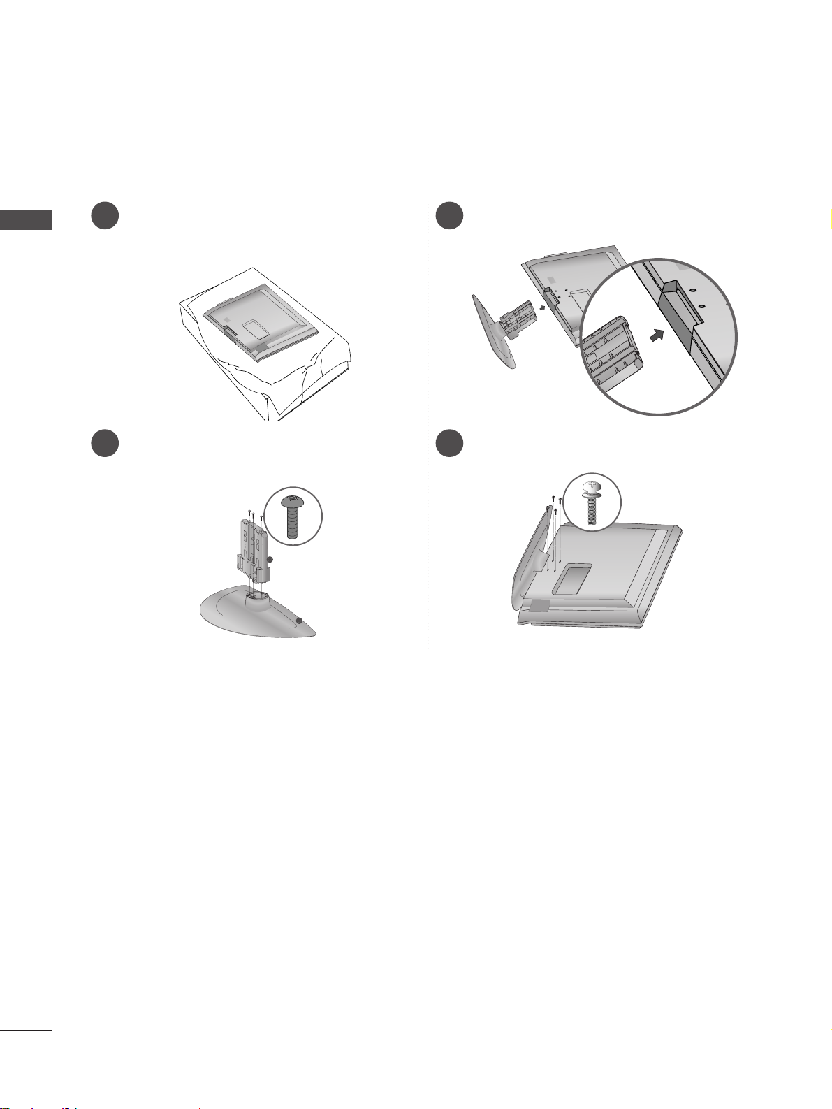
1 3
4
Carefully place the TV screen side down on a
cushioned surface to protect the screen from
damage.
2
Assemble the parts of the
SStt aanndd BBoodd yy
with
the
CCoovv eerr BBaass ee
of the TV.
Assemble the TV as shown.
Fix the 4 bolts securely using the holes in the
back of the TV.
Stand Body
Cover Base
STAND INSTALLATION
(
42LG70ED only
)
PREPARATION
Page 11
7
PREPARATION
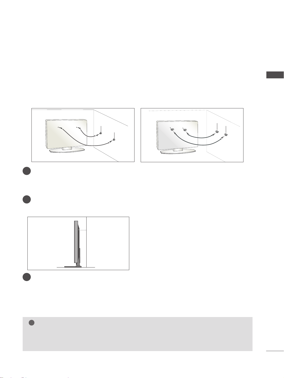
PLEASE SET IT UP CAREFULLY SO THE PRODUCT DOES NOT
FALL OVER.
■
You should purchase necessary components to fix the TV to the wall on the market.
■
Position the TV close to the wall to avoid the possibility of it falling when pushed.
■
The instructions shown below are a safer way to set up the TV, which is to fix it to the wall, avoiding the
possibility of it falling forwards if pulled. This will prevent the TV from falling forward and causing injury. This
will also prevent the TV from damage. Ensure that children do not climb or hang from the TV.
NOTE
!
G
When moving the TV undo the cords first.
G
Use a platform or cabinet strong and large enough to support the size and weight of the TV.
G
To use the TV safely make sure that the height of the bracket on the wall and on the TV is the same.
3
1
2
Use the eye-bolts or TV brackets/bolts to fix the TV to the wall as shown in the picture.
(If your TV has bolts in the eyebolts, loosen these bolts.)
* Insert the eye-bolts or TV brackets/bolts and tighten them securely in the upper holes.
Secure the wall brackets with the bolts on the wall. Match the height of the bracket that is mounted on the
wall.
3
Use a sturdy rope to tie the TV. It is safer to tie the rope so it becomes horizontal between the wall and the
TV.
2
1
2
1
Page 12
8
PREPARATION
PREPARATION
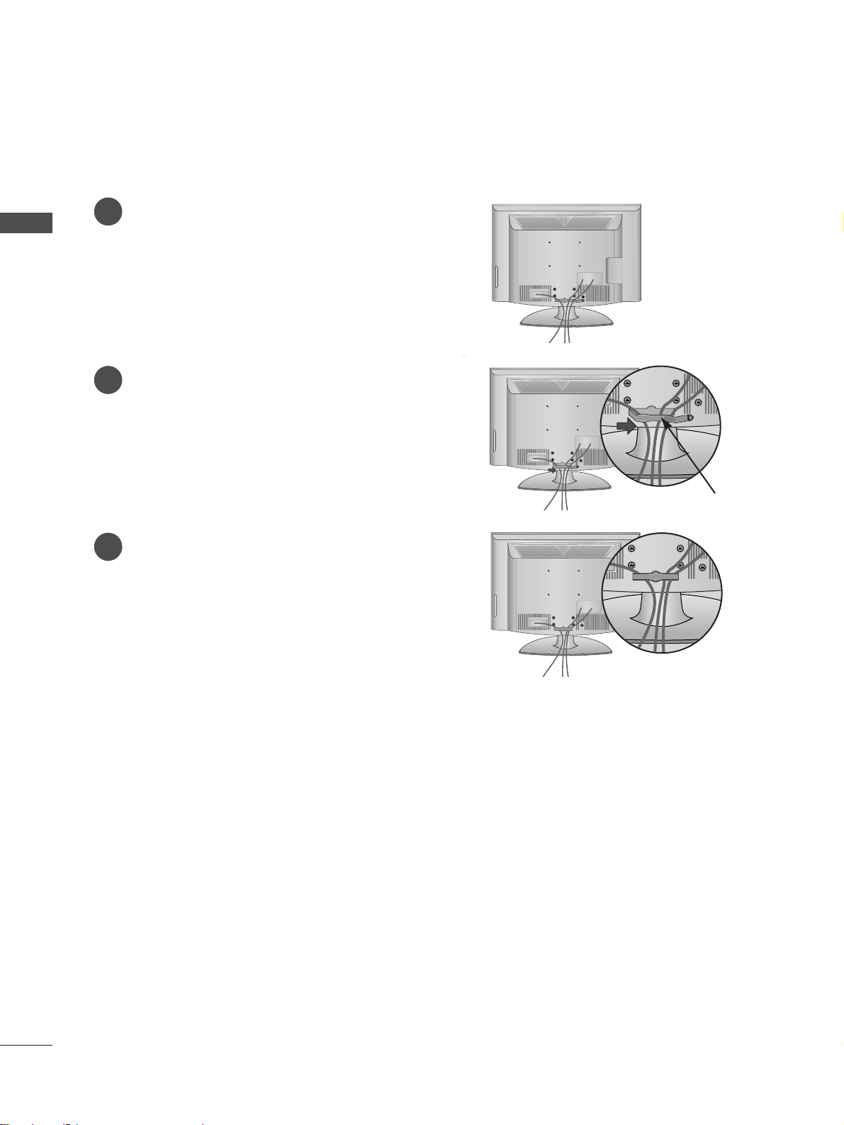
BACK COVER FOR WIRE ARRANGEMENT
Connect the cables as necessary.
To connect additional equipment, see the
External Equipment Setup section of the
manual.
1
Open the
CCAABB LLEE MMAANN AA GGEEMMEENN TT CCLLIIPP
as
shown and manage the cables.
2
CABLE MANAGEMENT CLIP
Fit the
CCAABB LLEE MMAANN AA GGEEMMEENN TT CCLLIIPP
as
shown.
3
Page 13
9
PREPARATION
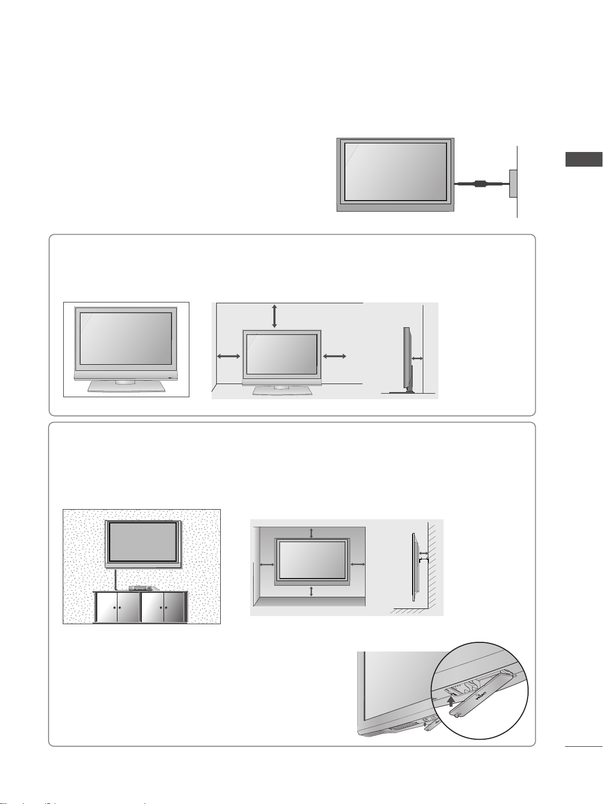
DESKTOP PEDESTAL INSTALLATION
For adequate ventilation allow a clearance of 4” (10cm) all around the TV.
EARTHING
Ensure that you connect the earth wire to prevent possible
electric shock. If grounding methods are not possible, have a
qualified electrician install a separate circuit breaker.
Do not try to earth the TV by connecting it to telephone
wires, lightening rods or gas pipes.
Power Supply
Circuit
breaker
■
The TV can be installed in various ways such as on a wall, or on a desktop etc.
■
The TV is designed to be mounted horizontally.
4 inches
4 inches 4 inches 4 inches
WALL MOUNT: HORIZONTAL INSTALLATION
For adequate ventilation allow a clearance of 4” (10cm) all around the TV. Detailed installation
instructions are available from your dealer, see the optional Tilt Wall Mounting Bracket Installation
and Setup Guide.
4 inches
4 inches
4 inches 4 inches
4 inches
You can remove the stand before installing the TV on a wall mount
by performing the previous stand instructions in reverse. After
removing the stand, install the included
pp rr ootteecctt iioonn ccoovv eerr
over
the hole for the stand.
Insert the
PPRROOTTEECCTTIIOONN CCOOVVEERR
into the TV until clicking sound.
Protection cover
R
Page 14
10
PREPARATION
PREPARATION
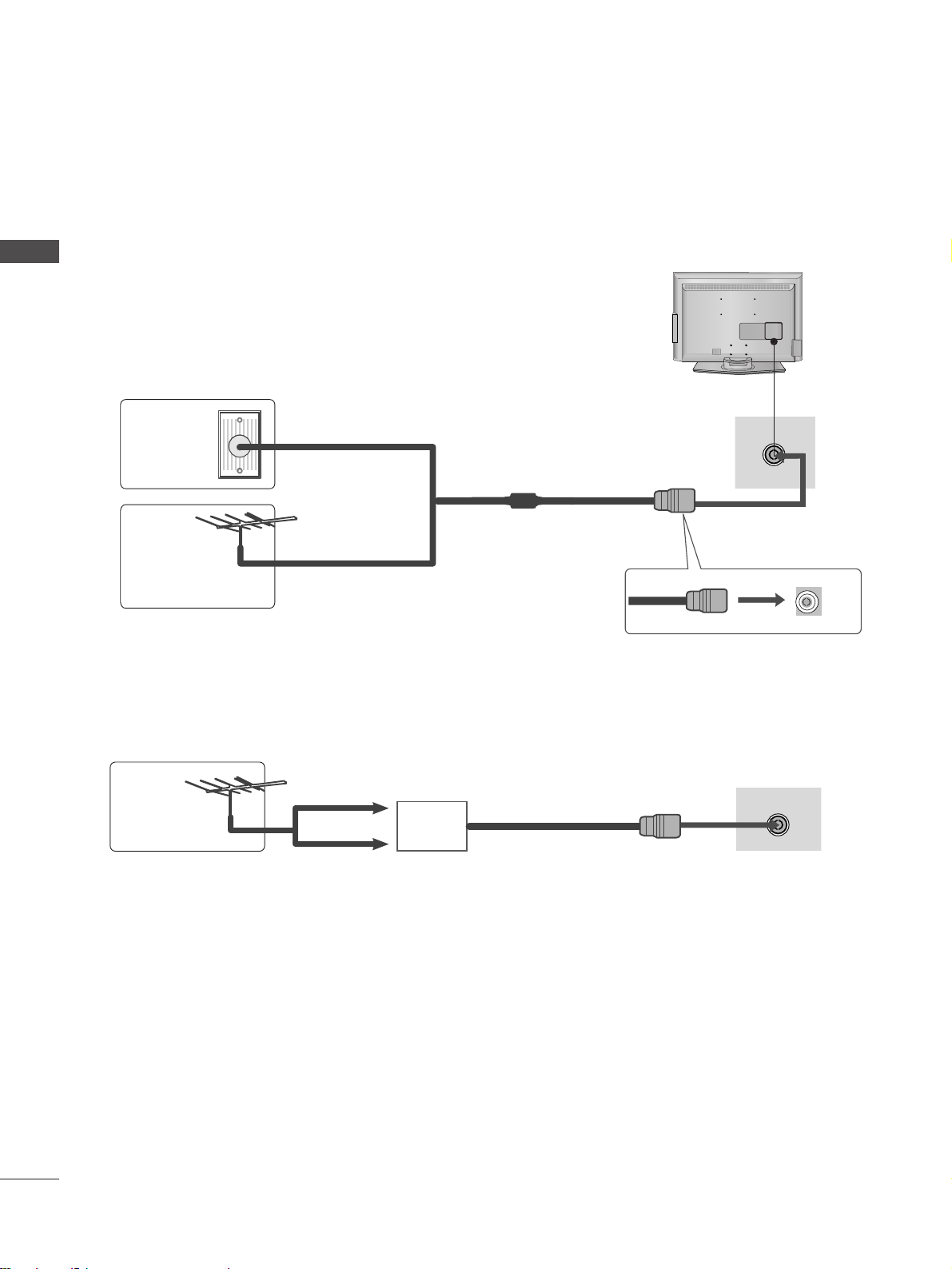
■
For optimum picture quality, adjust antenna direction.
■
An antenna cable and converter are not supplied.
■
To prevent damage do not connect to the mains outlet until all connections are made between the devices.
Multi-family Dwellings/Apartments
(Connect to wall antenna socket)
Single-family Dwellings /Houses
(Connect to wall jack for outdoor antenna)
Outdoor
Antenna
(VHF, UHF)
Wall
Antenna
Socket
RF Coaxial Wire (75 ohm)
ANTENNA CONNECTION
Antenna
UHF
Signal
Amplifier
VHF
■
In poor signal areas, to achieve better picture quality it may be necessary to install a signal amplifier to the
antenna as shown above.
■
If signal needs to be split for two TVs,use an antenna signal splitter for connection.
AV IN 3
L/MONO
R
AUDIO
VIDEO
S-VIDEO
ANTENNA IN
ANTENNA IN
Page 15
11
EXTERNAL EQUIPMENT SETUP
EXTERNAL EQIPMENT SETUP
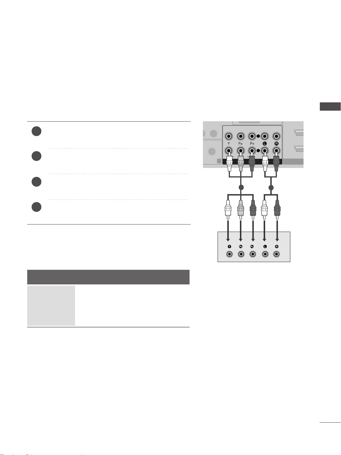
Connect the video outputs (Y, PB, P
R
)
of the digital set
top box to the
CCOOMMPP OONNEENN TT IINN VVIIDDEEOO
jacks on the TV.
Connect the audio output of the digital set-top box to
the
CCOOMMPP OONNEENN TT IINN AAUUDDIIOO
jacks on the TV.
Turn on the digital set-top box.
(
Refer to the owner’s manual for the digital set-top box.
)
Select
CCOO MMPPOONNEENNTT
input source using the
IINNPPUUTT
button on the remote control.
2
3
4
1
HD RECEIVER SETUP
■
To avoid damaging any equipment, never plug in any power cords until you have finished connecting all equipment.
Connecting with a component cable
HDMI
AUDIO
VIDEO
COMPONENT IN
2
1
R
AUDIOAUDIO
L/ MONO
R
AUDIO
1
2
Signal
480i/576i
480p/576p
720p/1080i
10 8 0 p
Component
Yes
Yes
Yes
Yes
HDMI
No
Yes
Yes
Yes
■
This TV can receive Digital RF/Cable signals without an external digital set-top box. However, if you do receive
Digital signals from a digital set-top box or other digital external device, refer to the diagram as shown below.
Page 16
12
EXTERNAL EQUIPMENT SETUP
EXTERNAL EQIPMENT SETUP
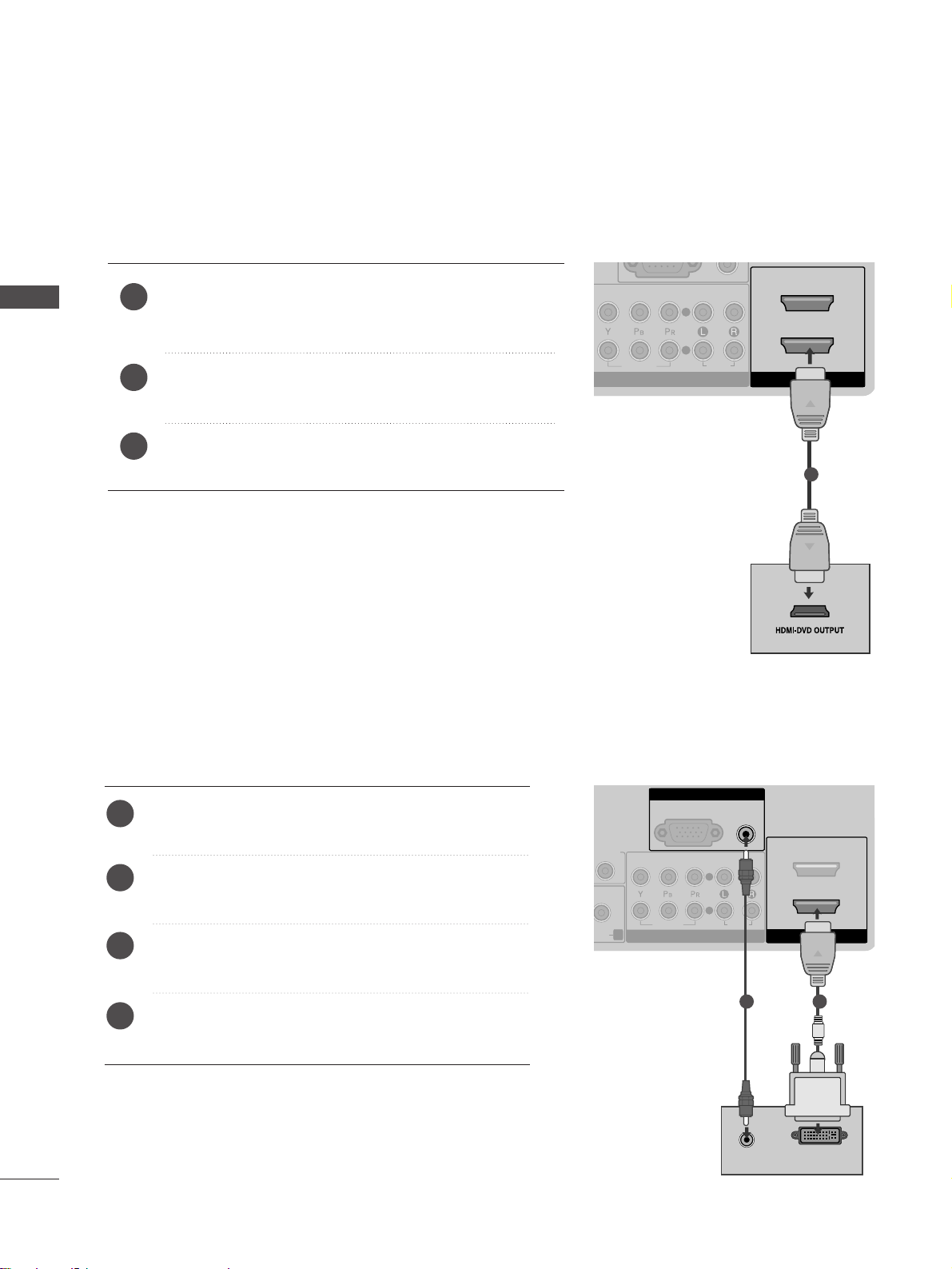
Connect the digital set-top box to
HHDDMMII//DDVVII II NN 11
jack on the TV.
Connect the audio output of the digital set-top box to
the
AAUU DDIIOO ((RRGGBB//DDVV II))
jack on the TV.
Turn on the digital set-top box. (Refer to the owner’s
manual for the digital set-top box.
)
Select HDMI 1 input source using the
IINNPPUU TT
button
on the remote control.
2
3
4
1
Connecting with a HDMI to DVI cable
RGB(PC)
AUDIO
(RGB/DVI)
RGB IN
HDMI/DVI IN
2
1
AUDIO
VIDEO
COMPONENT IN
2
1
R
DIOAUDIO
L/ MONO
R
AUDIO
AUDIO
DVI-PC OUTPUT
12
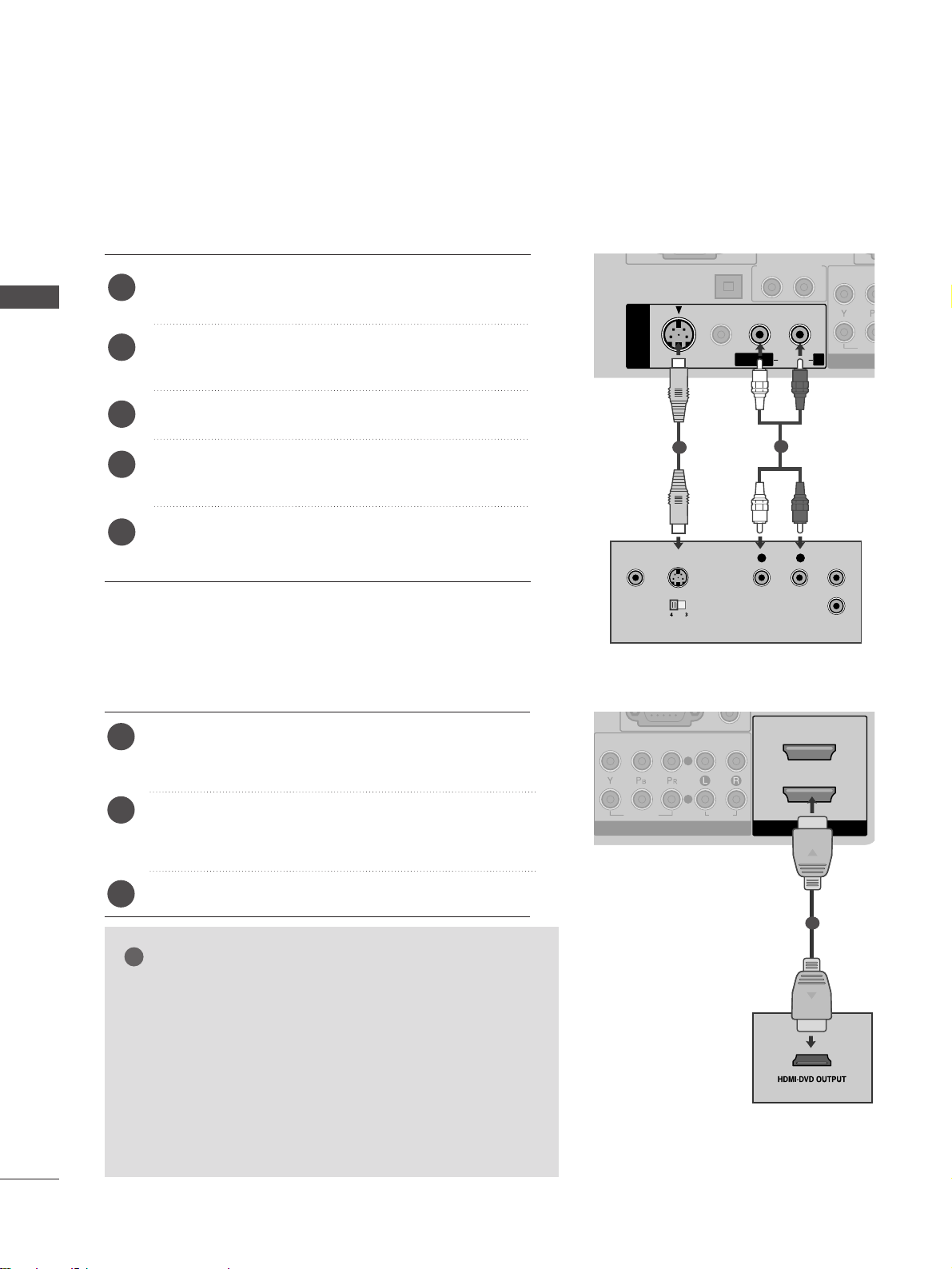
Connecting a set-top box with an HDMI cable
Connect the HDMI output of the digital set-top box to the
HH DDMMII// DDVV II IINN 11,HH DDMMII IINN 22
or
HH DDMMII IINN 33
jack on
the TV.
Turn on the digital set-top box.
(
Refer to the owner’s manual for the digital set-top box.
)
Select HDMI1, HDMI2 or HDMI3 input source using the
IINNPPUUTT
button on the remote control.
2
3
1
HDMI/DVI IN
2
1
AUDIO
VIDEO
COMPONENT IN
2
1
1
Page 17
13
EXTERNAL EQIPMENT SETUP
DVD SETUP
When connecting with a component cable
HDMI/
AUDIO
VIDEO
COMPONENT IN
2
1
R
AUDIOAUDIO
L/ MONO
R
AUDIO
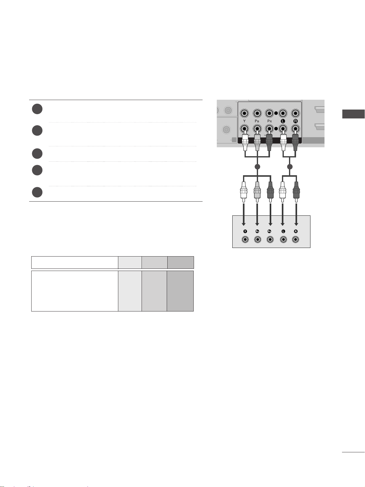
Component Input ports
To achieve better picture quality, connect a DVD player to
the component input ports as shown below.
Component ports on the TV
YPB PR
Video output ports
on DVD player
Y
Y
Y
Y
PB
B-Y
Cb
Pb
P
R
R-Y
Cr
Pr
Connect the video outputs (Y, P
B, PR
)
of the DVD to the
CCOO MM PPOONNEENNTT IINN VVIIDDEEOO
jacks on the TV.
Connect the audio outputs of the DVD to the
CCOO MM PPOONNEENNTT IINN AA UUDDIIOO
jacks on the TV.
Turn on the DVD player, insert a DVD.
Select
CC OOMMPPOONN EENN TT
input source using the
IINNPPUU TT
button
on the remote control.
Refer to the DVD player's manual for operating instructions.
2
3
4
5
1
1 2
Page 18
14
EXTERNAL EQUIPMENT SETUP
EXTERNAL EQIPMENT SETUP
Connecting the HDMI cable
Connect the HDMI output of the DVD to the
HH DDMMII// DDVV II IINN 11, HH DDMMII IINN 22
or
HH DDMMII IINN 33
jack
on the TV.
Select HDMI1, HDMI2 or HDMI3 input source using
the
IINNPPUUTT
button on the remote control.
Refer to the DVD player's manual for operating instructions.
2
3
1
1
GG
The TV can receive video and audio signals simultaneously
when using a HDMI cable.
GG
If the DVD supports Auto HDMI function, the output
resolution of the source device will be automatically set to
1280x720p.
GG
If the DVD does not support Auto HDMI, you must set the
output resolution appropriately.
To get the best picture quality, adjust the output resolution
of the source device to 1280x720p.
NOTE
!
Connecting with a S-Video cable
L/MONO
R
AUDIO
L R
S-VIDEOVIDEO
OUTPUT
SWITCH
ANT IN
ANT OUT
DIGITAL AUDIO
OUT OPTICAL
S-VIDEO
VIDEO
AV IN 1
AUDIO OUT
VID
CO
L/MONO
R
AUDIOAUDIO
Connect the S-VIDEO output of the DVD to the
SS-- VVII DDEEOO
input on the TV.
Connect the audio outputs of the DVD to the
AAUU DD IIOO
input jacks on the TV.
Turn on the DVD player, insert a DVD.
Select AV1 input source using the INPUT button on
the remote control.
Refer to the DVD player's manual for operating
instructions.
2
3
4
5
1
1
2
2
1
VIDEO
COMPONENT IN
AUDIO
2
1
HDMI/DVI IN
Page 19
15
EXTERNAL EQIPMENT SETUP
VCR SETUP
■
To avoid picture noise (interference), allow adequate distance between the VCR and TV.
■
If 4:3 picture format is used for an extended period the fixed images on the sides of the screen may remain
visible.
ANTENNA /
CABLE IN
DIGITAL AUDIO
OUT OPTICAL
S-VIDEO
VIDEO
RS-232C IN
(CONTROL & SERVICE)
RGB(PC)
AUDIO
(RGB/DVI)
RGB IN
AV IN 1
HDMI/DVI IN
2
1
AUDIO OUT
AUDIO
VIDEO
COMPONENT IN
2
1
L/MONO
R
AUDIOAUDIO
OUTPUT
SWITCH
ANT IN
R
S-VIDEO VIDEO
ANT OUT
L
Wall Jack
Antenna
1
2
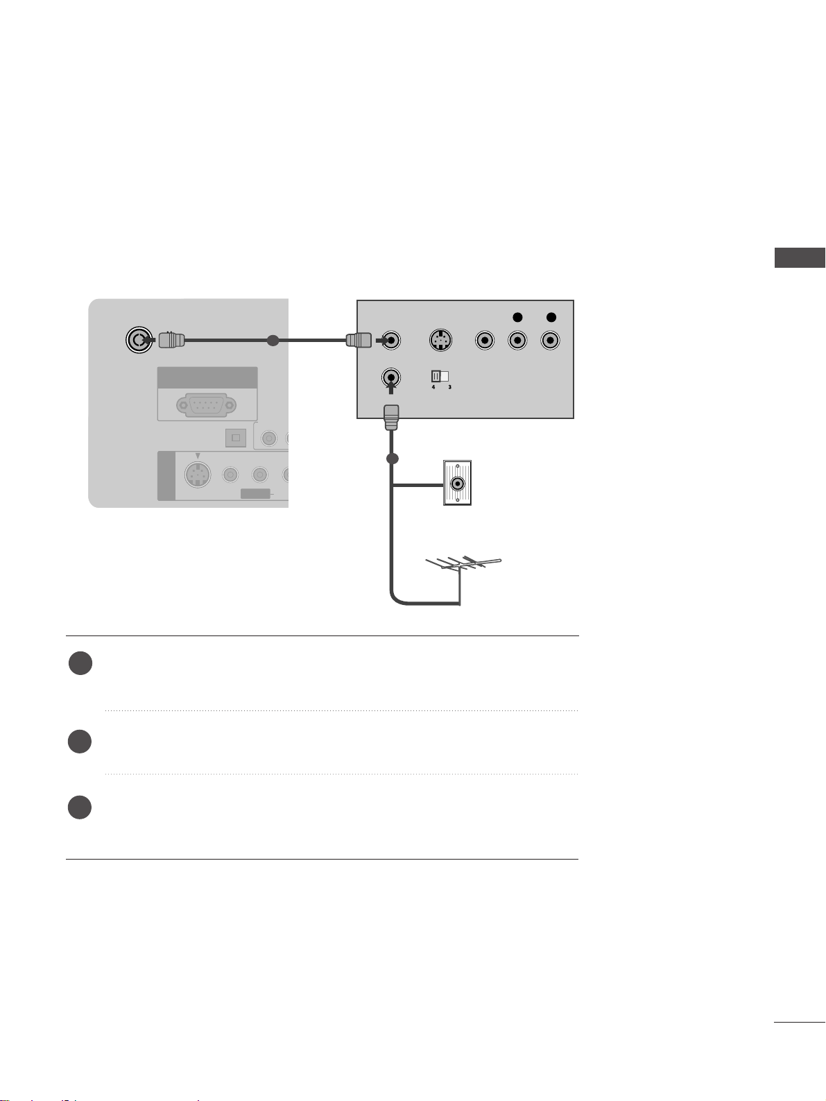
When connecting with a RF Cable
Connect the
AANN TT OOUUTT
socket of the VCR to the
AANNTTEE NNNNAA // CCAABB LLEE IINN
socket on the TV.
Connect the antenna cable to the
AANN TT IINN
socket of the VCR.
Press the PLAY button on the VCR and match the appropriate channel between
the TV and VCR for viewing.
1
2
3
Page 20
16
EXTERNAL EQUIPMENT SETUP
EXTERNAL EQIPMENT SETUP
GG
If both S-VIDEO and VIDEO sockets have been connected to
the S-VHS VCR simultaneously, only the S-VIDEO can be
received.
NOTE
!
L/ MONO
R
AUDIO
L R
S-VIDEOVIDEO
OUTPUT
SWITCH
ANT IN
ANT OUT
DIGITAL AUDIO
OUT OPTICAL
S-VIDEO
VIDEO
AV IN 1
AUDIO OUT
VID
CO
L/MONO
R
AUDIOAUDIO
L/ MONO
R
AUDIO
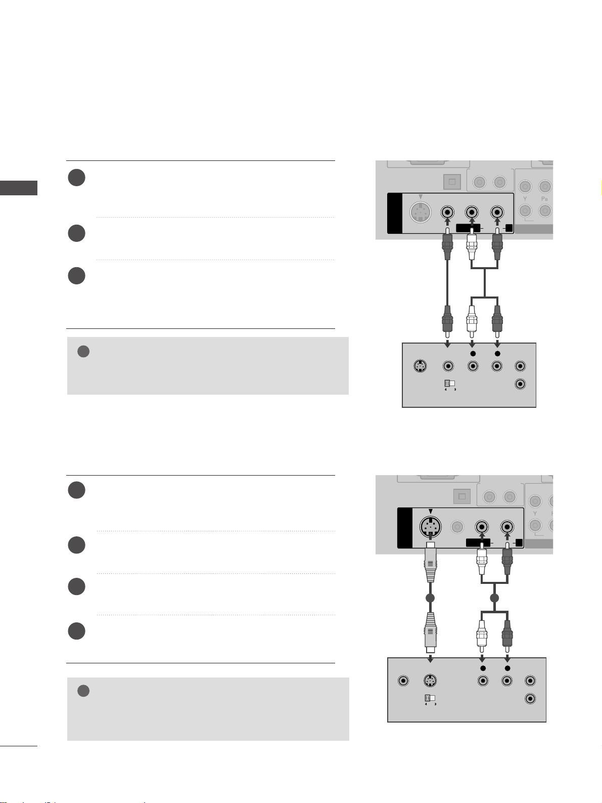
Connecting with a S-Video cable
Connect the S-VIDEO output of the VCR to the S VIDEO input on the TV. The picture quality is improved;
compared to normal composite (RCA cable) input.
Connect the audio outputs of the VCR to the AUDIO
input jacks on the TV.
Insert a video tape into the VCR and press PLAY on the
VCR. (Refer to the VCR owner’s manual.)
Select AV1 input source using the
IINNPPUUTT
button on the
remote control.
2
3
4
1
1 2
Connecting with a RCA cable
L R
S-VIDEO VIDEO
OUTPUT
SWITCH
ANT IN
ANT OUT
DIGITAL AUDIO
OUT OPTICAL
S-VIDEO
VIDEO
AV IN 1
AUDIO OUT
VIDEO
COM
L/MONOMONO
R
AUDIOAUDIO
Connect the
AAUU DD IIOO/VVIIDD EEOO
jacks between TV and
VCR. Match the jack colours (Video = yellow, Audio Left
= white, and Audio Right = red)
Insert a video tape into the VCR and press PLAY on
the VCR. (Refer to the VCR owner’s manual.
)
Select AV1 input source using the
IINNPPUUTT
button on
the remote control.
If connected to
AAVV IINN 22
socket, select
AA VV22
input
source.
1
2
3
GG
If you have a mono VCR, connect the audio cable from the
VCR to the
AAUU DDIIOO LL// MM OONN OO
jack of the TV.
NOTE
!
Page 21
17
EXTERNAL EQIPMENT SETUP
L R
VIDEO
DIGITAL AUDIO
OUT OPTICAL
S-VIDEO
VIDEO
RS-232C IN
(CONTROL & SERVICE)
RGB(PC)
AUDIO
(RGB/DVI)
RGB IN
AV IN 1
AUDIO OUT
AUDIO
VIDEO
COMPONENT IN
2
1
L/MONO
R
AUDIOAUDIO
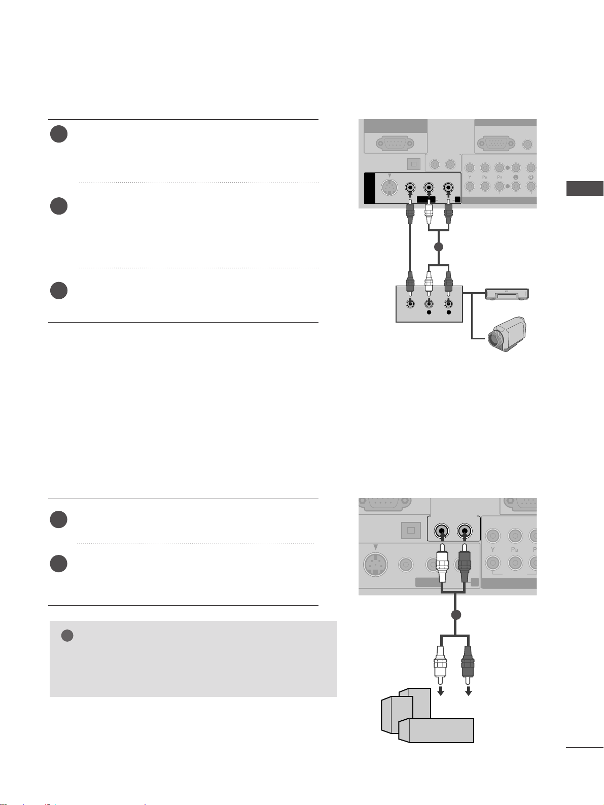
OTHER A/V SOURCE SETUP
Connect the
AAUU DD IIOO/VVIIDD EE OO
jacks between TV and
external equipment. Match the jack colors
. (Video =
yellow, Audio Left = white, and Audio Right = red
)
Select
AA VV11
input source using the
IINNPPUU TT
button on
the remote control.
If connected to
AAVV IINN 22
socket, select
AA VV22
input
source.
Operate the corresponding external equipment.
Refer to external equipment operating guide.
2
3
1
1
Camcorder
Video Game Set
EXTERNAL STEREO SETUP
OPTICAL
S-VIDEO
VIDEO
AUDIO OUT
VIDEO
COMPO
L/L/MONO
R
AUDIOAUDIO
GG
When connecting with external audio equipments, such as
amplifiers or speakers, please turn the TV speakers off.
(
GG
pp.. 8866
)
NOTE
!
Use to connected either an external amplifier, or add a sub-woofer to your surround sound system.
Connect the input jack of the stereo amplifier to the
AAUU DDIIOO OO UUTT
jacks on the TV.
Set up your speakers through your analog stereo
amplifier, according to the instructions provided with
the amplifier.
2
1
11
Page 22
18
EXTERNAL EQUIPMENT SETUP
EXTERNAL EQIPMENT SETUP
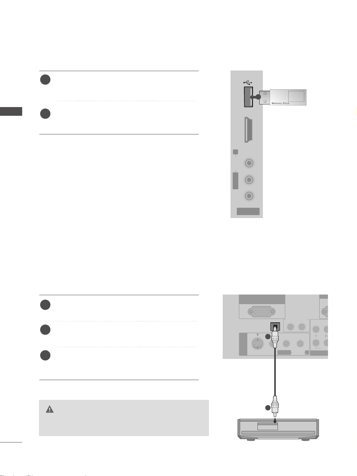
USB IN SETUP
AV IN 2
L/MONOMONO
R
AUDIOAUDIO HDMI IN 3HDMI IN 3 USB INUSB IN
VIDEOVIDEO
1
Connect the USB device to the
UU SS BB IINN
jacks on the
side of TV.
After connecting the
UU SS BB IINN
jacks, you use the
UU SSBB
function. (
GG
pp ..55 33
)
2
1
DIGITAL AUDIO OUT SETUP
- Sending the TV’s audio signal to external audio equipment via the Digital Audio Output (Optical) port.
G
Do not look into the optical output port. Looking at the
laser beam may damage your vision.
CAUTION
DIGITAL AUDIO
OUT OPTICAL
S-VIDEO
VIDEO
RS-232C IN
(CONTROL & SERVICE)
R
AV IN 1
AUDIO OUT
VIDE
CO
L/MONO
R
AUDIOAUDIO
Connect one end of an optical cable to the TV Digital
Audio (Optical)Output port.
Connect the other end of the optical cable to the
digital audio (optical)input on the audio equipment.
Set the “ TV Speaker option - Off ” in the AUDIO
menu.(
G
pp.. 8866
). Refer to the external audio equipment
instruction manual for operation.
2
3
1
1
2
Page 23
19
EXTERNAL EQIPMENT SETUP
RGB(PC)
AUDIO
(RGB/DVI)
RGB IN
HDMI/DVI IN
2
1
AUDIO
VIDEO
COMPONENT IN
2
1
R
L/ MONO
R
AUDIO
AUDIO
DVI-PC OUTPUT
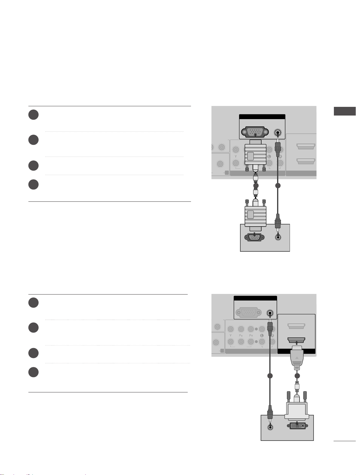
Connecting with a HDMI to DVI cable
Connect the DVI output of the PC to the
HH DDMMII// DDVVII IINN
11
jack on the TV.
Connect the PC audio output to the
AAUU DD IIOO
(( RRGGBB //DDVVII))
jack on the TV.
Turn on the PC and the TV.
Select HDMI 1 input source using the
IINNPPUU TT
button
on the remote control.
2
3
4
1
12
PC SETUP
This TV provides Plug and Play capability, meaning that the PC adjusts automatically to the TV's settings.
Connecting with a D-sub 15 pin cable
RGB(PC)
AUDIO
(RGB/DVI)
RGB IN
HDMI/DVI IN
DIO OUT
AUDIO
VIDEO
COMPONENT IN
2
1
R
AUDIOAUDIO
RGB OUTPUT
AUDIO
1 2
4
Connect the RGB output of the PC to the
RRGGBB II NN
(( PP CC ))
jack on the TV.
Connect the PC audio output to the
AAUU DD IIOO
(( RRGGBB //DDVVII))
jack on the TV.
Turn on the PC and the TV
Select
RR GGBB
input source using the INPUT button on
the remote control.
2
3
1
Page 24

20
EXTERNAL EQUIPMENT SETUP
EXTERNAL EQIPMENT SETUP
NOTE
!
G
To enjoy vivid picture and sound, connect a PC
to the TV.
G
Avoid keeping a fixed image on the TV’s screen
for prolonged periods of time. The fixed image
may become permanently imprinted on the
screen; use a screen saver when possible.
G
Connect the PC to the RGB (PC) or HDMI IN (or
HDMI/DVI IN) port of the TV; change the
resolution.
G
There may be interference relating to resolution,
vertical pattern, contrast or brightness in PC
mode. Change the PC mode to another resolution or change the refresh rate to another rate or
adjust the brightness and contrast on the menu
until the picture is clear. If the refresh rate of the
PC graphic card can not be changed, change the
PC graphic card or consult the manufacturer of
the PC graphic card.
G
The synchronization input waveform for
Horizontal and Vertical frequencies are separate.
G
We recommend using 1024x768, 60Hz for the
PC mode, these should provide the best picture
quality.
G
Connect the signal cable from the monitor output port of the PC to the RGB (PC) port of the
TV or the signal cable from the HDMI output
port of the PC to the HDMI IN (or HDMI/DVI
IN) port on the TV.
G
Connect the audio cable from the PC to the
Audio input on the TV. (Audio cables are not
included with the TV).
G
If using a sound card, adjust PC sound as
required.
G
This TV uses a VESA Plug and Play Solution. The
TV provides EDID data to the PC system with a
DDC protocol. The PC adjusts automatically
when using this TV.
G
DDC protocol is preset for RGB (Analog RGB),
HDMI (Digital RGB) mode.
G
If required, adjust the settings for Plug and Play
functionality.
G
If the graphic card on the PC does not output
analogue and digital RGB simultaneously, connect
only one of either RGB or HDMI IN (or
HDMI/DVI IN) to display the PC output on the
TV.
G
If the graphic card on the PC does output
analogue and digital RGB simultaneously, switch
the TV to either RGB or HDMI; (the other mode
is set to Plug and Play automatically by the TV.)
G
DOS mode may not work depending on the
video card if you use a HDMI to DVI cable.
G
If you use too long an RGB-PC cable, there may
be interference on the screen. We recommend
using under 5m of cable. This provides the best
picture quality.
Page 25
21
EXTERNAL EQIPMENT SETUP
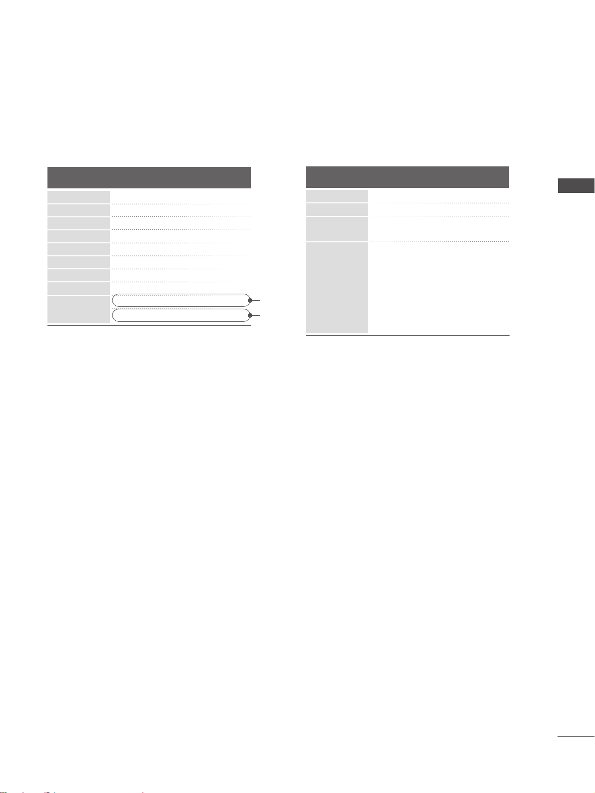
Supported Display Resolution
70.08
59.94
60.31
60.00
59.87
60.00
60.00
60.00
59.934
60
RGB[PC], HDMI[PC] mode
31.469
31.469
37. 879
48.363
47. 776
47. 70
64.00
75.00
66.587
67. 5
Resolution
640x480
800x600
720x400
1024x768
Horizontal
Frequency(kHz)
Vertical
Frequency(Hz)
1280x768
1360x768
1280x1024
1600x1200
1920x1080
HDMI[DTV] mode
60.00
50.00
60.00
50.00
60.00
50.00
24.00
25
30.00
50
60.00
31.50
31.25
45.00
37. 50
33.75
28.125
27.00
28.125
33.750
56.25
67. 5
Resolution
720x480
720x576
1280x720
1920x1080
Horizontal
Frequency(kHz)
Vertical
Frequency(Hz)
RGB[PC]
HDMI[PC]
Page 26
22
EXTERNAL EQUIPMENT SETUP
EXTERNAL EQIPMENT SETUP
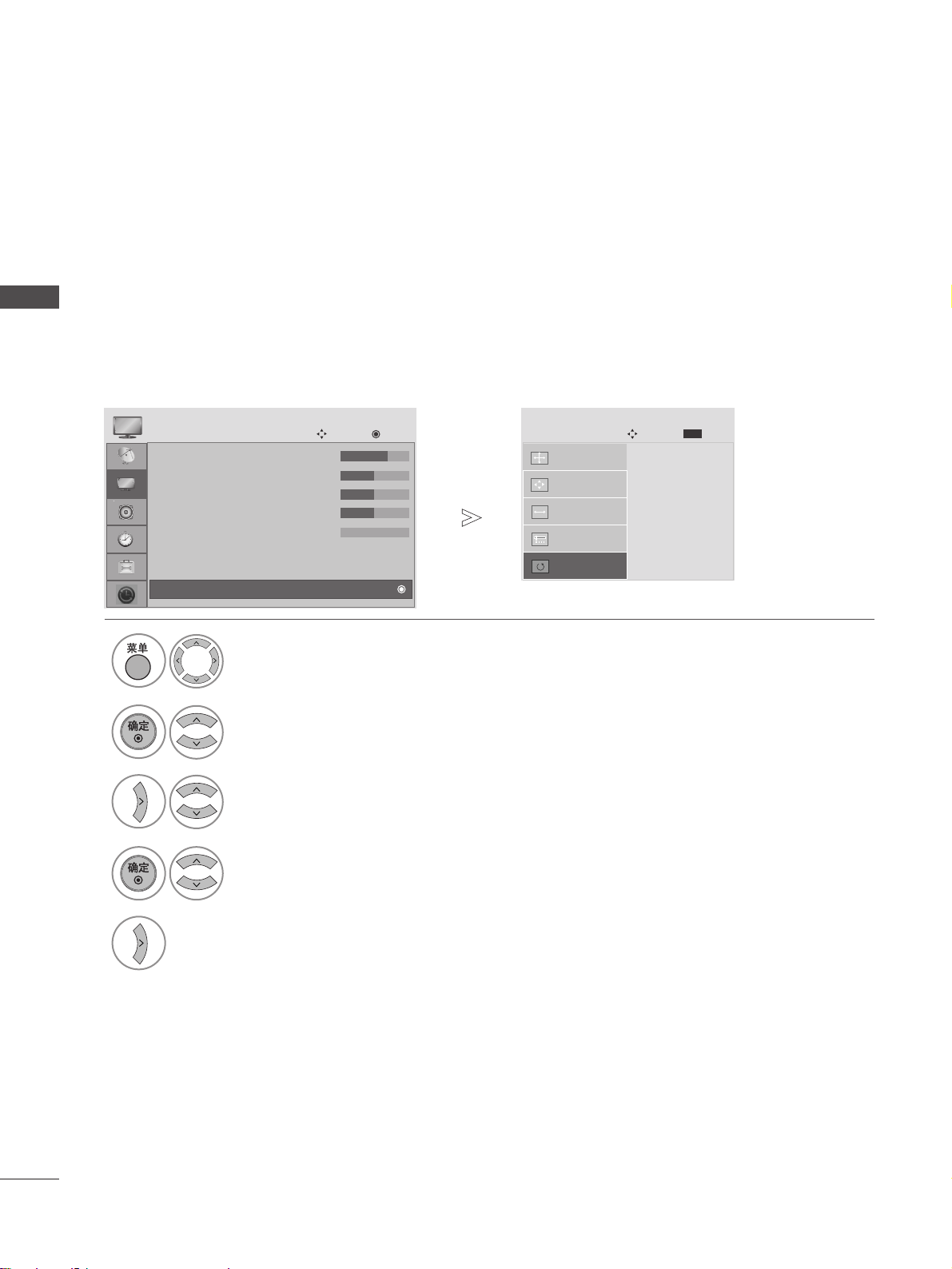
Screen Setup for PC mode
Returns to the default settings Resolution, Position, Size and Phase at the factory.
This function works in the following mode : RGB[PC].
Screen Reset
2
Select PICTURE.
3
Select SCREEN.
4
Select Reset.
5
Run Reset.
• Contrast : 70
• Brightness : 50
• Sharpness : 50
• Colour : 50
• Tint : 0
• Advanced Control
• Picture Reset
PICTURE
Navigation
OK
D
Screen
1
Select TV SETUP.
•
Press the MENU button to return to normal TV viewing.
• Press the RETURN button to move to the previous menu screen.
Initialize Settings.
Position
SCREEN
Navigation
Prev.
MENU
Resolution
Size
Phase
Reset
G
Page 27
23
EXTERNAL EQIPMENT SETUP
If the picture is not clear and especially if characters are still trembling, adjust the picture phase manually.
This function works in the following mode : RGB[PC].
Adjustment for screen Position, Size, Phase
• Contrast : 70
• Brightness : 50
• Sharpness : 50
• Colour : 50
• Tint : 0
• Advanced Control
• Picture Reset
PICTURE
Navigation
OK
D
Screen
• Press the MENU or EXIT button to return to normal TV viewing.
• Press the BACK or RETURN button to move to the previous menu screen.
Position
G
SCREEN
Navigation
Prev.
MENU
Resolution
Size
Phase
Reset
GF
D
E
2
Select PICTURE.
3
Select SCREEN.
4
Select Position, Size or Phase.
5
Make appropriate adjustments.
1
Select TV SETUP.
Page 28
24
EXTERNAL EQUIPMENT SETUP
EXTERNAL EQIPMENT SETUP
To view a normal picture, match the resolution of RGB mode and selection of PC mode.
This function works in the following mode: RGB[PC] mode.
Selecting Resolution
1
Select TV SETUP.
2
Select PICTURE.
3
Select SCREEN.
4
Select Resolution.
• Contrast : 70
• Brightness : 50
• Sharpness : 50
• Colour : 50
• Tint : 0
• Advanced Control
• Picture Reset
PICTURE
Navigation
OK
D
Screen
1024 x 76 8
128 0 x 768
136 0 x 768
Position
SCREEN
Navigation
Prev.
MENU
Resolution
G
Size
Phase
Reset
5
Select the desired resolution.
•
Press the RETURN button to move to the previous menu screen.
Page 29
25
WATCHING TV / PROGRAMME CONTROL
WATCHING TV / PROGRAMME CONTROL
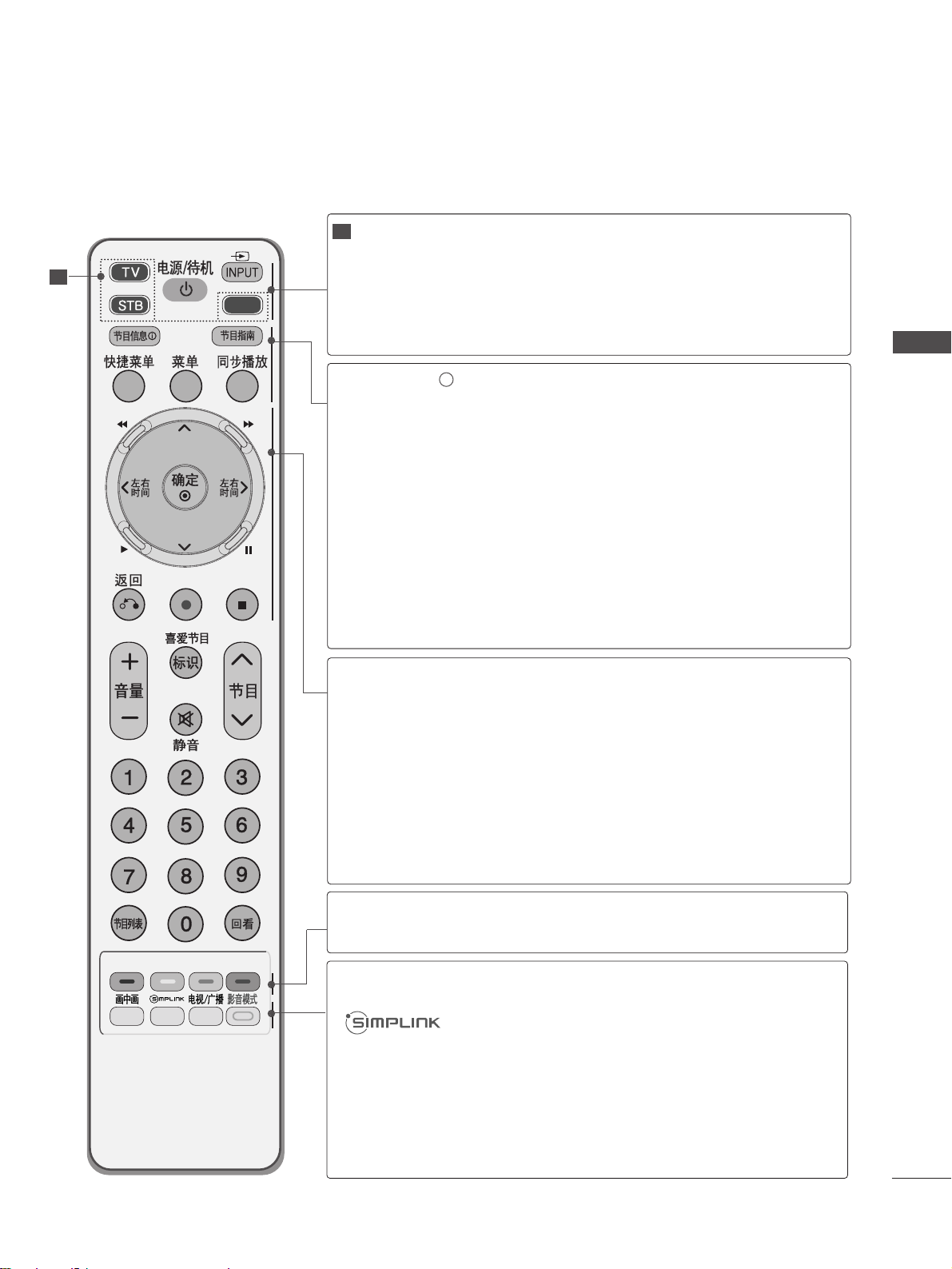
DVD
MODE
POWER
INPUT
Selects the remote operating modes.
Switches the TV on from standby or off to standby.
External input mode rotate in regular sequence.
Switches the TV on from standby.
INFO i
GUIDE
Q. MENU
MENU
LIVE TV
Shows the present screen information.
Shows programme schedule.
Select the desired quick menu source. (Aspect Ratio,
Power Saving(Plasma TV models), Brightness (LCD TV
models), Clear Voice, Picture Mode, Sound Mode, Audio,
Sleep Timer)
Selects a menu.
Clears all on-screen displays and returns to TV viewing
from any menu.
In Delayed mode, the screen returns to Live programme from
TV, AV1, AV2 and Component1, Component2 modes.
THUMBSTICK
(Up/Down/Left
Right)
OK
RETURN
SIMPLINK/ USB
Menu control
buttons.
Allows you to navigate the on-screen menus and adjust
the system settings to your preference.
Accepts your selection or displays the current mode.
Allows the user to move back one step in an interactive
application, EPG or other user interaction function.
Controls SIMPLINK or USB Menu (Photo List and Music
List).
Coloured
buttons
These buttons are used for
PPrr ooggrraa mm mm ee eeddiitt
.
PIP
TV/RAD
AV MODE
Switches the sub picture PIP, DW mode.
See a list of AV devices connected to TV.
When you toggle this button, the Simplink menu appears
at the screen.
Selects Radio, TV, DTV channel.
It helps you select and set images and sounds when connecting AV devices.
1
1
REMOTE CONTROL KEY FUNCTIONS
When using the remote control, aim it at the remote control sensor on the TV.
Page 30
26
WATCHING TV / PROGRAMME CONTROL
WATCHING TV / PROGRAMME CONTROL
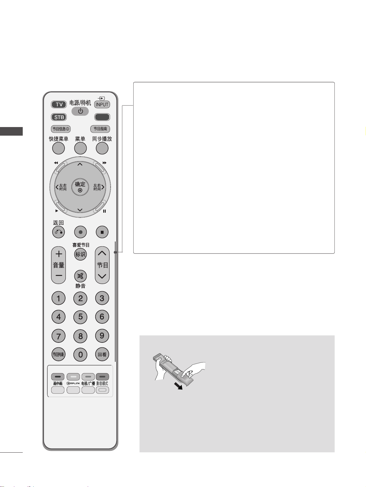
VOLUME UP
/DOWN
MARK
FAV
MUTE
Programme
UP/DOWN
PAGE
UP/DOWN
0~9 number
button
LIST
Q.VIEW
Adjusts the volume.
Check and un-check programmes in the USB Menu.
Displays the selected favourite programme.
Switches the sound on or off.
Selects a programme.
Move from one full set of screen information to the next
one.
Selects a programme.
Selects numbered items in a menu.
Displays the programme table.
Returns to the previously viewed programme.
Installing Batteries
■
Open the battery compartment cover on the back and install the
batteries matching correct polarity (+with +,-with -).
■
Install two 1.5V AAA batteries. Do not mix old or used batteries
with new ones.
■
Close cover.
DVD
Page 31

27
WATCHING TV / PROGRAMME CONTROL
Firstly, connect the power cord correctly.
At this stage, the TV switches to standby mode.
In standby mode to turn TV on, press the
rr
/ I, INPUT or PR
button on the TV or press the POWER, INPUT, D/A, PR or
NUMBER button on the remote control and the TV will switch on.
2
1
TURNING ON THE TV
Initializing se
tup
Note:
a. It will automatically disappear after approx. 40 seconds unless a
button is pressed.
b. Press the RETURN button to change the current OSD to the
previous OSD.
If the OSD (On Screen Display) is displayed on the screen after turning
on the TV, you can adjust the Language, Auto programme tuning.
- When your TV is turned on, you will be able to use its features.
PROGRAMME SELECTION
Press the PR or NUMBER buttons to select a programme
number.
1
VOLUME ADJUSTMENT
Press the VOL + - button to adjust the volume.
If you wish to switch the sound off, press the MUTE button.
You can cancel this function by pressing the MUTE, VOL + -, or I/II
button.
1
Page 32

28
WATCHING TV / PROGRAMME CONTROL
WATCHING TV / PROGRAMME CONTROL
ON SCREEN MENUS SELECTION AND ADJUSTMENT
Your TV's OSD (On Screen Display)may differ slightly from what is shown in this manual.
RECORD INPUT
USB
GUIDE
REC. LIST SIMPLINK TV SETUP
SCHEDULE
1
Display each menu.
2
Select a menu item.
3
Move to the pop up menu.
•
Press the MENU button to return to normal TV viewing.
• Press the RETURN button to move to the previous menu screen.
Page 33

29
WATCHING TV / PROGRAMME CONTROL
Auto tuning
Manual tuning
Programme Edit
Booster : On
USB Software Upgrade
SETUP
Navigation
OK
Auto tuning
Use this to automatically find and store all available programmes.
When you start auto programming, all previously stored service information will be deleted.
AUTO PROGRAMME TUNING
• If you wish to keep on auto tuning select YES
using the button. Then, press the OK
button. Otherwise select NO.
Select SETUP.
3
Select Auto Tuning.
4
Select Ye s .
5
Run Auto tuning.
2
Select TV SETUP.
1
• Press the MENU button to return to normal TV viewing.
• Press the RETURN button to move to the previous menu screen.
Auto tuning
Manual tuning
Programme Edit
Booster : On
USB Software Upgrade
SETUP
Navigation
OK
Auto tuning
All service-information will be updated.
Continue?
Ye s No
Page 34

30
WATCHING TV / PROGRAMME CONTROL
WATCHING TV / PROGRAMME CONTROL
Auto tuning
Manual tuning
Programme Edit
Booster : On
USB Software Upgrade
SETUP
Navigation
OK
Manual tuning
Manual Tuning lets you manually add a programme to your programme list.
MANUAL PROGRAMME TUNING (IN DIGITAL MODE)
• If you want to keep on manual tuning, select
YES using the button. Then, press the
OK button. Otherwise select NO.
Select SETUP.
3
Select Manual Tuning.
4
Select DTV.
5
Select the desired channel number.
Select channel type and RF-channel
number.
VHF CH.
Bad Normal Good
FF
DTV
GG
30
Add
Close
2
Select TV SETUP.
1
• Press the MENU button to return to normal TV viewing.
• Press the RETURN button to move to the previous menu screen.
Auto tuning
Manual tuning
Programme Edit
Booster : On
USB Software Upgrade
SETUP
Navigation
OK
Manual tuning
Page 35

31
WATCHING TV / PROGRAMME CONTROL
Auto tuning
Manual tuning
Programme Edit
Booster : On
USB Software Upgrade
SETUP
Navigation
OK
Manual tuning
Manual Tuning lets you manually tune and arrange the stations in whatever order you desire.
MANUAL PROGRAMME TUNING (IN ANALOGUE MODE)
• BG : PAL B/G (Asia/New Zealand/M.East/Africa/Australia)
I : PAL I/II (Hong Kong/South Africa)
DK : PAL D/K (East Europe/China/Africa/CIS)
M : (USA/Korea/Philippines)
• To store another channel, repeat steps 5 to 9.
Select SETUP.
3
Select Manual Tuning.
4
Select TV.
5
Select the desired programme
number on.
6
Select a TV system.
7
Select V/UHF or Cable.
9
Select Store.
or
8
Select the desired
channel number.
123
456
7809
or
Storage
FF
TV
GG
30
System
DK
Band
V/UHF
Channel
Fine
FF GG
FF GG
Search
1
Name
C 02
Store
Close
2
123
456
7809
Select TV SETUP.
1
• Press the MENU button to return to normal TV viewing.
• Press the RETURN button to move to the previous menu screen.
Auto tuning
Manual tuning
Programme Edit
Booster : On
USB Software Upgrade
SETUP
Navigation
OK
Manual tuning
Page 36

32
WATCHING TV / PROGRAMME CONTROL
WATCHING TV / PROGRAMME CONTROL
Normally fine tuning is only necessary if reception is poor.
A Fine Tuning
5
Select Fine.
6
Fine tune for the best picture
and sound.
7
Select Store.
Save.
You can assign a station name with five characters to each programme number.
A Assigning a station name
Select Name.
6
Select the position and make
your choice of the second character, and so on.
You can use an the alphabet
AA
to ZZ, the number 00to 99, +/ -,
and blank.
7
Select Store.
Save.
8
8
• Press the MENU button to return to normal TV viewing.
• Press the RETURN button to move to the previous menu screen.
Select SETUP.
3
Select Manual Tuning.
4
Select TV.
2
Select TV SETUP.
1 5
Select SETUP.
3
Select Manual Tuning.
4
Select TV.
2
Select TV SETUP.
1
Page 37

33
WATCHING TV / PROGRAMME CONTROL
When a programme number is skipped, it means that you will be unable to select it using PR button during
TV viewing.
If you wish to select the skipped programme, directly enter the programme number with the NUMBER buttons or
select it in the Programme edit menu
This function enables you to skip the stored programmes.
In some countries it is possible to move a programme number by using the YELLOW button only.
PROGRAMME EDIT
3
Select Programme Edit.
4
Enter the Programme Edit.
C 011
Favourite List
Favourite Pr. Change
TV DTV Radio
0 C 01 1 C 04
2
C 05 3 C 07
6 C 07 8 C 09
9 C 08 14 C 03
24 C 04 50 C 06
24 C 05 84 C 02
24 C 03 86 C 05
87 C 01 88 C 07
E
D
ReturnNavigation
SkipMoveDelete
D
F G
E
Page Change
• Press the MENU button to return to normal TV viewing.
• Press the RETURN button to move to the previous menu screen.
Auto tuning
Manual tuning
Programme Edit
Booster : On
USB Software Upgrade
SETUP
Navigation
OK
Programme Edit
Select SETUP.
2
Select TV SETUP.
1
+
-
Page 38

34
WATCHING TV / PROGRAMME CONTROL
WATCHING TV / PROGRAMME CONTROL
A Skipping a programme number
Select a programme number to be skipped.
2
BLUE
BLUE
Turn the skipped programme number to blue.
3
BLUE
BLUE
Release the skipped programme.
1
• When a programme number is skipped it means
that you will be unable to select it using the
PR button during normal TV viewing.
• If you wish to select a skipped programme, directly
enter the programme number with the NUMBER
buttons or select it in the programme edit or EPG.
A Selecting favourite programme
Select your favourite programme
number.
1
• It will automatically include the selected
programme into your favourite programme list.
(IN DTV/RADIO MODE)
Page 39

35
WATCHING TV / PROGRAMME CONTROL
This function enables you to delete or skip the stored programmes.
You can also move some channels to other programme numbers.
A Selecting a Favourite Programme
Select your favourite programme number.
• The selected programme will be added to the
favourite programme list.
IN TV MODE
A Deleting a programme
Select a programme number to be deleted.
2
RED
RED
Turn the deleted programme number to red.
3
RED
RED
Release the deleted programme.
1
A Skipping a programme number
Select a programme number to be skipped.
2
BLUE
BLUE
Turn the skipped programme number to blue.
3
BLUE
BLUE
Release the skipped programme.
• The selected programme is deleted, all the fol-
lowing programmes are shifted up one
A Moving a programme
Select a programme number to be moved.
Turn the moved programme number to YELLOW.
3
YELL
YELLOOWW
Release the moved programme.
• When a programme number is skipped it means
that you will be unable to select it using the PR
button during normal TV viewing.
• If you wish to select a skipped programme, directly
enter the programme number with the NUMBER buttons or select it in the programme edit or EPG.
2
YELL
YELLOOWW
1
1
1
Page 40

Auto tuning
Manual tuning
Programme Edit
Booster : On
USB Software Upgrade
SETUP
Navigation
OK
Booster : On
36
WATCHING TV / PROGRAMME CONTROL
WATCHING TV / PROGRAMME CONTROL
If reception is poor, selectBooster to On.
When the signal is strong, select “Off”.
BOOSTER
Select TV SETUP.
3
Select Booster.
4
Select On or Off.
5
Save it.
1
Off
On
On
Select SETUP.
2
• Press the MENU button to return to normal TV viewing.
• Press the RETURN button to move to the previous menu screen.
Auto tuning
Manual tuning
Programme Edit
Booster : On
USB Software Upgrade
SETUP
Navigation
OK
Booster : On
Page 41

37
WATCHING TV / PROGRAMME CONTROL
Auto tuning
Manual tuning
Programme Edit
Booster : On
USB Software Upgrade
SETUP
Navigation
OK
USB Software Upgrade
USB Software Upgrade means software can be downloaded by USB memory.
USB SOFTWARE UPGRADE
- During Progress of a USB Software Upgrade, please note the following:
• Power to the TV must not be interrupted.
• The TV must not be switched off.
• After Software Update, you can confirm the updated software version in Diagnostics menu.
3
Select USB Software Upgrade.
4
Select On or Off.
• If you select On, a user
confirm message box will be
displayed to notify that new
software is found.
Auto tuning
Manual tuning
Programme Edit
Booster : On
USB Software Upgrade
SETUP
Navigation
OK
USB Software Upgrade
All of channel information will be updated.
Continue?
Ye s No
Select SETUP.
2
Select TV SETUP.
1
Page 42

38
WATCHING TV / PROGRAMME CONTROL
WATCHING TV / PROGRAMME CONTROL
You can check which programmes are stored in the memory by displaying the programme table.
SELECTING THE PROGRAMME TABLE
display the PROGRAMME LIST.
1
Select a programme.
2
Switch to the chosen programme number.
1
A Displaying programme LIST
A Selecting a programme in the programme list
•
You may find some blue programmes. These
have been set up to be skipped by auto
programming or in the programme edit mode.
•
Some programmes with the channel number
shown in the programme LIST indicate there is
no station name assigned.
1
Turns the pages.
2
Return to normal TV viewing.
A Paging through a programme list
1
Display the Favourite Programme table.
A
Displaying the favourite programme table
From the programme you are currently
watching, the mode will change from
TV to DTV to Radio.
Page 43

39
WATCHING TV / PROGRAMME CONTROL
Language : English
Input Label
SIMPLINK : Off
Key Lock : Off
Power Indicator
Factory Reset
OPTION
Navigation
OK
Key Lock : Off
Language : English
Input Label
SIMPLINK : Off
Key Lock : Off
Power Indicator
Factory Reset
OPTION
Navigation
OK
The TV can be set so that the remote control is required to control it. This feature can be used to prevent
unauthorized viewing.
KEY LOCK
Select TV SETUP.
3
Select Key Lock.
4
Select On or Off.
5
Save it.
1
Key Lock : Off
Off
On
Off
• In Key Lock ‘On’, if the TV is turned off, press
the
r / I, INPUT, PR button on the TV or
POWER, INPUT, D/A TV, PR or NUMBER
buttons on the remote control.
• With the Key Lock On, the display ‘ Key Lock
On ’ appears on the screen if any button on the
front panel is pressed while viewing the TV.
Select OPTION.
2
• Press the MENU button to return to normal TV viewing.
• Press the RETURN button to move to the previous menu screen.
Page 44

40
WATCHING TV / PROGRAMME CONTROL
WATCHING TV / PROGRAMME CONTROL
This function operates only with devices with the SIMPLINK logo.
Please check the SIMPLINK logo.
This allows you to control and play other AV devices connected to the display through HDMI cable without
additional cables and settings.
If you require the SIMPLINK menu, select “On”.
SIMPLINK function is not supported by HDMI IN 3 input.
•
Press the MENU button to return to normal TV viewing.
• Press the RETURN button to move to the previous menu screen.
Language : English
Input Label
SIMPLINK : Off
Key Lock : Off
Power Indicator
Factory Reset
OPTION
Navigation
OK
SIMPLINK : Off
Language : English
Input Label
SIMPLINK : Off
Key Lock : Off
Power Indicator
Factory Reset
OPTION
Navigation
OK
Select TV SETUP.
3
Select SIMPLINK.
4
Select On or Off.
5
Save it.
1
SIMPLINK : Off
Off
On
Off
Select OPTION.
2
Page 45

41
WATCHING TV / PROGRAMME CONTROL
TV
VCR
HDD Recorder
Speaker
F
TV Speaker
G
DISC
OKF G Change Device
NOTE
!
GG
Connect the HDMI/DVI IN or HDMI IN terminal of the TV to the rear terminal (HDMI terminal) of the
SIMPLINK device with the HDMI cable.
GG
After connecting the HDMI terminal for the home theatre with the SIMPLINK function using the above
method, connect the DIGITAL AUDIO OUT terminal on the back of the TV to the DIGITAL AUDIO IN terminal on the back of the SIMPLINK device with the OPTICAL cable.
GG
When operating an external device with SIMPLINK, press the TV button from the MODE buttons on the
remote control.
GG
When you switch the Input source using the INPUT button on the remote control, you can stop the operation of a device controlled by SIMPLINK
GG
When you select or operate a media device with home theater function, the speaker automatically switches
to home theater speaker (HT speaker).
DDiisscc ppllaayybbaacckk
Control connected AV devices by pressing the
,
OK, G, A,
ll ll
, FFand GGbuttons.
(TheÔ button does
not provide such functions.)
DDiirreecc tt PPllaayy
After connecting AV devices to the TV, you can directly control the devices and play media without additional settings.
SSeelleecctt AAVV ddeevviicc ee
Enables you to select one of the AV devices connected to the TV and operate it.
PP ooww eerr ooffff aallll ddeevviicceess
When you switch off the TV, all connected devices are turned off.
SSwwiittcchh aauuddiioo--oouutt
Offers an easy way to switch audio-out.
SSyynncc PPoowweerr oonn
When you play the connected AV device, TV will automatically turn on.
**
A device, which is connected to the TV through a HDMI cable but does not support SIMPLINK, does not provide this
function.
SIMPLINK Functions
Selected Device
When no device is connected (displayed in gray)
When a device is connected
(displayed in bright colour)
1
2
3
4
5
SIMPLINK Menu
Press the button and then OK button to select the desired SIMPLINK source.
TTVV vviieeww iinngg ::
Switch to the previous TV programme
regardless of the current mode.
DDIISSCC pp ll aayybbaacckk ::
Select and play connected discs.
When multiple discs are available, the titles of discs are
conveniently displayed at the bottom of the screen.
VVCCRR ppllaayybb aacckk ::
Play and control the connected
VCR.
HHDDDD RR eecc oorrdd ii nn gg ss ppllaayy bbaacckk ::
Play and control
recordings stored in HDD.
AAuuddiioo OOuutt ttoo HHoomm ee t
thheeaatteerr//AAuuddiioo OOuutt ttoo TTVV::
Select Home theater or TV speaker for Audio Out.
1
2
3
4
5
Page 46

42
WATCHING TV / PROGRAMME CONTROL
WATCHING TV / PROGRAMME CONTROL
Selects a label for each input source which is in use.
INPUT LABEL
• Press the MENU button to return to normal TV viewing.
• Press the RETURN button to move to the previous menu screen.
Language : English
Input Label
SIMPLINK : Off
Key Lock : Off
Power Indicator
Factory Reset
OPTION
Navigation
OK
Input Label
Language : English
Input Label
SIMPLINK : Off
Key Lock : Off
Power Indicator
Factory Reset
OPTION
Navigation
OK
Select TV SETUP.
3
Select Input Label.
4
Select the source.
5
Select the label.
1
Input Label
Select OPTION.
2
RGB-PC
HDMI1
HDMI2
HDMI3
AV1
FF GG
AV2
Component1
Component2
Close
Page 47

43
WATCHING TV / PROGRAMME CONTROL
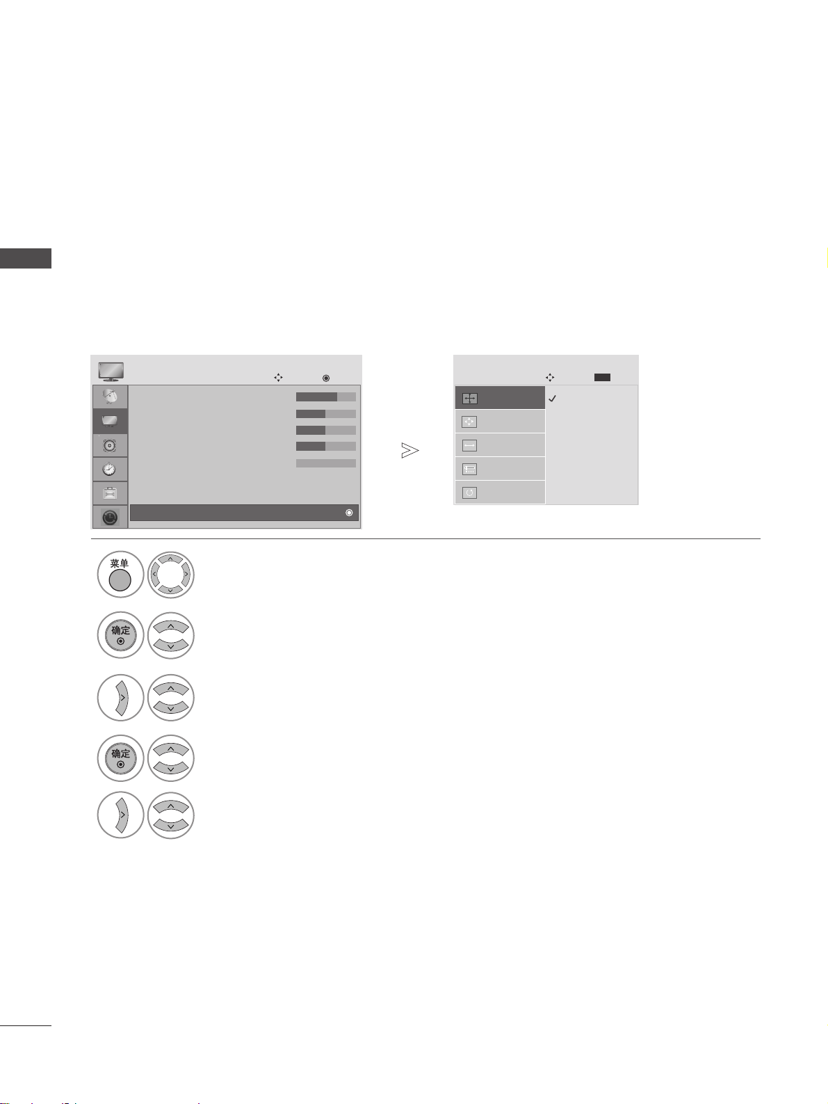
AV MODE
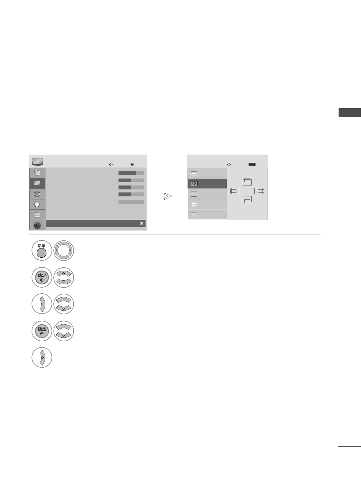
You can select the optimal images and sounds when connecting AV devices to external input.
• If you select Cinema Mode in AV mode, Cinema
mode will be selected both for Picture Mode and
Sound Mode in PICTURE menu and AUDIO menu
respectively.
•
If you select “Off” in AV mode, the picture and
image which you initially set will be selected.
Off Cinema
Game Sport
Select the desired source.
Page 48

44
TIME MACHINE
TIME MACHINE
Timeshift Mode : On
Record Quality : Best
Recorded List
Schedule List
Manual Record
Timeshift Initialization
DVR
Navigation
OK
TIMESHIFT MODE (PAUSE & REPLAY OF LIVE TV)
This function allows the unit to automatically record live TV and make it available for viewing at any time.
With the TimeShift turned on, you may pause and rewind normal TV viewing at any time without missing any of the
live broadcast.
(TimeShift Mode and Recording functions may not work if the signal strength is weak.)
4
Select On or Off.
• Press the MENU button to return to normal TV viewing.
• Press the RETURN button to move to the previous menu screen.
Timeshift Mode : On
Timeshift Mode : On
Record Quality : Best
Recorded List
Schedule List
Manual Record
Timeshift Initialization
DVR
Navigation
OK
Timeshift Mode : On
3
Select DVR.
Select Timeshift Mode.
2
Select TV SETUP.
1
Off
On
On
Page 49

45
TIME MACHINE
1 2 3 4
LIVE
LIVE
After selecting TimeShift Mode On, press the
OOKK
button.
■
As soon as Timeshift starts, a progress bar indicating the
current recording status is displayed in the bottom of the
screen.
■
Press the
EEXXIITT
button to hide the ‘Progress Bar’ or press
the
OOKK
button to display the 'Progress Bar'.
■
This function is preserved even change a programme on progressing the Timeshift.
When finishing the Timeshift function, enter the
TIME
MACHINE menu and turn TimeShift Mode Off.
NOTE
!
GG
TIME MACHINE : A device which records and
plays broadcast programme contents onto a hard
disk in set or SET TOP BOX.
GG
In order to save hard-disk space, nothing is saved
when there is no signal.
GG
The total storage space of the hard-disk is 160
GB. 4 GB minimum is reserved for TimeShift
Mode.
GG
When turning power on, it may take up to a maximum of 3 minutes to initialize the HDD.
GG
The Recording function will not initiate for a
copy-protected programme.
GG
Because an analogue broadcast is converted to a
digital signal, video which contains rapid movement may show "cross stripes". This happens
when the analog signal is compressed and then
restored in the digital signal. The unit will attempt
to reduce excessive picture interference.
GG
When using the PIP/DW mode, Timeshift is
stopped.
GG
TimeShift Mode is available in TV, AV1, AV2,
Component(480i/480p/576i/576p/720p/1080i)
mode.
GG
TimeShift Mode is not available for Audio only
channels.
GG
Maximum recording file size is up to 16GB(3Hr).
2
1
TThhee ‘‘PPrrooggrreessss BBaarr’’??
This function indicates what TIME MACHINE
reviewing is possible,a current on-screen and live
broadcasting position.
Status of current displayed video.
C
urrent save time.
15 minute intervals from TimeShift Mode start
time. (Total - one hour).
Indicates current TimeShift Mode position.
1
2
3
4
Using the TimeShift Mode function
Page 50

46
TIME MACHINE
TIME MACHINE
DELA
DELA
YED
YED
When playing,
repeatedly, press the
RR EE WW
((
FFFF
))
button to speed up
FFFF
->
FFFFFF
->
FFFFFFFF
->
FFFFFFFFFF->FFFFFFFFFFFF
.
repeatedly, press the
FF FF
((
GGGG
))
button to speed up
GGGG
->
GGGGGG
->
GGGGGGGG
->
GGGGGGGGGG
->
GGGGGGGGGGGG
.
■
Pressing these buttons repeatedly increases the fast forward/reverse speed.
During playback, press the
PPaa uu ssee((IIII
))
button.
■
Still screen is displayed.
■
Repeatedly press the
PPaa uu ssee((IIII
))
button to advance frame by frame.
■
Press the
PPaa uu ssee((IIII
))
button and then use the
FF FF ((
GGGG
))
button for slow
motion (the
II
GG
icon is displayed.)
■
Press the
PPaa uu ssee((IIII
))
button and then use the
FF FF ((
FFFF
))
button for slow
motion (the
FF
II
icon is displayed.)
■
When using the FFor
GG
button during playback a cursor indicating the posi-
tion can be viewed on the screen.
Press the
PPLL AAYY
((
GG
))
button to return to normal playback.
If you want to return to the current live broadcast, press the LIVE TV button.
FFFF /GGGG
FF /GG
LIVE TV
PPLL AAYY
((
GG
))
IIII
Using the TimeShift Mode function, play
- When in timeshift mode, the following options are available.
Indicates that the current broadcast and displayed video differ.
Using the remote control
You can shift playback to any point within the recorded programme
Play Pause
■
When pressing the OObutton delaying Timeshift, Timeshift
is dumped. And delayed time is recording.
Page 51

47
TIME MACHINE
TIMESHIFT INITIALIZATION
Erases all programmes and initializes the hard disk.
Timeshift Mode : On
Record Quality : Best
Recorded List
Schedule List
Manual Record
Timeshift Initialization
DVR
Navigation
OK
4
Start Timeshift Initialization.
Timeshift Initialization
Timeshift Mode : On
Record Quality : Best
Recorded List
Schedule List
Manual Record
Timeshift Initialization
DVR
Navigation
OK
Timeshift Initialization
3
Select DVR.
Select Timeshift Initialization.
2
Select TV SETUP.
1 • if you select Yes, this message is displayed.
• When completing, this message is displayed.
HDD formatting is started
HDD formatting is completed.
Initialize Timeshift?
Initializing will delete all programmes and timer recording lists.
Ye s No
ii
Page 52

48
TIME MACHINE
TIME MACHINE
INSTANT RECORDING
Select the programme you wish to record and then press the
OO
button.
During recording is displayed. Use this
feature to record up to 2 hours of programming.
If you wish to stop recording, press the
AA
button.
You can increase or decrease the recording time by pressing the
OO
button while
recording. After pressing the
OO
button, press the
FF / GG
buttons repeatedly to
increase or decrease the recording time. Each time you press
FF / GG
button
the recording duration changes as shown below.
Instant Record
Use this function to record the programme you are watching on the main screen.
This function records the currently displayed programme.
++1100 mm iinn-->> ++2200mm ii nn-->> ++3300mm ii nn-->> ++4400mm ii nn-->> ++5500mm ii nn-->> ++6600mm ii nn
-- 1100mmii nn-->> --2200 mm ii nn-->> --3300 mm ii nn-->> --4400 mm i
inn-->> --5500 mm ii nn-->> --6600 mm ii nn
NNoo CChhaa nn gg ee
■
While recording, if you press the
AA
button less than 10
seconds after recording started, this message is displayed.
■
If you press the AAbutton more than 10 seconds after
recording started, this message is displayed.
2
3
1
Recording is completed.
Recording is not completed.
Recording time must exceed 10 seconds.
REC
REC
Page 53

49
TIME MACHINE
NOTE
!
GG
When recording, if the available storage space is
not sufficient, the recording will automatically
Stop.
GG
Recordings of less than 10 seconds will not be
saved.
GG
To save disk space while recording broadcasts, no
data will be saved if there is no signal.
GG
The recording function will not initiate for a copyprotected programme.
GG
The displayed time may differ slightly from the
actual time.
GG
When there is no signal or a film source is being
viewed, the displayed time may differ slightly from
the actual time.
GG
Timeshift recording is not possible with copy-protected programmes.
GG
When a poor quality external source is recorded
(for example old VHS tape) the quality of the
recording will not be optimal.
GG
Programmes are stored separately according to
the colour system used. e.g. PAL/NTSC.
GG
Manual Recording available time is maximum 4
hours and minimum 5 minutes.
The extra recording time added to the existing setting
equals the final recording time.
After adjusting the recording time, select
OOKK
. The Status
bar will be displayed.
■
Press the
EEXXIITT
button to hide the Status bar. Press the
OOKK
button to display the Status bar.
Recording stops when the selected duration is reached or
when you press the
AA
button.
Although recording has stopped, the Timeshift feature
remains active.
Elapsed recording time
Total recording duration
4
5
3
Stop recording due to copy protection.
00:00
Recording Option
Recording Time
00:00~02:00 (0 Min Recorded)
No Change
Set Duration
OK
Cancel Stop Record
REC
REC
Page 54

50
TIME MACHINE
TIME MACHINE
MANUAL RECORD
This function is easy to register to reserved recording.
When Manual Recording, the default sound of the set is stored.
GG
IInnppuutt
: Select the input source from the TV,
AV1, AV2, Component1/2(480i/576i).
GG
PPRR
: Select either the current programme or a
scanned programme.
GG
DD aattee
: You can select a date up to one month in
advance.
GG
TTiimm ee //DDuurraatt iioonn
: Ensure you have set correctly.
GG
FF rr eeqq uu eennccyy
: Choose among Once, Daily and
Weekly.
Timeshift Mode : On
Record Quality : Best
Recorded List
Schedule List
Manual Record
Timeshift Initialization
DVR
Navigation
OK
4
6
Enter the Manual Record.
5
Select the
IInnpp uu tt,PPRR,DD aattee,TTii mm ee
,
DD uu rr aattiioonn,FF rr eeqq uu eennccyy
.
Manual Record
3
Select DVR.
Select Manual Record.
2
Select TV SETUP.
1
• Press the RETURN button to move to the previous menu screen.
Page 55

51
TIME MACHINE
SCHEDULE LIST
This function is used to show scheduled recordings.
You can store up to 6 programmes.
Timeshift Mode : On
Record Quality : Best
Recorded List
Schedule List
Manual Record
Timeshift Initialization
DVR
Navigation
OK
4
Enter the Schedule List.
5
Select a recorded programme.
Schedule List
3
Select DVR.
Select Schedule List.
2
Select TV SETUP.
1
• Press the RETURN button to move to the previous menu screen.
Page 56

52
TIME MACHINE
TIME MACHINE
When recording analogue broadcasts and external input signals, the Record Quality can be selected.
This function is not available while a recording is taking place.
RECORD QUALITY
Timeshift Mode : On
Record Quality : Best
Recorded List
Schedule List
Manual Record
Timeshift Initialization
DVR
Navigation
OK
4
Select the
BBee ss tt,HH iigghh
or
NNoorrmmaa ll
.
Record Quality : Best
Timeshift Mode : On
Record Quality : Best
Recorded List
Schedule List
Manual Record
Timeshift Initialization
DVR
Navigation
OK
Record Quality : Best
3
Select DVR.
Select Record Quality.
2
Select TV SETUP.
1
• Press the RETURN button to move to the previous menu screen.
Best
High
Normal
Best
Page 57

53
TIME MACHINE
Precautions when using the USB device
GG
Only a USB storage device is recognizable.
GG
If the USB storage device is connected through a USB hub, the device is not recognizable.
GG
A USB storage device using an automatic recognition programme may not be recognized.
GG
A USB storage device which uses its own driver may not be recognized.
GG
The recognition speed of a USB storage device may depend on each device.
GG
Please do not turn off the TV or unplug the USB device when the connected USB storage device is working.
When such device is suddenly separated or unplugged, the stored files or the USB storage device may be damaged.
GG
Please do not connect the USB storage device which was artificially maneuvered on the PC. The device may
cause the product to malfunction or fail to be played. Never forget to use only a USB storage device which has
normal music files or image files.
GG
Please use only a USB storage device which was formatted as a FAT32 file system provided with the Windows
operating system. In case of a storage device formatted as a different utility programme which is not supported
by Windows, it may not be recognized.
GG
Please connect power to a USB storage device which requires an external power supply. If not, the device may
not be recognized.
GG
Please connect a USB storage device with cable is offered by USB maker. If connected with cable is not offered
by USB maker or an excessively long cable, the device may not be recognized.
GG
Some USB storage devices may not be supported or operated smoothly.
GG
If the name of a folder or file is too long, it will not be displayed or recognized.
GG
Please up the important file because a data of USB device may be damaged. Data management is consumer's
responsibility and in consequence the manufactures does not cover the product bearing data damage.
When connecting the USB device
When you connect a USB device, this screen is displayed, automatically.
In USB device, you can not add a new folder or delete the existing folder.
When removing the USB device
Connect the USB device to the
UU SSBB IINN
jacks on the side of TV.
3
Select
PPHHOOTTOO LLIISS TT orMMUU SSIICC LLIISSTT
1
USB memory stick
PHOTO LIST MUSIC LIST
Select
UUSSBB EEjjeecctt
.
Select the USB EJECT menu before removing the
USB device.
2
1
2
• It doesn’t support USB HDD
• This TV Supports on JPEG and MP3.
TO USE THE USB DEVICE
Page 58

54
TIME MACHINE
TIME MACHINE
RECORDED TV PROGRAMME LIST
You can view the recorded programme list at a glance.
This function is also available in the TIME MACHINE menu.
Press the
TTIIMMEE MMAACCHHIINNEE
button to display
HHOOMMEE
menu.
Use the
DD
//
EE
button to select
RReeccoorrddeedd TTVV
and then use
the
OOKK
or
GG
button.
1
Screen Components
Free Space
Page 2/3
No Marked
Recor
Recor
ded TV
ded TV
Input : AV1
Date : Thu. Jun14 2007
Duration : 2 min
Quality : High
No Title AV1 Thu.Jun14 10 : 07
No Title AV1 Thu.Jun14 09 : 20
HIGH
NORMAL
11h 24m
22h 46m
Menu
Navigation Popup Menu Move Page Mark Exit
Free Space
Page 2/3
No Marked
Recor
Recor
ded TV
ded TV
Menu
Navigation
Popup Menu Move Page Mark Exit
Input : AV1
Date : Thu. Jun14 2007
Duration : 2 min
Quality : High
No Title AV1 Thu.Jun14 10 : 07
No Title AV1 Thu.Jun14 09 : 20
HIGH
NORMAL
11h 24m
22h 46m
Usable HDD space
Current page/Total pages
Marked title or programme
Corresponding buttons on the
remote control
1
3
4
2
32
1
4
Page 59

55
TIME MACHINE
Recorded programme Selection and Popup Menu
The recorded programme stored in the internal HDD or the
USB storage device can be played.
The preview recorded list is shown above.
Use the
PPRR ++// --
button for page up/down navigation.
Use the
MMAARR KK
button to delete from the list. A is dis-
played next to the preview window if an item is marked.
Use
DD
//
EE
button to navigation the appropriate Recorded
programme, then press the
OO KK
button to open the Pop-up
Menu.
2
1
3
<HDD Backup process screen>
■
if you press the AAbutton, this message is displayed.
Do you really want to cancel the backup?
Yes No
GG
PPllaayy
: Begin playback of selected recorded programme.
GG
MMaarrkk AAllll
: mark all recorded programmes on the screen.
GG
UUnnmmaarrkk AAllll
: Change marked recorded programmes to
unmarked recorded programmes.
GG
DDeelleettee
: Delete the selected recorded programmes.
GG
RReennaammee
: Edit recorded programme title.
GG
CCoo ppyy ttoo UUSSBB HHDD DD
: Copies the recorded programme
in the internal HDD to the USB storage device.
It is activated only when a USB HDD available for backup
is connected.
USB Backup is started.
Copying to USB HDD (1/1)
Close Stop
75%
1
2
Free Space
Page 2/3
No Marked
Recor
Recor
ded TV
ded TV
Menu
Navigation
Popup Menu Move Page Mark Exit
Input : AV1
Date : Thu. Jun14 2007
Duration : 2 min
Quality : High
No Title AV1 Thu.Jun14 10 : 07
No Title AV1 Thu.Jun14 09 : 20
HIGH
NORMAL
11h 24m
22h 46m
3
Free Space
Page 2/3
No Marked
Recor
Recor
ded TV
ded TV
Menu
Navigation
Popup Menu Move Page
Input : AV1
Date : Thu. Jun14 2007
Duration : 2 min
Quality : High
No Title AV1 Thu.Jun14 10 : 07
No Title AV1
HIGH
NORMAL
11h 24m
22h 46m
AV1
10:07~10:09
Play
Mark All
Delete
Rename
Copy to USB HDD
Cancel
Page 60

56
TIME MACHINE
TIME MACHINE
■
When 'Yes’ is selected, the backup is cancelled and is
converted back to input mode. If more than two files
are transferred, the transferred file is stored, and the
backup operations on the files in progress of transferring and scheduled for backup are cancelled.
■
When ‘No’ is selected, returns to the backup process
screen.
GG
CCaa nn ccee ll
: Close the Pop-up menu.
Repeatedly, press the
EEXXIITT
button to return to TV viewing
or press the
TTIIMMEE MMAACCHHIINNEE
button to return to the
HHoommee
menu.
■
If the HDD has a problem performing a recording related
function, this message is displayed.
■
If the temperature is below zero (0°), a warning message is
displayed and you will not be able to use the TIME
MACHINE functions.
4
4
HDD initialisation is in progress.
Cannot operate TIME MACHINE at low
temperature.
While backup is being
performed in the background, the status of
the copy progress can
be checked by pressing
the ‘OK’ button.
Copying 0%( 1/1 )
Page 61

57
TIME MACHINE
Screen Components
The On Screen Display may be different from your TV. Images are an example to assist with the TV operation.
Moves to upper level file
Current page/Total pages
Total number of marked photos
Usable USB memory
Corresponding buttons on the
remote control
1
3
4
5
2
PHOTO LIST
PHOTO(*.JPEG) supporting file
Baseline: 10928
x
6144
• You can play JPEG files only.
• Only baseline scan is supported among JPEG(SOF0, SOF1 only).
• Non-supported files are displayed in the form of bitmap.
USB Device
Page 2/3
No Marked
PHOTO LIST
Up Folder
Free Space 150MB
Navigation Option Page Change Mark Exit
1366x768, 125KB
KY101
KY102
JMJ001
JMJ002
JMJ003
JMJ004
KY103
KY104
KY105
JMJ005
JMJ006
JMJ007
JMJ008
Up Folder
2 3 4
5
1
Select
UUSSBB
.
Select
UU SSBB PPhhoottoo LLiisstt
.
2
Drive1
1
MARK
RETURN
Page 62

58
TIME MACHINE
TIME MACHINE
Photo Selection and PopUp Menu
USB Device
Page 2/3
No Marked
PHOTO LIST
Up Folder
Free Space 150MB
Navigation O ption Page Change Mark Exit
1366x768, 125KB
KR101
KR102
JMJ001
JMJ002
JMJ003
JMJ004
KR103
KR104
KR105
JMJ005
JMJ006
JMJ007
JMJ008
Up Folder
USB Device
Page 2/3
No Marked
PHOTO LIST
Up Folder
Free Space 150MB
Navigation O ption Page Change Mark Exit
1366x768, 125KB
KR101
KR102
JMJ001
JMJ002
JMJ003
JMJ004
KR103
KR104
KR105
JMJ005
JMJ006
JMJ007
JMJ008
Up Folder
1366x768, 125KB
View
Mark All
Delete
Close
GG
VViieeww
: Display the selected item.
GG
MMaarrkk AAllll
: Mark all photos on the screen.
GG
UUnnmmaarrkk AAllll
: Deselect all marked photos.
GG
DDeelleettee
: Delete the selected photo item.
GG
CClloossee
: Close the pop-up menu.
Select the target folder or drive.
Select the desired photos.
2
Show the PopUp menu.
3
1
• Use the
PPRR
button to navigation in the
photo page.
• Use the
MMAARRKK
button to mark or unmark a
photo. When one or more photos are marked,
you can view individual photos or a slide show
of the marked photos. If no photos are marked,
you can view all photos individually or all photos in the folder in a slide show.
Drive1
Drive1
4
Select the desired PopUp menu.
• Press the
RR EE TTUURR NN
button to return to normal TV viewing.
MARK RETURN
MARK
RETURN
Page 63

59
TIME MACHINE
Set up the menu in Full-Sized Screen
You can change the settings to display photos stored on a USB device, on a full-sized screen.
Detailed operations are available on full-sized photo view screen.
•
Use the
PPRR
button to navigation in the
photo page.
USB Device
Page 2/3
No Marked
PHOTO LIST
Up Folder
Free Space 150MB
Navigation O ption Page Change Mark Exit
1366x768, 125KB
KR101
KR102
JMJ001
JMJ002
JMJ003
JMJ004
KR103
KR104
KR105
JMJ005
JMJ006
JMJ007
JMJ008
Up Folder
1366x768, 125KB
View
Mark All
Delete
Close
The aspect ratio of a photo may change the size of the photo displayed on the screen in full size.
Press the
RREETT UURR NN
button to move to the previous menu screen.
1/17
Slideshow BGM Delete Option Close
USB Device
Page 2/3
No Marked
PHOTO LIST
Up Folder
Free Space 150MB
Navigation O ption Page Change Mark Exit
1366x768, 125KB
KR101
KR102
JMJ001
JMJ002
JMJ003
JMJ004
KR103
KR104
KR105
JMJ005
JMJ006
JMJ007
JMJ008
Up Folder
Drive1
Drive1
Select the target folder or drive.
Select the desired photos.
Show the PopUp menu.
5
Select
VViieeww
The selected photo is displayed in
full size.
2
3
1
4
MARK RETURN
MARK RETURN
Page 64

60
TIME MACHINE
TIME MACHINE
1/17
Slideshow BGM Delete Option Close
GG
SSlliiddeesshhooww
: When no picture is selected, all photos in the current
folder are displayed during slide show. When selected, the selected
photos are displayed during slide show.
■
Set the time interval of the slide show in
OO ppttiioonn
.
GG
BBGGMM
: Listen to music while viewing photos in full size.
■
Set the BGM device and album in
OO ppttiioonn
.
GG
(( RRoottaa tt ee))
: Rotate photos.
■
Rotates the photo 90° clockwise.
GG
DD eellee tt ee
: Delete photos.
GG
OO ppttiioonn
: Set values for
SSlliiddee SSpp eeeedd
and
MMuussiicc FFoo llddee rr
.
■
Use button and
OO KK
button to set values. Then go to
and press
OO KK
to save the settings.
■
You cannot change
MMuussiicc FFoo llddee rr
while BGM is playing.
GG
CClloossee
: Hide the menu on the full-sized screen.
■
To see the menu again on the full-sized screen, press
OO KK
button
to display.
OK
Select the
SSlliiddeesshhooww , BBGGMM
,
((RRoottaattee))
,
DD eellee ttee,OOppttiioonn
or
CClloossee
Press
FF GG
to set the time interval between
slides.
Slide Speed
Fast
Close
Music
Music Folder
OK
• Use button to select the previous
or next photo.
• Use button to select and control
the menu on the full-sized screen.
6
Page 65

61
TIME MACHINE
MUSIC LIST
Purchased music files(*.MP3) may contain copyright restrictions. Playback of these files may not be supported by this model.
Music file on your USB device can be played by this unit.
The On Screen Display may be different from your TV. Images are an example to assist with the TV opera-
tion.
Screen Components
MUSIC(*.MP3) supporting file
Bit rate 32 ~ 320
• Sampling rate MPEG1 layer 3 : 32khz, 44.1khz, 48khz.
USB Device
Page 2/3
No Marked
MUSIC LIST
Up Folder
Free Space 150MB
Navigation Option Page Change Mark Exit
1:340, 120KB
Up Folder
2 3 4
5
1
Moves to upper level file
Current page/Total pages
Total number of marked
musics
Usable USB memory
Corresponding buttons on
the remote control
1
3
4
5
2
Select
UUSSBB
.
Select
UU SSBB MMuussiicc LLiisstt
.
1
2
Music
1
MARK RETURN
Title Duration
Page 66

62
TIME MACHINE
TIME MACHINE
USB Device
Page 2/3
No Marked
MUSIC LIST
Up Folder
Free Space 150MB
Navigation O ption Page Change Mark Exit
1:340, 120KB
Up Folder
4395KB
1Kbps
Play
Play with Photo
Mark All
Delete
Close
Music Selection and PopUp Menu
GG
PPllaa yy
(During stop) : Play the selected musics.
Once a music finishes playing, the next selected one will be played. When there are no
selected musics to play, the next one in the
current folder will be played. If you go to a different folder and press the
OO KK
button, the
current music in playback will stop.
GG
PPllaayy MM aarrkkeedd
: Play the selected musics.
Once a music finishes playing, the next selected one will be played automatically.
GG
SSttoopp PP ll aayy
(During playback) : Stop the play-
ing musics.
GG
PPllaayy wwiitthh PPhhoo ttoo
: Start playing the selected
musics and then move to the Photo List.
GG
MMaarr kk AA ll ll
: Mark all musics in the folder.
GG
UU nnmm aarrkk AAllll
: Deselect all marked musics.
GG
DD eelleettee
: Delete the selected musics.
GG
CClloossee
: Close the pop-up menu.
• Use the
PPRR
button to navigation in the
music page.
• Use
MMAARR KK
button to mark or unmark a music.
When one or more music files are marked, the
marked musics will be played in sequence. For
example, if you want to listen to only one music
repeatedly, just mark the music only and play it.
If no music is marked, all the music in the folder
will be played in sequence.
As shown , up to 6 music titles are listed per page.
USB Device
Page 2/3
No Marked
MUSIC LIST
Up Folder
Free Space 150MB
Navigation O ption Page Change Mark Exit
1:340, 120KB
Up Folder
Music
Music
Select the target folder or drive.
Select the desired musics.
Show the PopUp menu.
Select the desired PopUp menu.
2
3
1
4
• Press the
RR EE TTUURR NN
button to return to normal TV viewing.
MARK
RETURN
MARK
RETURN
Title
Duration
Title
Duration
Page 67

63
TIME MACHINE
■
If you don't press any button for a while during the playing, the play information box (as shown in the below) will
float as a screen saver.
■
The ‘Screen Saver’?
Screen saver is to prevent screen pixel damage due to an
fixed image remaining on the screen for a extended period
of time.
NOTE
!
GG
When music is playing, is displayed in back of the music title.
GG
A damaged or corrupted music does not play but displays 00:00 in playtime.
GG
A music downloaded from a paid service with copyright protection does not start but displays inappropriate information in playtime.
GG
If you press
OO KK
,
AA
buttons, screen saver is stopped.
GG
The
PPLL AAYY
((
GG
))
,
PPaa uu ssee((IIII
))
,
AA,GGGG,FFFF
buttons on the remote control are also available in this mode.
GG
You can use the
GGGG
button to select the next music and the
FFFF
button to select the previous music.
Page 68

64
EPG (ELECTRONIC PROGRAMME GUIDE)
(IN DIGITAL MODE)
EPG (ELECTRONIC PROGRAMME GUIDE)
This system has an Electronic Programme Guide (EPG) to help your navigation through all the possible viewing
options.
The EPG supplies information such as programme listings, start and end times for all available services. In
addition, detailed information about the programme is often available in the EPG (the availability and amount of
these programme details will vary, depending on the particular broadcaster).
This function can be used only when the EPG information is broadcasted by broadcasting companies.
The EPG displays the programme description for next 8 days.
Switch on or off EPG.
1
PROGRAMME GUIDE
1 YLE TV1 06 Mar 2006 15:09
ALL
06 Mar
14:00 15:00
1 YLE TV1
Kungskonsumente
2 YLE TV2 No Information
No InformationTV2: Farmen
4 TV.. No Information
No Information
No Information
... ... ... ... Tänään otsikoissa
No Information
5 YLE FST
6 CNN
8 YLE24
Radio Popup
E
D
Favourite
Mode
Date Schedule List
Inforrmation
Switch on/off EPG
Select desired programme.
1
Display the selected programme.
2
Select a programme
or
No Information
Page 69

65
EPG (ELECTRONIC PROGRAMME GUIDE)
Button Function in 8 Day Guide Mode
Button Function in Date Change Mode
Change EPG mode.
RED
RED
Move to the pop up menu.
Select TV or RADIO Programme.
The detail information on or off.
Select a Programme.
Change the favourite programme mode.
Change the favourite programme mode.
Select the Broadcast Programme.
Switch the Schedule list On or off.
BLUE
BLUE
Button Function in NOW/NEXT Guide Mode
Page Up/Down.
Switch off EPG.
Change EPG mode.
RED
RED
Switch the Schedule list On or off.
BLUE
BLUE
Enter Date setting mode.
GREEN
GREEN
Switch off Date setting mode.
GREEN
GREEN
Move to the pop up menu.
Select a Programme.
Select a date and change to the
selected date.
Select the Broadcast Programme.
Select TV or RADIO Programme.
The detail information on or off.
Page Up/Down.
Switch off EPG.
Switch off EPG.
Page 70

66
EPG (ELECTRONIC PROGRAMME GUIDE)
(IN DIGITAL MODE)
EPG (ELECTRONIC PROGRAMME GUIDE)
Button Function in Detailed Information Menu
Button Function in Schedule List Mode
Text Up/Down.
Select Schedule list.Change to Guide mode.
BLUE
BLUE
Switch off EPG.
The detail information on or off.
Page 71

67
PICTURE CONTROL
PICTURE CONTROL
Input Source Selection for Sub Picture
(PIP and TWIN PIC only)
WATCHING PIP (PICTURE-IN-PICTURE)
Programme Selection for Sub Picture
(PIP and TWIN PIC only)
Watching PIP/Twin Picture/Dual Mode
PIP
TWIN PIC
DUAL MODE
It’s not available to use this function on recording programme.
PIP lets you view 2 different inputs (sources) on your TV screen at the same time.
Switch on or off PIP.
1
Select PIP, TWIN PIC or DUAL MODE.
2
Select Channel.
1
Select a prograame.
2
Sub Input
Swap Antenna
Channel
ATV 1
Audio
MAIN PIC
PIP Off
Close
Select Sub Input.
1
Select Antenna, AV1 or AV2.
2
Sub Input
Swap Antenna
Channel
ATV 1
Audio
MAIN PIC
PIP Off
Close
< PIP Menu >
< PIP Menu >
Recorded programme
Sub PictureMain Picture
Page 72

68
PICTURE CONTROL
PICTURE CONTROL
Sub Picture Size Adjustment
(TWIN PIC and DUAL MODE only)
Moving the Sub Picture
(PIP mode only)
Audio Selection for Sub Picture
(PIP and TWIN PIC only)
Swapping between main and sub pictures
(PIP and TWIN PIC only)
Select Audio.
1
Select MAIN PIC or SUB PIC.
2
Sub Input
Swap Antenna
Channel
ATV 1
Audio
SUB PIC
PIP Off
Close
Select Swap.
1
Move the sub picture.
1
Adjust the sub picture size.
1
Sub Input
Swap Antenna
Channel
ATV 1
Audio
MAIN PIC
PIP Off
Close
< PIP Menu >
< PIP Menu >
Page 73

69
PICTURE CONTROL
You can watch the screen in various picture formats; 16:9, Just Scan, Original, 4:3, 14:9 and Zoom1/2.
If a fixed image is displayed on the screen for a long time, that fixed image may become imprinted on the
screen and remain visible.
You can adjust the enlarge proportion using button.
This function works in the following signal.
PICTURE SIZE (ASPECT RATIO) CONTROL
•
11 66 :: 99
The following selection will allow you to
adjust the picture horizontally, in linear
proportion, to fill the entire screen(useful for
viewing 4:3 formatted DVDs).
•
44 ::33
The following selection will allow you to view
a picture with an original 4:3 aspect ratio,
grey bars will appear on both the left and
right of the screen.
• You can also adjust
AAssppeecctt RRaattiioo
in the
PICTURE.
• For Zoom Setting, select
11 44:: 99, ZZ oooo mm11
and
ZZ oooo mm22
in Ratio Menu. After
completing Zoom Setting, the display goes
back to
Q.MENU.
Select
AAssppeecctt RRaatt iioo
.
Select the desired picture format.
1
2
Page 74

70
PICTURE CONTROL
PICTURE CONTROL
•
OO rr iiggiinnaa ll
When your TV receives a wide screen signal it
will automatically change to the picture
format broadcast.
•
11 44 :: 99
You can view a picture format of 14:9 or a
general TV programme in the 14:9 mode. The
14:9 screen is viewed in the same way as in
4:3, but is magnified to the left and right.
•
ZZ oooomm11
The following selection will allow you to view
the picture without any alteration, while filling
the entire screen. However, the top and
bottom of the picture will be cropped.
•
ZZ oooomm22
Choose Zoom 2 when you wish the picture to
be altered, both horizontally extended and
vertically cropped. The picture adopting a
compromise between alteration and screen
coverage.
•
JJuuss tt SS ccaa nn
Following Selection will lead to you view the
picture of best quality without loss of original
picture in high resolution image.
Note:
1. If there are interference in original picture,
you can view interference at the edge.
2. Specification is subject to change without
prior notice.
NOTE
!
GG
You can only select 16:9 (Wide), Original, 4:3, 14:9, Zoom 1/2 in Component (under 720p) mode.
GG
You can only select 4:3, 16:9 (Wide) in RGB/HDMI[PC] mode only.
G
In HDMI/Component (over 720p) mode, Just Scan is available.
Original
Just Scan
Page 75

71
PICTURE CONTROL
Aspect Ratio : 16:9
Picture Mode : Vivid
• Backlight : 100
• Contrast : 70
• Brightness : 50
• Sharpness : 50
• Colour : 50
• Tint : 0
PICTURE
Navigation
OK
E
RG
PRESET PICTURE SETTINGS
Picture Mode-Preset
Picture Mode : Vivid
Aspect Ratio : 16:9
Picture Mode : Intelligent Sensor
• Backlight : 100
• Contrast : 70
• Brightness : 50
• Sharpness : 50
• Colour : 50
• Tint : 0
PICTURE
Navigation
OK
E
RG
Picture Mode : Vivid
Intelligent Sensor
Vivid
Standard
Cinema
Sport
Game
Expert1
Expert2
Vivid
• Picture Mode adjusts the TV for the best pic-
ture appearance. Select the preset value in the
Picture Mode menu based on the programme
category.
• When the Intelligent sensor function is on, the
most suitable picture is automatically adjusted
according to the surrounding conditions.
• You can also adjust
PPiicc ttuu rr ee MMoo ddee
in the
QQ ..
MM eenn uu
.
•
IInn ttee lllliiggeenntt SSeennssoorr
: Adjusts picture accord-
ing to the surrounding conditions.
4
Select desired picture value.
•
Press the MENU button to return to normal TV viewing.
• Press the RETURN button to move to the previous menu screen.
3
Select PICTURE.
Select Picture Mode.
2
Select TV SETUP.
1
Page 76

72
PICTURE CONTROL
PICTURE CONTROL
Picture Mode : Vivid
• Backlight 100
• Contrast 70
• Brightness 50
• Sharpness 50
• Colour 50
• Tint 0
• Advanced Control
PICTURE
Navigation
OK
E
•
Advanced Control
RG
To initialize values (reset to default settings), select the Cool option.
Choose one of three automatic colour adjustments. Set to warm to enhance hotter colours such as red, or set to
cool to see less intense colours with more blue.
Auto Colour Tone Control (Warm/Medium/Cool)
5
Select either Cool, Medium or Warm.
Colour Temperature
FF
Cool
GG
Fresh Contrast
High
Fresh Colour
High
Noise Reduction
Medium
Gamma
Medium
Real Cinema
Off
Black Level
High
Close
• Press the MENU button to return to normal TV viewing.
• Press the RETURN button to move to the previous menu screen.
4
Select Colour Temperature.
3
Select PICTURE.
Select Advanced Control.
2
Select TV SETUP.
1
Picture Mode : Vivid
• Backlight 100
• Contrast 70
• Brightness 50
• Sharpness 50
• Colour 50
• Tint 0
• Advanced Control
PICTURE
Navigation
OK
E
•
Advanced Control
RG
E
Page 77

73
PICTURE CONTROL
MANUAL PICTURE ADJUSTMENT
Picture Mode-User option
NOTE
!
GG
You can not adjust colour, sharpness and tint in the RGB-PC mode.
6
Make appropriate adjustments.
•
Press the MENU button to return to normal TV viewing.
• Press the RETURN button to move to the previous menu screen.
Aspect Ratio : 16:9
Picture Mode : Intelligent Sensor
• Backlight : 100
• Contrast : 70
• Brightness : 50
• Sharpness : 50
• Colour : 50
• Tint : 0
PICTURE
Navigation
OK
E
Picture Mode :
Vivid (User)
RG
Aspect Ratio : 16:9
Picture Mode : Intelligent Sensor
• Backlight : 100
• Contrast : 70
• Brightness : 50
• Sharpness : 50
• Colour : 50
• Tint : 0
PICTURE
Navigation
OK
E
Picture Mode :
Vivid (User)
Intelligent Sensor
Vivid
Standard
Cinema
Sport
Game
Expert1
Expert2
Vivid (User)
5
Select Backlight, Contrast, Brightness,
Sharpness, Clolour or Tint.
4
Select PICTURE.
Select desired picture value.
2
Select TV SETUP.
1
3
Select Picture Mode.
RG
Page 78

74
PICTURE CONTROL
PICTURE CONTROL
6
Select your desired Source.
Picture Mode-Expert Control
Select Picture Mode.
5
Select Expert Control.
7
Make appropriate adjustments.
4
Select Expert1 or Expert2.
By segmenting categories, Expert1 and Expert2 provide more categories which users can set as they see fit,
offering the optimal picture quality for users.
3
• Press the MENU button to return to normal TV viewing.
• Press the RETURN button to move to the previous menu screen.
Picture Mode : Vivid
• Backlight 100
• Contrast 70
• Brightness 50
• Sharpness 50
• Colour 50
• Tint 0
• Advanced Control
PICTURE
Navigation
OK
E
•
Expert Control
RG
Fresh Contrast
FF
Off
GG
Black Level
High
Film(3:2)
On
Noise Reduction
Auto
White Balance
Red Contrast
0
Green Contrast
0
Close
Select PICTURE.
2
Select TV SETUP.
1
Picture Mode : Vivid
• Backlight 100
• Contrast 70
• Brightness 50
• Sharpness 50
• Colour 50
• Tint 0
• Advanced Control
PICTURE
Navigation
OK
E
•
Expert Control
RG
E
Page 79

75
PICTURE CONTROL
Picture Mode : Vivid
• Backlight 100
• Contrast 100
• Brightness 50
• Sharpness 70
• Colour 70
• Tint 0
• Advanced Control
PICTURE
E
D
•
Advanced Control
Fresh Contrast
Optimizes the contrast automatically according to the brightness of the reflection.
Fresh Colour
Adjusts the colour of the reflection automatically to reproduce as close as possible natural colours.
Noise Reduction
Removes interference up to the point where it does not damage the original picture.
Gamma.
High gamma values display whitish images and low gamma values display high contrast images.
PICTURE IMPROVEMENT TECHNOLOGY
3
Select Advanced Control.
4
Select Fresh Contrast, Fresh Colour, Noise Reduction or Gamma.
5
Select your desired Source.
Picture Mode : Vivid
• Backlight 100
• Contrast 100
• Brightness 50
• Sharpness 70
• Colour 70
• Tint 0
• Advanced Control
PICTURE
E
D
•
Advanced Control
• Press the MENU button to return to normal TV viewing.
• Press the RETURN button to move to the previous menu screen.
RG
Navigation
OK
Navigation
OK
Select PICTURE.
2
Select TV SETUP.
1
Colour Temperature
Cool
Fresh Contrast
FF
High
GG
Fresh Colour
High
Noise Reduction
Medium
Gamma
Medium
Real Cinema
Off
Black Level
High
Close
E
Page 80

76
PICTURE CONTROL
PICTURE CONTROL
Picture Mode : Vivid
• Backlight 100
• Contrast 100
• Brightness 50
• Sharpness 70
• Colour 70
• Tint 0
• Advanced Control
PICTURE
E
D
•
Advanced Control
3
Select Advanced Control.
4
Select Real Cinema.
5
Select On or Off.
Picture Mode : Vivid
• Backlight 100
• Contrast 100
• Brightness 50
• Sharpness 70
• Colour 70
• Tint 0
• Advanced Control
PICTURE
E
D
•
Advanced Control
ADVANCED - REAL CINEMA
To set the TV up for the best picture quality for viewing films.
This feature operates only in TV, AV and Component 480i/576i/1080i mode.
•
Press the MENU button to return to normal TV viewing.
• Press the RETURN button to move to the previous menu screen.
RG
Navigation
OK
Navigation
OK
Select PICTURE.
2
Select TV SETUP.
1
Colour Temperature
Cool
Fresh Contrast
High
Fresh Colour
High
Noise Reduction
Medium
Gamma
Medium
Real Cinema
FF
Off
GG
Black Level
High
Close
E
Page 81

77
PICTURE CONTROL
ADVANCED - BLACK(DARKNESS) LEVEL
When you view a film this function adjusts the TV to best picture quality.
This function works in the following mode: AV (NTSC-M), HDMI or Component.
Picture Mode : Vivid
• Backlight 100
• Contrast 100
• Brightness 50
• Sharpness 70
• Colour 70
• Tint 0
• Advanced Control
PICTURE
E
D
•
Advanced Control
3
Select Advanced Control.
4
Select Black Level.
5
Select Low or High.
Picture Mode : Vivid
• Backlight 100
• Contrast 100
• Brightness 50
• Sharpness 70
• Colour 70
• Tint 0
• Advanced Control
PICTURE
E
D
•
Advanced Control
•
LL oo ww
::
The reflection of the screen gets darker.
•
HH iigg hh
::
The reflection of the screen gets
brighter.
•
AAuuttoo
: Realizing the black level of the screen
and set it to High or Low automatically.
•
Press the MENU button to return to normal TV viewing.
• Press the RETURN button to move to the previous menu screen.
RG
Navigation
OK
Navigation
OK
Select PICTURE.
2
Select TV SETUP.
1
Colour Temperature
Cool
Fresh Contrast
High
Fresh Colour
High
Noise Reduction
Medium
Gamma
Medium
Real Cinema
Off
Black Level
FF
High
GG
Close
E
Page 82

78
PICTURE CONTROL
PICTURE CONTROL
EYE CARE
It helps you adjust brightness when the screen is too bright to prevent dazzling.
Picture Mode : Vivid
• Backlight 100
• Contrast 100
• Brightness 50
• Sharpness 70
• Colour 70
• Tint 0
• Advanced Control
PICTURE
E
D
•
Advanced Control
3
Select Advanced Control.
4
Select Eye Care.
5
Select On or Off.
Picture Mode : Vivid
• Backlight 100
• Contrast 100
• Brightness 50
• Sharpness 70
• Colour 70
• Tint 0
• Advanced Control
PICTURE
E
D
•
Advanced Control
• Press the MENU button to return to normal TV viewing.
• Press the RETURN button to move to the previous menu screen.
RG
Navigation
OK
Navigation
OK
Select PICTURE.
2
Select TV SETUP.
1
Fresh Contrast
High
Fresh Colour
High
Noise Reduction
Auto
Gamma
Medium
Real Cinema
Off
Black Level
High
Eye Care
FF
Off
GG
Close
D
Page 83

79
PICTURE CONTROL
PICTURE RESET
Returns to the default factory setting for Picture Mode, Colour, Temperature, XD and Advanced.
3
Select Picture Reset.
4
Initialize the adjusted value.
• Backlight 100
• Contrast 100
• Brightness 50
• Sharpness 70
• Colour 70
• Tint 0
• Advanced Control
PICTURE
D
•
Picture Reset
• Backlight 100
• Contrast 100
• Brightness 50
• Sharpness 70
• Colour 70
• Tint 0
• Advanced Control
PICTURE
D
•
Picture Reset
Resetting video configuration...
ii
• Press the MENU button to return to normal TV viewing.
• Press the RETURN button to move to the previous menu screen.
RG
RG
Navigation
OK
Navigation
OK
Select PICTURE.
2
Select TV SETUP.
1
Page 84

80
SOUND & LANGUAGE CONTROL
SOUND & LANGUAGE CONTROL
Auto Volume : Off
Clear Voice On
Balance : 0
Sound Mode : Music
• SRS TruSurround XT Off
• Treble : 80
• Bass : 80
• Audio Reset
AUDIO
E
LR
Navigation
OK
Auto Volume : Off
-+
-+
Auto Volume : Off
Clear Voice On
Balance : 0
Sound Mode : Music
• SRS TruSurround XT Off
• Treble : 80
• Bass : 80
• Audio Reset
AUDIO
E
LR
Navigation
OK
Auto Volume : Off
AVL automatically remains on the same level of volume if you change programmes.
AUTO VOLUME LEVELER
2
Select Auto Volume.
3
Select On or Off.
Off
On
Off
• Press the MENU button to return to normal TV viewing.
• Press the RETURN button to move to the previous menu screen.
-+
-+
Select AUDIO.
2
Select TV SETUP.
1
Page 85

81
SOUND & LANGUAGE CONTROL
Auto Volume : Off
Clear Voice On
Balance : 0
Sound Mode : Music
• SRS TruSurround XT Off
• Treble : 80
• Bass : 80
• Audio Reset
AUDIO
E
LR
Navigation
OK
Sound Mode : Music
-+
-+
PRESET SOUND SETTINGS-SOUND MODE
You can select your preferred sound setting; Standard, Music, Cinema, Sport or Game and you can also adjust
the frequency of the equalizer.
Sound Mode lets you enjoy the best sound without any Special adjustment as the TV sets the appropriate sound
options based on the programme content.
Standard, Music, Cinema, Sport and Game are preset for optimum sound quality at the factory.
3
Select Sound Mode.
4
Select Standard, Music, Cinema, Sport or Game.
Standard
Music
Cinema
Sport
Game
Music
• Press the MENU button to return to normal TV viewing.
• Press the RETURN button to move to the previous menu screen.
Auto Volume : Off
Clear Voice On
Balance : 0
Sound Mode : Music
• SRS TruSurround XT Off
• Treble : 80
• Bass : 80
• Audio Reset
AUDIO
E
LR
Navigation
OK
Sound Mode : Music
-+
-+
Select AUDIO.
2
Select TV SETUP.
1
Page 86

82
SOUND & LANGUAGE CONTROL
SOUND & LANGUAGE CONTROL
SOUND SETTING ADJUSTMENT -USER MODE
Adjusting the audio equalizer.
3
Select Sound Mode.
4
Select Standard, Music, Cinema, Sport or Game.
Set the desired sound level.
5
Select a frequency band.
6
• Press the MENU button to return to normal TV viewing.
• Press the RETURN button to move to the previous menu screen.
Auto Volume : Off
Clear Voice On
Balance : 0
Sound Mode : Music (User)
• SRS TruSurround XT Off
• Treble : 80
• Bass : 80
• Audio Reset
AUDIO
E
LR
Navigation
OK
Sound Mode : Music (User)
-+
-+
Standard
Music (User)
Cinema
Sport
Game
Music (User)
Auto Volume : Off
Clear Voice On
Balance : 0
Sound Mode : Music (User)
• SRS TruSurround XT Off
• Treble : 80
• Bass : 80
• Audio Reset
AUDIO
E
LR
Navigation
OK
Sound Mode : Music (User)
-+
-+
Select AUDIO.
2
Select TV SETUP.
1
Page 87

83
SOUND & LANGUAGE CONTROL
GG
is a trademark of SRS Labs, Inc.
GG
TruSurround XT technology is incorporated under license from SRS Labs, Inc.
R
TruSurround XT
SRS TRUSURROUND XT
Select
SSRR SS TTrruuSSuurrrroouunndd XXTT
.
Select
OO nn
or
OO ff ff
.
4
3
SSRR SS TTrruuSSuurrrroouunndd XXTT
Select this option to sound realistic.
Auto Volume : Off
Clear Voice On
Balance : 0
Sound Mode : Music
• SRS TruSurround XT Off
• Treble : 80
• Bass : 80
• Audio Reset
AUDIO
E
LR
Navigation
OK
• SRS TruSurround XT Off
-+
-+
Auto Volume : Off
Clear Voice On
Balance : 0
Sound Mode : Music
• SRS TruSurround XT Off
• Treble : 80
• Bass : 80
• Audio Reset
AUDIO
E
LR
Navigation
OK
• SRS TruSurround XT Off
-+
-+
Select AUDIO.
2
Select TV SETUP.
1
• Press the
MMEE NN UU
button to return to normal TV viewing.
• Press the
RR EE TTUURR NN
button to move to the previous menu screen.
Close
SRS TruSurround XT
Treble : 80
Bass : 80
FF
Off
GG
-+
-+
Page 88

84
SOUND & LANGUAGE CONTROL
SOUND & LANGUAGE CONTROL
CLEAR VOICE
By differentiating the human sound range from others, it helps users listen to human voices better.
•
Press the
MMEE NN UU
button to return to normal TV viewing.
• Press the
RR EE TTUURR NN
button to move to the previous menu screen.
• If you select “
OO nn
” for
CCllee aarr VVooiiccee, SSRR SS
TTrruuSSuu rr rr oouunndd XXTT
feature will not work.
Select
CCllee aarr VV ooiiccee
.
Select
OO nn
or
OO ff ff
.
4
3
Auto Volume : Off
Clear Voice On
Balance : 0
Sound Mode : Music
• SRS TruSurround XT Off
• Treble : 80
• Bass : 80
• Audio Reset
AUDIO
E
LR
Navigation
OK
Clear Voice On
-+
-+
Auto Volume : Off
Clear Voice On
Balance : 0
Sound Mode : Music
• SRS TruSurround XT Off
• Treble : 80
• Bass : 80
• Audio Reset
AUDIO
E
LR
Navigation
OK
Clear Voice On
Off
On
On
-+
-+
Select AUDIO.
2
Select TV SETUP.
1
Page 89

85
SOUND & LANGUAGE CONTROL
Auto Volume : Off
Clear Voice On
Balance : 0
Sound Mode : Music
• SRS TruSurround XT Off
• Treble : 80
• Bass : 80
• Audio Reset
AUDIO
E
Navigation
OK
Balance : 0
-+
-+
LR
Auto Volume : Off
Clear Voice On
Balance : 0
Sound Mode : Music
• SRS TruSurround XT Off
• Treble : 80
• Bass : 80
• Audio Reset
AUDIO
E
Navigation
OK
Balance : 0
-+
-+
You can adjust the sound balance of the speakers to preferred levels.
BALANCE
3
Select Balance.
4
Make desired adjustment.
Close
Balance : 0
LR
FF GG
• Press the
MMEE NN UU
button to return to normal TV viewing.
• Press the
RR EE TTUURR NN
button to move to the previous menu screen.
LR
Select AUDIO.
2
Select TV SETUP.
1
Page 90

86
SOUND & LANGUAGE CONTROL
SOUND & LANGUAGE CONTROL
Balance : 0
Sound Mode : Music
• SRS TruSurround XT Off
• Treble : 80
• Bass : 80
• Audio Reset
Digital Audio Out
: PCM
TV Speaker : Off
AUDIO
E
Navigation
OK
-+
LR
-+
TV Speaker : Off
Balance : 0
Sound Mode : Music
• SRS TruSurround XT Off
• Treble : 80
• Bass : 80
• Audio Reset
Digital Audio Out
: PCM
TV Speaker : Off
AUDIO
E
Navigation
OK
-+
LR
-+
TV SPEAKERS ON/ OFF SETUP
You can adjust the internal speaker status.
In AV1/2, COMPONENT1/2, RGB and HDMI1 with HDMI to DVI cable, the TV speaker can be operational even
when there is no video signal.
If you wish to use an external Hi-Fi system, turn off the TV internal speakers.
Select TV Speaker.
4
Select On or Off.
3
TV Speaker : Off
Off
On
Off
• Press the
MMEE NN UU
button to return to normal TV viewing.
• Press the
RR EE TTUURR NN
button to move to the previous menu screen.
Select AUDIO.
2
Select TV SETUP.
1
Page 91

87
SOUND & LANGUAGE CONTROL
Balance : 0
Sound Mode : Music
• SRS TruSurround XT Off
• Treble : 80
• Bass : 80
• Audio Reset
Digital Audio Out
: PCM
TV Speaker : Off
AUDIO
E
Navigation
OK
-+
LR
-+
Digital Audio Out
: PCM
SELECTING DIGITAL AUDIO OUT
This function allows you to select your preferred Digital Audio Output.
The TV can only output DOLBY Digital if a channel is broadcast with Dolby Digital audio.
When Dolby digital is available, selecting Dolby Digital in the Digital Audio Out menu will set SPDIF output to
Dolby Digital
If Dolby Digital is selected in the digital audio out menu when dolby digital is not available, SPDIF output will be
PCM.
Even if both Dolby Digital and Audio language have been set in a channel which broadcast Dolby Digital Audio,
only Dolby Digital will be played.
Dolby
PCM
PCM
• Press the
MMEE NN UU
button to return to normal TV viewing.
• Press the
RR EE TTUURR NN
button to move to the previous menu screen.
Manufactured under license from
Dolby Laboratories. “
Dolby
“and
the double-D symbol are trademarks of Dolby Laboratories.
Balance : 0
Sound Mode : Music
• SRS TruSurround XT Off
• Treble : 80
• Bass : 80
• Audio Reset
Digital Audio Out
: PCM
TV Speaker : Off
AUDIO
E
Navigation
OK
-+
LR
-+
Digital Audio Out
: PCM
Select Digital Audio Out.
4
Select Dolby or PCM.
3
Select AUDIO.
2
Select TV SETUP.
1
Page 92

88
SOUND & LANGUAGE CONTROL
SOUND & LANGUAGE CONTROL
Balance : 0
Sound Mode : Music
• SRS TruSurround XT Off
• Treble : 80
• Bass : 80
• Audio Reset
Digital Audio Out
: PCM
TV Speaker : Off
AUDIO
E
Navigation
OK
-+
LR
-+
• Audio Reset
AUDIO RESET
Returns to the default factory setting for Sound Mode, Auto Volume and Balance.
3
Select Reset.
4
Initialize the adjusted value.
Resetting sound mode configuration...
ii
• Press the
MMEE NN UU
button to return to normal TV viewing.
• Press the
RR EE TTUURR NN
button to move to the previous menu screen.
Balance : 0
Sound Mode : Music
• SRS TruSurround XT Off
• Treble : 80
• Bass : 80
• Audio Reset
Digital Audio Out
: PCM
TV Speaker : Off
AUDIO
E
Navigation
OK
-+
LR
-+
• Audio Reset
Select AUDIO.
2
Select TV SETUP.
1
Page 93

89
SOUND & LANGUAGE CONTROL
I/II
AA
MMoonnoo ss oouunn dd sseelleecctt ii oonn
If the stereo signal is weak in stereo reception, you can switch to mono. In mono reception, the clarity of
sound is improved.
AA
LL aa nn gg uuaa gg ee sseelleecctt ii oonn ffoo rr dduu aall llaanngguu aaggee bb rrooaa ddcc aasstt
If a programme can be received in two languages (dual language), you can switch to DUAL I, DUAL II or DUAL
I+II.
DUAL I
Sends the primary broadcast language to the loudspeakers.
DUAL II Sends the secondary broadcast language to the loudspeakers.
DUAL I+II Sends a separate language to each loudspeaker.
Broadcast
Mono
Stereo
Dual
On Screen Display
MONO
STEREO
DDUUAA LL II,, DDUUAALL IIII,, DD UUAA LL II++ II II
Stereo/Dual Reception (In Analogue Mode Only)
When a programme is selected, the sound information for the station appears after the programme number
and station name disappear.
Select AUDIO.
2
Select the sound output.
1
Page 94

90
SOUND & LANGUAGE CONTROL
SOUND & LANGUAGE CONTROL
NICAM Reception (In Analogue Mode Only)
When NICAM mono is received, you can select
NNIICCAAMM MMOONNOO
or
FF MM MMOO NNOO
.
When NICAM stereo is received, you can select
NNIICCAAMM SSTTEERREEOO
or
FF MM MMOO NNOO
.
If the stereo signal is weak, switch to
FF MM mm oo nn oo
.
When NICAM dual is received, you can select
NNIICCAAMM DDUU AA LL II, NNIICCAAMM DD UU AA LL IIII
or
NNIICCAAMM DD U
UAALL II++IIII
or
FF MM MMOO NNOO
.
If the TV is equipped with a receiver for NICAM reception, high quality NICAM (Near Instantaneous
Companding Audio Multiplex) digital sound can be received.
Sound output can be selected according to the type of broadcast received.
Speaker Sound Output Selection
In AV, Component, RGB and HDMI mode, you can select output sound for the left and right
loudspeakers.
Select the sound output.
L+R: Audio signal from audio L input is sent to the left loudspeaker and audio signal from
audio R input is sent to the right loudspeaker.
L+L: Audio signal from audio L input is sent to left and right loudspeakers.
R+R: Audio signal from audio R input is sent to left and right loudspeakers.
1
2
3
Page 95

91
SOUND & LANGUAGE CONTROL
ON-SCREEN MENU LANGUAGE
The installation guide menu appears on the TV screen when it is switched on for the first time.
** IIff yyoouu wwaanntt ttoo cchhaannggee LLaanngguuaaggee sseelleeccttiioonn
NOTE
!
GG
If you do not finish the set-up Installation Guide by pressing RETURN or if you time out on the OSD (On
Screen Display) the installation menu will continuously appear until the set up is completed whenever the
TV is switched on.
Select your desired language.
2
1
Select TV SETUP.
3
Select Language.
1
5
Select your desired language.
6
Save.
Save.
2
Select OPTION.
4
Select Menu.
•
Press the MENU button to return to normal TV viewing.
•
Press the RETURN button to move to the previous menu screen.
Page 96

92
SOUND & LANGUAGE CONTROL
SOUND & LANGUAGE CONTROL
The Audio function allows selection of a preferred language.
If audio data in a selected language is not broadcast, the default language audio will be played.
When the languages you selected as the primary for Audio Language is not supported, you can select language
in secondary category.
AUDIO LANGUAGE SELECTION (IN DIGITAL MODE ONLY)
< Audio Language Selection >
GG
When two or more audio languages are broadcast, you can
select the audio language.
- The audio can be displayed in a simpler form with 1 to 3 characters broadcast by the service provider.
- When you select supplementary Audio (Audio for “Visual/Hearing Impaired”) the TV may output a part of the Main audio.
Audio Language OSD Information
Status
Not Available
MPEG Audio
Dolby Digital Audio
Audio for “Visual Impaired”
Audio for “Hearing Impaired”
Display
N.A
• Press the RETURN button to move to the previous menu screen.
Select TV SETUP.
3
Select Language.
1
5
Select your desired language.
6
Save.
2
Select OPTION.
4
Select Audio.
Select
AAuu dd iioo
Select an audio language.
Select L+R, L+L or R+R.
1
23
Page 97

93
TIME SETTING
TIME SETTING
Clock : Jan 2 2010 10:46 AM
Off Time : Off
On Time : Off
Sleep Timer : Off
Auto Sleep : Off
TIME
Navigation
OK
Clock : Jan 2 2010 10:46 AM
Clock : Jan 2 2010 10:46 AM
Off Time : Off
On Time : Off
Sleep Timer : Off
Auto Sleep : Off
TIME
Navigation
OK
The clock is set automatically when receiving a digital signal. (You can set the clock manually if the TV has no DTV
signal.)
You must set the time correctly before using on/off timer function.
CLOCK SETUP
5
Select either the year, date, or time option.
6
Set the year, date, and time options.
Clock : Jan 2 2010 10:46 AM
Yea r
2010
FF
Auto
GG
Month
1
Day
2
Hour
10 A M
Minute
46
Close
4
Select Manual.
•
Press the MENU button to return to normal TV viewing.
• Press the RETURN button to move to the previous menu screen.
Select TV SETUP.
3
Select Clock.
1
2
Select TIME.
• The clock is set automatically when
selecting Auto.
Page 98

94
TIME SETTING
TIME SETTING
Clock : Jan 2 2010 10:46 AM
Off Time : Off
On Time : Off
Sleep Timer : Off
Auto Sleep : Off
TIME
Navigation
OK
On Time : Off
The Off time function automatically switches the TV to standby at a preset time.
Two hours after the TV is switched on by the on time function it will automatically switch back to standby mode
unless a button has been pressed.
Once the on time/off time is set, these functions operate daily at the preset time.
The Off time function overrides the On timer function if both are set to the same time.
The TV must be in standby mode for the On timer to work.
AUTO ON/OFF TIMER SETTING
2
Select Off time or On time.
3
Select Repeat.
5
Set the hour.
6
Set the minutes.
4
Select Off, Once, Daily, Mon ~ Fri, Mon
~ Sat, Sat ~ Sun or Sun.
Repeat
FF
Off
GG
Hour
10 A M
Minute
46
Input
TV/DTV
Programme
DTV1
Volume
10
Close
• To cancel On/Off Time function, select Off.
• For On Time function only
1
Select Input.
2
Select TV, DTV or Radio.
3
Set the programme.
4
Adjust volume level at
switch-on.
•
Press the MENU button to return to normal TV viewing.
• Press the RETURN button to move to the previous menu screen.
Clock : Jan 2 2010 10:46 AM
Off Time : Off
On Time : Off
Sleep Timer : Off
Auto Sleep : Off
TIME
Navigation
OK
On Time : Off
Select TV SETUP.
1
2
Select TIME.
Page 99

95
TIME SETTING
Clock : Jan 2 2010 10:46 AM
Off Time : Off
On Time : Off
Sleep Timer : Off
Auto Sleep : Off
TIME
Navigation
OK
Auto Sleep : Off
If the TV is switched on and there is no input signal, it will switch off automatically after 10 minutes.
AUTO SHUT-OFF SETTING
2
Select Auto Sleep.
3
Select Ye s or Cancel.
• Press the MENU button to return to normal TV viewing.
• Press the RETURN button to move to the previous menu screen.
Clock : Jan 2 2010 10:46 AM
Off Time : Off
On Time : Off
Sleep Timer : Off
Auto Sleep : Off
TIME
Navigation
OK
Auto Sleep : Off
Select TV SETUP.
1
2
Select TIME.
TV will be automatically turned off.
in case of No Signal for 10 minutes.
Ye s Cancel
Page 100

96
TIME SETTING
TIME SETTING
You do not have to remember to switch the TV off before you go to sleep.
The sleep timer automatically switches the TV to standby after the preset time has elapsed.
SLEEP TIMER SETTING
• When you switch the TV off, the preset sleep time is cancelled.
•
You can also adjust
Sleep Timer in the TIME menu.
2
1
Select
SSlleeee pp TT ii mm eerr
.
Select
OO ff ff, 11 00, 22 00, 33 00, 66 00, 99 00
,
11 22 00, 11 88 00
or
224400 MMiinnuutteess
.
 Loading...