

Page 1

Please read this manual carefully before operating
your set.
Retain it for future reference.
Record model number and serial number of the set.
See the label attached on the back cover and quote
this information to your dealer
when you require service.
LCD TV
OWNER’S MANUAL
32LG700H
37LG700H
42LG700H
Inst
aller Reference for Commercial Mode
MPI/PPV Card Setup see page 19
Commercial Mode Setup see pages 85-105
P/NO : SAC30708043 (0811-REV01)
www.lgcommercial.com
This product qualifies for ENERGY STAR in the “factory default
(Home mode)” setting and this is the setting in which power
savings will be achieved.
Changing the factory default picture setting or enabling other
features will increase power consumption that could exceed the
limits necessary to quality for Energy Star rating.
Page 2

Page 3
1
WARNING / CAUTION
WARNING / CAUTION
To prevent fire or shock hazards, do not expose
this product to rain or moisture.
FCC NOTICE
Class B digital device
This equipment has been tested and found to comply
with the limits for a Class B digital device, pursuant to
Part 15 of the FCC Rules. These limits are designed
to provide reasonable protection against harmful
interference in a residential installation. This equipment
generates, uses and can radiate radio frequency energy
and, if not installed and used in accordance with the
instructions, may cause harmful interference to radio
communications. However, there is no guarantee that
interference will not occur in a particular installation.
If this equipment does cause harmful interference to
radio or television reception, which can be determined
by turning the equipment off and on, the user is
encouraged to try to correct the interference by one
or more of the following measures:
- Reorient or relocate the receiving antenna.
- Increase the separation between the equipment and
receiver.
- Connect the equipment to an outlet on a circuit
different from that to which the receiver is connected.
- Consult the dealer or an experienced radio/TV
technician for help.
Any changes or modifications not expressly approved
by the party responsible for compliance could void
the user’s authority to operate the equipment.
CAUTION
Do not attempt to modify this product in any way
without written authorization from LG Electronics.
Unauthorized modification could void the user’s
authority to operate this product
The lightning flash with arrowhead
symbol, within an equilateral triangle, is
intended to alert the user to the presence
of uninsulated “dangerous voltage” within the
product’s enclosure that may be of sufficient
magnitude to constitute a risk of electric shock to
persons.
The exclamation point within an equilateral
triangle is intended to alert the user to
the presence of important operating and
maintenance (servicing) instructions in the literature accompanying the appliance.
TO REDUCE THE RISK OF ELECTRIC SHOCK
DO NOT REMOVE COVER (OR BACK). NO
USER SERVICEABLE PARTS INSIDE. REFER TO
QUALIFIED SERVICE PERSONNEL.
WARNING/CAUTION
TO REDUCE THE RISK OF FIRE AND ELECTRIC
SHOCK, DO NOT EXPOSE THIS PRODUCT TO
RAIN OR MOISTURE.
NOTE TO CABLE/TV INSTALLER
This reminder is provided to call the CATV system
installer’s attention to Article 820-40 of the National
Electric Code (U.S.A.). The code provides guidelines for
proper grounding and, in particular, specifies that the
cable ground shall be connected to the grounding system
of the building, as close to the point of the cable entry
as practical.
Page 4
Read these instructions.
Keep these instructions.
Heed all warnings.
Follow all instructions.
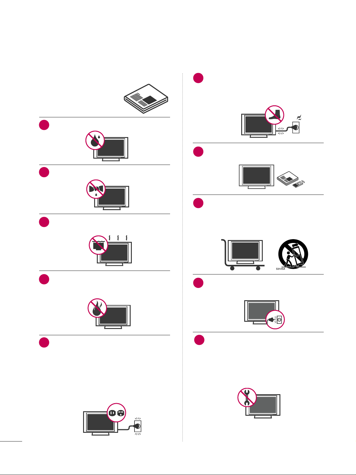
Do not use this apparatus near water.
Clean only with dry cloth.
Do not block any ventilation openings. Install in
accordance with the manufacturer’s instructions.
Do not install near any heat sources such as
radiators, heat registers, stoves, or other apparatus
(including amplifiers)that produce heat.
Do not defeat the safety purpose of the polarized
or grounding-type plug. A polarized plug has
two blades with one wider than the other. A
grounding type plug has two blades and a third
grounding prong, The wide blade or the third
prong are provided for your safety. If the provided
plug does not fit into your outlet, consult an
electrician for replacement of the obsolete outlet.
Protect the power cord from being walked on
or pinched particularly at plugs, convenience
receptacles, and the point where they exit from
the apparatus.
Only use attachments/accessories specified by
the manufacturer.
Use only with the cart, stand, tripod, bracket,
or table specified by the manufacturer, or sold
with the apparatus. When a cart is used, use
caution when moving the cart/apparatus
combination to avoid injury from tip-over.
Unplug this apparatus during lighting storms or
when unused for long periods of time.
Refer all servicing to qualified service personnel.
Servicing is required when the apparatus has been
damaged in any way, such as power-supply cord or
plug is damaged, liquid has been spilled or objects
have fallen into the apparatus, the apparatus has
been exposed to rain or moisture, does not operate
normally, or has been dropped.
2
IMPORTANT SAFETY INSTRUCTIONS
SAFETY INSTRUCTIONS
1
2
3
4
5
7
8
6
9
10
Page 5
3
Never touch this apparatus or antenna during a
thunder or lighting storm.
When mounting a TV on the wall, make sure not to
install the TV by the hanging power and signal
cables on the back of the TV.
Do not allow an impact shock or any objects to fall
into the product, and do not drop onto the screen
with something.
CAUTION concerning the Power Cord :
It is recommend that appliances be placed upon a
dedicated circuit; that is, a single outlet circuit which
powers only that appliance and has no additional
outlets or branch circuits. Check the specification
page of this owner's manual to be certain.
Do not connect too many appliances to the same
AC power outlet as this could result in fire or electric shock.
Do not overload wall outlets. Overloaded wall outlets, loose or damaged wall outlets, extension cords,
frayed power cords, or damaged or cracked wire
insulation are dangerous. Any of these conditions
could result in electric shock or fire. Periodically
examine the cord of your appliance, and if its
appearance indicates damage or deterioration,
unplug it, discontinue use of the appliance, and
have the cord replaced with an exact replacement
part by an authorized servicer. Protect the power
cord from physical or mechanical abuse, such as
being twisted, kinked, pinched, closed in a door, or
walked upon. Pay particular attention to plugs, wall
outlets, and the point where the cord exits the
appliance.
Do not make the TV with the power cord plugged
in. Do not use a damaged or loose power cord. Be
sure do grasp the plug when unplugging the power
cord. Do not pull on the power cord to unplug the
TV.
WARNING - To reduce the risk of fire or electrical
shock, do not expose this product to rain, moisture
or other liquids. Do not touch the TV with wet
hands. Do not install this product near flammable
objects such as gasoline or candles or expose the
TV to direct air conditioning.
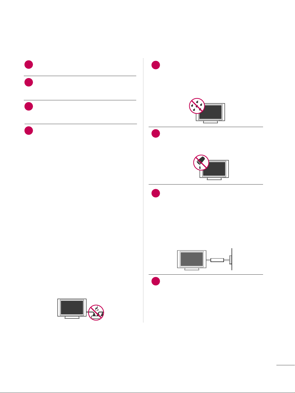
Do not expose to dripping or splashing and do not
place objects filled with liquids, such as vases, cups,
etc. on or over the apparatus (e.g. on shelves above
the unit).
GGRROOUUNNDDIINNGG
Ensure that you connect the earth ground wire to
prevent possible electric shock. (i.e. a TV with a
three-prong grounded AC plug must be connected
to a three-prong grouned AC outlet) If grounding
methods are not possible, have a qualified electrician install a separate circuit breaker.
Do not try to ground the unit by connecting it to
telephone wires, lightening rods, or gas pipes.
DDIISSCCOONNNNEECCTTIINNGG DDEEVVIICCEE FFRROOMM MMAAIINNSS
Mains plug is the disconnecting device. The plug
must remain readily operable.
12
11
14
13
16
17
18
Power
Supply
Short-circuit
Breaker
15
Page 6
4
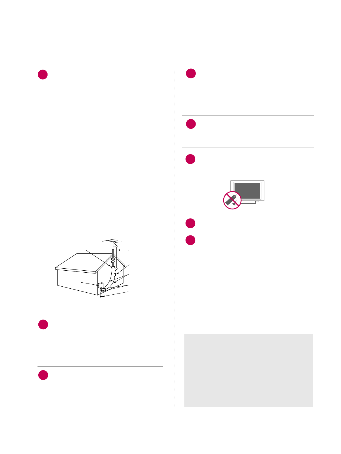
AANNTTEENNNNAASS
OOuuttddoooorr aanntteennnnaa ggrroouunnddiinngg
If an outdoor antenna is installed, follow the precautions below. An outdoor antenna system should not
be located in the vicinity of overhead power lines or
other electric light or power circuits, or where it can
come in contact with such power lines or circuits as
death or serious injury can occur.
Be sure the antenna system is grounded so as to provide some protection against voltage surges and
built-up static charges.
Section 810 of the National Electrical Code (NEC) in
the U.S.A. provides information with respect to proper grounding of the mast and supporting structure,
grounding of the lead-in wire to an antenna discharge unit, size of grounding conductors, location of
antenna discharge unit, connection to grounding
electrodes and requirements for the grounding electrode.
AAnntteennnnaa ggrroouunnddiinngg aaccccoorrddiinngg ttoo tthhee
NNaattiioonnaall EElleeccttrriiccaall CCooddee,, AANNSSII//NNFFPPAA 7700
Cleaning
When cleaning, unplug the power cord and scrub
gently with a soft cloth to prevent scratching. Do not
spray water or other liquids directly on the TV as
electric shock may occur. Do not clean with chemicals such as alcohol, thinners or benzene.
Moving
Make sure the product is turned off, unplugged
and all cables have been removed. It may take 2 or
more people to carry larger TVs. Do not press
against or put stress on the front panel of the TV.
Ventilation
Install your TV where there is proper ventilation. Do
not install in a confined space such as a bookcase.
Do not cover the product with cloth or other materials (e.g.) plastic while plugged in. Do not install in
excessively dusty places.
If you smell smoke or other odors coming from the
TV or hear strange sounds, unplug the power cord
contact an authorized service center.
Do not press strongly upon the panel with a hand or
sharp object such as nail, pencil or pen, or make a
scratch on it.
Keep the product away from direct sunlight.
FF oorr LL CCDD TT VV
If the TV feels cold to the touch, there may be
a small “flicker” when it is turned on. This is
normal, there is nothing wrong with TV.
Some minute dot defects may be visible on the
screen, appearing as tiny red, green, or blue
spots. However, they have no adverse effect on
the monitor's performance.
Avoid touching the LCD screen or holding your
finger(s) against it for long periods of time.
Doing so may produce some temporary distortion effects on the screen.
21
19
Antenna Lead in Wire
Antenna Discharge Unit
(NEC Section 810-20)
Grounding Conductors
(NEC Section 810-21)
Ground Clamps
Power Service Grounding
Electrode System (NEC
Art 250, Part H)
Ground Clamp
Electric Service
Equipment
NEC: National Electrical Code
22
23
24
25
20
ON DISPOSAL
(Only Hg lamp used LCD TV)
The fluorescent lamp used in this product contains
a small amount of mercury. Do not dispose of
this product with general household waste.
Disposal of this product must be carried out in
accordance to the regulations of your local authority.
26
Page 7

5
CONTENTS
WARNING / CAUTION
. . . . . . . . . . . . . . . . . . . . . . . . . . . . 1
SAFETY INSTRUCTIONS
. . . . . . . . . . . . . . . . . . . . . . . . . .
2
FEATURES OF THIS TV
. . . . . . . . . . . . . . . . . . . . . . . . . . . . . 7
PREPARATION
Accessories
. . . . . . . . . . . . . . . . . . . . . . . . . . . . . . . . . . . . . . . . . . . . . . . . . . . . . . 8
Front Panel Information
. . . . . . . . . . . . . . . . . . . . . . . . . . . . . . . . . . . . . 9
Back Panel Information
. . . . . . . . . . . . . . . . . . . . . . . . . . . . . . . . . . . . 10
Stand Instruction
. . . . . . . . . . . . . . . . . . . . . . . . . . . . . . . . . . . . . . . . . . . . . 12
Cable Management
. . . . . . . . . . . . . . . . . . . . . . . . . . . . . . . . . . . . . . . . .13
Desktop Pedestal Installation
. . . . . . . . . . . . . . . . . . . . . . . . . . . . 14
Swivel Stand
. . . . . . . . . . . . . . . . . . . . . . . . . . . . . . . . . . . . . . . . . . . . . . . . . . . . 14
Attaching the TV to a desk
. . . . . . . . . . . . . . . . . . . . . . . . . . . . . . . 15
VESA Wall Mounting
. . . . . . . . . . . . . . . . . . . . . . . . . . . . . . . . . . . . . . . . 16
Securing the TV to the wall to prevent falling
When the TV is used on a stand
. . . . . . . . . . . . . . . . . . . . . . . . . . 17
Antenna or Cable Connection
. . . . . . . . . . . . . . . . . . . . . . . . . . 18
MPI Card Slot / PPV Card Installation
. . . . . . . . . . . . . . . 19
EXTERNAL EQUIPMENT SETUP
HD Receiver Setup
- Component Connection
. . . . . . . . . . . . . . . . . . . . . . . . . . .20
- HDMI Connection
. . . . . . . . . . . . . . . . . . . . . . . . . . . . . . . . . . . . . 21
- DVI to HDMI Connection
. . . . . . . . . . . . . . . . . . . . . . . . . . 22
DVD Setup
- Component Connection
. . . . . . . . . . . . . . . . . . . . . . . . . . . . 23
- HDMI Connection
. . . . . . . . . . . . . . . . . . . . . . . . . . . . . . . . . . . . 24
VCR Setup
- Antenna Connection
. . . . . . . . . . . . . . . . . . . . . . . . . . . . . . . . . 25
- Composite (RCA) Connection
. . . . . . . . . . . . . . . . . . . 25
Other A/V Source Setup
. . . . . . . . . . . . . . . . . . . . . . . . . . . . . . . . . 26
PC Setup
- VGA (D-Sub 15 pin) Connection
. . . . . . . . . . . . . . . 27
- DVI to HDMI Connection
. . . . . . . . . . . . . . . . . . . . . . . . . . 28
- Screen Setup for PC mode
. . . . . . . . . . . . . . . . . . . . . . . . 29
Audio Out Connection
. . . . . . . . . . . . . . . . . . . . . . . . . . . . . . . . . . . . 33
WATCHING TV / CHANNEL CONTROL
Remote Control Functions . . . . . . . . . . . . . . . . . . . . . . . . . . . . . . . 34
Turning On TV
. . . . . . . . . . . . . . . . . . . . . . . . . . . . . . . . . . . . . . . . . . . . . . . . 36
Channel Selection
. . . . . . . . . . . . . . . . . . . . . . . . . . . . . . . . . . . . . . . . . . . 36
Volume Adjustment
. . . . . . . . . . . . . . . . . . . . . . . . . . . . . . . . . . . . . . . . .36
On-Screen Menus Selection
. . . . . . . . . . . . . . . . . . . . . . . . . . . . . 37
Channel Setup
- Auto Scan (Auto Tuning)
. . . . . . . . . . . . . . . . . . . . . . . . . . .38
- Add / Delete Channel (Manual Tuning)
. . . . . . 39
- Channel Editing
. . . . . . . . . . . . . . . . . . . . . . . . . . . . . . . . . . . . . . . . 40
Channel Label
. . . . . . . . . . . . . . . . . . . . . . . . . . . . . . . . . . . . . . . . . . . . . . . . .41
Input List
. . . . . . . . . . . . . . . . . . . . . . . . . . . . . . . . . . . . . . . . . . . . . . . . . . . . . . . .42
Example Electronic Program Guide
. . . . . . . . . . . . . . . . . . . 43
PICTURE CONTROL
PIP (Picture-In-Picture)
. . . . . . . . . . . . . . . . . . . . . . . . . . . . . . . . . . . . 44
Picture Size (Aspect Ratio) Control
. . . . . . . . . . . . . . . . . . 46
Preset Picture Settings
- Picture Mode - Preset
. . . . . . . . . . . . . . . . . . . . . . . . . . . . . . . 49
- Color Tone - Preset
. . . . . . . . . . . . . . . . . . . . . . . . . . . . . . . . . .50
Manual Picture Adjustment
- Picture Mode - User Mode
. . . . . . . . . . . . . . . . . . . . . . . . 51
Picture Improvement Technology
. . . . . . . . . . . . . . . . . . . . . 52
Advanced Control - Black (Darkness) Level
. . . . . . . 53
Advanced Control - Eye Care
. . . . . . . . . . . . . . . . . . . . . . . . . . .54
Advanced Control -
Film Mode . . . . . . . . . . . . . . . . . . . . . . . . .55
Picture Reset
. . . . . . . . . . . . . . . . . . . . . . . . . . . . . . . . . . . . . . . . . . . . . . . . .56
SOUND & LANGUAGE CONTROL
Auto Volume Leveler (Auto Volume)
. . . . . . . . . . . . . . . . . 57
Preset Sound Settings (Sound Mode)
. . . . . . . . . . . . . . 58
Sound Setting Adjustment - User Mode
. . . . . . . . . . . 59
- SRS TruSurround XT
. . . . . . . . . . . . . . . . . . . . . . . . . . . . . . . . . 60
Clear Voice
. . . . . . . . . . . . . . . . . . . . . . . . . . . . . . . . . . . . . . . . . . . . . . . . . . . . . 61
Balance
. . . . . . . . . . . . . . . . . . . . . . . . . . . . . . . . . . . . . . . . . . . . . . . . . . . . . . . . . . 62
TV Speakers On/Off Setup
. . . . . . . . . . . . . . . . . . . . . . . . . . . . . . 63
Audio Reset
. . . . . . . . . . . . . . . . . . . . . . . . . . . . . . . . . . . . . . . . . . . . . . . . . . . 64
Stereo/SAP Broadcast Setup
. . . . . . . . . . . . . . . . . . . . . . . . . . .65
Audio Language
. . . . . . . . . . . . . . . . . . . . . . . . . . . . . . . . . . . . . . . . . . . . . . 66
On-Screen Menus Language Selection
. . . . . . . . . . . . . . 67
Caption Mode
- Analog Broadcasting System Captions
. . . . . . . 68
- Digital Broadcasting System Captions
. . . . . . . . 69
- Caption Option
. . . . . . . . . . . . . . . . . . . . . . . . . . . . . . . . . . . . . . . 70
TIME SETTING
Clock Setting
- Auto Clock Setup
. . . . . . . . . . . . . . . . . . . . . . . . . . . . . . . . . . . . 71
- Manual Clock Setup
. . . . . . . . . . . . . . . . . . . . . . . . . . . . . . . . . 72
Auto On/Off Time Setting
. . . . . . . . . . . . . . . . . . . . . . . . . . . . . . 73
Sleep Timer Setting
. . . . . . . . . . . . . . . . . . . . . . . . . . . . . . . . . . . . . . . . .74
Auto Shut-off Setting
. . . . . . . . . . . . . . . . . . . . . . . . . . . . . . . . . . . . . . . 75
Page 8

6
PARENTAL CONTROL / RATINGS
Set Password & Lock System . . . . . . . . . . . . . . . . . . . . . . . . . . . 76
Channel Blocking
. . . . . . . . . . . . . . . . . . . . . . . . . . . . . . . . . . . . . . . . . . . . 79
Movie & TV Rating
. . . . . . . . . . . . . . . . . . . . . . . . . . . . . . . . . . . . . . . . .80
Downloadable Rating
. . . . . . . . . . . . . . . . . . . . . . . . . . . . . . . . . . . . . . 83
External Input Blocking
. . . . . . . . . . . . . . . . . . . . . . . . . . . . . . . . . . . . 84
COMMERCIAL MODE SETUP
Interactive TV Setup
. . . . . . . . . . . . . . . . . . . . . . . . . . . . . . . . . . . . . . . . 85
Installer Overview
. . . . . . . . . . . . . . . . . . . . . . . . . . . . . . . . . . . . . . . . . . . . 86
Interactive TV Overview
. . . . . . . . . . . . . . . . . . . . . . . . . . . . . . . . . . . 87
Commercial Mode Setup for Master TV
. . . . . . . . . . . . 88
Master TV Profile Setup Learning/Teaching with
USB Memory Card
. . . . . . . . . . . . . . . . . . . . . . . . . . . . . . . . . . . . . . . . . . 89
TLL-1100A Cloning Connections/Learning Setup
. . . . . . . . . . . . . . . . . . . . . . . . . . . . . . . . . . . . . . . . . . . . . . . . . . . . . . . . . . . . . . . . . . . . . .
91
LT2002 Cloning Connections/Learning Setup
. . 92
LT2002 Cloning Learning Setup
. . . . . . . . . . . . . . . . . . . . . . 93
Cloning Connections/Teaching Setup
. . . . . . . . . . . . . . 94
Installer Menu
. . . . . . . . . . . . . . . . . . . . . . . . . . . . . . . . . . . . . . . . . . . . . . . . .
95
Reference: Detailed Instructions For Making A
Master TV
. . . . . . . . . . . . . . . . . . . . . . . . . . . . . . . . . . . . . . . . . . . . . . . . . . . . .
101
Reference: Procedures for adding Channel Label
Icons/Custom Channel Labels (2-5-4 + MENU
Mode)
. . . . . . . . . . . . . . . . . . . . . . . . . . . . . . . . . . . . . . . . . . . . . . . . . . . . . . . . . . 10 2
Reference: Clonable Menu Features
. . . . . . . . . . . . . . . . 10 3
Reference: Power Saving Setup
. . . . . . . . . . . . . . . . . . . . . . . 10 4
TV Aux Input Configuration
. . . . . . . . . . . . . . . . . . . . . . . . . . .10 4
TV Camport Auto Sense Operation
. . . . . . . . . . . . . . . . 10 5
APPENDIX
Troubleshooting . . . . . . . . . . . . . . . . . . . . . . . . . . . . . . . . . . . . . . . . . . . . 10 6
Reference: LT2002 Cloning Procedure
Troubleshooting
. . . . . . . . . . . . . . . . . . . . . . . . . . . . . . . . . . . . . . . . . . . . 10 8
Troubleshooting Flow Chart
. . . . . . . . . . . . . . . . . . . . . . . . . . .10 9
Commercial Mode Check
. . . . . . . . . . . . . . . . . . . . . . . . . . . . . . . . 110
Glossary of Terms
. . . . . . . . . . . . . . . . . . . . . . . . . . . . . . . . . . . . . . . . . . . 111
Maintenance
. . . . . . . . . . . . . . . . . . . . . . . . . . . . . . . . . . . . . . . . . . . . . . . . . . 112
Product Specifications
. . . . . . . . . . . . . . . . . . . . . . . . . . . . . . . . . . . . 112
Programming the Remote Control
. . . . . . . . . . . . . . . . . . . 113
IR Codes
. . . . . . . . . . . . . . . . . . . . . . . . . . . . . . . . . . . . . . . . . . . . . . . . . . . . . . . 116
Open Source License
. . . . . . . . . . . . . . . . . . . . . . . . . . . . . . . . . . . . . . 118
Page 9
7
FEATURES OF THIS TV
is a trademark of SRS Labs, Inc.
TruSurround XT technology is incorporated under
license from SRS Labs, Inc.
Manufactured under license from Dolby Laboratories.
“
Dolby
“and the double-D symbol are trademarks of
Dolby Laboratories.
USB IN
SERVUCE ONLYSERVUCE ONLY
USB port shall be used for software update by service
personnel only.
HDMITM, the HDMI logo and High-Definition
Multimedia Interface are trademarks or registered
trademarks of HDMI Licensing."
■
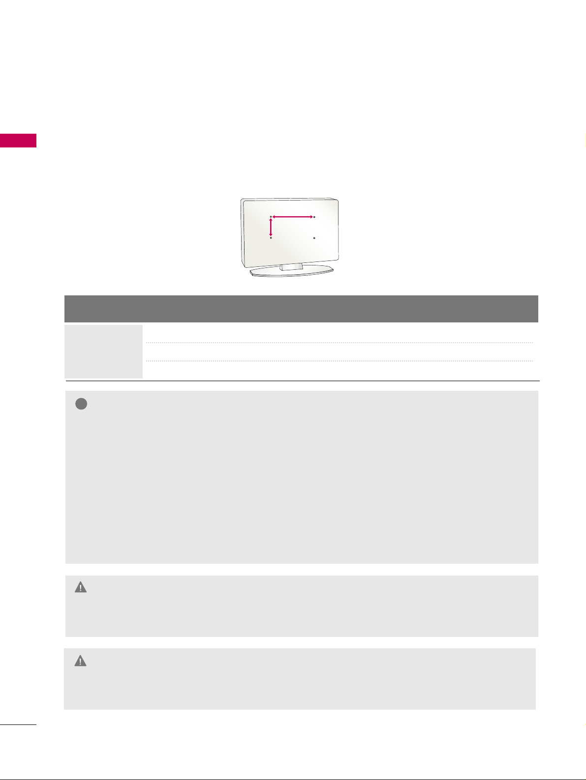
When a fixed image (e.g. logos, screen menus, video game, and computer display) is displayed on the TV
for an extended period, it can become permanently imprinted on the screen. This phenomenon is known
as “image burn” or “burn-in.” Image burn is not covered under the manufacturer’s warranty.
■
In order to prevent image burn, avoid displaying a fixed image on your TV screen for a prolonged period
(2 or more hours for LCD, 1 or more hours for Plasma).
■
Image burn can also occur on the letterboxed
areas of your TV if you use the 4:3 aspect
ratio setting for an extended period.
IMPORTANT INFORMATION TO PREVENT “IMAGE BURN
/ BURN-IN” ON YOUR TV SCREEN
Page 10
8
PREPERATION
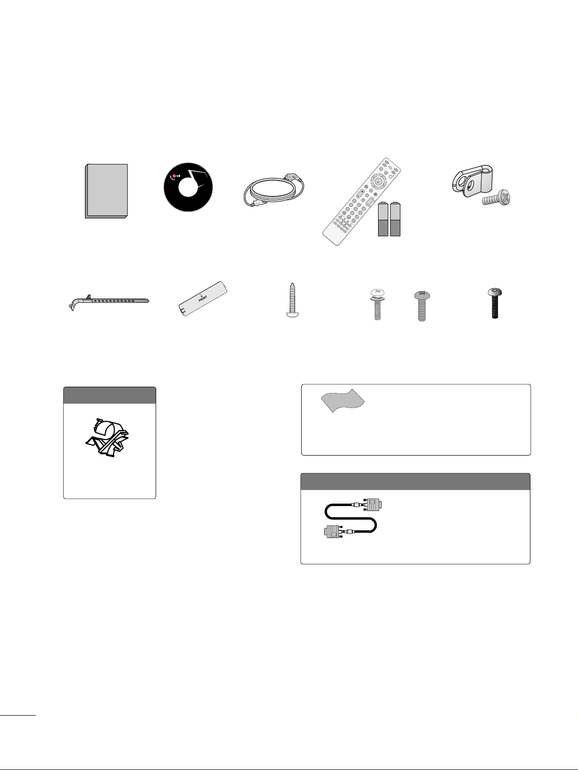
ACCESSORIES
Ensure that the following accessories are included with your TV. If an accessory is missing, please contact the
dealer where you purchased the TV.
The accessories included may differ from the images below.
Copyright© 2007 LGE,
All Rights Reserved.
Owner’s Manual
Power Cord
CD Manual
Protective Bracket and
Bolt for Power Cord
(Refer to P.13)
Cable Holder
(Refer to P.13)
* Wipe spots on the exterior only with the pol-
ishing cloth.
* Do not wipe roughly when removing stains.
Excessive pressure may cause scratches or
discoloration.
Polishing Cloth
(This feature is not avail-
able for all models.)
3322LLGG770000HH oonnllyy
OOppttiioonn EExxttrraass
D-sub 15 pin Cable
When using the VGA (D-sub 15 pin
cable) PC connection, the user
must use shielded signal interface
cables with ferrite cores to maintain
standards compliance.
x 2
Torx plus
Star head screw
(Refer to P.12)
Screw for stand fixing
(Refer to P.15)
Bolts for stand assembly
(Refer to P.12)
x 4 x 4
1.5V 1.5V
Remote Control,
Batteries
M
U
TE
RETURN
C
C
TV
P
O
W
ER
GUIDE
PORTAL
ENT
E
R
VOL
CH
123
456
78
0
9
FLASHB
K
VCR
DVD
INPU
T
M
E
NU
INFO
i
STB
P
A
G
E
PIP
SAP
PIP CH-
PIP CH+
PIP SWAP
PIP INPU
T
ALPHA/NU
M
RE
M
OVE
RATIO
TIM
E
R
ABC
DEF
GHI
WX
Y
Z
T
U
V
PQRS
MNO
JKL
&
@
.:/,
Protection Cover
(Refer to P.12)
Cable Holder
(Refer to P.13)
Page 11
PREPARATION
9
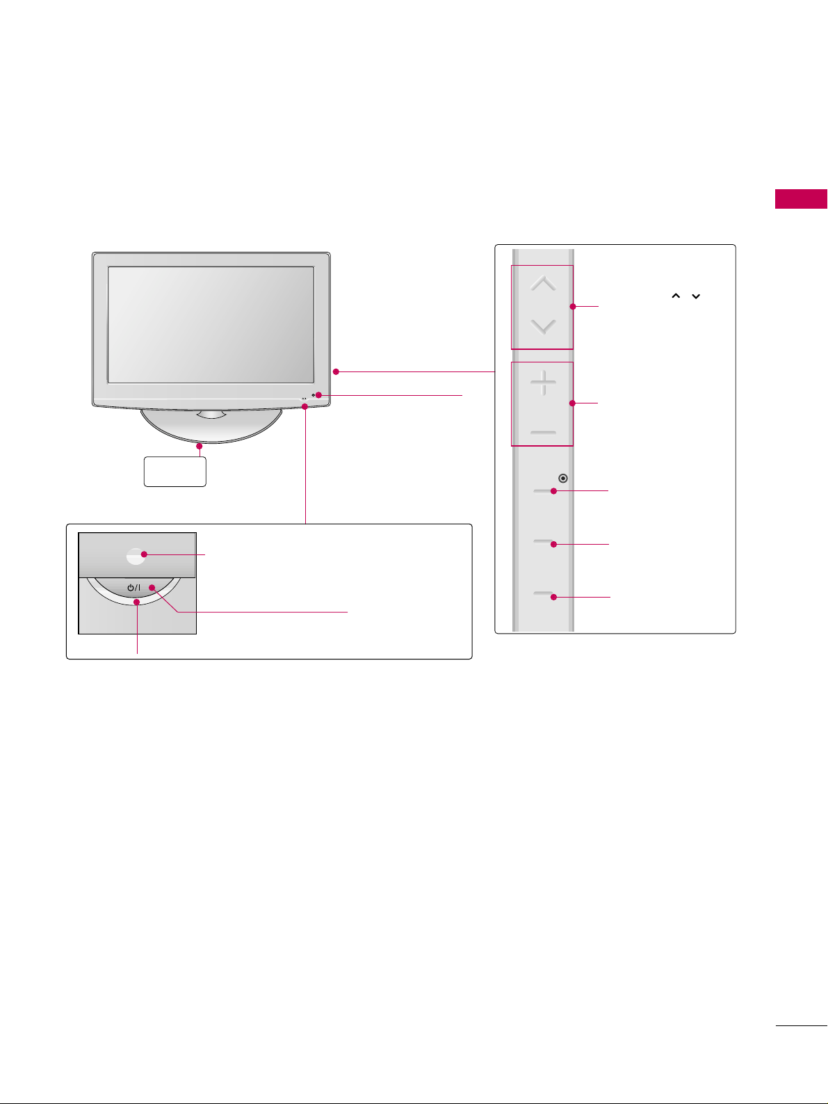
FRONT PANEL INFORMATION
■
Image shown may differ from your TV.
POWER Button
Power/Standby Indicator
Illuminates red in standby mode.
Illuminates blue when the set is switched on.
VOLUME (+, -)
Buttons
ENTER Button
MENU Button
INPUT Button
Remote Control Sensor
CHANNEL( , )
Buttons
Stand
Intelligent Sensor
CH
VOL
ENTER
MENU
INPUT
Page 12
PREPARATION
10
PREPARATION
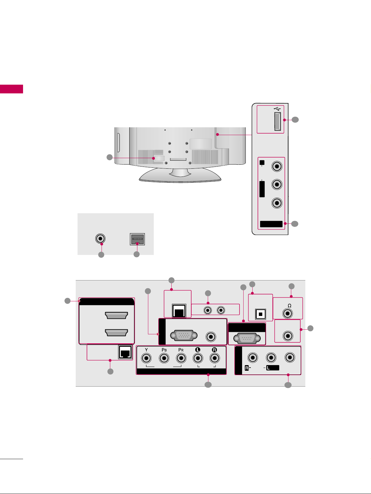
■
Image shown may differ from your TV.
BACK PANEL INFORMATION
R
8
2
4
R
ANTENNA IN
M.P.I.
7
1
3
5
6
9
10
11
12
13
15
14
11
USB
SERVICE ONLY
ANTENNA IN
HDMI/DVI IN
2
1(DVI)
M.P.I.
LAN
(SERVICE ONLY)
RGB(PC)
RESET
AUDIO
(RGB/DVI)
UPDATE
RS-232C IN
(SERVICE ONLY)
R
AUDIO
L/ MONO
VIDEO
AV I N 2
OPTICAL
DIGITAL
AUDIO OUT
SPEAKER OUT
8
REMOTE
CONTROL OUT
RGB IN
RJP
INTERFACE
VIDEO
COMPONENT IN
AUDIO
AV IN 1
AUDIO
MONO
/
VIDEO
Page 13

PREPARATION
11
REMOTE CONTROL OUT
IR output for controlling an auxiliary device.
RJP INTERFACE (REMOTE JACK PACK PORT)
Connect to remote jack pack control output port.
COMPONENT IN
Analog Connection.
Supports HD.
Uses a red, green, and blue cable for video & a red
and white cable for audio.
AV (Audio/Video) IN
Analog composite connection. Supports standard
definition video only (480i).
Used for PC/DTV audio input jack.
USB SERVICE ONLY
Used for software updates.
ANTENNA IN
Connect over-the air signals to this jack.
M.P. I.
Power Cord Socket
For operation with AC power.
Caution: Never attempt to operate the TV on DC
power.
HDMI/DVI IN
Digital Connection. Supports HD video and Digital
audio.
Accepts DVI video using an adapter or HDMI to
DVI cable (not included)
LAN (SERVICE ONLY)
Connect to control network.
UPDATE
Software downloads and debug mode enable/disable.
RESET
Hardware reset to PTC microcontroller.
OPTICAL DIGITAL AUDIO OUT
Digital audio output for use with amps and home
theater systems.
Includes an optical connection.
Note: In standby mode, these ports do not work.
SPEAKER OUT 8
Ω
Connect to external speaker input.
RGB IN (PC)
Analog PC Connection. Uses a D-sub 15 pin cable
(VGA cable).
AUDIO (RGB/DVI)
1/8” headphone jack for analog PC audio input.
RS-232C IN (SERVICE ONLY)
Used for software updates.
1
2
3
4
5
9
8
6
7
10
11
12
13
14
15
Page 14
PREPARATION
12
STAND INSTRUCTION
PREPARATION
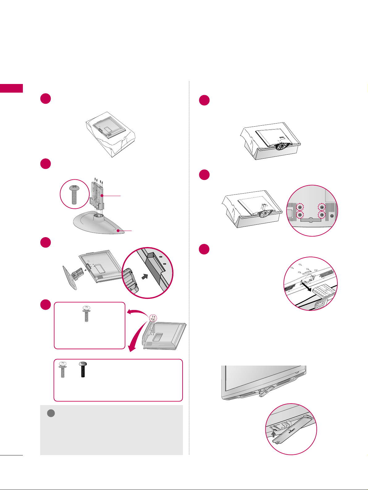
Carefully place the TV screen side down on a
cushioned surface to protect the screen from
damage.
Assemble the parts of the
SSTTAANNDD BBOODDYY
with
CCOO VVEERR BBAASS EE
of the TV.
1
2
Insert the stand as shown.
3
SSTTAANNDD BB OODDYY
CCOO VVEERR BBAASS EE
■
Image shown may differ from your TV.
GG
Make sure the screws in the stand are fully
tightened. (If not tightened fully, the product
could tilt forward and fall). But do not over
tighten, over-tightening can damage the threads
on the screws.
NOTE
!
DETACHMENT
Carefully place the TV screen side down on a
cushioned surface to protect the screen from
damage.
1
Remove the four screws that hold the base on.
2
Detach the stand from TV.
3
INSTALLATION
4
or
x 4
Tighten the stand with the
four screws (provided as parts
of the TV).
Tighten the two of these four screws
and the two Torx plus star head screws
(provided as parts of the TV) to secure the TV. Tighten
the two Torx plus star head screws with a star head driver bit (not provided as parts of the TV).
x 2
x 2
After removing the stand, install the included
pp rr oottee cc ttiioonn cc oovveerr
over the hole for the stand.
Press the
PPRROOTTEECCTTIIOONN CC OOVV EE RR
into the TV
until you hear it click.
PROTECTION COVER
Page 15
PREPARATION
13
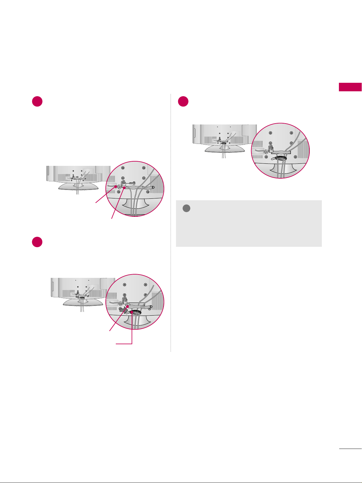
CABLE MANAGEMENT
■
Image shown may differ from your TV.
Connect the cables as necessary.
To connect additional equipment, see the
EXTERNAL EQUIPMENT SETUP section.
Secure the power cable with the CABLE
HOLDER for power code(only 32LG700H
model) and PROTECTIVE BRACKET/Screw.
It will help prevent the power cable from
being removed by accident.
Install the CABLE MANAGEMENT CLIP as
shown.
If your TV has the CABLE HOLDER, install it
as shown and bundle the cables.
1
2
Put the cables inside the CABLE MANAGEMENT
CLIP and snap it closed.
3
PROTECTIVE BRACKET
(This feature is not available
for all models.)
GG
Do not hold the CABLE MANAGEMENT CLIP
when moving the TV.
- If the TV is dropped, you may be injured or the
product may be broken.
NOTE
!
CABLE MANAGEMENT CLIP
CABLE HOLDER
CABLE HOLDER
(only 32LG700H model)
Page 16
PREPARATION
14
PREPARATION
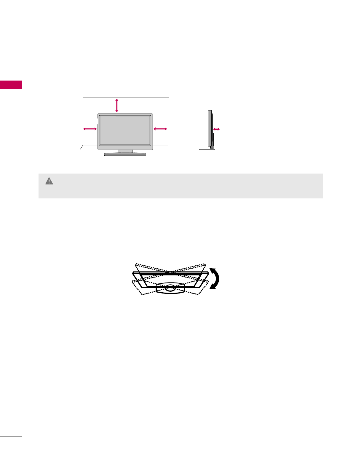
DESKTOP PEDESTAL INSTALLATION
For proper ventilation, allow a clearance of 4 inches on all four sides.
■
Image shown may differ from your TV.
4 inches
4 inches
4 inches
4 inches
SWIVEL STAND
The TV can be conveniently swivelled on its stand 90° to the left or right to provide the optimum viewing angle.
GG
Ensure adequate ventilation by following the clearance recommendations.
GG
Do not mount near or above any type of heat source.
CAUTION
Page 17
PREPARATION
15
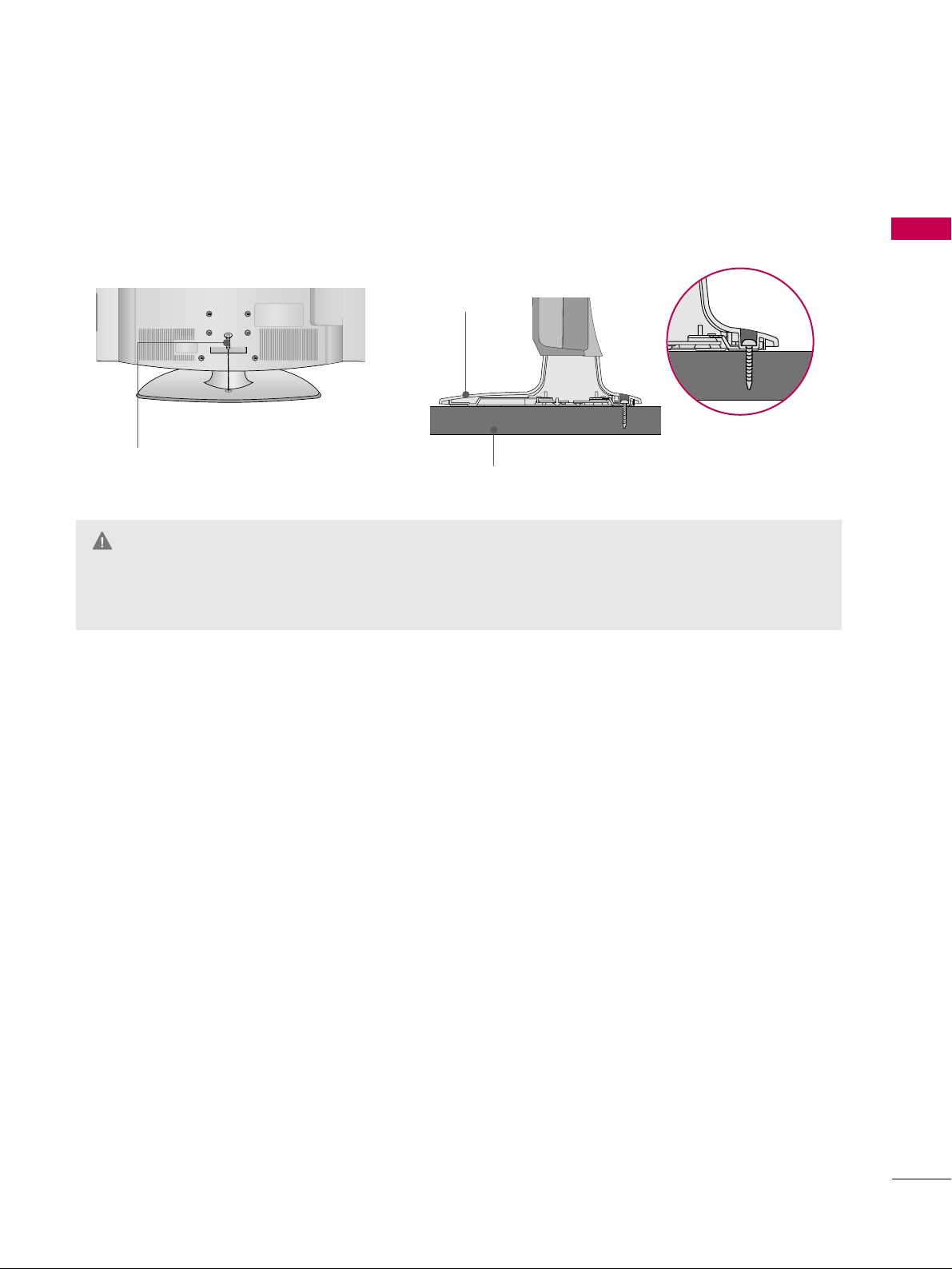
ATTACHING THE TV TO A DESK
The TV must be attached to a desk so it cannot be pulled in a forward/backward direction, potentially causing
injury or damaging the product. Use only the included screw.
GG
To prevent TV from falling over, the TV should be securely attached to the floor/wall per installation
instructions. Tipping, shaking, or rocking the TV may cause injury.
WARNING
1-Screw
(provided as parts of the product)
Desk
Stand
Page 18
PREPARATION
16
PREPARATION
VESA WALL MOUNTING
Install your wall mount on a solid wall perpendicular to the floor. When attaching to other building materials, please contact your nearest dealer.
If installed on a ceiling or slanted wall, it may fall and result in severe personal injury.
We recommend that you use an LG brand wall mount when mounting the TV to a wall.
GG
Do not install your wall mount kit while the TV is plugged in. It may result in personal injury due to electric
shock.
CAUTION
GG
Screw length needed depends on the wall mount
used. For further information, refer to the instructions included with the mount.
GG
Standard dimensions for wall mount kits are shown
in the table.
GG
When purchasing our wall mount kit, a detailed
installation manual and all parts necessary for
assembly are provided.
GG
Do not use screws longer then the standard dimension, as they may cause damage to the inside to
the TV.
GG
For wall mounts that do not comply with the VESA
standard screw specifications, the length of the
screws may differ depending on their specifications.
GG
Do not use screws that do not comply with the
VESA standard screw specifications.
Do not tighten the screws too much. It may damage the TV or allow the TV to a fall and cause personal injury. LG is not liable for these kinds of accidents.
GG
LG is not liable for TV damage or personal injury
when a non-VESA or non specified wall mount is
used or the consumer fails to follow the TV installation instructions.
NOTE
!
AA
BB
GG
To prevent injury, this apparatus must be securely attached to the wall in accordance with the installation instructions.
WARNING
Product Model
VESA
(A *B)
Standard Screw Quantity
32LG700H
37LG700H
42LG700H
200 * 100
M4
4
LCD TV
200 * 200
200 * 200
M6
M6
4
4
Page 19
PREPARATION
17
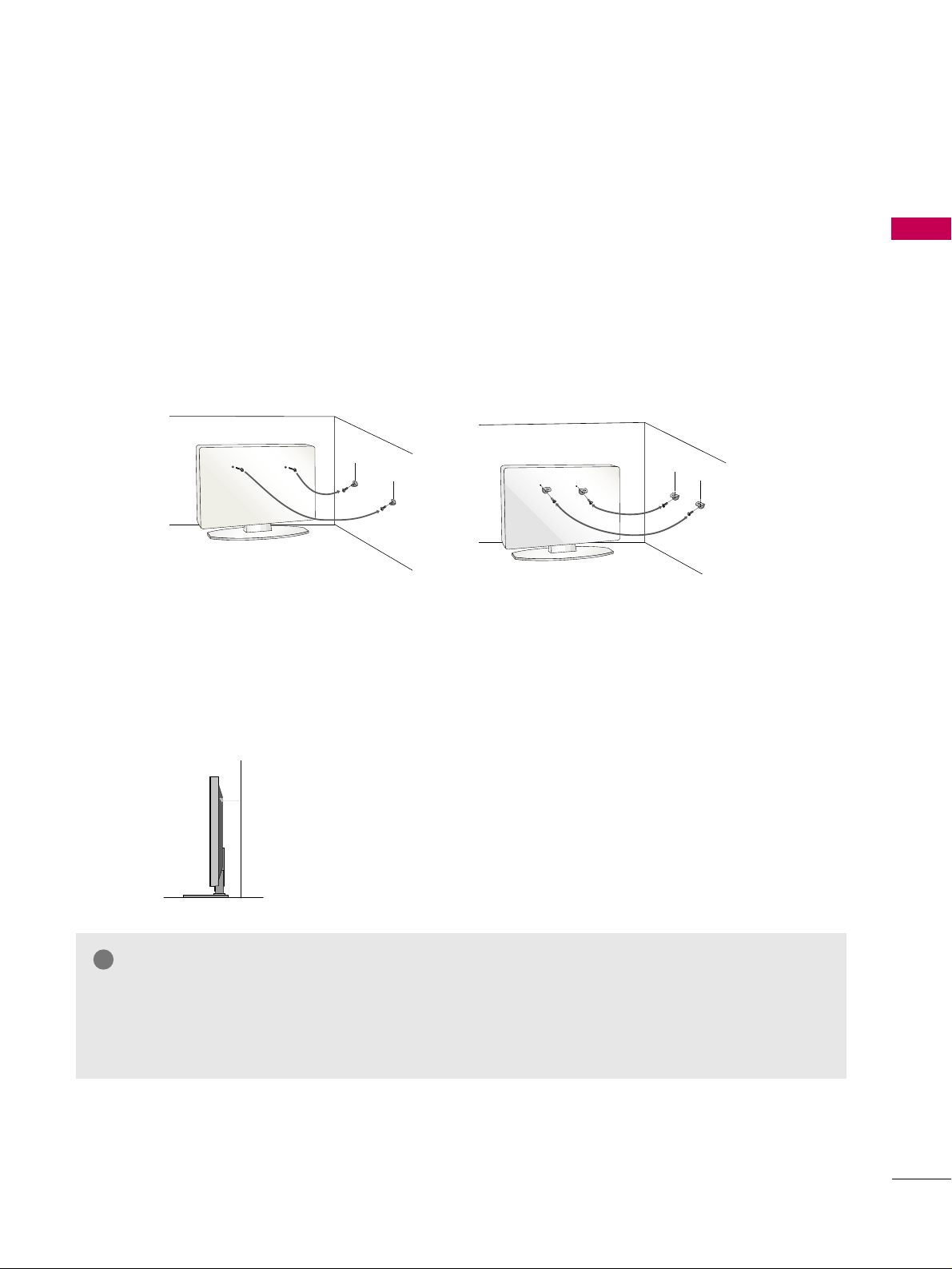
SECURING THE TV TO THE WALL TO PREVENT FALLING WHEN THE TV IS USED ON A STAND
We recommend that you set the TV close to a wall so it cannot fall over if pushed backwards.
Additionally, we recommend that the TV be attached to a wall so it cannot be pulled in a forward direction,
potentially causing injury or damaging the product.
Caution: Please make sure that children don’t climb on or hang from the TV.
■
Insert eye-bolts (or TV brackets and bolts) to attach the product to the wall as shown in the picture.
*If your product has the bolts in the eye-bolts position before inserting the eye-bolts, loosen the bolts.
* Insert the eye-bolts or TV brackets/bolts and tighten them securely in the upper holes.
Secure the wall brackets with screws (sold separately) to the wall. Match the height of the bracket that
is mounted on the wall to the holes in the product.
Ensure the eye-bolts or brackets are tightened securely.
■
Use a sturdy rope or cord (sold separately) to tie the product. It is
safer to tie the rope so it becomes horizontal between the wall and
the product (the less slack in the rope, the better).
■
You should purchase necessary components to prevent TV from falling off of the stand.
■
Image shown may differ from your TV.
* This feature is not available for all models.
GG
Use a platform or cabinet strong enough and large enough to support the size and weight of the TV.
GG
To use the TV safely, make sure that the height of the bracket on the wall and the one on the TV are
the same.
NOTE
!
Page 20
R
ANTENNA INANTENNA IN
M.P.I.
PREPARATION
18
PREPARATION
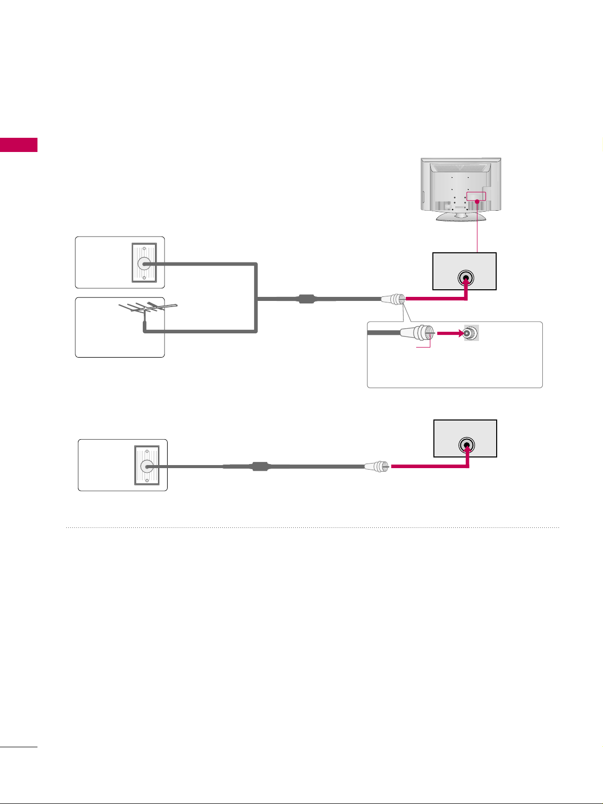
ANTENNA OR CABLE CONNECTION
1. Antenna (Analog or Digital)
Wall Antenna Socket or Outdoor Antenna without a Cable Box
Connection.
For optimum picture quality, adjust the direction if needed.
2. Cable
Wall
Antenna
Socket
Outdoor
Antenna
(VHF, UHF)
Cable TV
Wall Jack
Multi-family Dwellings/Apartments
(Connect to wall antenna socket)
RF Coaxial Wire (75 ohm)
RF Coaxial Wire (75 ohm)
Single-family Dwellings /Houses
(Connect to wall jack for outdoor antenna)
Be careful not to bend the copper wire
when connecting the antenna.
Copper Wire
■
To improve the picture quality in a poor signal area, please purchase a signal amplifier and install properly.
■
If the antenna needs to be split for two TV’s, install a 2-Way Signal Splitter.
■
If the antenna is not installed properly, contact your dealer for assistance.
R
■
To prevent damage do not connect to the power outlet until all connections are made between the devices.
R
ANTENNA INANTENNA IN
M.P.I.
Page 21
PREPARATION
19
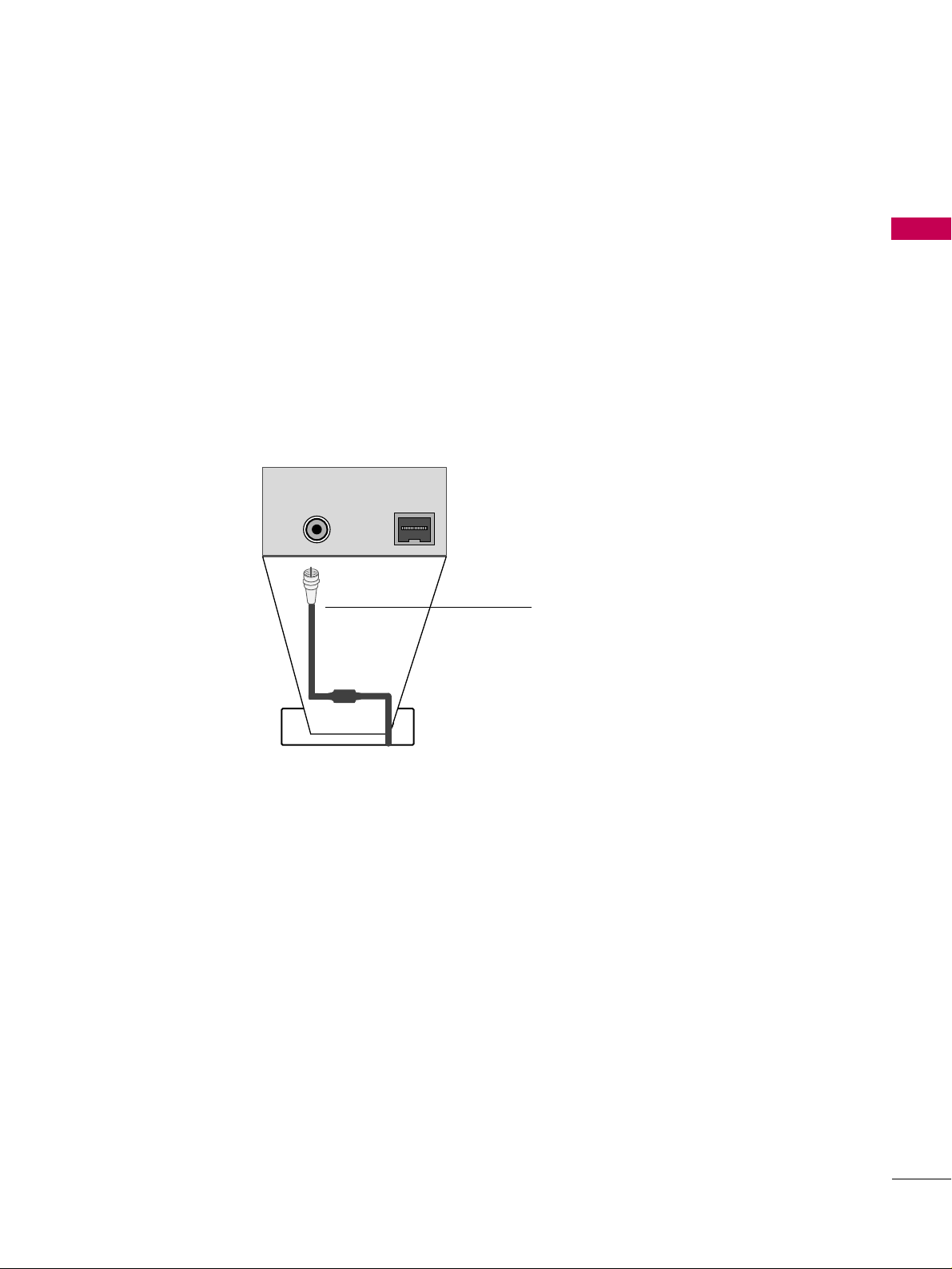
MPI CARD SLOT / PPV CARD INSTALLATION
1. Remove the two MPI card retainer screws.
2. Pull out current MPI card far enough so that the RF cable can be detached from the old card.
3. Detach RF cable.
4. Place new PPV card into slot and slide it in far enough to reconnect RF cable.
5. Insert card all the way into the slot making sure it is fully seated into back plane connector.
6. Replace the two card retainer screws.
The MPI card is equipped with an RF jack for antenna/cable signal source connection.
The MPI card slot is also available for installing a PPV (Pay-Per-View) card.
MPI Card Removal / PPV Card Installation
RF CABLE
RF cable needs to be
disconnected to remove
current card.
ANTENNA IN
M.PM.P.I.
M.P. I.
Card Slot
Page 22
PREPARATION
20
HD RECEIVER SETUP
EXTERNAL EQUIPMENT SETUP
This TV can receive Digital Over-the-air or Digital Cable signals without an external digital set-top box. However,
if you do receive digital signals from a digital set-top box or other digital external device, refer to the figure as
shown below.
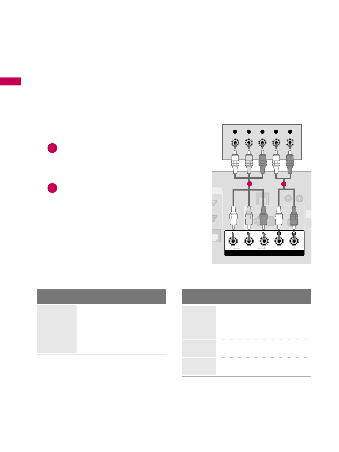
Component Connection
1. How to connect
Connect the video outputs (Y, P B, PR
)
of the digital set-
top box to the
CC OO MMPPOO NNEE NNTT IINN VV II DDEEOO
jacks on
the TV. Match the jack colors (Y = green, P
B = blue, and
P
R = red).
Connect the audio output of the digital set-top box to
the
CC OO MMPPOO NNEE NNTT IINN AAUUDDII OO
jacks on the TV.
2
1
2. How to use
■
Turn on the digital set-top box.
(
Refer to the owner’s manual for the digital set-top box.
)
■
Select
CC oommppoonnee nn tt
input source using the
IINNPPUUTT
button
on the remote control.
■
To prevent the equipment damage, never plug in any power cords until you have finished connecting all equipment.
■
Image shown may differ from your TV.
UPDA
RESET
LAN
(SERVICE ONLY)
RGB IN
RGB(PC)
AUDIO
(RGB/DVI)
COMPONENT IN
VIDEO
AUDIO
R
(S
Y L RP
B
P
R
1
2
Y, CB/PB, CR/PR
Supported Resolutions
Horizontal Vertical
Frequency(KHz)Frequency(Hz
)
15.73 59.94
15.73 60.00
31.47 59.94
31.47 60.00
44.96 59.94
45.00 60.00
33.72 59.94
33.75 60.00
Resolution
720x480i
720x480p
1280x720p
1920x1080i
Signal
480i
480p
720p
10 8 0 i
10 8 0 p
Component
Yes
Yes
Yes
Yes
No
HDMI
No
Yes
Yes
Yes
No
Page 23
EXTERNAL EQUIPMENT SETUP
21
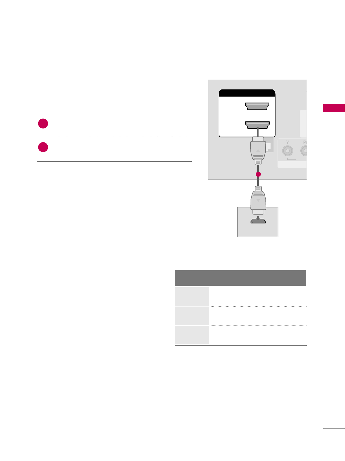
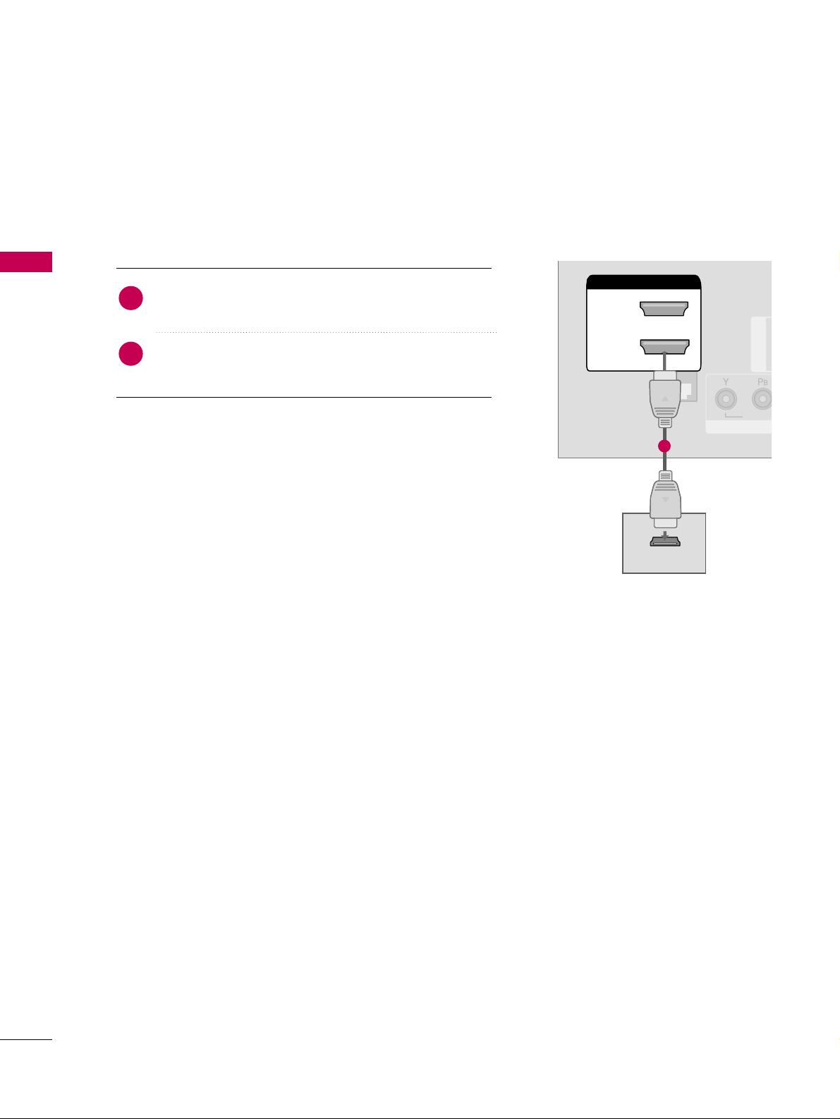
HDMI Connection
Connect the digital set-top box to
HHDDMMII// DD VV II II NN 11
((DD VVII)) or22
jack on the TV.
No separate audio connection is necessary.
HDMI supports both audio and video.
1. How to connect
2. How to use
■
Turn on the digital set-top box.
(
Refer to the owner’s manual for the digital set-top box.
)
■
Select
HHDDMMII 11
or
HHDDMMII 22
input source with using the
IINNPPUUTT
button on the remote control.
2
1
HDMI-DTV
RESET
UPDATE
(
RGB IN
CO
VID
HDMI/DVI IN
2
1(DVI)
RJP
INTERFACE
HDMI-DTV OUTPUT
1
Horizontal Vertical
Frequency(KHz)Frequency(Hz
)
31.47 59.94
31.47 60.00
44.96 59.94
45.00 60.00
33.72 59.94
33.75 60.00
Resolution
720x480p
1280x720p
1920x1080i
Page 24
EXTERNAL EQUIPMENT SETUP
22
EXTERNAL EQUIPMENT SETUP
DVI to HDMI Connection
RESET
LAN
(SERVICE ONLY)
RGB IN
RGB(PC)
COMPONENT IN
VIDEO
RJP
INTERFACE
AUDIO
AUDIO
(RGB/DVI)
HDMI/DVI IN
2
1(DVI)
LR
DVI-DTV OUTPUT
L
R
1
2
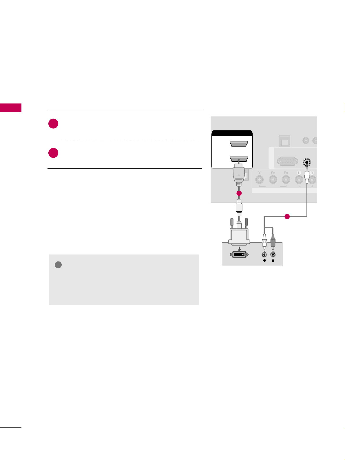
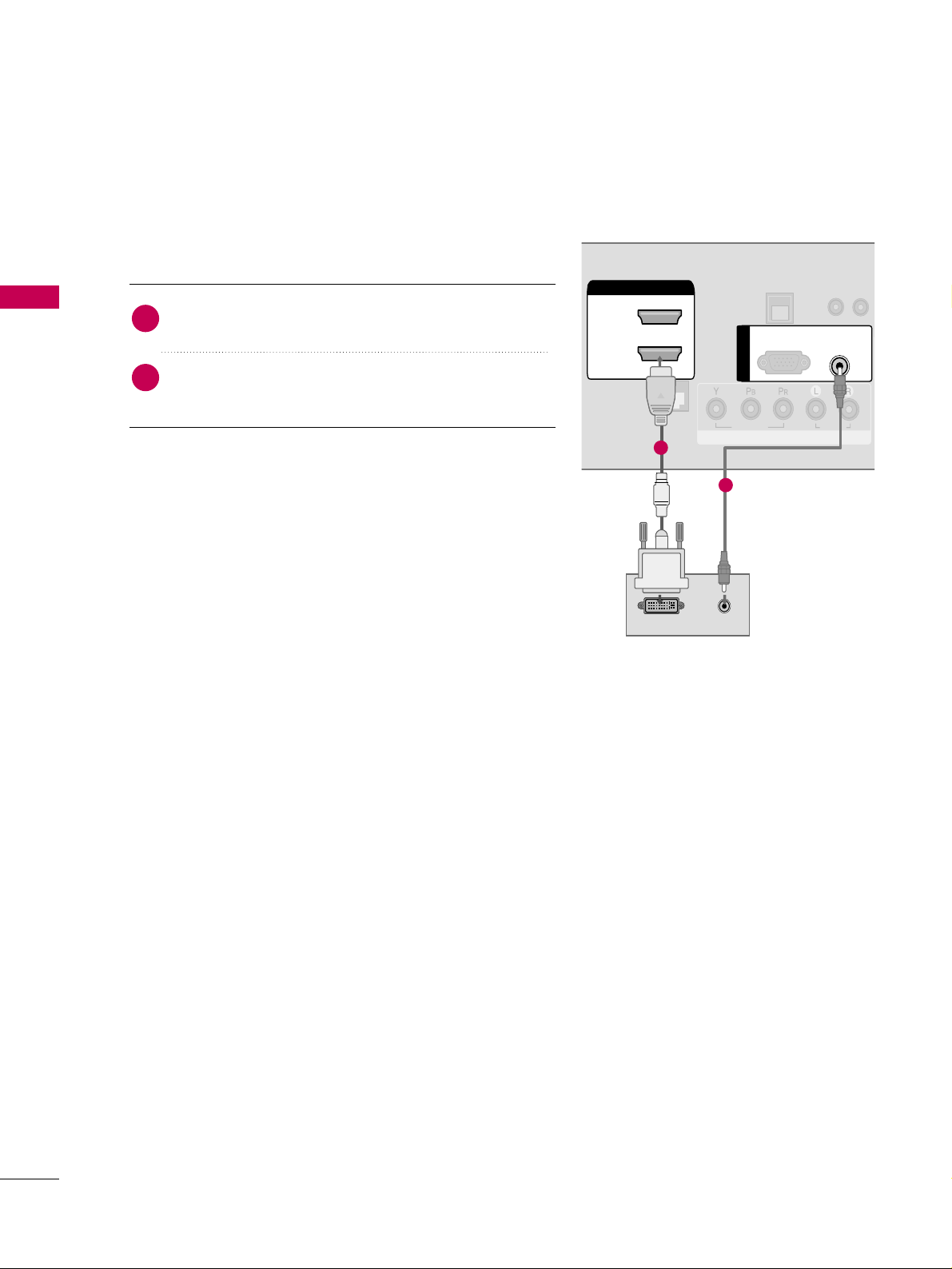
GG
A DVI to HDMI cable or adapter is required for this
connection. DVI doesn't support audio, so a separate
audio connection is necessary.
NOTE
!
Connect the DVI output of the digital set-top box to
the
HHDDMMII// DD VV II IINN 11 ((DDVVII))
jack on the TV.
Connect the audio output of the digital set-top box to
the
AAUUDDIIOO (( RRGGBB//DDVVII ))
jack on the TV.
1. How to connect
2. How to use
■
Turn on the digital set-top box. (Refer to the owner’s manual for the digital set-top box.
)
■
Select the
HHDDMMII 11
input source on the TV using the
IINNPP UUTT
button on the remote control.
2
1
Page 25
EXTERNAL EQUIPMENT SETUP
23
DVD SETUP
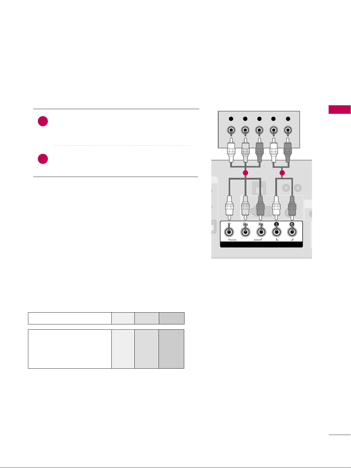
Component Connection
Component Input ports
To get better picture quality, connect a DVD player to the component input ports as shown below.
Component ports on the TV
YPB PR
Video output ports
on DVD player
Y
Y
Y
Y
PB
B-Y
Cb
Pb
PR
R-Y
Cr
Pr
Connect the video outputs (Y, PB
, PR
)
of the DVD to the
CC OO MMPPOO NNEE NNTT IINN VVII DD EE OO
jacks on the TV.
Match the jack colors (Y = green, P
B = blue, and PR = red
)
.
Connect the audio outputs of the DVD to the
CC OO MMPPOO NNEE NNTT IINN AAUUDDII OO
jacks on the TV.
1. How to connect
2. How to use
■
Turn on the DVD player, insert a DVD.
■
Select the
CC oommppoonnee nn tt
input source on the TV using the
IINNPPUU TT
button on the remote control.
■
Refer to the DVD player's manual for operating instructions.
2
1
UPDAT
RESET
LAN
(SERVICE ONLY)
RGB IN
RGB(PC)
AUDIO
(RGB/DVI)
COMPONENT IN
VIDEO
AUDIO
R
(SE
Y L RP
B
P
R
1 2
Page 26
EXTERNAL EQUIPMENT SETUP
24
EXTERNAL EQUIPMENT SETUP
HDMI Connection
Connect the HDMI output of the DVD to the
HHDDMMII// DD VV II IINN 11 ((DDVVII)) or22
jack on the TV.
No separate audio connection is necessary.
HDMI supports both audio and video.
1. How to connect
2. How to use
■
Select the
HHDDMMII 11 orHHDDMMII 22
input source on the TV
using the
IINNPPUU TT
button on the remote control.
■
Refer to the DVD player's manual for operating instructions.
2
1
(S
RGB IN
COM
VIDEO
HDMI/DVI IN
2
1(DVI)
RJP
INTERFACE
HDMI OUTPUT
1
Page 27
EXTERNAL EQUIPMENT SETUP
25
VCR SETUP
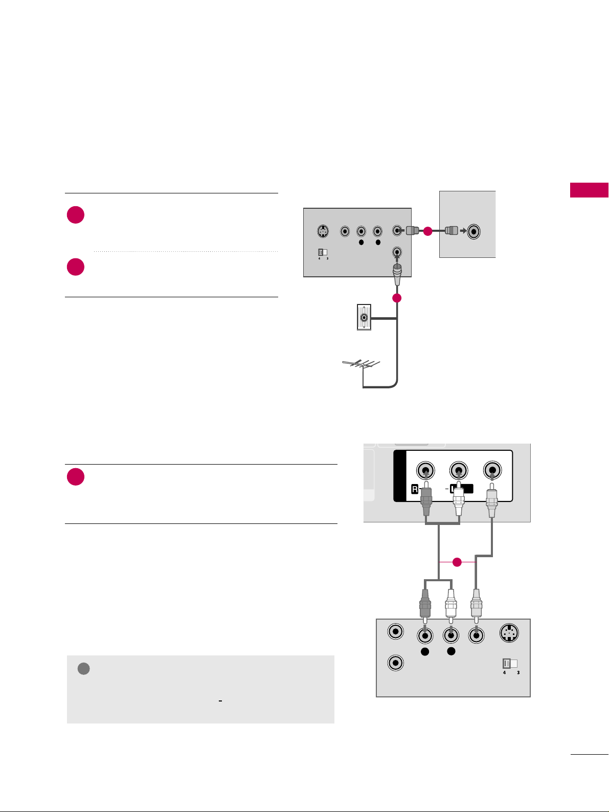
Antenna Connection
■
To avoid picture noise (interference), leave an adequate distance between the VCR and TV.
L R
S-VIDEO VIDEO
OUTPUT
SWITCH
ANT IN
ANT OUT
ANTENNA IN
M.P.I.
Wall Jack
Antenna
1
2
Connect the RF antenna out socket of the
VCR to the
AANNTT EE NNNNAA IINN
socket on the
TV.
Connect the antenna cable to the RF
antenna in socket of the VCR.
1. How to connect
2. How to use
■
Set VCR output switch to 3 or 4 and then
tune TV to the same channel number.
■
Insert a video tape into the VCR and press
PLAY on the VCR. (Refer to the VCR owner’s
manual.
)
2
1
Composite (RCA) Connection
Connect the
AAUUDD II OO/VVII DD EEOO
jacks between TV and
VCR. Match the jack colors (Video = yellow, Audio Left
= white, and Audio Right = red)
1. How to connect
2. How to use
■
Insert a video tape into the VCR and press PLAY on the
VCR. (Refer to the VCR owner’s manual.
)
■
Select the
AAVV 11
input source on the TV using the
IINNPPUU TT
button on the remote control.
■
If connected to
AAVV IINN22
, select
AAVV22
input source on the TV.
1
GG
If you have a mono VCR, connect the audio cable
from the VCR to the
AAUUDDIIOO LL//MMOONNOO
jack of the
TV.
NOTE
!
AUDIO
VIDEO
MONO
/
L
R
S-VIDEO
VIDEO
OUTPUT
SWITCH
ANT IN
ANT OUT
AV IN 1
1
Page 28
EXTERNAL EQUIPMENT SETUP
26
EXTERNAL EQUIPMENT SETUP
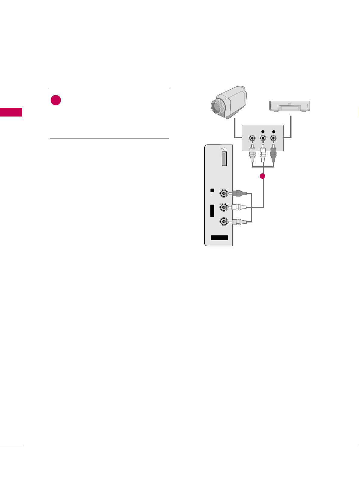
OTHER A/V SOURCE SETUP
Camcorder
Video Game Set
Connect the
AAUUDDIIOO/VVIIDDEEOO
jacks
between TV and external equipment.
Match the jack colors
.
(
Video = yellow, Audio Left = white, and
Audio Right = red
)
1. How to connect
2. How to use
■
Select the
AAVV22
input source on the TV using the
IINNPP UUTT
button on the remote control.
■
If connected to
AAVV IINN11
input, select the
AAVV 11
input source on the TV.
■
Operate the corresponding external equipment.
1
1
USB
SERVICE ONLY
R
AUDIO
L/ MONO
VIDEO
AV IN 2
VIDEO
L R
Page 29
EXTERNAL EQUIPMENT SETUP
27
PC SETUP
GG
To get the best picture quality, adjust the PC graphics card to 1360x768, 60Hz.
GG
Depending on the graphics card, DOS mode may
not work if a HDMI to DVI Cable is in use.
GG
In PC mode, there may be noise associated with the
resolution, vertical pattern, contrast or brightness.
If noise is present, change the PC output to another resolution, change the refresh rate to another
rate or adjust the brightness and contrast on the
PICTURE menu until the picture is clear.
NOTES
!
Supported Display Specifications
(RGB-PC, HDMI-PC)
This TV provides Plug and Play capability, meaning that the PC adjusts automatically to the TV's settings.
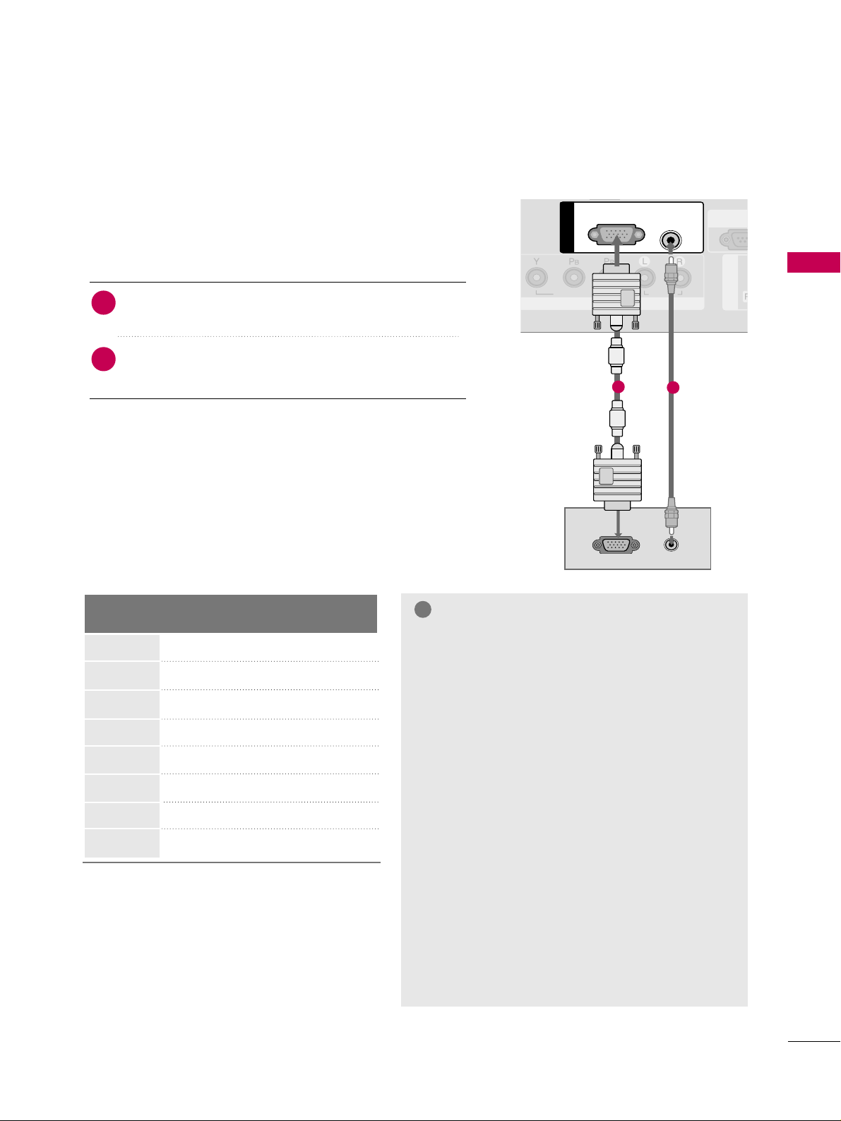
VGA (D-Sub 15 pin) Connection
AV I N 1
COMPONENT IN
VIDEO
RS-23
(SERVIC
AUDIO
RGB IN
RGB OUTPUT
AUDIO
RGB(PC)
AUDIO
(RGB/DVI)
1
2
2. How to use
■
Turn on the PC and the TV.
■
Select the
RRGGBB -- PP CC
input source on the TV using the
IINNPPUU TT
button on the remote control.
Connect the VGA output of the PC to the
RRGG BB ((PP CC
))
jack on the TV.
Connect the PC audio output to the
AAUUDDIIOO ((RRGGBB//DDVVII
))
jack on the TV.
1. How to connect
2
1
Resolution
720x400
1360x768
640x350
640x480
800x600
1024x768
1280x768
1280x1024
Horizontal Vertical
Frequency(KHz)Frequency(Hz
)
31.468 70.09
31.469 70.08
31.469 59.94
37.879 60.31
48.363 60.00
47. 776 59.870
47.712 60.015
63.981 60.020
When you use too long RGB-PC cable, there might
be a noise on the screen.
GG
Avoid keeping a fixed image on the screen for a
long period of time. The fixed image could become
permanently imprinted on the screen.
GG
The synchronization input form for Horizontal and
Vertical frequencies is separate.
GG
Depending on the graphics card, some resolution
settings may not allow the image to be positioned
on the screen properly.
Page 30
EXTERNAL EQUIPMENT SETUP
28
EXTERNAL EQUIPMENT SETUP
DVI to HDMI Connection
U
RESET
LAN
(SERVICE ONLY)
COMPONENT IN
VIDEO
RJP
INTERFACE
AUDIO
HDMI/DVI IN
2
1(DVI)
DVI-PC OUTPUT AUDIO
RGB(PC)
AUDIO
(RGB/DVI)
RGB IN
1
2
2. How to use
■
Turn on the PC and the TV.
■
Select the
HHDDMMII 11
input source on the TV using the
IINNPPUU TT
button on the remote control.
Connect the DVI output of the PC to the
HHDDMMII//DDVVII IINN
11 ((DDVVII))
jack on the TV.
Connect the PC audio output to the
AAUUDDIIOO ((RRGGBB//DDVVII))
jack on the TV.
1. How to connect
2
1
Page 31

EXTERNAL EQUIPMENT SETUP
29
Screen Setup for PC mode
1024 x 768
1280 x 768
1360 x 768
Auto config.
Resolution
G
Position
Size
Phase
Reset
Screen
Move
Prev.
MENU
Selecting Resolution
You can choose the resolution in RGB-PC mode.
The
PP oossiittiioonn, PP hhaa ssee
, and
SS iizzee
can also be adjusted.
Enter
Move
PICTURE
E
RG
• Contrast 50
• Brightness 50
• Sharpness 50
• Color 50
• Tint 0
• Advanced Control
• Reset
Screen (RGB-PC)
Select
PPIICC TTUURREE
.
Select
RRee ssoo lluuttii oonn
.
1
MENU
3
ENTER
4
Select
SSccrree eenn ((RR GG BB -- PP CC))
.
2
ENTER
5
Select the desired resolution.
ENTER
ENTER
Page 32

EXTERNAL EQUIPMENT SETUP
30
EXTERNAL EQUIPMENT SETUP
Auto Configure
Automatically adjusts picture position and minimizes image instability. After adjustment, if the image is still
not correct, try using the manual settings or a different resolution or refresh rate on the PC.
Auto config.
G
Resolution
Position
Size
Phase
Reset
Screen
Move
Prev.
MENU
Auto Config.
• If the position of the image is still not
correct, try Auto adjustment again.
• If picture needs to be adjusted again
after Auto adjustment in RGB-PC, you
can adjust the
PPoossii ttii oo nn, SSiizzee
or
PPhhaass ee
.
Yes No
Select
PPIICC TTUURREE
.
Select
AAuuttoo cc oonn ffiigg..
.
1
MENU
3
ENTER
4
Select
SSccrree eenn ((RR GG BB -- PP CC))
.
2
ENTER 5ENTER
Start Auto Configuration.
Select
YYeess
.
ENTER
Enter
Move
PICTURE
E
RG
• Contrast 50
• Brightness 50
• Sharpness 50
• Color 50
• Tint 0
• Advanced Control
• Reset
Screen (RGB-PC)
Page 33

EXTERNAL EQUIPMENT SETUP
31
Adjustment for screen Position, Size, and Phase
If the picture is not clear after auto adjustment and especially if characters are still trembling, adjust the picture
phase manually.
This feature operates only in RGB-PC mode.
Auto config.
Resolution
Position
G
Size
Phase
Reset
GF
D
E
Screen
Move
Prev.
MENU
■
PPoo ssii ttiioonn
: This function is to adjust picture to left/right and up/down as you
prefer.
■
SSii zzee
: This function is to minimize any
vertical bars or stripes visible on the
screen background. And the horizontal
screen size will also change.
■
PPhh aa ssee
: This function allows you to
remove any horizontal noise and clear or
sharpen the image of characters.
Select
PPIICC TTUURREE
.
Select
PPoo ssii ttiioonn, SSii zzee
, or
PPhhaass ee
.
1
MENU
3
ENTER
4
Select
SSccrree eenn ((RR GG BB -- PP CC))
.
2
ENTER 5ENTER
Make appropriate adjustments.
ENTER
Enter
Move
PICTURE
E
RG
• Contrast 50
• Brightness 50
• Sharpness 50
• Color 50
• Tint 0
• Advanced Control
• Reset
Screen (RGB-PC)
Page 34

EXTERNAL EQUIPMENT SETUP
32
EXTERNAL EQUIPMENT SETUP
Screen Reset (Reset to original factory values)
Returns
PP oossiittiioonn, SS iizz ee
, and
PP hh aass ee
to the default factory settings.
This feature operates only in RGB-PC mode.
Auto config.
Position
Resolution
Size
Phase
Reset
G
Screen
Move
Prev.
MENU
Initialize Settings.
Yes No
Select
PPIICC TTUURREE
.
Select
RReess eett
.
1
MENU
3
ENTER
4
Select
SSccrree eenn ((RR GG BB -- PP CC))
.
2
ENTER 5ENTER
Select
YYeess
.
ENTER
Enter
Move
PICTURE
E
RG
• Contrast 50
• Brightness 50
• Sharpness 50
• Color 50
• Tint 0
• Advanced Control
• Reset
Screen (RGB-PC)
Page 35

Connect one end of the optical or coaxial cable to the
TV’s
OOPPTTIICCAA LL
port of
DDIIGGIITTAALL AAUUDDIIOO OOUUTT
.
Connect the other end of the optical or coaxial cable to
the digital audio input on the audio equipment.
Set the “TV Speaker option - Off” in the AUDIO menu. (
GG
pp..6633
). See the external audio equipment instruction manu-
al for operation.
EXTERNAL EQUIPMENT SETUP
33
AUDIO OUT CONNECTION
Send the TV’s audio to external audio equipment via the Audio Output port.
REMOTE
CONTROL OUT
OPTICAL
DIGITAL
AUDIO OUT
AV IN 1
AUDIO
VIDEO
MONO
/
UPDATE
SPEAKER OUT
8
RS-232C IN
(SERVICE ONLY)
OPTICAL
DIGITAL
AUDIO OUT
1
2
GG
When connecting with external audio equipments, such as
amplifiers or speakers, you can turn the TV speakers off in
the menu. (
GG
pp..6633
)
NOTE
!
G
Do not look into the optical output port. Looking at the
laser beam may damage your vision.
GG
Block the SPDIF out (optical/coaxial) about the contents
with ACP(Audio Copy Protection) function.
CAUTION
1. How to connect
2
3
1
Digital
Page 36

WATCHING TV / CHANNEL CONTROL
34
REMOTE CONTROL FUNCTIONS
WATCHING TV / CHANNEL CONTROL
When using the remote control, aim it at the remote control sensor on the TV.
MUTE
RETURN
CC
TV
POWER
GUIDE
PORTAL
ENTER
VOL
CH
123
456
7809
FLASHBK
VCR
DVD
INPUT
MENU
INFO
i
STB
P
A
G
E
PIP
SAP
PIP CH-
PIP CH+
PIP SWAP
PIP INPUT
ALPHA/NUM
REMOVE
RATIO
TIMER
ABC
DEF
GHI
WXYZ
TUV
PQRS
MNO
JKL
&@
.:/,
POWER
TV/STB/DVD/VCR
GUIDE
PORTAL
INFO
Turns your TV or any other programmed equipment on
or off, depending on mode.
Select the remote’s operating mode: TV, STB, DVD, or
VCR.
Displays and removes electronic channel guide.
Displays and removes hotel interactive menu.
Display information at the top of the screen.
NUMBER
button
— (DASH)
FLASH BACK
VCR/DVD
control buttons
PIP
RATIO
TIMER
SAP
PIP CH +/-
PIP SWAP
PIP INPUT
Navigate the on-screen menus and adjust the system settings to your preference.
Used to enter a program number for multiple program
channels such as 2-1, 2-2, etc.
Tune to the last channel viewed.
Control video cassette recorders or DVD players.
Switches the sub picture Double Window or off mode.
Change the aspect ratio.
GG
pp..4466
Select the amount of time before your TV turns off automatically.
GG
pp..7744
Analog mode: Selects MTS sound (Mono, Stereo, or a
SAP)
GG
pp..6655
DTV mode: Changes the audio language.
Changes the PIP channel.
Exchange the main/sub images.
Select the connected input source for the sub-picture.
Page 37

WATCHING TV / CHANNEL CONTROL
35
Installing Batteries
■
Open the battery compartment cover on the back side and install
the batteries matching correct polarity (+with +,-with -).
■
Install two 1.5V AAA batteries. Don’t mix old or used batteries with
new ones.
■
Close cover.
THUMBSTICK
(Up/Down/Left
Right/ENTER)
RETURN
MENU
INPUT
Navigate the on-screen menus and adjust the system settings to your preference.
Clears all on-screen displays and returns to TV viewing from any menu.
Displays the main menu.
External input modes rotate in regular sequence: TV, AV1-2, Component, RGB-PC,
HDMI1 and HDMI2.
VOLUME UP
/DOWN
CC
MUTE
CHANNEL
UP/DOWN
PAGE
UP/DOWN
Increase/decrease the sound level.
Select a closed caption.
GG
pp..6688
Switch the sound on or off.
GG
pp..3366
Select available channels.
Move from one full set of screen information to the next one.
Page 38

WATCHING TV / CHANNEL CONTROL
36
WATCHING TV / CHANNEL CONTROL
TURNING ON TV
WATCHING TV / CHANNEL CONTROL
NOTE
!
GG
If you intend to be away on vacation, disconnect the power plug from the wall power outlet.
Press the
CCHH((
or ))or
NNUUMMBBEERR
buttons to select a channel number.
1
VOLUME ADJUSTMENT
CHANNEL SELECTION
Press the
VVOOLL ((++
or
--))
button to adjust the volume.
If you want to switch the sound off, press the
MMUUTTEE
button.
You can cancel the Mute function by pressing the
MMUUTTEE
or
VVOOLL ((++
or
--))
button.
Adjust the volume to suit your personal preference.
1
2
3
First, connect power cord correctly.
At this moment, the TV switches to standby mode.
■
In standby mode to turn TV on, press the button on the TV or press
the
PPOOWWEE RR
button on the remote control.
Select the viewing source by using the
IINNPPUUTT
button on the remote control.
■
This TV is programmed to remember which power state it was last set to,
even if the power cord is out.
When finished using the TV, press the
PPOOWWEERR
button on the remote control.
The TV reverts to standby mode.
1
2
3
Page 39

WATCHING TV / CHANNEL CONTROL
37
ON-SCREEN MENUS SELECTION
Your TV's OSD (On Screen Display) may differ slightly from that shown in this manual.
Display each menu.
Select a menu item.
Enter to the pop up menu.
1
MENU
3
2
ENTER
ENTER
Return to TV viewing.
4
MENU
Enter
Move
CHANNEL
CHANNEL
TIME
PICTURE
OPTION
AUDIO
LOCK
Enter
Move
Aspect Ratio : 16:9
Picture Mode : Standard
• Back Light 80
• Contrast 90
• Brightness 50
• Sharpness 60
• Color 60
• Tint 0
PICTURE
E
Enter
Move
Auto Volume : Off
Clear Voice : On
Balance 0
Sound Mode : Standard
•
SRS TruSurround XT:
Off
• Treble 50
• Bass 50
• Reset
AUDIO
E
LR
Enter
Move
Clock :
Feb/21/2008/ 2:10 AM
Off Time : Off
On Time : Off
Sleep Timer : Off
Auto Sleep : Off
TIME
Enter
Move
Lock System : Off
Set Password
Block Channel
Movie Rating
TV Rating-Children
TV Rating-General
Downloadable Rating
Input Block
LOCK
RG
Auto Tuning
Manual Tuning
Channel Edit
Channel Label
Data Broadcasting
Enter
Move
Language : English
Caption : Off
OPTION
Page 40

WATCHING TV / CHANNEL CONTROL
38
WATCHING TV / CHANNEL CONTROL
Auto Scan (Auto Tuning)
Automatically finds all channels available through antenna or cable inputs, and stores them in memory on the
channel list.
Run Auto Tuning again after any Antenna/Cable connection changes.
Select
CC HH AA NN NN EE LL
.
Select
AAuuttoo TTuunniinngg
.
Select
YYeess
.
Run
AAuuttoo ttuunniinngg
.
1
MENU
3
2
ENTER
ENTER 4ENTER
■
A password is required to gain access to
Auto Tuning menu if the Lock System is
turned on.
5
RETURN
Return to the previous menu.
MENU
Return to TV viewing.
Enter
Move
CHANNEL
Auto Tuning
Manual Tuning
Channel Edit
Channel Label
Data Broadcasting
Enter
Move
CHANNEL
Auto Tuning
Manual Tuning
Channel Edit
Channel Label
Data Broadcasting
Press ‘Yes’ button to begin
auto tuning.
Yes
No
CHANNEL SETUP
Page 41

WATCHING TV / CHANNEL CONTROL
39
Select
CC HH AA NN NN EE LL
.
1
MENU
2
ENTER
If selecting DTV or CADTV input signal, you can view the on-screen signal strength monitor to see the quality
of the signal being received.
Add/Delete Channel (Manual Tuning)
Select
MMaa nn uuaa ll TT uunnii nngg
.
Select
DDIIGGII TT AA LL
or
AANNAALLOO GG
.
Select channel you want to add
or delete.
3
ENTER
4
Select
AAdd dd
or
DDee llee tt ee
.
5
ENTER
■
A password is required to gain access to
Manual Tuning menu if the Lock System
is turned on.
6
RETURN
Return to the previous menu.
MENU
Return to TV viewing.
Enter
Move
CHANNEL
Enter
Move
CHANNEL
Auto Tuning
Manual Tuning
Channel Edit
Channel Label
Data Broadcasting
Channel
Select channel type and
RF-channel number.
FF
DIGITAL
GG
FF
2
GG
Close
Delete
DIGITAL 2-1
Bad Normal Good
Auto Tuning
Manual Tuning
Channel Edit
Channel Label
Data Broadcasting
Page 42

WATCHING TV / CHANNEL CONTROL
40
WATCHING TV / CHANNEL CONTROL
Select a channel.
Select channel you want to add or delete.
3
ENTER
4
The channels in the Custom List are displayed in black and the channels deleted from the Custom List are displayed in gray.
Once a channel is highlighted you can add or delete the channel by referring to the small window at the topright corner of the screen.
Channel Editing
Select
CC HH AA NN NN EE LL
.
1
MENU
2
ENTER
Select
CC hh aann nn eell EE ddiitt
.
RETURN
Return to TV viewing.
Return to the previous menu.
5
MENU
Add/Delete
Move Page
CH
Move
Previous
Exit
MENU
Enter
Move
CHANNEL
Auto Tuning
Manual Tuning
Channel Edit
Channel Label
Data Broadcasting
Tune
Page 43

WATCHING TV / CHANNEL CONTROL
41
CHANNEL LABEL
Choose preset labels for your channels.
If a channel label is provided on the signal from the broadcasting station, the TV displays a short name for a
channel even if you didn't preset a label for the channel.
Enter
Move
CHANNEL
Auto Tuning
Manual Tuning
Channel Edit
Channel Label
Data Broadcasting
Enter
Move
CHANNEL
Auto Tuning
Manual Tuning
Channel Edit
Channel Label
Data Broadcasting
Logo
FF
Disney
GG
Channel
DIGITAL 2-1
Close
Select
CC HH AA NN NN EE LL
.
Select
CC hh aann nn eell LLaabb eell
.
Select Channel.
1
MENU
3
2
ENTER
ENTER
Select the appropriate logo for the channel.
5
Select a channel to set logo.
4
6
RETURN
Return to the previous menu.
MENU
Return to TV viewing.
Page 44

WATCHING TV / CHANNEL CONTROL
42
WATCHING TV / CHANNEL CONTROL
INPUT LIST
Select the desired input source.
1
INPUT
TV AV1 AV2
ComponentHDMI1 RGB-PC
TV AV1 AV2 Component RGB-PC
ENTER
■
TT VV
: Select it to watch over-the-air, cable
and digital cable broadcasts.
■
AAVV11--22
: Select them to watch a VCR or
other external equipment.
■
CC oo mmppoonn eenn tt
: Select them to watch
DVD or a Digital set-top box.
■
RRGGBB -- PP CC
: Select it to view PC input.
■
HHDDMMII11--22
: Select them to watch high
definition devices.
HDMI2
Page 45

WATCHING TV / CHANNEL CONTROL
43
EXAMPLE ELECTRONIC PROGRAM GUIDE
This is an example of a typical TV electronic program guide showing available programming.
On The Political Scene
Kids Movies
Top Fashions
World Events Today
Channel 01:30 AM
2:30 AM
2:45 AM 3:00 AM
Kids ...
Kids ...
Kids Movies
K&M
17 XYZ
18 K&M
19 PQX
20 WBD
Mon. 29 May 2009 11:07
New Release
Greatest Hits
Kids
EVENT
CHANNEL
SELECTION
PORTAL
INFO
ENTER
PROGRAMMING GRID
Program listings arranged in
time slots
.
CHANNEL LIST
Shows available
channels in numerical
order.
DATE/TIME OSD
Shows current Date/Time.
CHANNEL INDICATOR
Currently tuned channel
and program.
PROGRAM TITLES
Highlight a title and press
Enter to display additional
program information.
FEATURED ATTRACTION
Highlight and click to get
expanded information.
TV PROGRAM
Current program on selected channel.
Select
GGUUII DD EE
button to shows available TV programs.
1
GUIDE
2
RETURN
Return to TV viewing.
Page 46

PICTURE CONTROL
44
PICTURE CONTROL
PIP (PICTURE-IN-PICTURE)
PIP enables the end user to view two sources on the screen at the same time. The end user can switch
between the Main and Sub picture sizes.
7
8
9
0
PQRS
TUV
WXYZ
PIP CH-
PIP CH+
PIP SWAP
PIP INPUT
PIP
SAP
FLASHBK
TIMER
&@
RATIO
PIP INPUT
Selects viewing source for PIP
window.
PIP SWAP
Switches Main screen and
PIP window sources.
PIP CH-
Selects next lower channel
for PIP window.
PIP CH+
Selects next higher channel
for PIP window.
PIP Operation
1. Connect auxiliary source(s) to TV
connections panel.
2. Enter Installer menu to be sure
source(s) is enabled.
3. Use the interactive remote provided
in the room to operate PIP.
4. Press PIP on remote.
Use the PIP function keys to
operate the available PIP features.
5. To exit PIP mode, simply press PIP.
PIP
Turns PIP mode on and off.
■
Note: Actual size of Main screen and PIP inset may be different than
shown above.
Page 47

PICTURE CONTROL
45
PIP Operation
Use the PIP function keys to operate the available PIP features.
■
Press PIP on remote to place PIP screen inset on the TV screen. See above.
1. With PIP active, press Swap to switch the PIP inset with the TV picture. See above.
Once the PIP inset shows the TV tuner picture, you can select TV channels with PIP Ch+ for channel up
and PIP Ch- for channel down.
2. Press PIP Input to choose from available Aux sources that can be used for the PIP inset.
Note: Not all Aux sources can be used with PIP function.
■
To exit PIP mode press PIP to return to normal one source viewing.
Page 48

PICTURE CONTROL
46
PICTURE CONTROL
PICTURE SIZE (ASPECT RATIO) CONTROL
This feature lets you choose the way an analog picture with a 4:3 aspect ratio is displayed on your TV.
■
RGB-PC input source use 4:3 or 16:9 aspect ratio.
Press the
RRAATTII OO
button repeatedly to select the picture options
:
SSeett BByy PP rr ooggrr aamm,, 44 ::33 ,, 1166::99 ,, ZZoooo mm11,, ZZoooomm 22,, JJuu sstt SS cc aa nn
.
1
RATIO
2
RETURN
Return to TV viewing.
1166 ::99
■
You can also adjust
AAss ppee cc tt RRaattiioo
in
the
PPIICCTTUURREE
menu.
Page 49

PICTURE CONTROL
47
Set by program
Selects the proper picture proportion to match
the source’s image.
4:3
Choose 4:3 when you want to view a picture
with an original 4:3 aspect ratio.
16 : 9
Adjust the picture horizontally, in a linear proportion to fill the entire screen.
(4:3 4:3)
(16:9 16:9)
Page 50

PICTURE CONTROL
48
PICTURE CONTROL
Zoom 1
Choose Zoom 1 when you want to view the picture without any alteration. However, the top and
bottom portions of the picture will be cropped.
Zoom 2
Choose Zoom 2 when you want the picture to be
altered, both vertically extended and cropped.
The picture taking a halfway trade off between
alteration and screen coverage.
Just Scan
Normally the edges of video signals are cropped
1-2%. Just Scan turns off this cropping and
shows the complete video.
Notes: If there is noise on the edges of the original
signal, it will be visible when Just Scan is activated.
JJuusstt SSccaa nn
operates only with
DTV/CADTV/HDMI-DTV/DVI-DTV
(720p/1080i/1080p),
Component(720p/1080i) input sources.
Page 51

PICTURE CONTROL
49
PRESET PICTURE SETTINGS
Picture Mode - Preset
There are factory presets for picture settings available in the user menus. You can use a preset, change each
setting manually.
Enter
Move
PICTURE
E
Aspect Ratio : 16:9
Picture Mode : Standard
• Back Light 90
• Contrast 90
• Brightness 50
• Sharpness 60
• Color 60
• Tint 0
RG
Enter
Move
PICTURE
E
Aspect Ratio : 16:9
Picture Mode : Standard
• Back Light 90
• Contrast 90
• Brightness 50
• Sharpness 60
• Color 60
• Tint 0
RG
Intelligent Sensor
Vivid
Standard
Cinema
Sport
Game
Select
PPIICC TTUURREE
.
Select
IInntteelllliiggeenntt SSeennssoorr, VVii vv iidd
,
SSttaannddaarrdd, CCiinn eemmaa, SSppoorrtt
or
GGaa mmee
.
1
MENU
3
ENTER
Select
PPii cc ttuu rr ee MMoodd ee
.
2
ENTER
4
RETURN
Return to the previous menu.
MENU
Return to TV viewing.
■
When selecting
IInntteell llii gg eenntt SSee nn ssoorr
,
the most suitable picture is automatically
adjusted according to the surrounding
conditions.
■
VVii vv iidd, SSttaannddaarrdd, CCiinn eemmaa, SSppoorrtt
, and
GGaa mmee
Settings are preset for the optimum picture quality at the factory and
are not adjustable.
Page 52

PICTURE CONTROL
50
PICTURE CONTROL
Color Tone - Preset
Choose one of three automatic color adjustments. Set to warm to enhance hotter colors such as red, or set to
cool to see less intense colors with more blue.
Select
PPIICC TTUURREE
.
Select
CC ooll oorr TTeemmppeerraa tt uu rr ee
.
1
MENU
3
ENTER
Select
CC oo ooll, MMeeddii uu mm
, or
WWaarrmm
.
4
Select
AAdd vv aa nn cc eedd CC oonnttrroo ll
.
2
ENTER
5
RETURN
Return to the previous menu.
MENU
Return to TV viewing.
Enter
Move
PICTURE
EE
RG
• Contrast 50
• Brightness 50
• Sharpness 50
• Color 50
• Tint 0
• Advanced Control
• Reset
Screen (RGB-PC)
Enter
Move
PICTURE
E
RG
• Contrast 50
• Brightness 50
• Sharpness 50
• Color 50
• Tint 0
• Advanced Control
• Reset
Screen (RGB-PC)
Color Temperature
FF
Medium
GG
Fresh Contrast
Off
Fresh Color
Off
Noise Reduction
Auto
Gamma
Medium
Black Level
Medium
Eye Care
Off
Close
Film Mode
Off
Page 53

PICTURE CONTROL
51
MANUAL PICTURE ADJUSTMENT
Picture Mode - User Mode
Adjust the picture appearance to suit your preference and viewing situations.
This feature is disable in “
PP iicc ttuurree MMoo ddee--IInn ttee lllliigg eenn tt SS eenn ssoorr
”.
Select
PPIICC TTUURREE
.
Make appropriate adjustments.
Select
BBaa cckk LL iigghh tt,, CCoonnttrraasstt,, BBrriigghhttnn eessss ,,
SShh aarrpp nneessss ,, CCoolloo rr ,, orTTiinntt..
1
MENU
Select
PPii cc ttuu rr ee MMoodd ee
.
2
ENTER
Select
VVii vv iidd,SSttaannddaarrdd, CCiinn eemmaa, SSppoorrtt
or
GGaa mmee
.
3
ENTER
4
ENTER 5ENTER
6
RETURN
Return to the previous menu.
Return to TV viewing.
• Back Light 80
EE
EE
EE
EE
Enter
Enter
Move
PICTURE
E
Aspect Ratio : 16:9
Picture Mode : Standard (User)
• Back Light 90
• Contrast 90
• Brightness 50
• Sharpness 60
• Color 60
• Tint 0
RG
MENU
Page 54

PICTURE CONTROL
52
PICTURE CONTROL
PICTURE IMPROVEMENT TECHNOLOGY
Fresh Contrast: Optimizes the contrast automatically according to the brightness of the reflection.
Fresh Color: Adjusts the color of the reflection automatically to reproduce as close as possible natural colors.
Noise Reduction: Removes interference up to the point where it does not damage the original picture.
Gamma: High gamma values display whitish images and low gamma values display high contrast images.
Select
PPIICC TTUURREE
.
Select
AAdd vv aa nn cc eedd CC oonnttrroo ll
.
Select
FF rreesshh CCoonnttrraass tt, FF rreesshh CCoolloorr
,
NNooiissee RReedd uu cc tt iioonn
, or
GGaamm mmaa
.
1
MENU
3
2
ENTER
ENTER
5
RETURN
Return to the previous menu.
Return to TV viewing.
Select your desired options.
4
Enter
Move
PICTURE
E
RG
• Contrast 50
• Brightness 50
• Sharpness 50
• Color 50
• Tint 0
• Advanced Control
• Reset
Screen (RGB-PC)
MENU
Enter
Move
PICTURE
EE
RG
• Contrast 50
• Brightness 50
• Sharpness 50
• Color 50
• Tint 0
• Advanced Control
• Reset
Screen (RGB-PC)
Color Temperature
Medium
Fresh Contrast
FF
Off
GG
Fresh Color
Off
Noise Reduction
Auto
Gamma
Medium
Black Level
Medium
Eye Care
Off
Close
Film Mode
Off
Page 55

PICTURE CONTROL
53
ADVANCED CONTROL - BLACK (DARKNESS) LEVEL
Adjusting the contrast and the brightness of the screen using the black level of the screen.
This feature is disable in DTV and RGB-PC mode.
Select
PPIICC TTUURREE
.
Select
AAdd vv aa nn cc eedd CC oonnttrroo ll
.
Select
BBllaa cc kk LLeevvee ll
.
1
MENU
3
2
ENTER
ENTER
Select
LLooww
or
HHiigghh
.
4
■
LLooww
: The reflection of the screen gets
darker.
■
HHiigghh
: The reflection of the screen gets
brighter.
■
AAuu ttoo
: Realizing the black level of the
screen and set it to High or Low automatically.
5
RETURN
Return to the previous menu.
MENU
Return to TV viewing.
Enter
Move
PICTURE
E
RG
• Contrast 50
• Brightness 50
• Sharpness 50
• Color 50
• Tint 0
• Advanced Control
• Reset
Screen (RGB-PC)
Enter
Move
PICTURE
EE
RG
• Contrast 50
• Brightness 50
• Sharpness 50
• Color 50
• Tint 0
• Advanced Control
• Reset
Screen (RGB-PC)
Color Temperature
Medium
Fresh Contrast
Off
Fresh Color
Off
Noise Reduction
Auto
Gamma
Medium
Black Level
FF
Low
GG
Eye Care
Off
Close
Film Mode
Off
Page 56

PICTURE CONTROL
54
PICTURE CONTROL
ADVANCED CONTROL - EYE CARE
Dims extremely bright pictures.
This feature is disabled in “
PP iiccttuu rree MMoo ddee --VVii vviidd, CCii nnee mm aa
”.
Enter
Move
PICTURE
E
RG
• Contrast 50
• Brightness 50
• Sharpness 50
• Color 50
• Tint 0
• Advanced Control
• Reset
Screen (RGB-PC)
Enter
Move
PICTURE
EE
RG
• Contrast 50
• Brightness 50
• Sharpness 50
• Color 50
• Tint 0
• Advanced Control
• Reset
Screen (RGB-PC)
Color Temperature
Medium
Fresh Contrast
Off
Fresh Color
Off
Noise Reduction
Auto
Gamma
Medium
Black Level
Low
Eye Care
FF
Off
GG
Close
Film Mode
Off
Select
PPIICC TTUURREE
.
Select
AAdd vv aa nn cc eedd CC oonnttrroo ll
.
Select
EEyy ee CCaarree
.
1
MENU
3
2
ENTER
ENTER
Select
OO nn
or
OO ff ff
.
4
5
RETURN
Return to the previous menu.
MENU
Return to TV viewing.
Page 57

PICTURE CONTROL
55
ADVANCED CONTROL - FILM MODE
Set up the TV for the best picture appearance for viewing movies.
When you operate Film Mode (3:2 Pull-Down Mode or Cinema Correction Mode), the TV will adjust 24 fps
video from movies to 30 fps video for display.
This feature operates only in TV (Analog TV, Digital DTV), AV1, AV2, Component 480i/1080i, and HDMI 1080i
mode.
Select
PPIICC TTUURREE
.
Select
AAdd vv aa nn cc eedd CC oonnttrroo ll
.
Select
FF iillmm MM ooddee
.
1
MENU
3
2
ENTER
ENTER
Select
OO nn
or
OO ff ff
.
4
5
RETURN
Return to the previous menu.
MENU
Return to TV viewing.
Enter
Move
PICTURE
E
RG
• Contrast 50
• Brightness 50
• Sharpness 50
• Color 50
• Tint 0
• Advanced Control
• Reset
Screen (RGB-PC)
Enter
Move
PICTURE
EE
RG
• Contrast 50
• Brightness 50
• Sharpness 50
• Color 50
• Tint 0
• Advanced Control
• Reset
Screen (RGB-PC)
Color Temperature
Medium
Fresh Contrast
Off
Fresh Color
Off
Noise Reduction
Auto
Gamma
Medium
Black Level
Low
Eye Care
Off
Close
Film Mode
FF
Off
GG
Page 58

PICTURE CONTROL
56
PICTURE CONTROL
PICTURE RESET
Settings of the selected picture modes return to the default factory settings.
Select
PPIICC TTUURREE
.
Select
RReess eett
.
Initialize the adjusted value.
1
MENU
3
2
ENTER
ENTER
MENU
Return to TV viewing.
Enter
Move
PICTURE
E
RG
• Contrast 50
• Brightness 50
• Sharpness 50
• Color 50
• Tint 0
• Advanced Control
• Reset
Screen (RGB-PC)
Enter
Move
PICTURE
E
RG
• Contrast 50
• Brightness 50
• Sharpness 50
• Color 50
• Tint 0
• Advanced Control
• Reset
Screen (RGB-PC)
Resetting video configuration...
ii
Page 59

SOUND & LANGUAGE CONTROL
57
SOUND & LANGUAGE CONTROL
AUTO VOLUME LEVELER (AUTO VOLUME)
Auto Volume makes sure that the volume level remains consistent whether you are watching a commercial or a
regular TV program.
Select
AAUUDD II OO
.
Select
AAuuttoo VVoo lluummee
.
Select
OO nn
or
OO ff ff
.
1
MENU
3
2
ENTER
ENTER
4
RETURN
Return to the previous menu.
MENU
Return to TV viewing.
Enter
Move
AUDIO
Auto Volume : Off
Clear Voice : On
Balance 0
Sound Mode : Standard
•
SRS TruSurround XT:
Off
• Treble 50
• Bass 50
• Reset
Enter
Move
AUDIO
Auto Volume : Off
Clear Voice : On
Balance 0
Sound Mode : Standard
•
SRS TruSurround XT:
Off
• Treble 50
• Bass 50
• Reset
LR
LR
Off
On
E
E
Page 60

SOUND & LANGUAGE CONTROL
58
SOUND &LANGUAGE CONTROL
PRESET SOUND SETTINGS (SOUND MODE)
Sound Mode lets you enjoy the best sound without any special adjustment as the TV sets the appropriate
sound options based on the program content.
SS ttaa nndd aarrdd, MM uu ssii cc, CCii nnee mm aa, SS ppoo rr tt
, and
GGaa mmee
are preset for optimum sound quality at the factory and are
not adjustable.
SOUND &LANGUAGE CONTROL
Select
AAUUDD II OO
.
Select
SSoo uu nndd MM ooddee
.
1
MENU
2
ENTER
Select
SSttaa nn dd aarr dd, MM uuss iicc
,
CC iinnee mmaa, SSpp oo rr tt
, or
GGaammee
.
3
ENTER
4
RETURN
Return to the previous menu.
MENU
Return to TV viewing.
Enter
Move
AUDIO
Auto Volume : Off
Clear Voice : On
Balance 0
Sound Mode : Standard
•
SRS TruSurround XT:
Off
• Treble 50
• Bass 50
• Reset
Enter
Move
AUDIO
Auto Volume : Off
Clear Voice : On
Balance 0
Sound Mode : Standard
•
SRS TruSurround XT:
Off
• Treble 50
• Bass 50
• Reset
LR
LR
E
E
Standard
Music
Cinema
Sport
Game
Page 61

SOUND & LANGUAGE CONTROL
59
SOUND SETTING ADJUSTMENT - USER MODE
Adjust the sound to suit your taste and room situations.
Select
AAUUDD II OO
.
Select
SSoo uu nndd MM ooddee
.
Select
TTrree bbllee
or
BBaassss
.
1
MENU
4
2
ENTER
Select
SSttaa nn dd aarr dd, MM uuss iicc
,
CC iinnee mmaa, SSpp oo rr tt
, or
GGaammee
.
3
ENTER
ENTER
Make appropriate adjustments.
5
ENTER
6
RETURN
Return to the previous menu.
MENU
Return to TV viewing.
Enter
Move
AUDIO
Auto Volume : Off
Clear Voice : On
Balance 0
Sound Mode : Standard
•
SRS TruSurround XT:
Off
• Treble 50
• Bass 50
• Reset
Enter
Move
AUDIO
Auto Volume : Off
Clear Voice : On
Balance 0
Sound Mode : Standard
•
SRS TruSurround XT:
Off
• Treble 50
• Bass 50
• Reset
LR
LR
Close
EE
EE
Treble 50
Bass 50
SRS TruSurround XT
Off
E
E
Page 62

SOUND & LANGUAGE CONTROL
60
SOUND &LANGUAGE CONTROL
Enter
Move
AUDIO
LR
SRS TRUSURROUND XT
Select
AAUUDD II OO
.
Select
SSRRSS TT rr uuSSuurrrroouunndd XXTT
.
Select
OO nn
or
OO ff ff
.
1
MENU
3
2
ENTER
ENTER
4
RETURN
Return to the previous menu.
MENU
Return to TV viewing.
Enter
Move
AUDIO
Auto Volume : Off
Clear Voice : On
Balance 0
Sound Mode : Standard
•
SRS TruSurround XT:
Off
• Treble 50
• Bass 50
• Reset
LR
E
E
Auto Volume : Off
Clear Voice : On
Balance 0
Sound Mode : Standard
•
SRS TruSurround XT:
Off
• Treble 50
• Bass 50
• Reset
Treble 50
Bass 50
Close
SRS TruSurround XT
Off
FF
Off
GG
Takes advantage of any multi-channel format without needing to add extra speakers or equipment. Dialog
clarity, bass enrichment, and the addition of stereo audio enhancement produces an immersive sound experience from standard stereo material.
Page 63

SOUND & LANGUAGE CONTROL
61
CLEAR VOICE
By differentiating the human sound range from others, it improves the sound quality of voices.
■
If you select “
CC lleeaarr VVooiicc ee--OOnn
”,
SSRR SS
TTrruuSSuurr rr oouu nn dd XXTT
feature will not work.
Select
AAUUDD II OO
.
Select
CC lleeaarr VVooiicc ee
.
Select
OO nn
or
OO ff ff
.
1
MENU
3
2
ENTER
ENTER
4
RETURN
Return to the previous menu.
MENU
Return to TV viewing.
Enter
Move
AUDIO
Auto Volume : Off
Clear Voice : On
Balance 0
Sound Mode : Standard
•
SRS TruSurround XT:
Off
• Treble 50
• Bass 50
• Reset
Enter
Move
AUDIO
Auto Volume : Off
Clear Voice : On
Balance 0
Sound Mode : Standard
•
SRS TruSurround XT:
Off
• Treble 50
• Bass 50
• Reset
LR
LR
Off
On
E
E
Page 64

SOUND & LANGUAGE CONTROL
62
SOUND &LANGUAGE CONTROL
BALANCE
Select
AAUUDD II OO
.
Select
BBaall aa nn cc ee
.
Make appropriate adjustments.
1
MENU
3
2
ENTER
ENTER
Adjust the left/right sound of speaker to suit your taste and room situations.
4
RETURN
Return to the previous menu.
MENU
Return to TV viewing.
Enter
Move
AUDIO
Auto Volume : Off
Clear Voice : On
Balance 0
Sound Mode : Standard
•
SRS TruSurround XT:
Off
• Treble 50
• Bass 50
• Reset
Enter
Move
AUDIO
Auto Volume : Off
Clear Voice : On
Balance 0
Sound Mode : Standard
•
SRS TruSurround XT:
Off
• Treble 50
• Bass 50
• Reset
LR
LR
Close
EE
EE
Balance : 0
LR
E
E
Page 65

SOUND & LANGUAGE CONTROL
63
TV SPEAKERS ON/OFF SETUP
Turn the TV speakers off if using external audio equipment.
Select
AAUUDD II OO
.
Select
TTVV SS pp eeaakkee rr
.
Select
OO nn
or
OO ff ff
.
1
MENU
3
2
ENTER
ENTER
4
RETURN
Return to the previous menu.
MENU
Return to TV viewing.
Enter
Move
AUDIO
Clear Voice : On
Balance 0
Sound Mode : Standard
•
SRS TruSurround XT:
Off
• Treble 50
• Bass 50
• Reset
TV Speaker : On
Enter
Move
AUDIO
Clear Voice : On
Balance 0
Sound Mode : Standard
•
SRS TruSurround XT:
Off
• Treble 50
• Bass 50
• Reset
TV Speaker : On
LR
LR
EE
Off
On
Page 66

SOUND & LANGUAGE CONTROL
64
SOUND &LANGUAGE CONTROL
AUDIO RESET
Settings of the selected Sound Mode return to the default factory settings.
Select
AAUUDD II OO
.
Select
RReess eett
.
1
MENU
2
ENTER
Initialize the adjusted value.
3
ENTER
Enter
Move
AUDIO
Auto Volume : Off
Clear Voice : On
Balance 0
Sound Mode : Standard
•
SRS TruSurround XT:
Off
• Treble 50
• Bass 50
• Reset
Enter
Move
AUDIO
Auto Volume : Off
Clear Voice : On
Balance 0
Sound Mode : Standard
•
SRS TruSurround XT:
Off
• Treble 50
• Bass 50
• Reset
LR
LR
E E
Resetting audio configuration...
ii
MENU
Return to TV viewing.
4
Page 67

SOUND & LANGUAGE CONTROL
65
Each time you press the
SSAAPP
button,
MM oo nn oo, SStteerr eeoo
, or
SSAAPP
appear in turn.
Return to TV viewing.
1
SAP
2
STEREO/SAP BROADCAST SETUP
For Analog only: This TV can receive MTS stereo programs and any SAP (Secondary Audio Program) that accompanies the stereo program if the station transmits an additional sound signal. Mono sound is automatically used
if the broadcast is only in Mono.
■
If other languages available on the digital signal,
select them with the
SSAAPP
button.
RETURN
MONO SAPSTEREO
Page 68

SOUND & LANGUAGE CONTROL
66
SOUND &LANGUAGE CONTROL
Enter
Move
OPTION
Enter
Move
OPTION
AUDIO LANGUAGE
Other languages may be available if a digital signal is provided by the broadcasting station.
This feature operates only in DTV mode.
Select
OOPPTT II OONN
.
Select
LLaanngguu aa gg ee
.
Select
AAuuddiioo
.
1
MENU
3
2
ENTER
ENTER
Select your desired language:
EEnngg llii sshh, SSpp aann iisshh
, or
FF rreenn cc hh
4
5
RETURN
Return to the previous menu.
MENU
Return to TV viewing.
Language : English
Caption : Off
Menu
English
Audio
FF
English
GG
Close
Language : English
Caption : Off
Page 69

SOUND & LANGUAGE CONTROL
67
Enter
Move
OPTION
Enter
Move
OPTION
ON-SCREEN MENUS LANGUAGE SELECTION
The menus can be shown on the screen in the selected language.
Select
OOPPTT II OONN
.
Select
LLaanngguu aa gg ee
.
Select
MM eenn uu
.
1
MENU
3
2
ENTER
ENTER
Select your desired language.
From this point on, the on-screen menus
will be shown in the selected language.
4
5
RETURN
Return to the previous menu.
MENU
Return to TV viewing.
Language : English
Caption : Off
Language : English
Caption : Off
Menu
FF
English
GG
Audio
English
Close
Page 70

SOUND & LANGUAGE CONTROL
68
SOUND &LANGUAGE CONTROL
CAPTION MODE
Caption must be provided to help people with hearing loss watch TV.
This feature operates only in TV, AV1-2 mode.
Select Caption
OO nn
or
OO ff ff
.
1
CC
ALPHA/NUM
■
When selecting
OO ff ff
, Sub-menus for
Analog, DTV, and Digital Option
become disabled.
Caption must be provided to help people with hearing loss watch TV. Select a caption mode for displaying captioning information if provided on a program. Analog caption displays information at any position on the screen
and is usually the program's dialog. Caption/Text, if provided by the broadcaster, would be available for both
digital and analog channels on the Antenna/Cable. This TV is programmed to memorize the caption/text mode
which was last set when you turned the power off. This function is only available when
CCaappttii oonn
Mode is set
OO nn
.
Analog Broadcasting System Captions
Select
OOPPTT II OONN
.
Select
CC aappttii oonn
.
Select
OO nn
.
1
MENU
3
2
ENTER
ENTER
Select
CC CC11-44
or
TTee xxtt11-44
.
4
■
CC AA PP TT IIOONN
The term for the words that scroll across
the bottom of the TV screen; usually the
audio portion of the program provided
for the hearing impaired.
■
TTEE XXTT
The term for the words that appear in a
large black frame and almost cover the
entire screen; usually messages provided by
the broadcaster.
5
RETURN
Return to the previous menu.
MENU
Return to TV viewing.
Enter
Move
OPTION
Mode
CC1
Close
Digital Option
FF
On
GG
Language : English
Caption : CC1
Enter
Move
OPTION
Language : English
Caption : Off
Page 71

SOUND & LANGUAGE CONTROL
69
Digital Broadcasting System Captions
Choose the language you want the DTV Captions to appear in.
Other Languages can be chosen for digital sources only if they are included on the program.
This function in only available when Caption Mode is set On.
Enter
Move
OPTION
Select
OOPPTT II OONN
.
Select
CC aappttii oonn
.
Select
OO nn
.
1
MENU
3
2
ENTER
ENTER
Select
CC CC11-44, TTee xxtt11-44
, or
SSee rr vviiccee 11- 66
.
4
5
RETURN
Return to the previous menu.
MENU
Return to TV viewing.
Enter
Move
OPTION
Language : English
Caption : Service1
Language : English
Caption : Off
Mode
Service1
Close
Digital Option
FF
On
GG
Page 72

SOUND & LANGUAGE CONTROL
70
SOUND &LANGUAGE CONTROL
Enter
Move
OPTION
Caption Option
Customize the DTV captions that appear on your screen.
This function in only available when Caption Mode is set On.
Select
OOPPTT II OONN
.
Select
CC aappttii oonn
.
Select
OO nn
.
1
MENU
3
2
ENTER
ENTER
Select
CC uu ssttoo mm
.
5
ENTER
Customize the
SSttyyllee, FF oonn tt
, etc., to your
preference. A preview icon is provided at
the bottom of the screen, use it to see the
caption language.
6
Select
DDii ggii ttaall OOppttii oonn
.
4
■
SSii zzee
: Set the word size.
■
FF oonn tt
: Select a typeface for the text.
■
TTee xxtt CC oolloorr
: Choose a color for the
text.
■
TTee xxtt OOpp aa cc iittyy
: Specify the opacity
for the text color.
■
BBgg (( BB aa cc kk gg rroouu nn dd)) CCoolloorr
: Select a
background color.
■
BBgg (( BB aa cc kk gg rroouu nn dd)) OO ppaaccii ttyy
: Select
the opacity for the background color.
■
EEddggee TTyy ppee
: Select an edge type.
■
EEddggee CC oolloorr
: Select a color for the
edges.
7
RETURN
Return to the previous menu.
MENU
Return to TV viewing.
Size
A Standard
Font
Font 1
Text Color
White
Text Opacity
Solid
Bg Color
Black
Bg Opacity
Solid
Close
FF
Custom
GG
Enter
Move
OPTION
Language : English
Caption : Off
Language : English
Caption : Service1
Edge Type
Edge Color
None
Black
Mode
Service1
Close
Digital Option
FF
On
GG
Page 73

TIME SETTING
71
CLOCK SETTING
TIME SETTING
Auto Clock Setup
The time is set automatically from a digital channel signal.
The digital channel signal includes information for the current time provided by the broadcasting station.
Set the clock manually if the current time is set incorrectly by the auto clock function.
Select
TTII MMEE
.
Select
CC lloo cckk
.
Select
AAuu ttoo
.
1
MENU
3
2
ENTER
ENTER
Select your viewing area time zone.
:
EEaass tt eerrnn, CC eennttrraall, MM oouu nn tt aaiinn, PPaa cc iiffii cc
,
AAll aasskk aa
, or
HHaa wwaaiiii
.
4
Select
AAuuttoo, OOffff
, or
OOnn
(depending on whether
or not your viewing area observes Daylight Saving
time).
5
6
RETURN
Return to the previous menu.
MENU
Return to TV viewing.
Enter
Move
TIME
Clock :
Feb/21/2008/ 2:10 AM
Off Time : Off
On Time : Off
Sleep Timer : Off
Auto Sleep : Off
Enter
Move
TIME
Clock :
Feb/21/2008/ 2:10 AM
Off Time : Off
On Time : Off
Sleep Timer : Off
Auto Sleep : Off
Year
Month
2
Date
21
Hour
2 AM
2008
Minute
10
Time Zone
Eastern
Daylight
Saving
Auto
Close
FF
Auto
GG
Page 74

TIME SETTING
72
TIME SETTINGTIME SETTING
Manual Clock Setup
If the current time setting is wrong, set the clock manually.
Select
TTII MMEE
.
Select
CC lloo cckk
.
Select
MM aa nn uuaall
.
1
MENU
3
2
ENTER
ENTER
Select the Year, Month, Date, Hour, or Minute option.
4
Set the Year, Month, Date, Hour, or Minute option.
5
6
RETURN
Return to the previous menu.
MENU
Return to TV viewing.
Enter
Move
TIME
Clock :
Feb/21/2008/ 2:10 AM
Off Time : Off
On Time : Off
Sleep Timer : Off
Auto Sleep : Off
Enter
Move
TIME
Clock :
Feb/21/2008/ 2:10 AM
Off Time : Off
On Time : Off
Sleep Timer : Off
Auto Sleep : Off
Year
Month
2
Date
21
Hour
2 AM
2008
Minute
10
Time Zone
Eastern
Daylight
Saving
Auto
Close
FF
Manual
GG
Page 75

TIME SETTING
73
AUTO ON/OFF TIME SETTING
This function operates only if the current time has been set.
The
OOff ff TT iimmee
function overrides the
OOnn TTiimm ee
function if they are both set to the same time.
The TV must be in standby mode for the
OOnn TTiimm ee
to work.
Select
TTII MMEE
.
Select
OOffff TT iimmee
or
OOnn TTii mmee
.
Select
RRee ppee aatt
.
1
MENU
3
2
ENTER
ENTER
Select
OO ff ff, OOnn cc ee, EEvv eerryy ddaayy, MM oo nn~FF rrii
,
MM oo nn~SSaatt, SSaatt~SSuu nn
, or
SSuunn ddaayy
.
4
Select and set
HHoo uu rr
or
MM iinnuu ttee
.
5
6
RETURN
Return to the previous menu.
MENU
Return to TV viewing.
Enter
Move
TIME
Clock :
Feb/21/2008/ 2:10 AM
Off Time : Off
On Time : Off
Sleep Timer : Off
Auto Sleep : Off
Enter
Move
TIME
Clock :
Feb/21/2008/ 2:10 AM
Off Time : Off
On Time : 6:30 AM (Once)
Sleep Timer : Off
Auto Sleep : Off
Repeat
FF
Once
GG
Hour
6 AM
Minute
30
Close
Page 76

TIME SETTING
74
TIME SETTINGTIME SETTING
SLEEP TIMER SETTING
The Sleep Time turns the TV off at the preset time.
Note that this setting is cleared when the TV is turned off.
Press the
TTIIMMEERR
button repeatedly to select the number of minutes.
Sleep timer options: Off, 10, 20, 30, 60, 90, 120, 180, and 240 minutes.
1
TIMER
2
RETURN
■
You can also adjust
SSll eeee pp TT iimmeerr
in the
TTIIMMEE
menu.
10min
Return to TV viewing.
Page 77

TIME SETTING
75
AUTO SHUT-OFF SETTING
TV will be automatically turned off, in case of no signal for 15 minutes.
Select
TTII MMEE
.
Select
AAuuttoo SS llee eepp
.
Select
OO nn
or
OO ff ff
.
1
MENU
3
2
ENTER
ENTER
4
RETURN
Return to the previous menu.
MENU
Return to TV viewing.
Enter
Move
TIME
Clock :
Feb/21/2008/ 2:10 AM
Off Time : Off
On Time : Off
Sleep Timer : Off
Auto Sleep : Off
Enter
Move
TIME
Clock :
Feb/21/2008/ 2:10 AM
Off Time : Off
On Time : Off
Sleep Timer : Off
Auto Sleep : On
Off
On
TV will be automatically turned off,
in case of No Signal for 15 minutes.
Page 78

PARENTAL CONTROL / RATING
76
PARENTAL CONTROL / RATINGS
Parental Control can be used to block specific channels, ratings and other viewing sources.
The Parental Control Function (V-Chip) is used to block program viewing based on the ratings sent by the broadcasting station. The default setting is to allow all programs to be viewed. Viewing can be blocked by choosing the
type of the program and the categories. It is also possible to block all program viewing for a time period. To use
this function, the following must be done :
1. Set ratings and categories to be blocked.
2. Specify a password
3. Enable the lock
V-Chip rating and categories
Rating guidelines are provided by broadcasting stations. Most television programs and television movies can be
blocked by TV Rating and/or Individual Categories. Movies that have been shown at the theaters or direct-tovideo movies use the Movie Rating System (MPAA)only.
Ratings for Television programs including made-for-TV movies :
■
TV-G(General audience
)
■
TV-PG(Parental guidance suggested
)
■
TV-14(Parents strongly cautioned
)
■
TV-MA (Mature audience only
)
■
TV-Y(All children
)
■
TV-Y7(Children 7 years older
)
Set up blocking schemes to block specific channels, ratings, and external viewing sources.
A password is required to gain access to this menu.
Setting up Your Password
Close
Enter Password
* * * *
Select
LLOO CCKK
.
1
MENU
ENTER
Input the password.
2
123
456
7809
ABC
DEF
GHI
WXYZ
TUV
PQRS
MNO
JKL
&@
.:/,
■
Enter the password as requested.
■
The TV is set up with the initial password “0-0-0-0”.
SET PASSWORD & LOCK SYSTEM
Enter
Move
LOCK
Lock System : Off
Set Password
Block Channel
Movie Rating
TV Rating-Children
TV Rating-General
Downloadable Rating
Input Block
Page 79

PARENTAL CONTROL / RATING
77
Enables or disables the blocking scheme you set up previously.
Lock System
Select
LLoo cc kk SSyysstt eemm
.
Select
OO nn
or
OO ff ff
.
4
3
ENTER
■
When you select
OO nn
, the Lock System
is enable.
Select
LLOO CCKK
.
1
MENU
ENTER
Input the password.
2
123
456
7809
ABC
DEF
GHI
WXYZ
TUV
PQRS
MNO
JKL
&@
.:/,
5
RETURN
Return to the previous menu.
MENU
Return to TV viewing.
Enter
Move
LOCK
Lock System : Off
Set Password
Block Channel
Movie Rating
TV Rating-Children
TV Rating-General
Downloadable Rating
Input Block
Enter
Move
LOCK
Lock System : On
Set Password
Block Channel
Movie Rating
TV Rating-Children
TV Rating-General
Downloadable Rating
Input Block
Off
On
Page 80

PARENTAL CONTROL / RATING
78
PARENTAL CONTROL /RATINGS
Change the password by inputting a new password twice.
Set Password
Select
SSeett ppaass sswwoorrdd
.
Choose any 4 digits for your new password.
As soon as the 4 digits are entered, re-enter
the same 4 digits on the
CC oonnffii rr mm
.
4
3
ENTER
123
456
7809
ABC
DEF
GHI
WXYZ
TUV
PQRS
MNO
JKL
&@
.:/,
Select
LLOO CCKK
.
1
MENU
ENTER
Input the password.
2
123
456
7809
ABC
DEF
GHI
WXYZ
TUV
PQRS
MNO
JKL
&@
.:/,
5
RETURN
Return to the previous menu.
MENU
Return to TV viewing.
Enter
Move
LOCK
Lock System : Off
Set Password
Block Channel
Movie Rating
TV Rating-Children
TV Rating-General
Downloadable Rating
Input Block
Enter
Move
LOCK
Lock System : Off
Set Password
Block Channel
Movie Rating
TV Rating-Children
TV Rating-General
Downloadable Rating
Input Block
Close
New
* * * *
Confirm
* * * *
Page 81

PARENTAL CONTROL / RATING
79
CHANNEL BLOCKING
Select
BBll oocckk CChhaannnnee ll
.
Select a channel to block or unblock.
4
3
ENTER
Block or unblock a channel.
5
Blocks any channels that you do not want to watch or that you do not want your children to watch.
Select
LLOO CCKK
.
1
MENU
ENTER
Input the password.
2
123
456
7809
ABC
DEF
GHI
WXYZ
TUV
PQRS
MNO
JKL
&@
.:/,
6
MENU
Return to the previous menu.
RETURN
Return to TV viewing.
Block/Unblock
Enter
Move
LOCK
Lock System : Off
Set Password
Block Channel
Movie Rating
TV Rating-Children
TV Rating-General
Downloadable Rating
Input Block
Move Page
CH
Move
Previous
Exit
MENU
Tune
Page 82

PARENTAL CONTROL / RATING
80
PARENTAL CONTROL /RATINGSPARENTAL CONTROL /RATINGS
MOVIE & TV RATING
Movie Rating (MPAA)
Blocks movies according to the movie ratings limits specified, so children cannot view certain movies. You can
set the ratings limit by blocking out all the movies with the ratings above a specified level. Keep in mind that
the movie ratings limit only applies to movies shown on TV, not TV programs, such as soap operas.
Select
MM oovviiee RRaa ttiinngg
.
Select GG,
PP GG, PPGG--1133, RR, NNCC--1177
,
XX
, or
BBll oocckkiinngg OOffff
.
4
3
ENTER
■
G (General audience)
■
PG (Parental guidance suggested)
■
PG-13 (Parents strongly cautioned)
■
R (Restricted)
■
NC-17 (No one 17 and under admitted)
■
X (Adult only)
■
Blocking Off (Permits all programs)
GG
If you set PG-13: G and PG movies will
be available, PG-13, R, NC-17 and X will
be blocked.
Select
LLOO CCKK
.
1
MENU
ENTER
Input the password.
2
123
456
7809
ABC
DEF
GHI
WXYZ
TUV
PQRS
MNO
JKL
&@
.:/,
5
RETURN
Return to the previous menu.
MENU
Return to TV viewing.
Enter
Move
LOCK
Lock System : Off
Set Password
Block Channel
Movie Rating
TV Rating-Children
TV Rating-General
Downloadable Rating
Input Block
Enter
Move
LOCK
Lock System : Off
Set Password
Block Channel
Movie Rating
TV Rating-Children
TV Rating-General
Downloadable Rating
Input Block
G
PG
PG-13
R
NC-17
X
Blocking Off
Blocking Off : Permits all programs
Page 83

PARENTAL CONTROL / RATING
81
Select
TTVV RR aattii nn gg--CChhiilldd rr eenn
.
Select
AAgg ee
or
FF aann ttaassyy VVii oolleennccee
.
4
3
ENTER
Select block options.
5
ENTER
■
Age (applies to TV-Y, TV-Y7)
■
Fantasy Violence (applies to TV-Y7)
TV Rating Children
Prevents children from watching certain children's TV programs, according to the ratings limit set. The children
rating does not apply to other TV programs. Unless you block certain TV programs intended for mature audiences in the TV Rating - sub menu, your children can view those programs.
Select
LLOO CCKK
.
1
MENU
ENTER
Input the password.
2
123
456
7809
ABC
DEF
GHI
WXYZ
TUV
PQRS
MNO
JKL
&@
.:/,
Enter
Move
LOCK
Lock System : Off
Set Password
Block Channel
Movie Rating
TV Rating-Children
TV Rating-General
Downloadable Rating
Input Block
Enter
Move
LOCK
Lock System : Off
Set Password
Block Channel
Movie Rating
TV Rating-Children
TV Rating-General
Downloadable Rating
Input Block
Close
Age
Fantasy Violence
6
RETURN
Return to the previous menu.
MENU
Return to TV viewing.
Page 84

PARENTAL CONTROL / RATING
82
PARENTAL CONTROL /RATINGS
TV Rating General
Based on the ratings, blocks certain TV programs that you and your family do not want to view.
Select
AAgg ee, DDii aa lloo gguuee, LLaanngg uu aagg ee
,
SSee xx
or
VVii oolleennccee
.
4
3
ENTER
Select block options.
5
■
Age (applies to TV-G,TV-PG,TV-14,TVMA).
■
Dialogue-sexual dialogue (applies to
TV-PG,TV-14).
■
Language-adult language (applies to
TV-PG, TV-14, TV-MA).
■
Sex-sexual situations (applies to TV-PG,
TV-14, TV-MA).
■
Violence (applies to TV-PG, TV-14, TVMA).
Select
LLOO CCKK
.
1
MENU
ENTER
Input the password.
2
123
456
7809
ABC
DEF
GHI
WXYZ
TUV
PQRS
MNO
JKL
&@
.:/,
6
RETURN
Return to the previous menu.
MENU
Return to TV viewing.
Enter
Move
LOCK
Lock System : Off
Set Password
Block Channel
Movie Rating
TV Rating-Children
TV Rating-General
Downloadable Rating
Input Block
Enter
Move
LOCK
Lock System : Off
Set Password
Block Channel
Movie Rating
TV Rating-Children
TV Rating-General
Downloadable Rating
Input Block
Close
Age
Dialogue
Language
Sex
Violence
PARENTAL CONTROL /RATINGS
Select
TTVV RR aattii nngg--GGeenneerraa ll
.
Page 85

PARENTAL CONTROL / RATING
83
DOWNLOADABLE RATING
■
Based on rating table, your TV's OSD
(On Screen Display) may differ slightly
from what is shown in this manual.
This function may become available in the future and will be available only for digital channels.
This function operates only when TV has received Region5 Rating data.
Select
DDoowwnnllooaa ddaabb llee RRaattii nn gg
.
Select desired
DDoowwnnll ooaaddaabb llee
RRaattiinn gg
option.
4
3
ENTER
Select desired option and block it.
5
ENTER
Select
LLOO CCKK
.
1
MENU
ENTER
Input the password.
2
123
456
7809
ABC
DEF
GHI
WXYZ
TUV
PQRS
MNO
JKL
&@
.:/,
6
RETURN
Return to the previous menu.
MENU
Return to TV viewing.
Enter
Move
LOCK
Lock System : Off
Set Password
Block Channel
Movie Rating
TV Rating-Children
TV Rating-General
Downloadable Rating
Input Block
Enter
Move
LOCK
Lock System : Off
Set Password
Block Channel
Movie Rating
TV Rating-Children
TV Rating-General
Downloadable Rating
Input Block
Humor
Sport
Cruelty
Language
Sadness
Genre
Age
Close
E
E
Page 86

PARENTAL CONTROL / RATING
84
PARENTAL CONTROL /RATINGSPARENTAL CONTROL /RATINGS
EXTERNAL INPUT BLOCKING
Enables you to block an input.
Select
IInnpp uutt BBlloocckk
.
Select input source.
4
3
Select
OO nn
or
OO ff ff
.
5
ENTER
Select
LLOO CCKK
.
1
MENU
ENTER
Input the password.
2
123
456
7809
ABC
DEF
GHI
WXYZ
TUV
PQRS
MNO
JKL
&@
.:/,
6
RETURN
Return to the previous menu.
MENU
Return to TV viewing.
Enter
Move
LOCK
Lock System : Off
Set Password
Block Channel
Movie Rating
TV Rating-Children
TV Rating-General
Downloadable Rating
Input Block
Enter
Move
LOCK
Lock System : Off
Set Password
Block Channel
Movie Rating
TV Rating-Children
TV Rating-General
Downloadable Rating
Input Block
AV1
FF
Off
GG
AV2
Off
Component
Off
HDMI1
Off
RGB-PC
Off
Close
HDMI2
Off
Page 87

COMMERCIAL MODE SETUP
85
INTERACTIVE TV SETUP
COMMERCIAL MODE SETUP
Set up the TV for Gem PPV or Gem Operation without a PPV card
Channel Guide
Hotel Information
Help
Exit
PPV GEM-TV Setup
1. Make all connections as required of PPV system.
2. Set TV to default condition.
3. Configure all relevant installer menu items and TV features.
4. Install PPV card. In most cases the PPV card is preprogrammed with the PPV
provider master TV setup.
GEM-TV Setup Without PPV Card
Refer to Commercial Mode Setup on page 88.
1. See installer menu pages and make settings as required for Gem operation.
2. Specify a Gem Start Channel for item 118 that will tell the TV which channel
to tune in for Gem operation.
3. Set TV features on TV Channel, Picture, Audio etc. menus as indicated on
page 88.
Gem Operation Interactive Menu Features
Use the Gem remote provided in the room to operate both interactive menu and
the regular TV features.
Channel Guide
Shows available TV programs. Indicates channel, program start and finish time
and identifies the TV network.
Hotel Information
Shows typical hotel information. Such as photos of Guestroom, Dining, Business
Center, Fitness, Pool, and Facility. And any contributing Partners such as local
schools in co-operation programs with the lodge.
Help
Offers explanation for interactive menu operation with provided IR remote.
Exit
Removes the interactive menu from the screen.
Note: TV clock must be set before Gem data can be downloaded.
1
2
3
4
5
6
7
8
9
0
ABC
DEF
GHI
JKL MNO
PQRS
TUV
WXYZ
PIP CH-
PIP CH+
PIP SWAP
PIP INPUT
PIP
SAP
FLASHBK
REMOVE
ALPHA/NUM
P
A
G
E
MUTE
TIMER
MENU
RETURN
VOL
CH
POWER
GUIDE
INPUT
CC
ENTER
TV
DVD
VCR
STB
&@
.:/,
RATIO
PORTAL
INFO
i
Page 88

COMMERCIAL MODE SETUP
86
COMMERCIAL MODE SETUP
INSTALLER OVERVIEW
This is the commercial mode setup guide only.
Operating Installer Menu
To set up the controls for the TV you will need to know how to
enter the TV Installer menu and make changes to the default values as required. If necessary, familiarize yourself with the TV
Installer menu and how to make and save changes in the menu.
LG Installer Remote
You will need an
LLGG II nnssttaall llee rr rree mmoottee
control similar to the one
shown to the right. The installer remote must have a “Source” button or its equivalent. The remote shown in this manual has
“INPUT” -- this button serves the purpose of a Source button.
The TV’s clonable features need to be set up. This is a critical
step. If the Master TV display panel’s clonable features like adding
channel icons or channel labels are not done correctly, then the
cloned TVs will all have problems. Refer to the Owner’s Manual for
other TV features: Video, Audio, Closed captions, V-Chip, etc.
TLL-1100A Clone Programmer
The TLL is a very simple cloner to use. It can be set up to clone a
master TV setup and transfer it into a target TV. Cloning is accom-
plished using the TV/Cloner MPI ports for communication. Be sure the Master TV is set up completely. Cloning is only possible when the TV is tuned
to an Analog channel, not a digital channel.
Typical Installer Menu
TV Link
Loader-Demo
TLL1100A
Ready
TLL1100A
ENTER
RECEIVE SEND
MENU
MODE
000 INSTALLER SEQ 000
UPN 000-000-000-000 FPGA E0F1
PTC V1.00.000 CPU V3.06.00
GEM PTC INSTALLER MENU
1
2
3
4
5
6
7
8
9
0
ABC
DEF
GHI
JKL MNO
PQRS
TUV
WXYZ
PIP CH-
PIP CH+
PIP SWAP
PIP INPUT
PIP
SAP
FLASHBK
REMOVE
ALPHA/NUM
P
A
G
E
MUTE
TIMER
MENU
RETURN
VOL
CH
POWER
GUIDE
INPUT
CC
ENTER
TV
DVD
VCR
STB
&@
.:/,
RATIO
PORTAL
INFO
i
Page 89

COMMERCIAL MODE SETUP
87
INTERACTIVE TV OVERVIEW
Through the interactive TV, the lodging guest is offered a more complete
venue of lodge services and amenities. Using the TV in the comfort of the
hotel room, the guest can browse the lodge resources available and make
selections quickly. Charges for these offerings are billed at the time of reservation. The Gem TV is connected to the lodge’s billing computer.
After the interactive TV is installed, the following hotel and other resources
may be available to the hotel guest, assuming that they are provided by the
lodge.
Interactive Amenities may include the following
■
Hotel Information, News and Events.
■
Directory Services, (Tourist attractions, Restaurants, etc.)
■
Reservation Service (Business Meetings, Fitness, SPA, etc.)
■
Weather, Traffic Information.
■
Shopping Services (Delivery to Guest Room)
■
Room Service (Menu Ordering, Memo Service, Morning Wake Up Call, Laundry, etc.)
■
Ticketing Services.
■
Check Out Service (in the Guest Room).
■
Gaming Services.
■
Email resources, guest can access an email account, etc.
■
Other offerings as they become available.....
Channel Guide
Hotel Information
Help
Exit
Gem Interactive TV Notes
GGEEMM--TTVV SS eettuupp ff oorr PP PP VV
((PP aayy -- ppee rr--vviiee ww)) OOppee rr aattii oonn
A PPV card usually has a channel lineup included with the
master TV setup. If this is the
case, reset TV to default condition, set any TV features and
installer menu items as
required and then insert the
PPV pre-programmed card into
the MPI slot.
■
After TV setup, remove the AC
power cord for 15 seconds.
IImmppoorrttaa nn tt !!
■
The TV will take a few minutes
to load electronic program
information. If enough time
has not elapsed for the TV to
acquire EPG data, the TV may
operate erratically; menus
may not work or TV will not
respond to IR remote key
presses.
■
If Pseudo Power Off is active,
actual TV power cycle will not
occur until pseudo power off
has timed out.
Page 90

COMMERCIAL MODE SETUP
88
COMMERCIAL MODE SETUP FOR MASTER TV
COMMERCIAL MODE SETUP
NNoottee 11
: Disconnect all Aux inputs. Under certain conditions, Auto
Tuning (Channel search) is disabled if there is an Aux input active.
Commercial Mode Setup Procedure
1. Set Installer Menu Items
(Enter TV Installer Menu, see Installer menus for detailed instructions.)
a. Set Installer menu item
111177 FFAACCTT DDEE FFAAUULLTT
,to
0000 11
and press
EENNTTEERR
on Installer remote. (This clears all installer menu custom
settings, channel labels / icons etc. and reloads the factory default
settings.)
b. Set Item
000033 BBAANNDD//AAFFCC
.
-
BBrrooaadd ccaasstt
: set to
0000 00
.-
HHRR CC
: set to
0000 22
-
CC AA TT VV
: set to
0000 11
.-
IIRR CC
: set to
0000 33
c. Set item
002288 CCHH OOVVEERRIIDDEE
to
0000 11
. This allows access to channel search, Auto Tuning and Channel List/Edit options in the
Channel Menu.
d. Set other particular installer items that affect your TV programming
network. Enable/Disable Aux sources, set a
GGeemm SSttaarrtt CChhaannnneell
etc.
e. After all required installer menu item settings have been adjusted,
press ENTER on the remote to remove Installer Menu.
2. Set Up TV Features
(Channel, Picture, Audio, Lock, Time, Option, Digital Captions etc.
See TV Clonable options list and TV menus pages.)
3. Run Auto Tuning (Channel Search)
(Search for all available channels.) Go to the Channel menu and
access the Auto Tuning option, follow onscreen instructions.
a. Edit Channel Scan. In the Channel Menu, access Channel Edit
option.
■
Add/Delete channels per your system requirements.
Note: Physical channel numbers are used to identify Virtual channels.
■
Add familiar channel trademarks/logos like ABC, CBS, NBC etc. to
the Channel-Time onscreen display. In the Channel menu, select the
Channel Label option. Add identifiable labels (logos) for the end
user to readily know what common networks are available.
4. Transfer TV Setup to Internal TV Controller: 2-5-5 + Menu Mode
After the TV channel scan has been edited and channel label icons
added, enter the Installer menu. Once in the Installer menu, press 2-55 and MENU on the remote. This transfers the TV setup to the internal controller box.
5 . Add Custom Channel Labels for Analog Channels: 2-5-4 + Menu Mode
Enter Installer menu, press 2-5-4 and MENU. Add your own custom
text labels to channel onscreen displays. Note: Digital Channels often
have a broadcaster generated label. (See 2-5-4+Menu pages.)
When finished, to exit 2-5-4+Menu mode, press
MM EENNUU
.
Verify TV Setup
At this point, verify that the channel lineup, channel icons and custom
labels are correct. Make sure the TV features are set per your requirements. Set item
002288 CChh OOvveerriidd ee
to
0000 00
to lock the channel scan.
After the preceding has been completed, the Master TV setup is ready
to be copied to a Clone Programmer, see cloning options pages.
003 BAND/AFC 00X
028 CH. OVERIDE 001
117 FACT DEFAULT 00X
Typical TV Installer Menu
Adjust the settings for
these Installer Menu Items
DIGITAL 19-3
WXYZ
MONO
STEREO SAP
Custom Text Label ‘WXYZ’ created in
2-5-4 + Menu (Add Channel Label)
Mode
028 CH. OVERIDE 000
After Master TV setup has been
completed, set item 028 Ch
Overide to 000.
000 INSTALLER SEQ 000
UPN 000-000-000-000 FPGA E0F1
PTC V1.00.000 CPU V3.06.00
GEM PTC INSTALLER MENU
093 RJP AVAILABLE 001
Set 093 RJP Available to 001 if
using a remote jack pack
This page provides an overview of a Master TV configuration.
Page 91

COMMERCIAL MODE SETUP
89
On Master TV, Create Profile and Learn
MASTER TV PROFILE SETUP LEARNING/TEACHING WITH USB MEMORY CARD
LEARN MODE
Choose the name of the image file:
37LG700H_UA_ a a c c c .TLL
1. Set up all Master TV features on the menus and do
a Channel Search. Add Channel and Aux Labels etc.
Tune in an analog channel.
2. Plug USB memory card into the USB In port on
Master TV.
3. Press Menu key to open Main menu. Highlight the
Option icon.
4. Press the Left arrow key once, the Option icon on
left side of menu will be highlighted.
5. Press number key ‘7’ a total of 7 times.
6. Key in password* used to enter Installer Menu.
7. Using Up/Down arrow key, highlight “Learn From
TV”, then press Enter.
8. To identify the profile from others, you can change
the last 5 digits. Key in a custom file name, then
press the Enter key.
9. The Learning status will be shown on progress bar.
As soon as learning the current profile is complete,
a message will appear on screen indicating the
learning process is done.
10. Remove the USB memory card.
Learn from TV
Learning current profile from master TV:
20%
Don't remove the USB memory card.
Do not unplug!
* See Installer Menu pages.
NOTES
!
GG
Do not remove TV power cord or USB memory
card while Learning, doing so might harm your
USB memory card.
GG
Do not remove TV power cord or USB memory
card while Teaching, doing so may cause the TV
to malfunction.
GG
You are allowed to edit the file name, however, a
file with edited contents will not be recognized.
GG
Since clock data is copied into USB memory card
as numeric data, the time difference between
teaching and learning is not automatically adjusted. Either set the clock manually, or use Auto
Clock set on TV main menu.
Optional: Edit/Change File Name
If necessary, the file name can be edited or changed.
USB Download Menu
Select a type of sofware to be downloaded:
Upgrade TV Software
Upgrade PTC Software
Teach To TV
Learn From TV
Page 92

COMMERCIAL MODE SETUP
90
COMMERCIAL MODE SETUP
1. Plug USB memory card with Master TV Profile setup
into Target TV USB input por t.
2. Press Menu key to open Main menu and then highlight the Option Menu icon.
3. Press the Left arrow key once, this will highlight the
Option icon on left side of menu.
4. Press number key ‘7’, a total of 7 times.
5. Using the Up/Down arrow key, select ‘Teach to TV’,
then press Enter key.
6. Use Up/Down arrow keys to navigate through profiles. Select the profile that you want to install by
highlighting it and pressing the Enter key.
7. Teaching progress will be shown on the progress bar.
As soon as teaching is done, a message will appear
indicating that the teaching process has been completed.
TEACH MODE
Teaching the selected profile to the TV:
20%
Don't remove the USB memory card.
Do not unplug!
On Target TV, Teach Master TV Profile
TEACH MODE
The following software files are found in the memory card.
Select the file you want to download to this TV.
Or, Press EXIT to cancel the upgrade.
Software File List in USB Memory
37LG700H-UA
■
Image shown may differ from your TV.
Page 93

COMMERCIAL MODE SETUP
91
TLL-1100A CLONING CONNECTIONS/LEARNING SETUP
Connections for the TLL-1100A Clone Programmer to Learn the TV Master TV Setup
On Master TV
Set up all Master TV features on the
menus and do a Channel Search.
Add Channel and Aux labels etc. See
previous page. Insert MPI cable into
TV MPI port.
On TLL-1100A
1. Turn On the TLL-1100A.
2. Use the Mode button to select
Clone Mode.
3. Use the Left/Right arrow to
select the CBank (1 - 8) to store
the master setup in.
4. Plug the other end of the MPI
cable into the MPI port on the
bottom of the TLL.
5. With the Installer remote control,
select item 1 on TLL menu.
6. Press Enter, to transfer the
Master setup into CBankX on the
TLL. The TLL will copy the master
setup.
7. When learning is done, disconnect MPI cable from Master TV.
On Target TV
1. Connect MPI cable from the TLL
to the MPI port on the Target
TV. Assure that the correct
CBank(X) is selected on TLL..
2. With the Installer remote control select item 2, to Teach the
target TV the master TV setup.
3. Press Enter to begin teaching.
4. When Teaching is done, disconnect MPI cable and power the TV
Off. Unplug TV power cord.
5. Reconnect TV power cord. Power
the TV On and the master setup
should be resident on the TV.
Antenna
(or CATV)
Antenna
(or CATV)
TV Link
Loader-Demo
TLL1100A
Ready
TLL1100A
ENTER
RECEIVE SEND
MENU
MODE
CLONE SELECTION MENU
Selected Bank: CBank X Saved
(1) LEARN FROM TV
(2) TEACH TO TV
(3) SET CLONE CLOCK FROM TV
(4) SET TV CLOCK FROM CLONE
(5) DISPLAY TV SETUP
(6) DISPLAY CLONE SETUP
CLONE CLOCK = 00:00
TV CLOCK = 00:00
THE CLONE IS VERSION V2.2.2
-To change menu items, Press
channel keys or digits.
-To execute item, Press ENTER.
M.P.I. Learning Setup
M.P.I. Teaching Setup
TV Link
Loader-Demo
TLL1100A
Ready
TLL1100A
ENTER
RECEIVE SEND
MENU
MODE
NOTE
!
GG
It is assumed that the TV is connected to a signal source, the TV
source selected is Antenna (RF) In, the signal is from an Analog
channel, not a digital channel, all equipment is connected to power
and turned on and the TLL Cloner main menu is displayed on the
TV screen, see above.
G
Do not use the TLL-1100A while any PPV card is installed
in TV or clone programmer device will be damaged.
Warning
Page 94

COMMERCIAL MODE SETUP
92
LT2002 CLONING CONNECTIONS/LEARNING SETUP
COMMERCIAL MODE SETUP
Connections for the LT2002 Clone Programmer to Learn the TV Master TV Setup
Before you begin cloning...
■
The Master TV should be connected to a good, stable
signal from an over-the-air antenna or cable service
Analog
channel and connected to power. (See above.)
■
Teaching and Learning is only possible between identical model devices. (However, the LT2002 Clone programmer can store up to 3 different ‘master’ setups.)
WARNING: Copying a blank or incorrect memory into
a TV, STB or other device will cause the TV, STB or
other device to operate erratically or become inoperable.
■
Use an Installer’s remote to operate Learning and
Teaching menus.
■
Make sure that the batteries in the Clone programmer
are fresh.
■
If batteries are removed, the Clone Clock time will be
lost.
■
Decide if you want to set the time from the Clone
programmer or copy the time to the Clone programmer; from a compatible TV which has the clock set to
the current time.
■
Setting the time and transferring it to the Clone or
other device is a separate procedure.
■
Follow the connection diagram above to connect the
Clone to a Master TV TV display panel. After learning
is complete, to another identical TV TV display panel
to “teach” it the master setup.
■
See the Clone Troubleshooting section to resolve
problems.
Turn to the next page to continue Cloning Setup.
G
Do not use LT2002 while any PPV card is installed in TV or clone programmer device will be damaged.
Warning
NOTE
!
GG
It is assumed that the TV is connected to a signal source, the source selected is Antenna (RF) In, the signal
is from an Analog channel, not a digital channel, all equipment is connected to power and turned on and
the LT2002 Clone Programmer main menu (THE CLONE HAS CONTROL OF THE TV) menu is displayed on
the TV screen, see above and next page.
Antenna
or CATV
THE CLONE HAS CONTROL OF THE TV
THE CLONE IS VERSION XX
THE TV IS VERSION XX
THE SW IS REVISION XX
CLONE CLOCK = XX:XX
TV CLOCK = XX:XX
-PRESS ANY KEY TO CONTINUE.
-DISCONNECT CLONE WHEN DONE.
Ferrite Core
(TDK, ZCAT
2035-0930)
Connect cable to
TV MPI Jack and
follow on screen
instructions
QuickSet II Programmer
Status
Indicator
MPI
Color
• green battery ok
• red battery low
Blink pattern
• slow power on
no communications
• heartbeat power on
communications ok
LT2002
Reset
Clone Programmer
Master TV
Page 95

COMMERCIAL MODE SETUP
93
LT2002 CLONING LEARNING SETUP
Learning the Master TV Setup
Use MPI Cable to Connect LT2002 Clone
Programmer to Master TV MPI Port
If there is a good connection, “THE CLONE HAS
CONTROL OF TV”
message will appear. Press any key on the Installer remote.
Learn Setup from Master TV
Press 1 to select the “LEARN FROM TV” option, then
press ON/OFF, POWER, or ENTER to go to the Memory
Bank Selection Menu. Pick the Memory ”Bank” you want to
store the master TV’s setup in by pressing either Channel
key repeatedly to choose Memory 1, 2 or 3. (If you
choose a Memory “Bank” that has a master device’s setup
programmed into it, that setup will be overwritten by the
new master TV’s setup.) Once the Clone memory bank is
selected, press ON/OFF, POWER, or ENTER. The Clone
memory bank you have selected will be shown. Press
ON/OFF or POWER to begin copying the master TV’s
setup.
Set the Clock (Optional)
Set the time on a Master TV’s Clock. (If the time has
already been copied from a TV into the Clone programmer,
you can set a master TV’s clock by copying the time from
the Clone programmer.) The Clone Programmer can copy
the current time to both a master TV and to the Clone’s
internal clock; accurate to within one minute. (Another reason that the Clone programmer should be equipped with
fresh, high-quality alkaline batteries, is for it to keep the
time as accurately as possible.)
Since the Clone Programmer’s time cannot be set directly,
the current time needs to be copied from a Zenith/LG TV
equipped with M.P.I. input capability.
After the time is copied to the Clone programmer, the current time can then be transferred to another TV. (This can
be a master TV, or another TV which has already had the
features set up.)
LT2002 Clone Programmer Communication
Problems
■
A slow flashing green light indicates there are
communication problems between the TV and
the LT2002 clone programmer. If this is the
case, check for a damaged cable, poor contacts,
or other connection troubles.
■
If the status indicator is red, the programmer
batteries are low and should be replaced. Install
4 high-quality alkaline AA batteries.
THE CLONE HAS CONTROL OF THE TV
THE CLONE IS VERSION XX
THE TV IS VERSION XX
THE SW IS REVISION XX
CLONE CLOCK= XX:XX
TV CLOCK= XX:XX
-PRESS ANY KEY TO CONTINUE.
-DISCONNECT CLONE WHEN DONE.
CLONE SELECTION MENU
(1) LEARN FROM TV
(2) TEACH TO TV
(3) SET CLONE CLOCK FROM TV
(4) SET TV CLOCK FROM CLONE
(5) DISPLAY TV SETUP
(6) DISPLAY CLONE SETUP
-TO CHANGE MENU ITEMS, PRESS
CHANNEL KEYS OR DIGITS.
-TO EXECUTE ITEM, PRESS ON/OFF,
POWER, OR ENTER
This menu should appear by itself after
the LT2002 is connected to the TV MPI
port.
This menu should appear after any key is
pressed on the Installer remote.
Instructions for the Clone Programmer to Learn the Master TV Setup
Page 96

COMMERCIAL MODE SETUP
94
CLONING CONNECTIONS/TEACHING SETUP
COMMERCIAL MODE SETUP
Teaching the Master Setup to Another TV
Connections for the LT2002 to Teach another TV the Master Setup
Teach Master TV’s Setup to
the target TV
After learning is complete, remove the M.P.I. cable from the master TV and connect it to the target TV that you want to copy
the master TV’s setup into. With “THE CLONE HAS CONTROL
OF TV” message displayed, press 2 or use either Channel key to
go to the “TEACH TO TV” option, press ON/OFF, POWER, or
ENTER. Select the LT2002 memory that the new setup is in.
Press On/Off to transfer the new setup and other information to
the new TV. Teaching usually takes 2-3 minutes.
After the “TEACHING COMPLETE” message is displayed, press
any key to return to the Clone menu, then press ON/OFF,
POWER, or ENTER. If finished, detach M.P.I. cable from the
target, newly-cloned TV.
Disconnect TV Power for 15 Seconds
Unplug the AC power cord of the newly-cloned TV from the
power outlet for about 15 seconds to activate the newly-copied
setup.
QuickSet II Programmer
LT2002
• heartbeat power on
communications ok
• slow power on
no communications
• green battery ok
• red battery low
Blink pattern
Color
Reset
Status
Indicator
Connect cable to
TV MPI Jack and
follow on screen
instructions
MPI
Ferrite Core
(TDK, ZCAT
2035-0930)
THE CLONE HAS CONTROL OF THE TV
THE CLONE IS VERSION XX
THE TV IS VERSION XX
THE SW IS REVISION XX
CLONE CLOCK = XX:XX
TV CLOCK = XX:XX
-PRESS ANY KEY TO CONTINUE.
-DISCONNECT CLONE WHEN DONE.
Antenna
or CATV
Target TV
Clone Programmer
TEACHING IN PROGRESS,
PLEASE WAIT
TEACHING COMPLETE
This display will appear
after Teaching is complete.
This display will appear
during Teaching function.
CLONE SELECTION MENU
(1) LEARN FROM TV
(2) TEACH TO TV
(3) SET CLONE CLOCK FROM TV
(4) SET TV CLOCK FROM CLONE
(5) DISPLAY TV SETUP
(6) DISPLAY CLONE SETUP
-TO CHANGE MENU ITEMS, PRESS
CHANNEL KEYS OR DIGITS.
-TO EXECUTE ITEM, PRESS ON/OFF,
POWER, OR ENTER
This menu should appear
after any key is pressed
on the Installer remote.
Page 97

COMMERCIAL MODE SETUP
95
INSTALLER MENU
Use the Installer’s Menu to set up or change operational settings.
See more detailed descriptions of the Installer menu items on the following pages...
Accessing the Installer’s Menu
Make sure TV is on. Installer’s menu items can be accessed by using
an installer’s remote control. Just press MENU repeatedly until the
TV seems to stop responding, then press 9, 8, 7, 6, then ENTER to
access the Installer’s menu. To remove the Installer’s menu, press
ENTER again.
Any changes you make will be stored in nonvolatile
memory. (The menu also disappears automatically.)
The Installer’s menu opens with item 000 INSTALLER SEQ 000. Use
the Up/Down arrow keys to sequence through the available menu
items. Or, access an item directly by keying in the line number, then
pressing MENU. For example, to access the Sleep Timer option
which is item 015, press 0-1-5, then MENU. To change a setting,
use the Left/Right arrow keys. Or, enter a value directly.
Using the Installer’s Menu
Items 000 ~ 117 are immediately accessible only upon entering the
Installer’s Menu. Their numbers, descriptions, ranges, factory default
settings, and a place for listing any changes made on-site are given
below and on the following pages.
Installer Menu Items 000 through 117
Typical Installer Menu
Menu Item Function Value Range Default Value Brief Description of Function and Comments
000 INSTALLER SEQ 0 ~ 3 0 Leave default set to 0.
001 POWER MANAGE 0 ~ 7 0 Sets number of hours of no activity before auto shut Off.
002 AC ON 0 / 1 0 Set to 1 to enable auto turn On at power up.
003 BAND/AFC 0 ~ 3 1 Selects Tuning Band: 0=Broadcast, 1=CATV, 2=HRC, 3=IRC
004 STRT CHANNEL 0 ~ 127, 255 255 Channel at turn-on (Set to 255 to tune in last channel before power Off).
005 CHAN LOCK 0 / 1 0 If set to 1, cannot tune from current channel.
007 STRT VOLUME 0 ~ 63, 255 255 Sets Volume level at TV turn-on (Set 255 to retain last volume level).
008 MIN VOLUME 0 ~ 63 0 Sets minimum allowable volume setting.
009 MAX VOLUME 0 ~ 63 63 Sets maximum allowable volume setting.
010 MUTE DISABLE 0 / 1 0 Set to 1 to disable mute function.
011 KEY DEFEAT 0 / 1 0 Set to 1 to disable menu navigation keys on display panel.
015 SLEEP TIMER 0 / 1 1 Set to 1 to enable Sleep Timer.
016 EN TIMER 0 / 1 0 Set to 1 to enable On/Off Timers.
017 ALARM 0 / 1 1 Set to 1 to enable Alarm.
021 V-CHIP 0 / 1 1 Set to 1 to enable V-Chip functions.
022 MAX BLK HRS 0 ~ 99 12 Sets number of V-Chip (Parental Control) blocking hours.
023 CAPTION LOCK 0 / 1 0 Set to 1 to retain caption setting at power Off.
028 CH. OVERIDE 0 / 1 1 If set to 0, limits direct access to favorite channels.
029 OLD OCV 0 / 1 0 Set to 1 to change M.P.I. operation to OCV.
030 ACK MASK 0 / 1 0 If set to 1, changes M.P.I. for some OCV boxes.
031 POLL RATE 20 ~ 169 94 Selects poll rate for M.P.I.
032 TIMING PULSE 186 ~ 227 207 Sets baud rate for M.P.I.
034 CAMPORT EN 0 / 1 1 Set to 1 to enable Video 2 input.
GEM PTC INSTALLER MENU
000 INSTALLER SEQ 000
UPN 000-000-000-000 FPGA E0F1
PTC V1.00.000 CPU V3.06.00
Page 98

COMMERCIAL MODE SETUP
96
COMMERCIAL MODE SETUP
Installer Menu Items 035 through 120
Menu Item Function Value Range Default Value Brief Description of Function and Comments
035 COMPPORT EN. 0 / 1 1 Note 1. Set to 0 to disable HDMI 1. Set to 1 to enable HDMI 1.
038 YPrPb EN. 0 / 1 1 Set to 1 to enable display panel Component Video 1 input jacks.
039 REAR AUX EN 0 / 1 1 Set to 1 to enable display panel Video 1 input jack.
040 AUTO CAMPORT 0 / 1 1 Set to 1 to automatically switch to Camport. If set to 1, STRT AUX
SRCE cannot be set to 2.
046 STRT AUX SRCE 1 ~ 6, 255 6 Sets the starting AUX source.
047 AUX STATUS 0 / 1 0 Set to 1 for M.P.I. AUX source to be reported as a channel number
instead of Channel 0.
053 DIS. CH-TIME M. 0 / 1 0 Set to 1 to disable Channel-Time display.
069 EN. CH-T COL. 0 / 1 1 Set to 1 to enable custom color for the Channel-Time display.
070 FOR. CH-TIME 0 ~ 7 2 Chooses custom foreground color for the Channel-Time display.
071 BCK. CH-TIME 0 ~ 7 2 Chooses custom background color for the Channel-Time display.
073 CH NOT AVBLE 0 / 1 0 If set to 1 and channel override is 0, “NOT AVAILABLE” message is
displayed when directly accessing a channel not in the favorite channel list.
075 REVERT CH 0 / 1 0 If set to 1 and loss of M.P.I. communication occurs, TV tunes to Start Channel.
078 UPN MSB 0 ~ 255 0 User programmable number, most significant byte.
079 UPN MSB-1 0 ~ 255 0 User programmable number, most significant byte - 1.
080 UPN MSB-2 0 ~ 255 0 User programmable number, most significant byte - 2.
081 UPN LSB 0 ~ 255 0 User programmable number, least significant byte.
082 CHKSM ERROR 0 / 1 1 Enforces rigid M.P.I. checksum.
083 HANDSHK TIME 0
~ 5 5 Relaxes M.P.I. timing to be compatible with PC based
Windows-controlled systems.
084 PERMANENT BLK 0 / 1 0 Removes block hours setting for Parental Control and makes block
permanent.
087 REAR RGB EN. 0 / 2 / 18 2 Note 1. Set to 0 to disable RGB1. Set to 2 for PC.
088 EN NOISE MUTE 0 / 1 1 If set to 1, mutes audio if no signal is present.
090 KEY LOCK 0 / 1 0 If set to 1, keyboard is locked out, IR is still functional.
091 YPrPb2 0 / 1 1 Set to 0 to disable HDMI 2. Set to 1 to enable HDMI 2.
093 RJP AVAILABLE 0 ~ 2 0 Leave set to 0 if not used. Set to 1 for HDMI mode. Set to 2 for DVI mode.
094 SAP MENU EN 0 / 1 1 Set to 0 to disable feature on Function menu. Set to 1 to enable feature
on Function menu.
096 DEF. ASP. RATIO 0
~ 5 2 Sets default aspect ratio at power up. See detailed descriptions
and item 106.
099 BACK LIGHTING 1
~ 100 200 Sets the brilliance of the TV picture backlighting.
101
~ 200 Settings above 101 control dynamic back lighting and disable
power saving mode.
102 ATSC BAND 0 ~ 4 4 Selects ATSC band.
103 ATSC TUNE MODE 0 / 1 1 Default 01 for physical channel scan. Set to 0 for Virtual Channel scan.
104 START MINOR CH 0
~ 255 0 Selects Minor start channel. Set 0 for NTSC. Not 0, sets Minor
channel number.
106 ASP RATIO LOCK 0 / 1 0 To retain set aspect ratio on power cycle, set to 1. Set to 0 for
default ratio on power cycle.
116 VIDEO MUTE EN 0 / 1 0 Set to 0 for normal, set to 1 for Blank.
117 FACT DEFAULT 0 / 1 0 0=Normal. 1=Loads presets of all above settings.
118 POWER SAVING 0 / 1 1 Set to 0 to disable power saving mode.
119 GEM STRT CH 0 ~ 135 0 Sets the GEM Start Channel.
120 PSEUDO PWR OFF 0
~ 255 000 Set from 001 - 255 for faster TV turn on time. Set to 0 to disable,
normal TV turn on time.
NNoo tt ee 11
: Dependent on item 093 RJP Available setting.
Page 99

COMMERCIAL MODE SETUP
97
Detailed Descriptions of Installer Menu Items
000 - INSTALLER SEQUENCE
Specifies entry sequence to the Installer Menu.
0 = 9876 1 = 4321
2 = 1478 3 = 3698
001 - POWER MANAGE (Power Management)
Determines hours of no activity before automatic shutoff.
The POWER MANAGE function is for saving energy. If
set to 0, Power Manage is Off. Settings range from 0
~ 7,
with 1
~ 7 representing the hours that the unit will
remain On, unless there has been activity from either the
control panel or remote control.
002 - AC ON (AC Power Switchable)
If set to 1, allows the TV to turn On just by applying
AC power. Pressing the On button is not necessary. This
is desirable if the TV is plugged into a cable box or a
power outlet controlled by a wall switch. Use ADJ
Left/Right arrow to choose 0 or 1 where 0 is the
default is Off, and 1 is On.
NOTE: If set to 1 (On), the TV does not respond to
On/Off commands from either the remote or the display control panel, and the SLEEP TIMER is also nonfunctional.
003 - BAND/AFC (Band/Automatic Frequency
Control)
There are 4 possible settings for this option:
0 = Broadcast 1 = CATV
2 = HRC 3 = IRC
If some channels were not found by Auto Tuning
(Channel Search), select the appropriate Band setting
here and add the channels using the Channel Edit
option in the Channel Menu.
004 - STRT CHANNEL (Start Channel)
If active, this function allows you to determine the initial
channel number when the TV is turned On. This feature
is useful for an in-house information channel, since the
TV would always select that channel when it is turned
On. Setting this to 255 causes the last channel viewed
when the TV was turned Off, to be the tuned to channel when the TV is turned On again. Note: For a digital
Start Channel, always remember to set item 104 to the
Minor Start Channel number.
255 = Last channel 1
~ 125 = Ch X 0 = Aux
126 Map to Channel 3. 127 Map to Channel 4.
005 - CHAN LOCK (Channel Lock)
CHAN LOCK is ideal if the system must always be on
the same channel. Changing channels with Channel
Up/Down or keypad numbers is impossible. Channel
Lock is inactive if set to 0 (default).
Generally, this feature is used in connection with START
CHANNEL (Installer item 004) where the start channel
may, for example, be set to 3 or 4. If the start channel
is 3, then the TV will remain locked on Channel 3.
NOTE: For Items 007, 008 and 009
For legacy reasons, the scale used is 0 - 63. The PTC
software will translate this to the 0 - 100 scale used by
the TV.
To translate a TV volume level to the installer menu
value, use the following formula:
Installer Value = TV V
alue x 63
10 0
Enter only the whole number (disregard fractions).
007 - STRT VOLUME (Start Volume)
This function allows the Installer to determine the initial
volume level setting when the TV is turned On. This feature is useful for an in-house information channel, since
the TV would always select that volume level when it is
turned On. The range of values are 0 - 63, 255. If 255
is selected, the current volume level will be retained in
memory when the TV is turned Off; at turn On, the volume level will be automatically set at the previous or
last level.
008 - MIN VOLUME (Minimum Volume)
This function determines the minimum volume level
allowable with the VOLUME (VOL) Up/Down control. In
this way, for example, someone cannot set the volume
too low to hear. The value range is from 0 to 63 —
change values with ADJ Left/Right arrow. The factory
default is 0, which provides the full range of volume
control, if item 009 MAX VOLUME is also set to 63. It
may be best to set the same value on every TV.
NOTE: The minimum volume level cannot have a value
setting higher than the MAX VOLUME level (described
below).
Page 100

COMMERCIAL MODE SETUP
98
COMMERCIAL MODE SETUP
023 - CAPTION LOCK
Set to 1 to restore previous caption On/Off state after
turn Off. If set to 0, captions are always Off at turn
On.
028 - CH. OVERIDE (Channel Override)
If set to 1, the user can select channels with either
Channel up/down or by direct keypad entry. If set to
0, only those channels that are entered for scanning
can be selected.
029 - OLD OCV (On Command Video
TM
)
Set to 1 for operation with systems from On
Command Corporation.
030 - ACK MASK
M.P.I. Communication Parameter. Leave at default setting unless changed by Pay-Per-View provider. When set
to 1, changes M.P.I. for some OCV boxes.
■
OOnnllyy aaffffeeccttss FF uunnccttiioonn MMee nn uu iiff eennaabb llee dd bbyy
ss oommee PP PPVV pprr oovviiddeerrss ..
031 - POLL RATE
M.P.I. Communication Parameter. Selects Poll Rate for
M.P.I. Leave at default setting unless changed by PayPer-View provider. Step size of 16 ms.
032 - TIMING PULSE
M.P.I. Communication Parameter. Leave at default setting unless changed by Pay-Per-View provider. Sets
baud rate. Step size of 4.3 uS.
034 - CAMPORT EN. (Camera Port Enable)
Set to 1 to enable Video 2 input on display panel. If
set to 0, Video 2 input on display panel is not functional.
NOTE: S-Video overrides Video jack.
035 - COMPPORT EN. (Computer Port Enable)
Enable/disables display panel HDMI1 input jack. Set to
0 to disable, set to 1 to enable.
NOTE: The setting above is ignored if Installer item
093 RJP AVAILABLE, is set to 1.
038 - YPrPb EN. (Rear Component Video Enable)
Set to 1 to enable display panel rear Component
Video input jacks.
Set to 0 to disable display panel rear Component
Video input jacks.
039 - REAR AUX EN. (Rear Aux Enable)
Set to 1 to enable display panel rear AUX (Video 1) input.
Set to 0 to disable display panel rear AUX (Video 1)
input.
Note: S-Video overrides Video.
009 - MAX VOLUME (Maximum Volume)
This function determines the maximum volume level
allowable with the VOLUME (VOL) Up/Down controls.
In this way, for example, someone can not set the volume level high enough to disturb others. The value
range is 0 to 63, with 63 as the default, which gives the
user the full range of volume control, if item 008 MIN
VOLUME is also set at 0. Change values with ADJ
Left/Right arrow keys. It may be best to set the same
value on every TV.
NOTE: The maximum volume level cannot have a value
setting lower than the MIN VOLUME level (described
previously).
010 - MUTE DISABLE
Enables or disables sound mute function. If set to 1,
sound cannot be muted. If set to 0, sound can be
muted.
011 - KEY DEFEAT (Keyboard Defeat)
If set to 1, key defeat prevents the end user from
accessing the on-screen menus with the display front
panel—MENU, SELECT, and Left / Right arrow keys do
not function. If set to 0, those keys do function.
NOTE: The menus can always be accessed by pressing
MENU on the remote.
015 - SLEEP TIMER
If set to 1, the SLEEP TIMER feature may be used. If
set to 0, the Sleep Timer is not available.
016 - EN TIMER (Enable On/Off Timers) *
If set to 1, Timer function is available to user and
enabled continuously. Set to 0 to disable On/Off
Timers. (Clock must be set in order to use Timers.)
017 - ALARM *
Gives the installer the option of making the Alarm
function available to the end user. If set to 1, Alarm
function is available to end user. Set to 0 to disable
the Alarm function.
NOTE: Clock must be set before the Alarm function
will work.
021 - V-CHIP (Parental Control) *
Set to 1 to activate V-Chip (Parental Control); have it
available to end user to filter and control or otherwise
restrict programming content that can appear. Set to 0
to turn V-Chip feature Off, not available to user; no
programming restrictions can be set.
022 - MAX BLK HRS (Maximum Block Hours) *
Sets hours from 0 to 99 for the maximum V-Chip
(Parental Control) block hours. Default setting is for
12 blocking hours.
 Loading...