

Page 1

LCD TV
PLASMA TV
OWNER’S MANUAL
LCD TV MODELS
22/26LG3
***
32/37LG3
***
42/47LG3
***
37/42LG5
***
47/52LG5
***
PLASMA TV MODELS
42PG1
***
50PG1
***
42PG2
***
50PG2
***
Please read this manual carefully before operating your set.
Retain it for future reference.
Record model number and serial number of the set.
Refer to the label on the back cover and quote this
information.
To your dealer when requiring service.
ENGLISH
Page 2

Page 3
1
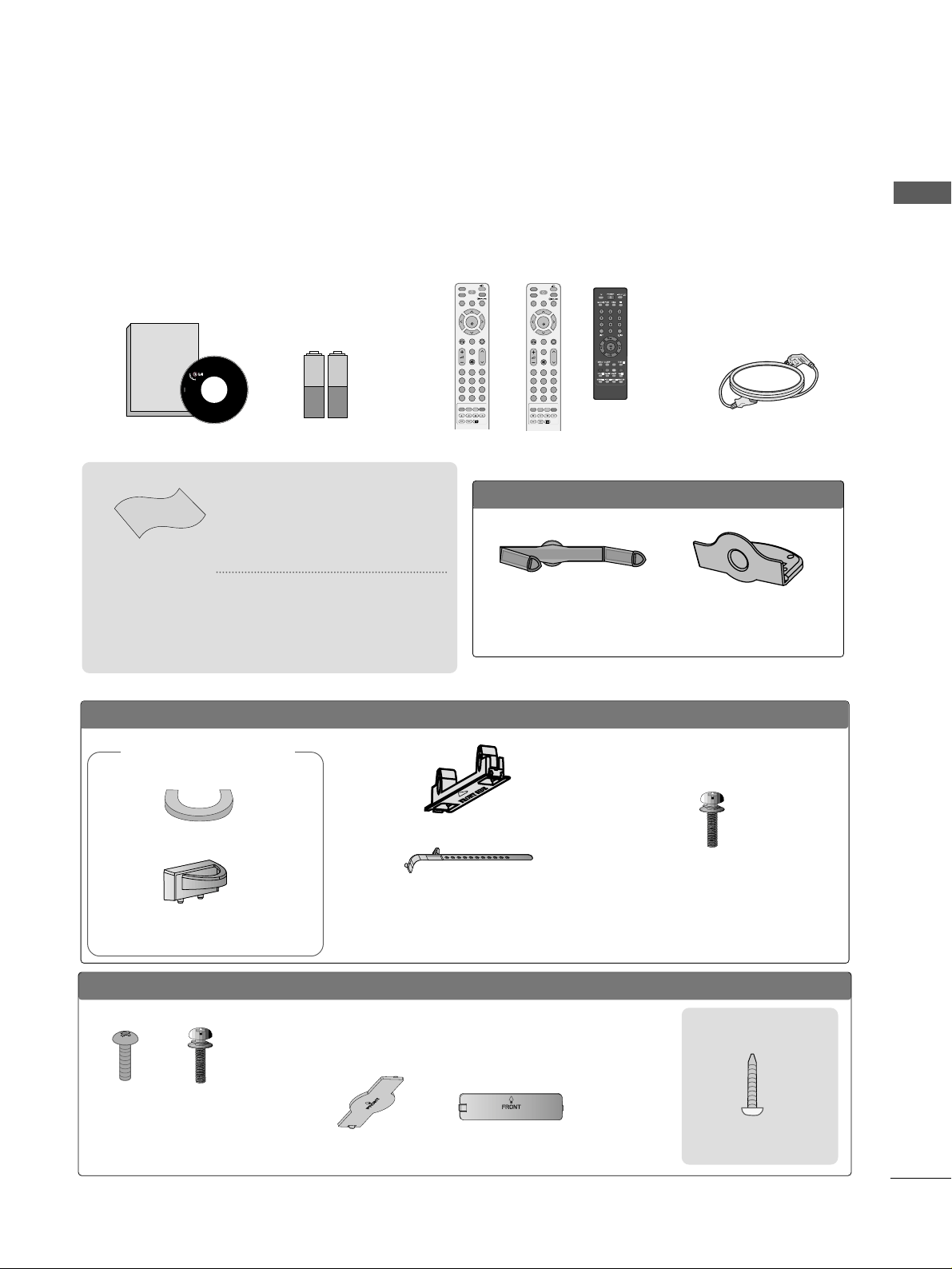
ACCESSORIES
Ensure that the following accessories are included with your TV. If an accessory is missing, please contact the
dealer where you purchased the product.
Owner's
Manual
Owner’s manual
Owner’s Manual Batteries Power Cord
Polishing Cloth
Polishing cloth for use
on the screen
This feature is not
available
for all models.
*
Lightly wipe any stains or
fingerprints on the surface
of the TV with the polishing
cloth.
Do not use excessive force.
This may cause scratching or
discolouration.
LLCCDD TTVV mmooddeellss
Bolts for stand assembly
(Refer to p.9)
(Only 37/42LG5
***
,
26/32/37/42LG3
***
)
x 4 x 4
protection cover
PPLLAASSMMAA TTVV mmooddeellss
(
only
42/50PG1
***
)
Cable Holder
(42PG1
***
, 42PG2
***
:1EA
,
50PG1
***
, 50PG2
***
: 2EA
)
Bolts for stand assembly
(Refer to P.10)
(42PG1
***
, 42 PG 2
***
:4EA
)
protection cover
(only 42/50PG2
***
)
Cable Management Clip
(Only 26/32/42LG3
***
,
42L G5
***
)
Screw for stand fixing
(Refer to P. 10)
ACCESSORIES
or
MUTE
PIP
AV MODE
FAV
TV
INPUT
STB
POWER
Q. MENU
MENU
OK
123
456
7809
LIST
Q.VIEW
DVD
TIME
SIZE
UPDATE
REVEAL
INDEX
HOLD TEXT
RETURN
P
MUTE
PIP
AV MODE
FAV
RATIO
INPUT
SOUND
POWER
Q. MENU
MENU
OK
123
456
7809
LIST
Q.VIEW
PICTURE
TIME
SIZE
UPDATE
REVEAL
INDEX
HOLD TEXT
RETURN
P
RATIO
Remote Control
or or
OOnnllyy 2222LLGG33
******
Cable Management Clip Protection Cover
Page 4

Watching PIP(Picture-in-Picture) .............................59
Picture Size (Aspect Ratio)Control.........................60
Preset Picture Settings
- Picture Mode-Preset............................................62
- Auto Colour Tone Control(Cool/Medium/Warm)
63
Manual Picture Adjustment
- Picture Mode-User Option................................64
- Colour Tone - User Option...............................65
-
Picture Improvement Technology
...................66
Advanced - Gamma......................................................67
Advanced - Film Mode ................................................68
Advanced - Black(Darkness) Level...........................69
Advanced - Eye Care ...................................................70
Picture Reset..................................................................71
Image Sticking Minimization(ISM) Method...........72
Power Saving Picture Mode .......................................73
Power Indicator..............................................................73
Factory Reset.................................................................74
Remote Control Key Functions..................................38
Turning on the TV....................................................... 44
Programme Selection ................................................. 44
Volume Adjustment......................................................44
Quick Menu .................................................................. 45
On Screen Menus Selection and Adjustment ......46
PICTURE CONTROL
WATCHING TV / PROGRAMME CONTROL
AACCCCEESSSSOORRIIEESS
.....................................................1
2
CONTENTS
CONTENTS
PREPARATION
Front Panel Controls................................................... 4
Back Panel Information .............................................. 6
Stand Installation ........................................................ 9
Please set it up carefully so the product
does not fall over.
. . . . . . . . . . . . . . . . . . . . . . . . .11
Back Cover for Wire Arrangement......................... 12
Swivel Stand ............................................................... 15
Positioning your display............................................15
Location........................................................................15
Kensington Security System ...................................15
Desktop Pedestal Installation................................. 16
Wall Mount: Horizontal installation....................... 16
Not using the desk-type stand................................17
Antenna Connection................................................. 18
PREPARATION
EXTERNAL EQUIPMENT SETUP
HD Receiver Setup .......................................................19
DVD Setup.................................................................... 22
VCR Setup..................................................................... 25
Headphone SETUP ......................................................28
Other A/V Source Setup .......................................... 29
External Stereo Setup ................................................ 30
AV Output Setup ........................................................ 30
PC Setup .........................................................................31
- Screen Setup for PC Mode................................34
Auto Programme Tuning............................................ 47
Manual Programme Tuning ....................................... 48
Fine Tuning .....................................................................49
Assigning a Station Name..........................................50
Booster............................................................................51
Programme Edit ........................................................... 52
Favourite Programme.................................................. 53
Selecting the Programme List.................................. 54
.................................................................. 55
Key lock.......................................................................... 57
AV Mode.........................................................................58
Page 5

SOUND & LANGUAGE CONTROL
Auto Volume Leveler ....................................................75
Preset Sound Settings - Sound Mode ....................76
Sound Setting Adjustment - User Mode ...............77
Balance ............................................................................78
TV Speakers On/Off Setup .......................................79
Selecting Audio Out ....................................................80
I/II
- Stereo/Dual Reception....................................... 81
- NICAM Reception ....................................................... 82
- Speaker Sound Output Selection.................... 82
On-Screen Menu Language Selection
...................... 83
3
CONTENTS
APPENDIX
Troubleshooting............................................................91
Maintenance .................................................................93
Product Specifications................................................94
Programming the Remote Control ........................ 97
IR Codes ....................................................................... 99
External Control Through RS-232C ................... 101
TIME SETTING
Clock Setup .....................................................................84
Auto On/Off Timer Setting .........................................85
Sleep Timer Setting .......................................................86
Auto Shut-off Setting...................................................87
TELETEXT
Switch On/Off .............................................................88
SIMPLE Text ...................................................................88
TOP Text.........................................................................89
FASTEXT.........................................................................89
Special Teletext Functions..........................................90
Page 6

4
FRONT PANEL CONTROLS
PREPARATION
PREPARATION
■
This is a simplified representation of the front panel. Image shown may differ from your TV.
■
If your product has a protection film attached, remove the film and then wipe the product with a polishing
cloth.
PLASMA TV Models: 42/50PG1
***
PROGRAMME
VOLUME
MENU
OK
INPUT
MENU OK INPUT POWER
VOLUME PROGRAMME
Remote Control Sensor
Remote Control Sensor
Power/Standby Indicator
• illuminates red in standby mode.
• illuminates green when the TV is
switched on.
POWER
Power/Standby Indicator
• illuminates red in standby mode.
• illuminates green when the TV is
switched on.
OK
MENU
INPUT
OK
MENU
INPUT
PLASMA TV Models: 42/50PG2
***
INPUT
MENU
OK
- +
P
INPUT
MENU
OK
- +
P
Page 7

5
PREPARATION
Intelligent Sensor
Adjusts picture according to the surrounding
conditions (
Only
37/42/47/52LG5
***
)
POWER
Remote Control Sensor
Power/Standby Indicator
• illuminates red in standby mode.
• illuminates blue when the TV is switched on.
Note:
You can adjust
PPoowweerr IInnddiiccaattoorr
in
the OPTION menu.
PROGRAMME
VOLUME
OK
MENU
INPUT
PROGRAMMEVOLUME
MENU
OK
INPUT
LCD TV Models : 22LG3
***
LCD TV Models :
26/32/37/42/47LG3
***
, 37/42/47/52LG5
***
POWER
Remote Control Sensor
Power/Standby Indicator
• illuminates red in standby mode.
• illuminates blue when the TV is switched on.
INPUT MENU PRVOLOK
P
+
-
OK
MENU
INPUT
Page 8
6
PREPARATION
PREPARATION
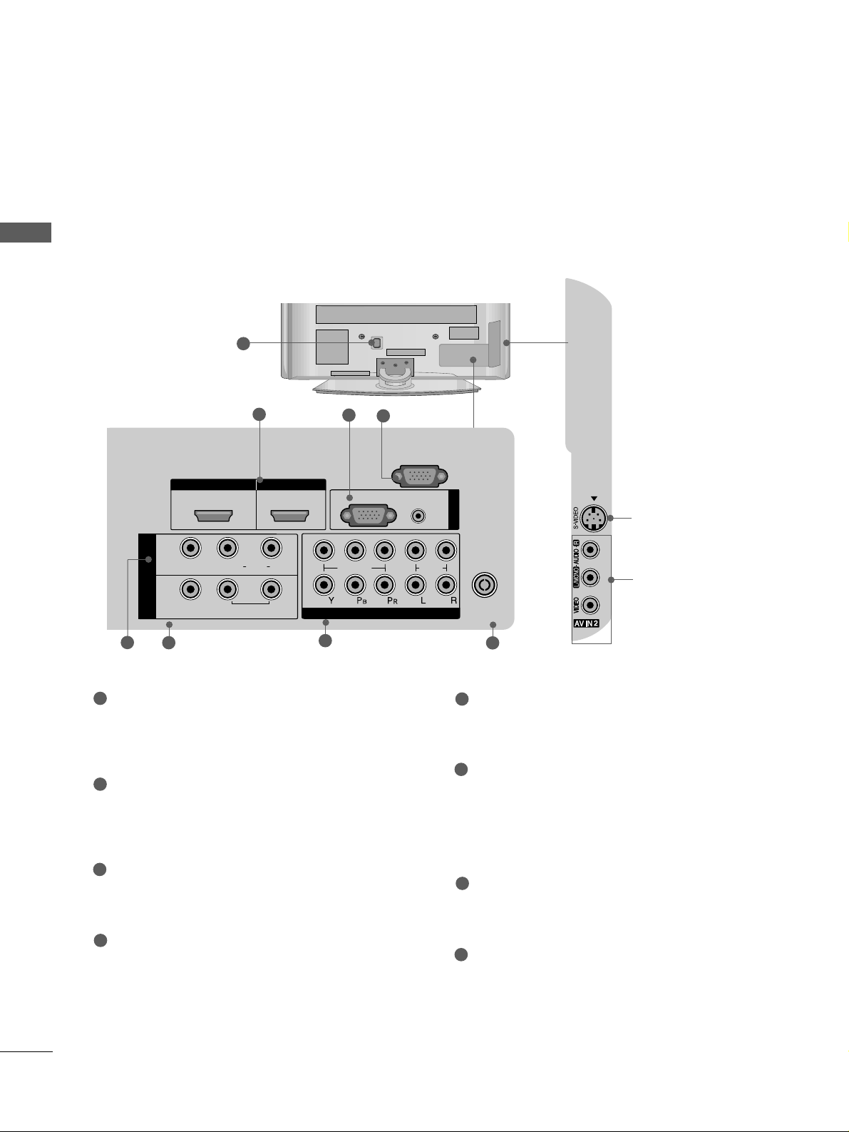
BACK PANEL INFORMATION
A
Image shown may differ from your TV.
PLASMA TV Models
1
AUDIO
VIDEO
VARIABLE AUDIO OUT
S-Video Input
Connect S-Video out from
an S-VIDEO device.
Audio/Video Input
Connect audio/video output from an external
device to these jacks.
2
6
5
7
8
3
4
Power Cord Socket
This TV operates on an AC power. The voltage is
indicated on the Specifications page. Never
attempt to operate the TV on DC power.
HDMI Input
Connect a HDMI signal to HDMI IN.
Or DVI(VIDEO)signal to HDMI/DVI port with DVI
to HDMI cable.
RGB/Audio Input
Connect the monitor output from a PC to the
appropriate input port.
RS-232C Input
(CONTROL) Port
Connect the serial port of the control devices to
the RS-232C jack.
(This feature is not available for all models.)
Audio/Video Input (AV IN 1)
Connect audio/video output from an external
device to these jacks.
AV Output
Connect second TV or monitor to the AV OUT
socket on the
TV.
Variable Audio Output
Connect an external amplifier or add a subwoofer
to your surround sound system.
Component Input
Connect a component video/audio device to
these jacks.
Antenna Input
Connect RF antenna to this jack.
1
2
3
4
5
6
7
8
IN 1
VIDEO
AV
OUT
HDMI IN HDMI/DVI IN
12
R
AUDIO
L( MONO)
VARIABLE AUDIO OUT
2
1
RGB
VIDEO
COMPONENT IN
(PC)
RS-232C IN
(CONTROL)
AUDIO
(RGB/DVI)
AUDIO
RGB IN
ANTENNA
IN
Page 9
7
PREPARATION
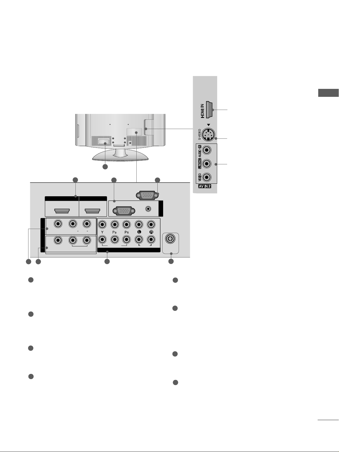
LCD TV Models
1
3
S-Video Input
Connect S-Video out from
an S-VIDEO device.
Audio/Video Input
Connect audio/video output from an external
device to these jacks.
HDMI Input
Connect a HDMI signal to
HDMI IN.
(This feature is
not available for all models.)
HDMI IN
HDMI/DVI IN
RGB IN
COMPONENT IN
AUDIO
VIDEO
VARIABLE
AUDIO OUT
3 4
2
7
5
Power Cord Socket
This TV operates on an AC power. The voltage is
indicated on the Specifications page. Never
attempt to operate the TV on DC power.
HDMI Input
Connect a HDMI signal to HDMI IN.
Or DVI(VIDEO)signal to HDMI/DVI port with DVI
to HDMI cable.
RGB/Audio Input
Connect the monitor output from a PC to the
appropriate input port.
RS-232C Input
(CONTROL) Port
Connect the serial port of the control devices to
the RS-232C jack.
(This feature is not available for all models.)
Audio/Video Input (AV IN 1)
Connect audio/video output from an external
device to these jacks.
AV Output
Connect second TV or monitor to the AV OUT
socket on the
TV.
Variable Audio Output
Connect an external amplifier or add a subwoofer
to your surround sound system.
Component Input
Connect a component video/audio device to
these jacks.
Antenna Input
Connect RF antenna to this jack.
1
2
3
4
5
6
7
8
6
8
HDMI/DVI IN
1
IN 1
VIDEO
AV
OUT
L( MONO)
VARIABLE
AUDIO OUT
AUDIO
HDMI IN
2
R
RGB
VIDEO
COMPONENT IN
(PC)
RS-232C IN
(CONTROL)
AUDIO
(RGB/DVI)
AUDIO
2
1
RGB IN
ANTENNA
IN
Page 10
8
PREPARATION
PREPARATION
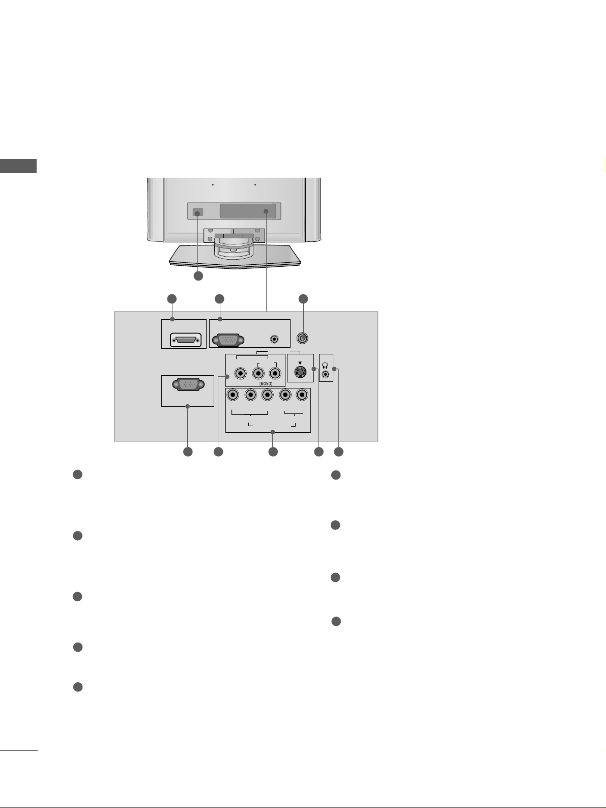
Only 22LG3
***
1
RGB (PC) IN
S-VIDEO
AV IN
VIDEO
L
R
AUDIO
Y
PBPRLR
VIDEO
COMPONENT IN
AUDIO
HDMI/DVI IN
AUDIO
(RGB/DVI) IN
H/P
ANTENNA IN
RS-232C IN
(CONTROL&SERVICE)
Power Cord Socket
This TV operates on an AC power. The voltage is
indicated on the Specifications page. Never
attempt to operate the TV on DC power.
HDMI Input
Connect a HDMI signal to HDMI IN.
Or DVI(VIDEO)signal to HDMI/DVI port with DVI
to HDMI cable.
RGB/Audio Input
Connect the monitor output from a PC to the
appropriate input port.
Antenna Input
Connect RF antenna to this jack.
RS-232C Input
(CONTROL&SERVICE) Por t
Connect the serial port of the control devices to
the RS-232C jack.
Audio/Video Input
Connect audio/video output from an external
device to these jacks.
Component Input
Connect a component video/audio device to
these jacks.
S-Video Input
Connect S-Video out from an S-VIDEO device.
Headphone Input
1
2
3
4
5
6
7
8
9
2
6
43
5 7 8 9
BACK PANEL INFORMATION
A
Image shown may differ from your TV.
Page 11
9
PREPARATION
■
Image shown may differ from your TV
■
When assembling the desk type stand, check whether the bolt is fully tightened. (If not tightened fully, thep
roduct can tilt forward after the product installation.) If you tighten the bolt with excessive force, the boltcan
deviate from abrasion of the tightening part of the bolt.
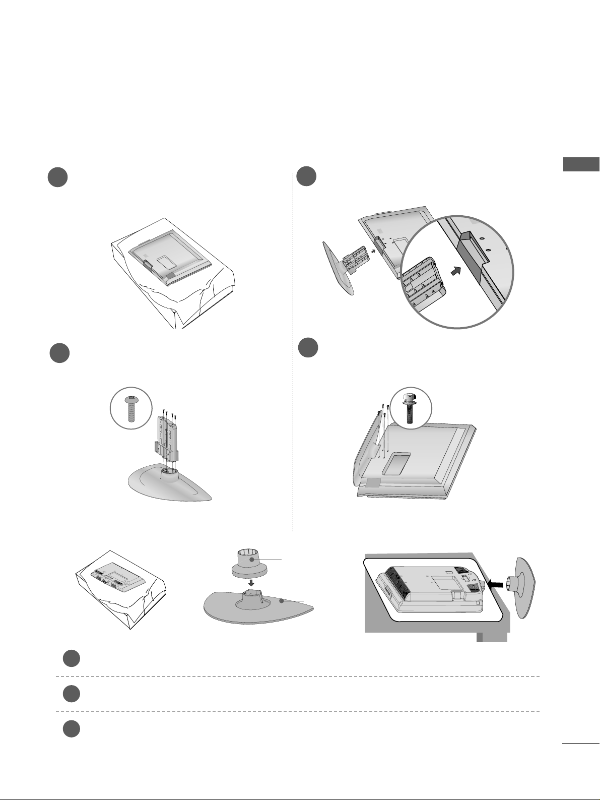
1
3
4
Carefully place the TV screen side down on a
cushioned surface to protect the screen from
damage.
2
Assemble the parts of the
SS tt aa nndd BBoodd yy
with
the
CCoovvee rr BB aa ssee
of the TV.
Assemble the TV as shown.
Fix the 4 bolts securely using the holes in the
back of the TV.
STAND INSTALLATION
LCD TV Models:
26/32/37/42LG3
***,
37/42LG5
***
(Only 22LG3
***
)
Carefully place the TV screen side down on a cushioned surface to protect the screen from damage.
Assemble the parts of the
SSTTAANNDD BBOODDYY
with
CCOOVVEERR BBAASS EE
of the TV. Insert the
SSTTAANNDD BBOODDYY
into a
CCOOVVEERR BBAASS EE
until clicking sound.
Assemble the TV as shown.
1
2
3
Stand Body
Cover Base
Page 12
10
PREPARATION
PREPARATION
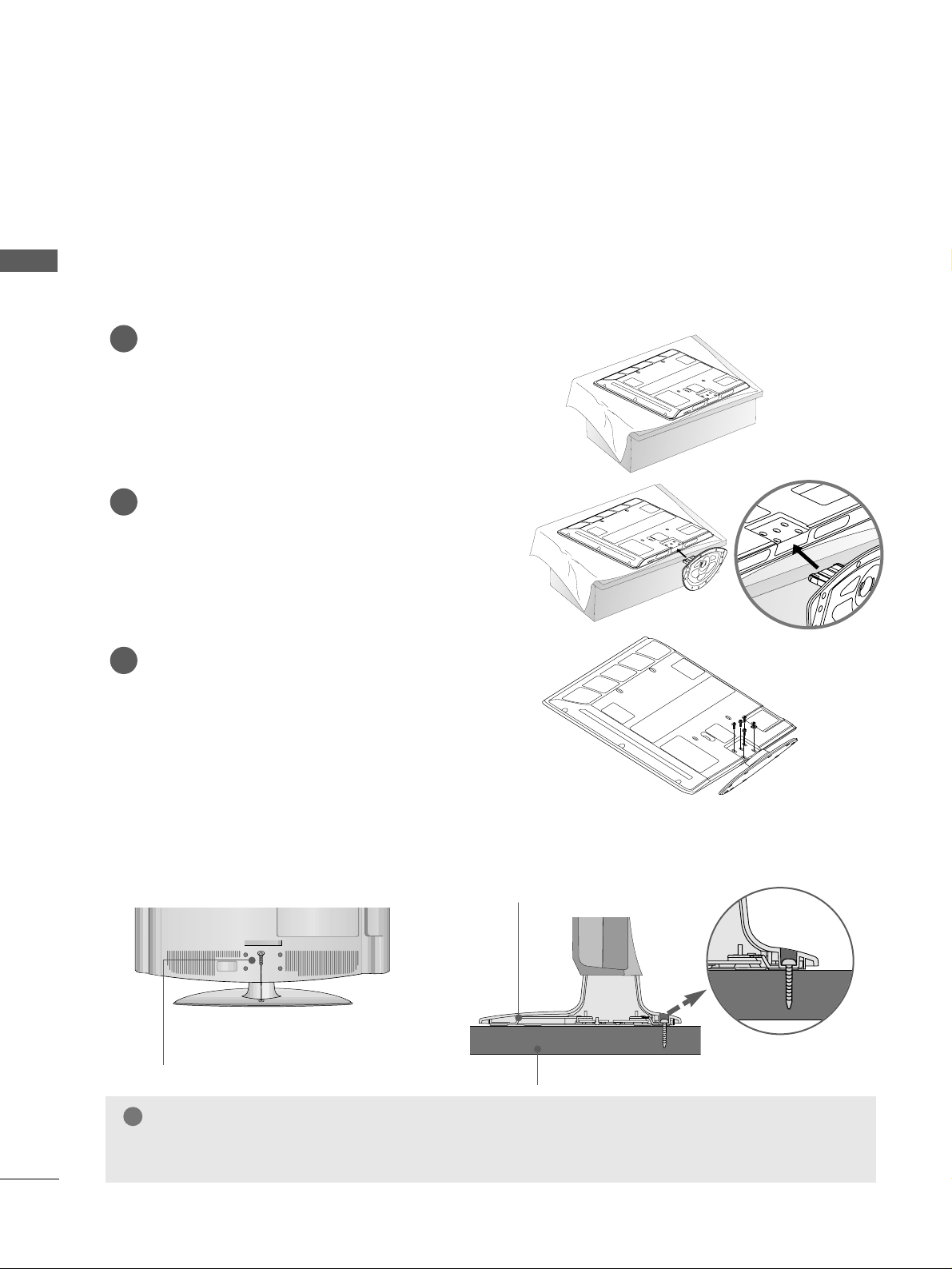
STAND INSTALLATION
PLASMA TV Models (Only 42PG1
***
, 42PG2
***
)
■
Image shown may differ from your TV
■
When assembling the desk type stand, check whether the bolt is fully tightened. (If not tightened fully, thep
roduct can tilt forward after the product installation.) If you tighten the bolt with excessive force, the boltcan
deviate from abrasion of the tightening part of the bolt.
Carefully place the TV screen side down on a
cushioned surface to protect the screen from
damage.
Assemble the TV as shown.
Fix the 4 bolts securely using the holes in the
back of the TV.
1
2
3
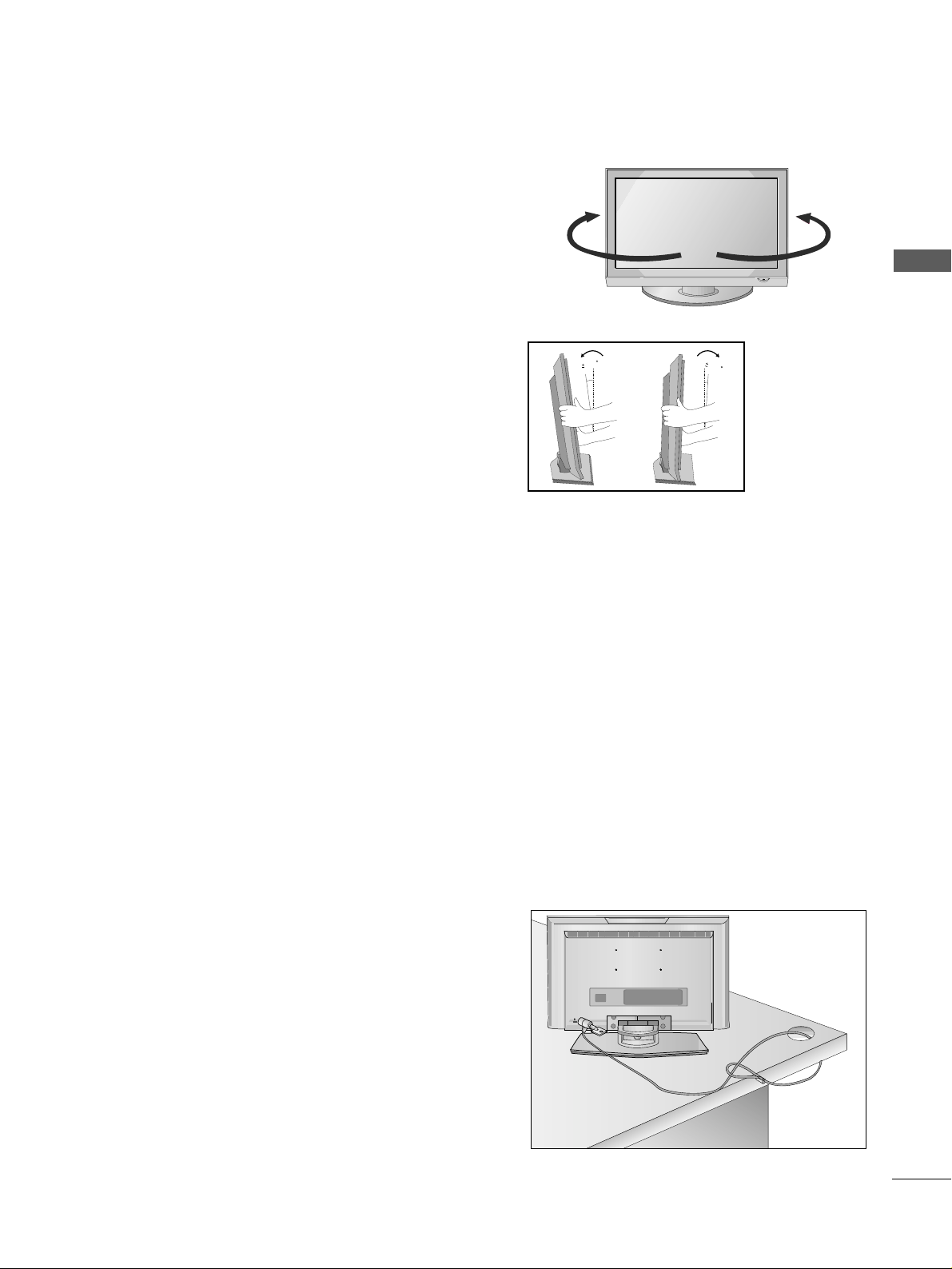
Attaching the TV to a desk (Only 26/32/42LG3
***
,42LG5
***
)
The TV must be attached to desk so it cannot be pulled in a forward/backward direction, potentially causing
injury or damaging the product. Use only an attached screw.
1-Screw
(provided as parts of the product)
Desk
Stand
WARNING
!
GG
To prevent TV from falling over, the TV should be securely attached to the floor/wall per installation
instructions. Tipping, shaking, or rocking the machine may cause injury.
Page 13
11
PREPARATION
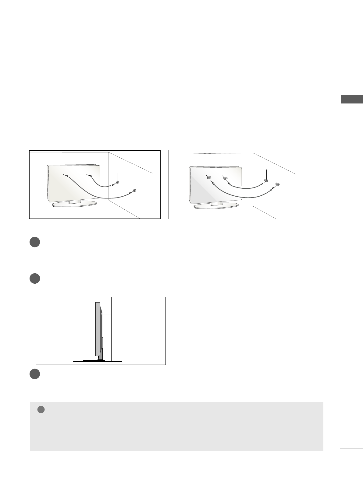
PLEASE SET IT UP CAREFULLY SO THE PRODUCT DOES NOT
FALL OVER.
A
You should purchase necessary components to fix the TV to the wall on the market.
A
Position the TV close to the wall to avoid the possibility of it falling when pushed.
A
The instructions shown below are a safer way to
set
up the TV, which is to fix it to the wall, avoiding the
possibility of it falling forwards if pulled. This will prevent the TV from falling forward and causing injury.
This will also prevent the TV from damage. Ensure that children do not climb or hang from the TV.
NOTE
!
G
When moving the TV undo the cords first.
G
Use a platform or cabinet string and large enough to support the size and weight of the TV.
G
To use the TV safely make sure that the height of the bracket on the wall and on the TV is the same.
3
1
2
Use the eye-bolts or TV brackets/bolts to fix the product to the wall as shown in the picture.
(If your TV has bolts in the eyebolts, loosen then bolts.)
* Insert the eye-bolts or TV brackets/bolts and tighten them securely in the upper holes.
Secure the wall brackets with bolts to the wall.
Ensure that both brackets are even.
3
Use a strong cord to secure the TV.
Secure the cord in such a way that it becomes taught when the TV is in position.
2
1
2
1
Page 14
12
PREPARATION
PREPARATION
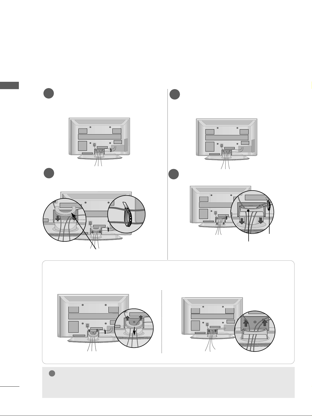
BACK COVER FOR WIRE ARRANGEMENT
■
Here shown may be somewhat different from your TV.
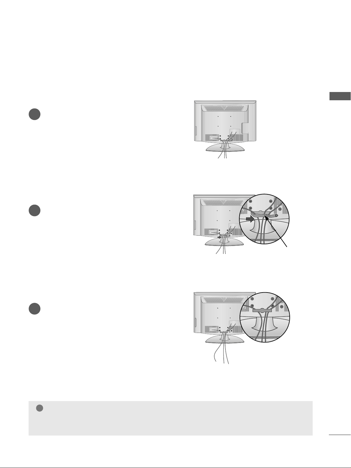
PLASMA TV Models
Connect the cables as necessary.
To connect additional equipment, see the
EExxttee rrnnaall EEqq uu iippmm eenntt SSeettuupp
section.
1
Install the
CCAABBLLEE MMAANNAAGGEEMMEENNTT CCLLIIPP
as shown.
2
Install the
CCAABBLLEE MMAANNAAGGEEMMEENNTT CCLLIIPP
as shown.
2
Hold the
CCAABBLLEE MMAANNAAGGEEMMEENNTT CCLLIIPP
with both hands and pull it upward.
NOTE
!
GG
Do not use the CABLE MANAGEMENT CLIP to lift the TV.
- If the TV is dropped, you may be injured or the TV may be damaged.
How to remove the cable management clip
CABLE MANAGEMENT CLIP
* For the 42PG1
***
model, press the center of the CABLE MANAGEMENT CLIP and then lift up it.
Fix the
CCaabbllee
HHoollddee rr
as shown and
bundle the cables.
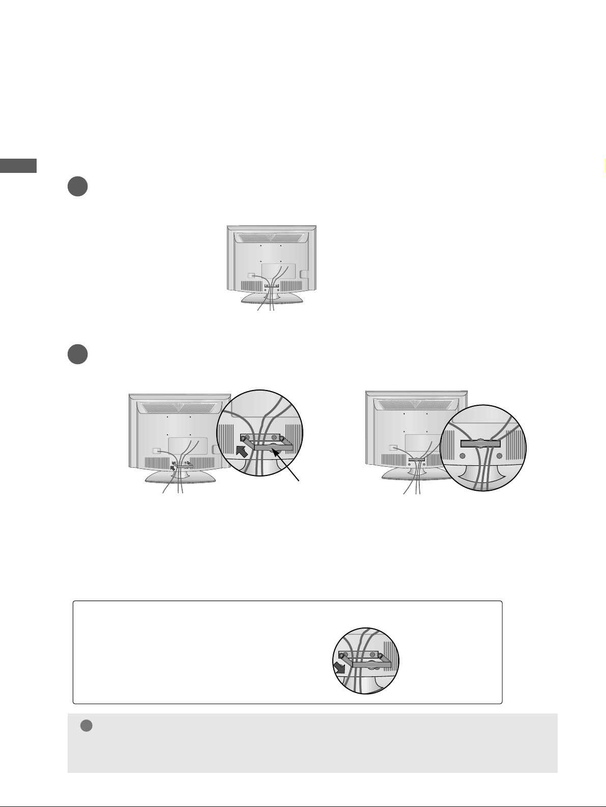
Connect the cables as necessary.
To connect additional equipment, see the
EExxttee rrnnaall EEqquu iippmm eenntt SSeettuupp
section.
1
42/50PG2
***
42/50PG1
***
CABLE MANAGEMENT CLIP
Fix the
CCaa bbllee HHoo llddeerr
as
shown and bundle the
cables.
Page 15
13
PREPARATION
BACK COVER FOR WIRE ARRANGEMENT
LCD TV Models
Connect the cables as necessary.
To connect additional equipment, see the
External Equipment Setup section of the
manual.
1
Open the
CCAABBLLEE MMAANNAAGGEEMMEENNTT CCLLIIPP
as
shown and manage the cables.
2
CABLE MANAGEMENT CLIP
Fit the
CCAABBLLEE MMAANNAAGGEEMMEENNTT CCLLIIPP
as
shown.
3
NOTE
!
GG
Do not use the CABLE MANAGEMENT CLIP to lift the TV.
- If the TV is dropped, you may be injured or the TV may be damaged.
Page 16
14
PREPARATION
PREPARATION
PREPARATION
BACK COVER FOR WIRE ARRANGEMENT
Only 22LG3
***
Connect the cables as necessary.
To connect additional equipment, see the External Equipment Setup section of the manual.
1
Install the
CCAABBLLEE MMAANNAAGGEEMMEENNTT CCLLIIPP
as shown.
2
CABLE MANAGEMENT CLIP
NOTE
!
GG
Do not use the CABLE MANAGEMENT CLIP to lift the TV.
- If the TV is dropped, you may be injured or the TV may be damaged.
How to remove the CABLE MANAGEMENT CLIP
GG
Hold the CABLE MANAGEMENT CLIP with both
hands and pull it backward.
Page 17
15
PREPARATION
SWIVEL STAND
This feature is not available for all models.
After installing the TV, you can adjust the TV manually
to the left or right direction by 20 degrees to suit your
viewing position.
POSITIONING YOUR
DISPLAY
(Only 22LG3
***
)
■
Image shown may differ from your TV.
■
Adjust the position of the panel in various ways for
maximum comfort.
• Tilt range
12
1.5
3
1.5
LOCATION
(Only 22LG3
***
)
Position your TV so that no bright light or sunlight falls directly onto the screen. Care should be taken not to
expose the tv to any unnecessary vibration, moisture, dust or heat. Also ensure that the TV is placed in a position
to allow a free flow of air. Do not cover the ventilation openings on the back cover.
If you intend to mount the TV to a wall, attach VESA standard mounting interface (optional parts) to the back of
the TV.
When you install the TV to use the wall mounting bracket (optional parts), fix it carefully so as not to drop.
KENSINGTON SECURITY SYSTEM
(Only 22LG3
***
)
The TV is equipped with a Kensington Security System connector on the back panel. Connect the Kensington
Security System cable as shown below.
For the detailed installation and use of the Kensington Security System, refer to the user’s guide provided with
the Kensington Security System.
For further information, contact http://www.kensington.com, the internet homepage of the Kensington
company. Kensington sells security systems for expensive electronic equipment such as notebook PCs and LCD
projectors.
NOTE
- The Kensington Security System is an optional accessory.
NOTES
a. If the TV feels cold to the touch, there may be a small “flicker”
when when it is turned on.
This is normal, there is nothing wrong with TV.
b. Some minute dot defects may be visible on the screen, appear-
ing as tiny red, green, or blue spots. However, they have no
adverse effect on the monitor's performance.
c. Avoid touching the LCD screen or holding your finger(s)
against it for long periods of time.
Doing so may produce some temporary distortion effects on
the screen.
Page 18

16
PREPARATION
PREPARATION
PREPARATION
■
The TV can be installed in various ways such as on a wall, or on a desktop etc.
■
The TV is designed to be mounted horizontally.
DESKTOP PEDESTAL INSTALLATION
For adequate ventilation allow a clearance of 4” (10cm) all around the TV .
4 inches
4 inches
4 inches
4 inches
Power Supply
Circuit breaker
EARTHING
Ensure that you connect the earth wire to prevent possible electric shock. If grounding methods are not
possible, have a qualified electrician install a separate circuit breaker.
Do not try to earth the TV by connecting it to telephone wires, lightening rods or gas pipes.
4 inches
4 inches
4 inches
4 inches
4 inches
WALL MOUNT: HORIZONTAL INSTALLATION
For adequate ventilation allow a clearance of 4” (10cm) all around the TV. We recommend that you use a wall
mounting bracket of LG brand when mounting the TV to a wall.
Page 19
17
PREPARATION
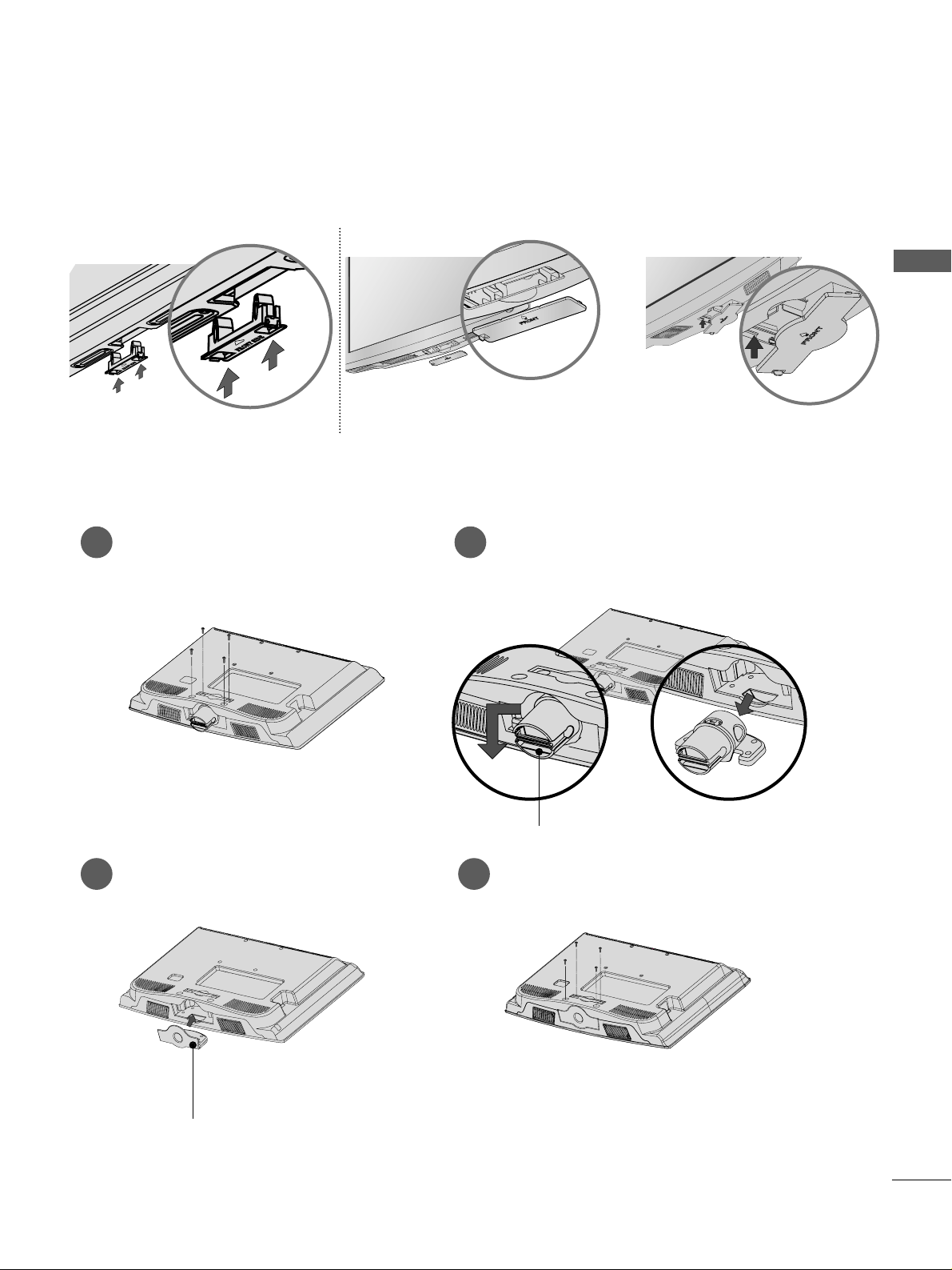
When installing the wall-mounted unit, use the protection cover for desk-type stand installation.
NOT USING THE DESK-TYPE STAND
Plasma TV Models
LCD TV Model
or
Only 22LG3
***
Loose the bolts from TV.
1
Bend the
HHIINNGGEE BBOO DDYY
and pull it
backward.
2
Insert the
PPRROOTTEECCTTIIOONN CCOOVV EERR
into
the TV.
3
Fix the 4 bolts securely using the holes in
the back of the TV.
4
PPRROOTTEECCTTIIOONN CCOO VVEERR
HHIINNGGEE BBOO DDYY
Insert the PROTECTION COVER into
the TV until clicking sound.
Page 20

RGB IN
ANTENNA
IN
18
PREPARATION
PREPARATION
PREPARATION
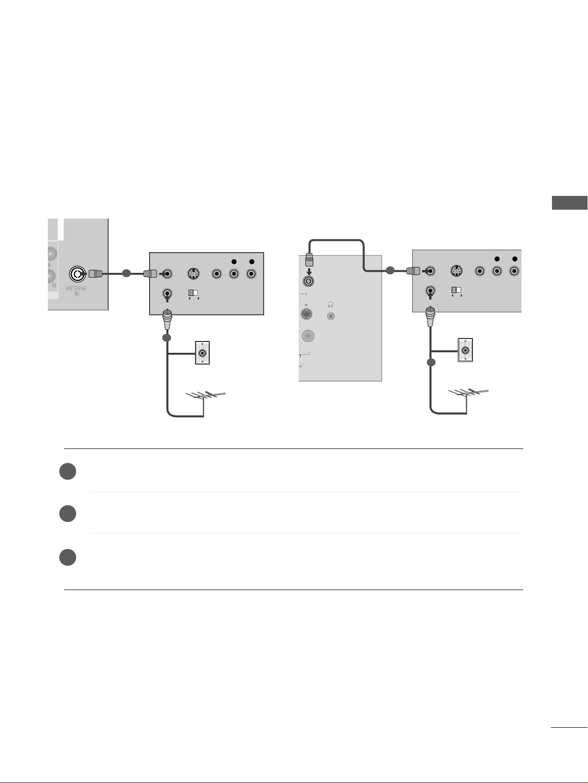
ANTENNA CONNECTION
■
For optimum picture quality, adjust antenna direction.
■
An antenna cable and converter are not supplied.
■
To prevent damage do not connect to the mains outlet until all connections are made between the devices.
RGB IN
ANTENNA
IN
Multi-family Dwellings/Apartments
(Connect to wall antenna socket)
Single-family Dwellings /Houses
(Connect to wall jack for outdoor antenna)
Outdoor
Antenna
Wall
Antenna
Socket
RF Coaxial Wire (75 ohm)
Antenna
UHF
Signal
Amplifier
VHF
■
In poor signal areas, to achieve better picture quality it may be necessary to install a signal amplifier to the
antenna as shown above.
■
If signal needs to be split for two TVs,use an antenna signal splitter for connection.
Page 21
19
EXTERNAL EQUIPMENT SETUP
EXTERNAL EQUIPMENT SETUP
■
To avoid damaging any equipment, never plug in any power cords until you have finished connecting all equipment.
■
This section on EXTERNAL EQUIPMENT SETUP mainly uses diagrams for the Plasma TV models.
■
Image shown may differ from your TV.
L/ MONO
VIDEO
VARIABLE AUDIO OUT
HDMI/DVI IN
1
2
COMPONENT IN
VIDEO
AUDIO
1 2
HD RECEIVER SETUP
Connecting with a component cable
Connect the video outputs (Y, PB
, PR
)
of the digital TV
top box to the
CCOOMMPPOONNEENNTT IINN VV IIDD EEOO
jacks on the
TV.
Connect the audio output of the digital set-top box to
the
CCOOMMPPOONNEENNTT IINN AAUU DDIIOO
jacks on the TV.
Turn on the digital set-top box.
(
Refer to the owner’s manual for the digital set-top box.
)
Select
CCoo mm ppoonnee nn tt11
input source using the
IINNPP UUTT
button on the remote control.
If connected to
CCOOMMPPOONNEENNTT IINN22
, select
CCoo mm ppoonneenn tt22
input source(Except 22LG3
***
).
2
3
4
1
Signal
480i/576i
480p/576p
720p/1080i
10 8 0 p
Component
Yes
Yes
Yes
Yes
(Only 50Hz, 60Hz)
HDMI1/DVI, HDMI2(Except 22LG3
***
),
HDMI3(Only 37/42/47/52LG5
***
)
No
Yes
Yes
Yes
(24Hz, 30Hz, 50Hz, 60Hz)
(22LG3
***
- Only 50Hz, 60Hz)
Y
PBPR
LR
VIDEO
COMPONENT IN
AUDIO
1 2
Only 22LG3
***
Page 22
L/MONO
R
AUDIOAUDIO
VIDEOVIDEO
IN 1
OUT
VARIABLE AUDIO OUT
L/ MONO
R
AUDIO
VIDEO
VARIABLE AUDIO OUT
HDMI IN HDMI DVI IN
HDMI/DVI IN
1
HDMI IN HDMI DVI IN
HDMI IN HDMI IN HDMI/DVI IN HDMI/DVI IN
1 2
1
20
EXTERNAL EQUIPMENT SETUP
EXTERNAL EQUIPMENT SETUP
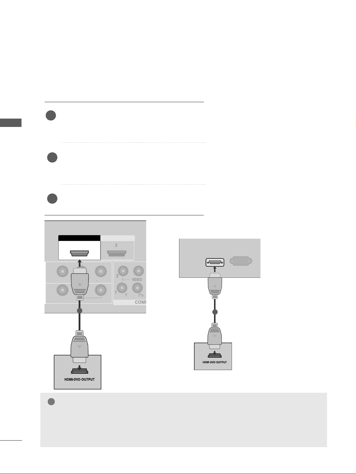
Connecting a set-top box with a HDMI cable
Connect the HDMI output of the digital set-top box to
the
HHDDMMII//DDVVII IINN 11,, HH DDMMII IINN 22
(Except 22LG3***)
or
HHDDMMII IINN 33
(
Only 37/
42/47/52LG5
***
) jack on the TV.
Select
HHDD MMII11//DD VVII,, HHDDMM II22
(Except 22LG3***) or
HHDD MMII33
(
Only 37/
42/47/52LG5
***
) input source using
the
IINNPP UUTT
button on the remote control.
Turn on the digital set-top box.
(
Refer to the owner’s manual for the digital set-top box.
)
2
3
1
GG
TV can receive the video and audio signal
simultaneously with using a HDMI cable.
GG
If the digital set-top box supports Auto HDMI
function, the output resolution of the source
device will be automatically TV to 1280x720p.
GG
If the digital set-top box player does not support Auto HDMI, you need to TV the output
resolution appropriately.
To get the best picture quality, adjust the
output resolution of the source device to
1280x720p (42 LG31F**,
37/42/47/52LG5
***
: 1920x1080i/1080p).
NOTE
!
HDMI/DVI IN
RGB
(PC) IN
1
Only 22LG3
***
Page 23
21
EXTERNAL EQUIPMENT SETUP
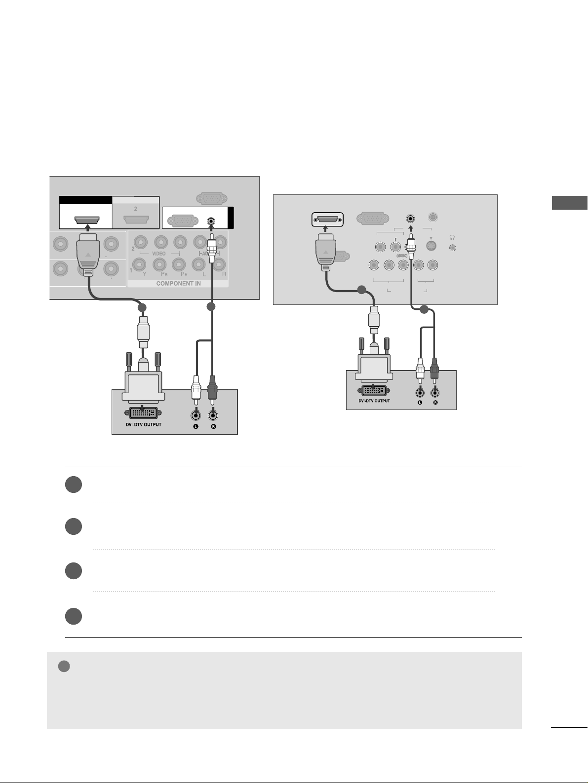
Connect the DVI output of the digital set-top box to the
HHDDMMII//DDVVII IINN 11
jack on the TV.
Connect the audio output of the digital set-top box to the
AAUU DDIIOO((RRGGBB//DDVVII))
jack on the TV.
Turn on the digital set-top box. (Refer to the owner’s manual for the digital set-top box.
)
Select
HHDDMMII11// DDVVII
input source using the
IINNPP UUTT
button on the remote control.
2
3
4
1
Connecting with a HDMI to DVI cable
GG
HDMI2(Except 22LG3***), HDMI3(
Only 37/
42/47/52LG5
***
) source does not support DVI source.
GG
If the Set-Top Box has a DVI output and no HDMI output, a separated audio connection is necessary.
GG
If the Set-Top Box does not support Auto DVI, you need to set the output resolution appropriately.
NOTE
!
L/L/MONOMONO
R
AUDIOAUDIO
VIDEOVIDEO
VARIABLE ARIABLE AUDIO OUTAUDIO OUT
HDMI IN HDMI DVI IN
HDMI/DVI IN HDMI/DVI IN
1
AUDIO
(RGB/DVI)
RGB
(PC)
RGB IN
RS-232C IN
(CONTROL)
1
2
S-VIDEO
AV IN
VIDEO
L
R
AUDIO
Y
PBPRLR
VIDEO
COMPONENT IN
AUDIO
HDMI/DVI IN
AUDIO
(RGB/DVI) IN
H/P
ANTENNA IN
RS-232C IN
(CONTROL&SERVICE)
RGB
(PC) IN
1
2
Only 22LG3
***
Page 24

1
2
COMPONENT IN
VIDEO
AUDIO
1 2
22
DVD SETUP
EXTERNAL EQUIPMENT SETUP
EXTERNAL EQUIPMENT SETUP
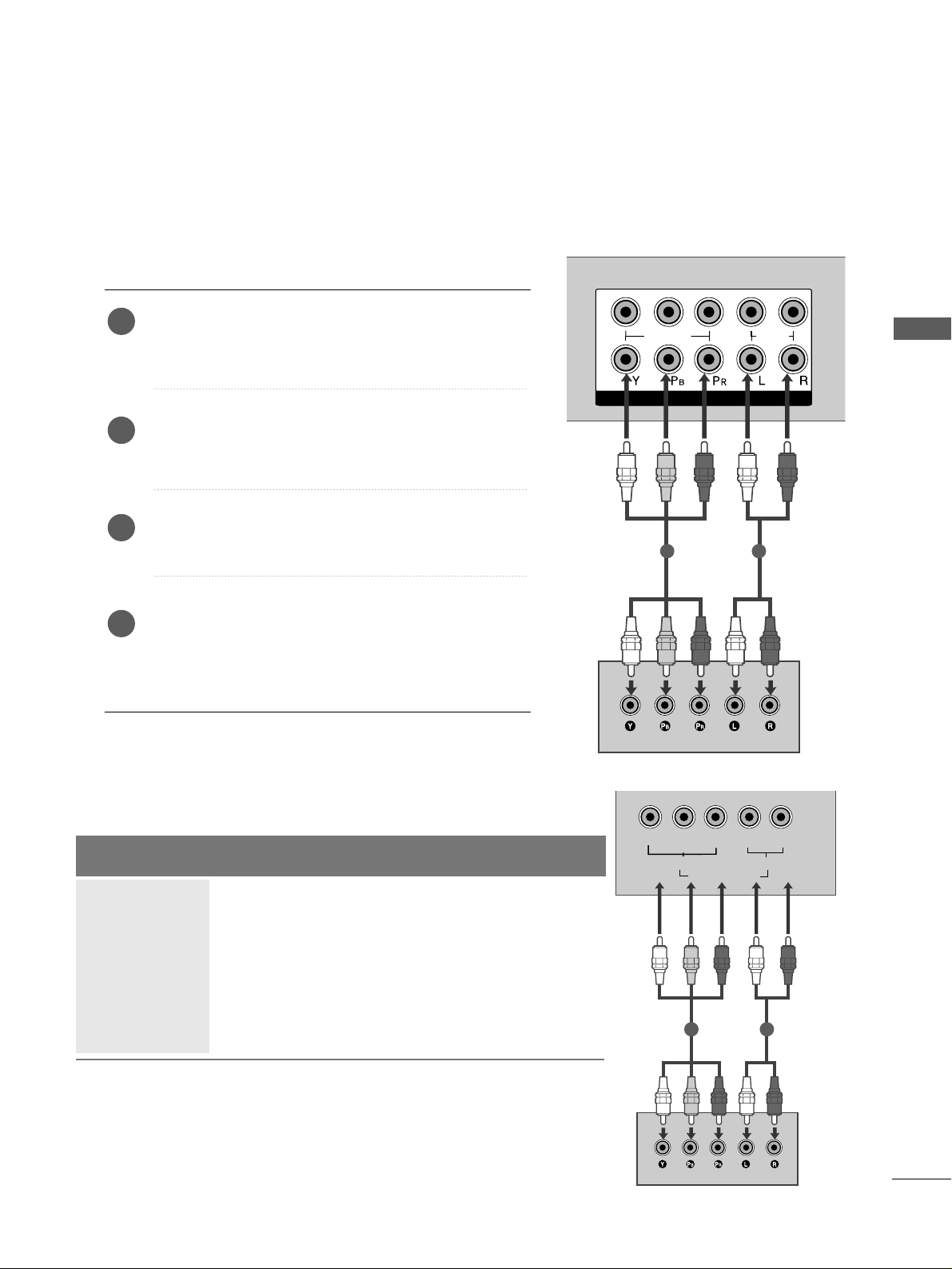
Connecting with a component cable
Component Input ports
To achieve better picture quality, connect a DVD player to
the component input ports as shown below.
Component ports on the TV
YPB PR
Video output ports
on DVD player
Y
Y
Y
Y
PB
B-Y
Cb
Pb
P
R
R-Y
Cr
Pr
Connect the video outputs (Y, PB
, PR
)
of the DVD to the
CCOOMMPPOONNEENNTT IINN VV IIDD EEOO
jacks on the TV.
Connect the audio outputs of the DVD to the
CCOOMMPPOONNEENNTT IINN AAUU DDIIOO
jacks on the TV.
Turn on the DVD player, insert a DVD.
Select
CCoomm ppoonnee nn tt11
input source using the
IINNPP UUTT
button
on the remote control.
If connected to
CCOOMMPPOONNEENNTT IINN22
, select
CCoo mm ppoonneenn tt 22
input source(Except 22LG3***).
Refer to the DVD player's manual for operating instructions.
2
3
4
5
1
Y
PBPR
LR
VIDEO
COMPONENT IN
AUDIO
1 2
Only 22LG3
***
Page 25

23
EXTERNAL EQUIPMENT SETUP
Connecting with a S-Video cable
Connect the S-VIDEO output of the DVD to the
SS -- VVIIDDEE OO
input on the TV.
Connect the audio outputs of the DVD to the
AAUUDDIIOO
input jacks on the TV.
Turn on the DVD player, insert a DVD.
Select
AAVV22
input source using the
IINNPP UUTT
button on
the remote control.
Refer to the DVD player's manual for operating
instructions.
2
3
4
5
1
AV IN 2
L R
S-VIDEOVIDEO
OUTPUT
SWITCH
ANT IN
ANT OUT
1
2
Only 22LG3
***
S-VIDEO
AV IN
VIDEO
L
R
AUDIO
Y
PB
PRLR
VIDEO
COMPONENT IN
AUDIO
H/P
L R
S-VIDEOVIDEO
OUTPUT
SWITCH
ANT IN
1
2
Page 26
24
EXTERNAL EQUIPMENT SETUP
EXTERNAL EQUIPMENT SETUP
HDMI IN HDMI DVI IN
HDMI IN HDMI IN HDMI/DVI IN HDMI/DVI IN
1 2
HDMI IN HDMI DVI IN
AV IN 2
L/ MONO
R
AUDIO
VIDEO
L/MONO
R
AUDIOAUDIO
VIDEOVIDEO
IN 1
OUT
VARIABLE AUDIO OUT
1
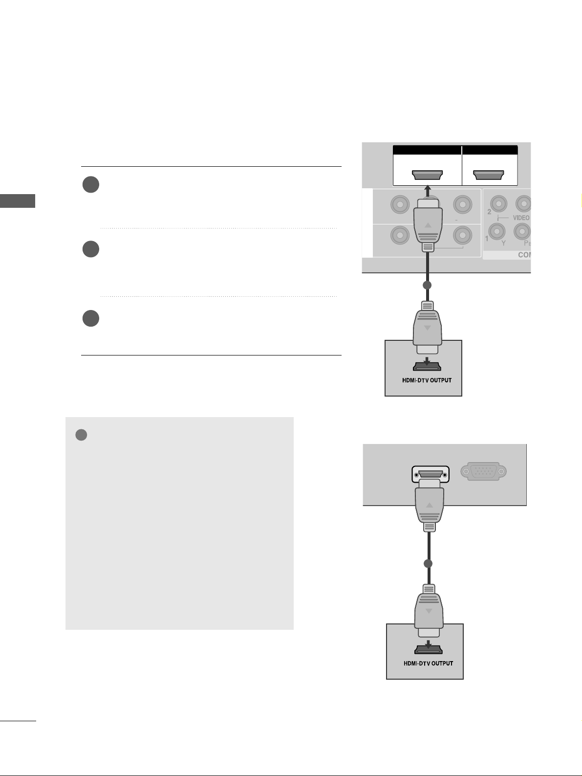
Connecting with a HDMI cable
Connect the HDMI output of the DVD to the
HHDDMMII//DDVVII IINN 11 ,, HHDDMMII IINN 22
(Except 22LG3***) or
HHDDMMII IINN 33
(
Only 37/
42/47/52LG5
***
) jack on the TV.
Select
HHDD MMII11//DD VVII,, HHDDMM II22
(Except 22LG3***) or
HHDD MMII33
(
Only 37/
42/47/52LG5
***
) input source using
the
IINNPP UUTT
button on the remote control.
Refer to the DVD player's manual for operating instructions.
1
GG
The TV can receive video and audio signals simultaneously when using a HDMI cable.
GG
If the DVD player supports Auto HDMI function, the output resolution of the source device will be automatically TV to 1280x720p.
GG
If the DVD player does not support Auto HDMI, you must TV the output resolution appropriately.
To get the best picture quality, adjust the output resolution of the source device to 1280x720p
(42LG 31 F**,
37 /
42/47/52LG5
***
:1920x1080i/1080p).
NOTE
!
2
3
HDMI IN HDMI DVI IN
AV IN 2
L/MONO
R
AUDIO
VIDEO
HDMI/DVI IN
RGB
(PC) IN
1
Only 22LG3
***
Page 27
25
VCR SETUP
EXTERNAL EQUIPMENT SETUP
■
To avoid picture noise (interference), allow adequate distance between the VCR and TV.
■
Typically a frozen still picture from a VCR. If 4:3 picture format is used for an extended period the fixed
images on the sides of the screen may remain visible.
Connect the
AANN TT OO UUTT
socket of the VCR to the
AANNTTEE NNNNAA IINN
socket on the TV.
Connect the antenna cable to the
AANN TT IINN
socket of the VCR.
Press the
PP LLAAYY
button on the VCR and match the appropriate programme between the TV and VCR for
viewing.
2
3
1
RGB IN
ANTENNA
IN
OUTPUT
SWITCH
ANT IN
R
S-VIDEO VIDEO
ANT OUT
L
Wall Jack
Antenna
Connecting with a RF cable
1
2
R
H/P
ANTENNA IN
OUTPUT
SWITCH
ANT IN
R
S-VIDEO VIDEO
ANT OUT
L
Wall Jack
Antenna
1
2
Only 22LG3
***
Page 28
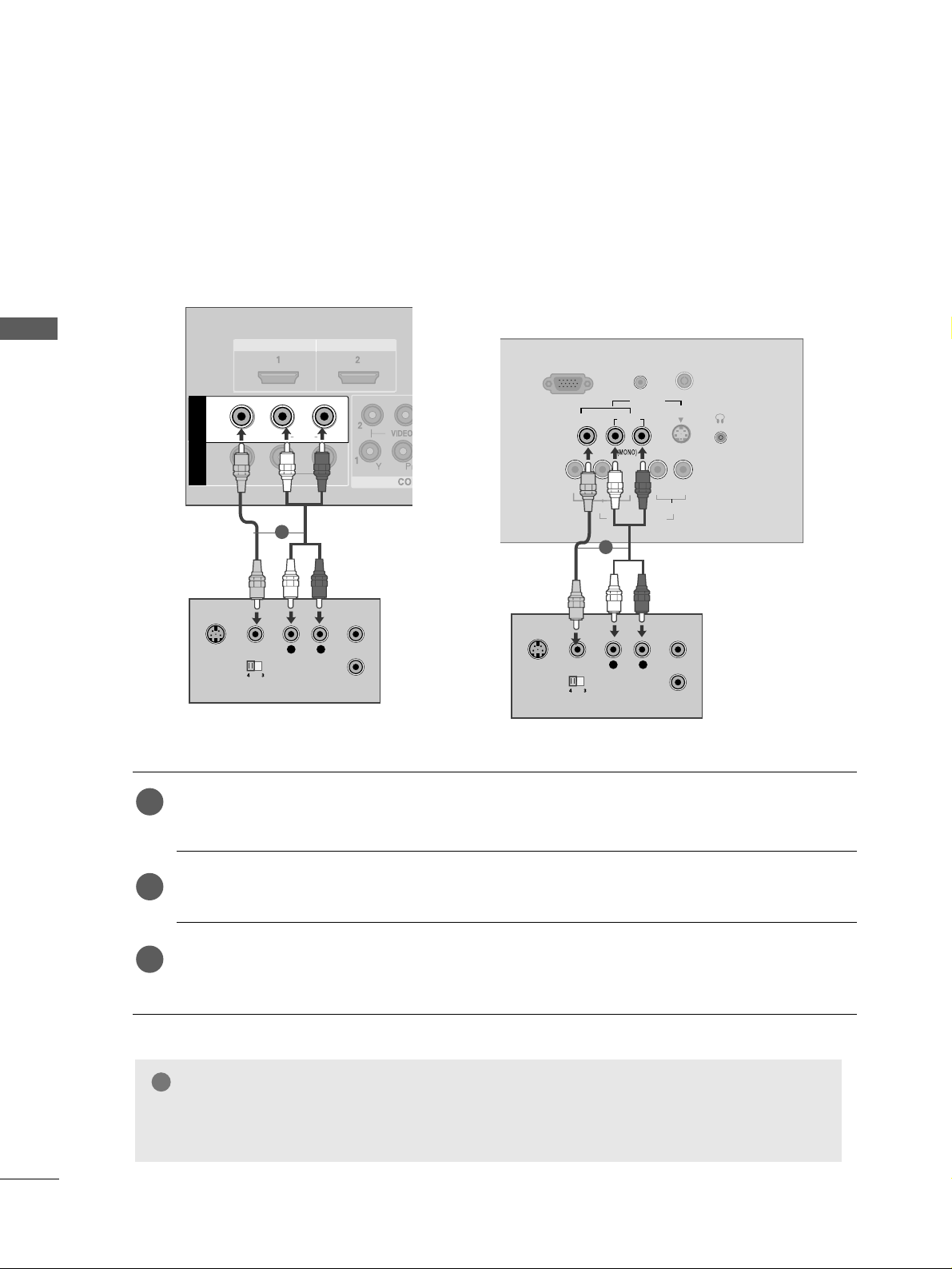
Connecting with a RCA cable
Connect the
AAUUDDIIOO/VVIIDDEEOO
jacks between TV and VCR. Match the jack colours (Video = yellow,
Audio Left = white, and Audio Right = red)
Insert a video tape into the VCR and press PLAY on the VCR. (Refer to the VCR owner’s manual.
)
Select
AAVV11
input source using the
IINNPP UUTT
button on the remote control.
If connected to
AAVV IINN22
, select
AAVV22
input source.
1
2
3
GG
If you have a mono VCR, connect the audio cable from the VCR to the
AAUUDDIIOO LL// MMOONNOO
jack
of the TV.
NOTE
!
26
EXTERNAL EQUIPMENT SETUP
EXTERNAL EQUIPMENT SETUP
L/MONO
R
AUDIO
VIDEO
VIDEO
L
R
AUDIO
HDMI IN HDMI DVI IN
HDMI IN HDMI DVI IN
L
R
S-VIDEO
VIDEO
OUTPUT
SWITCH
ANT IN
ANT OUT
L/L/MONOMONO
R
AUDIOAUDIO
VIDEOVIDEO
AV
IN 1
OUT
VARIABLE ARIABLE AUDIO OUTAUDIO OUT
L
R
S-VIDEO
VIDEO
OUTPUT
SWITCH
ANT IN
ANT OUT
RGB (PC) IN
S-VIDEO
AV IN
VIDEO
L
R
AUDIO
Y
PBPRL R
VIDEO
COMPONENT IN
AUDIO
AUDIO
(RGB/DVI) IN
H/P
ANTENNA IN
1
1
Only 22LG3
***
Page 29
27
EXTERNAL EQUIPMENT SETUP
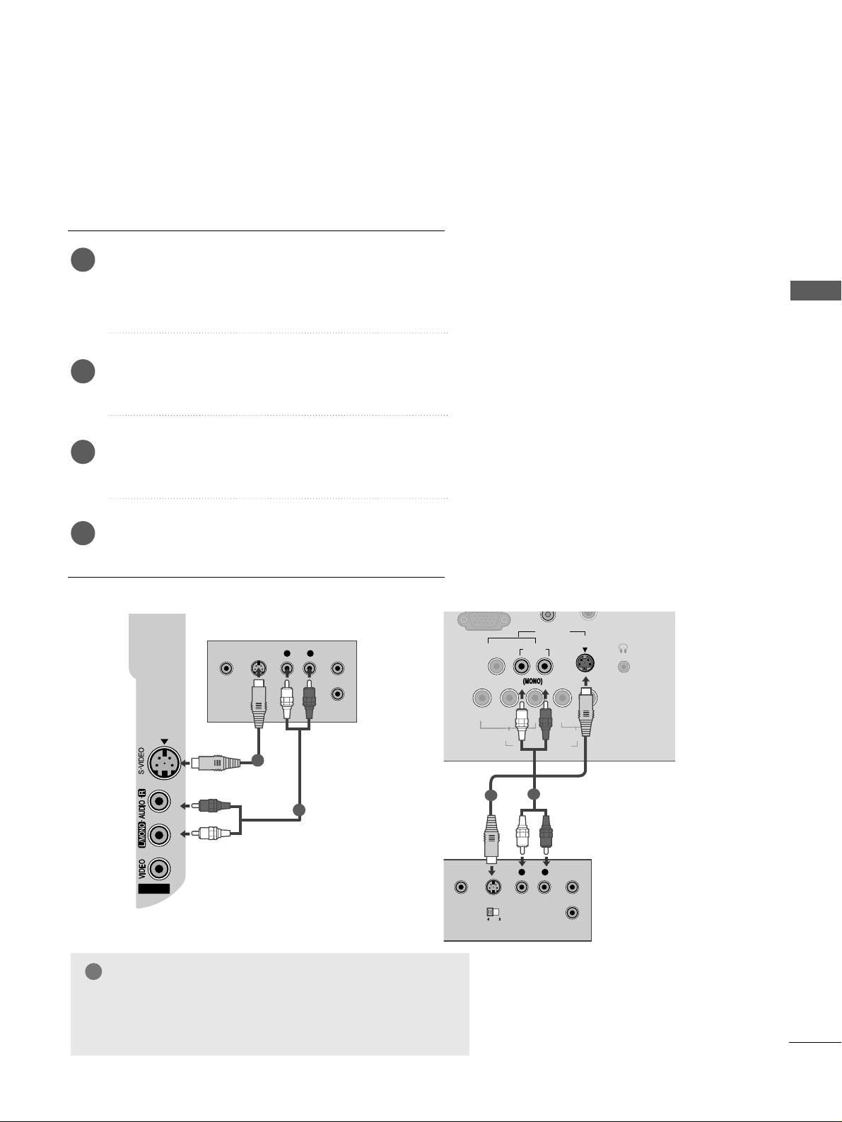
GG
If both S-VIDEO and VIDEO sockets have been conneced to
the S-VHS VCR simultaneously, only the S-VIDEO can be
received.
NOTE
!
Connecting with a S-Video cable
Connect the S-VIDEO output of the VCR to the
SS -- VVIIDDEEOO
input on the TV. The picture quality is
improved; compared to normal composite (RCA cable)
input.
Connect the audio outputs of the VCR to the
AAUUDDIIOO
input jacks on the TV.
Insert a video tape into the VCR and press PLAY on
the VCR. (Refer to the VCR owner’s manual.)
Select
AAVV 22((orAA VV
(Only 22LG3***)
))
input source
using the
IINNPP UUTT
button on the remote control.
2
3
4
1
AV IN 2
L R
S-VIDEOVIDEO
OUTPUT
SWITCH
ANT IN
ANT OUT
1
2
Only 22LG3
***
S-VIDEO
AV IN
VIDEO
L
R
AUDIO
Y
PBPRLR
VIDEO
COMPONENT IN
AUDIO
H/P
ANTENNA IN
L R
S-VIDEOVIDEO
OUTPUT
SWITCH
ANT IN
1
2
Page 30
28
EXTERNAL EQUIPMENT SETUP
EXTERNAL EQUIPMENT SETUP
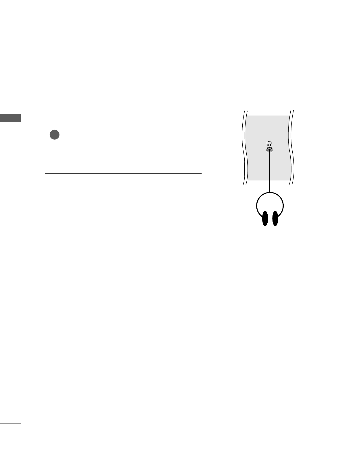
HEADPHONE SETUP
(
Only
22LG3***)
When connecting with a Headphone cable
Insert the headphone plug to the headphone socket of the
set. You can listen to the sound through the headphone. To
adjust the head-phone volume, press the
FF
//
GG
button. If
you press the MUTE button, the sound from the headphone is switched off.
1
H/P
Page 31

29
EXTERNAL EQUIPMENT SETUP
OTHER A/V SOURCE SETUP
Connect the
AAUUDDIIOO/VVIIDDEEOO
jacks between TV and external equipment. Match the jack colours
.
(
Video = yellow, Audio Left = white, and Audio Right = red
)
Select
AAVV22
((orAA VV
(Only 22LG3***)
))
input source using the
IINNPP UUTT
button on the remote control.
If connected to
AAVV IINN11
, select
AAVV11
input source.
Operate the corresponding external equipment.
Refer to external equipment operating guide.
1
2
3
AV IN 2V IN 2
L R
VIDEO
Camcorder
Video Game Set
1
S-VIDEO
AV IN
VIDEO
L
R
AUDIO
Y
PBPRL R
VIDEO
COMPONENT IN
AUDIO
H/P
L R
VIDEO
Camcorder
Video Game Set
1
Only 22LG3
***
Page 32

30
EXTERNAL EQUIPMENT SETUP
EXTERNAL EQUIPMENT SETUP
EXTERNAL STEREO SETUP
(Except 22LG3***)
HDMI IN HDMI DVI IN
HDMI IN HDMI DVI IN
L/ MONO
R
AUDIO
VIDEO
VARIABLE AUDIO OUT
L/MONO
R
AUDIOAUDIO
VIDEOVIDEO
AV
OUT
VARIABLE AUDIO OUT
GG
When connecting with external audio equipments, such as
amplifiers or speakers, please turn the TV speakers off.
(
GG
pp .. 7799
)
GG
Select
VVaa rriiaabbllee OOuu tt
in
AAuudd ii oo
menu to connect the
VVAARRIIAABBLLEE AAUUDDIIOO OOUU TT
jacks.(
GG
pp .. 8800
)
NOTE
!
Use to connected either an external amplifier, or add a subwoofer to your surround sound system.
Connect the input jack of the stereo amplifier to the
VVAARRIIAABBLLEE AAUU DDIIOO OOUU TT
jacks on the TV.
Set up your speakers through your analog stereo
amplifier, according to the instructions provided with
the amplifier.
2
1
11
AV OUTPUT SETUP
(Except 22LG3***)
The TV has a special signal output capability which allows you
to hook up the second TV or monitor.
HDMI IN HDMI DVI IN
L/MONO
R
AUDIOAUDIO
VIDEOVIDEO
AV
OUT
VARIABLE AUDIO OUT
L R
S-VIDEO
VIDEO
Connect the second TV or monitor to the TV’s
AAVV OOUUTT
jacks.
See the Operating Manual of the second TV or monitor
for further details regarding that device’s input settings.
GG
Component, RGB, HDMI input sources cannot be used for
AV out.
GG
We recommend to use the AV OUT jacks for VCR recording.
NOTE
!
2
1
1
Page 33

31
EXTERNAL EQUIPMENT SETUP
R
HDMI IN HDMI DVI IN
AUDIO
(RGB/DVI)
RGB
(PC)
RGB IN
RGB OUTPUT
AUDIO
HDMI IN HDMI DVI IN
HDMI/DVI IN
1
L/MONO
R
AUDIO
VIDEO
VIDEO
L
R
AUDIO
1
2
L/MONO
R
AUDIO
L
R
AUDIO
HDMI IN HDMI DVI IN
HDMI IN HDMI DVI IN
HDMI/DVI IN
1
L/MONO
R
AUDIO
VIDEO
VIDEO
L
R
AUDIO
RGB (PC) IN
S-VIDEO
AV IN
VIDEO
L
R
AUDIO
Y
PBPRLR
VIDEO
COMPONENT IN
AUDIO
AUDIO
(RGB/DVI) IN
H
AN
RGB OUTPUT
AUDIO
1
2
PC SETUP
This TV provides Plug and Play capability, meaning that the PC adjusts automatically to the TV's settings.
Connecting with a D-sub 15 pin cable
Connect the RGB output of the PC to the
RRGGBB((PP CC
))
jack on the TV.
Connect the PC audio output to the
AAUUDDIIOO
jack on the TV.
Turn on the PC and the TV.
Select
RRGGBB PPCC
input source using the
IINN PPUUTT
button on the remote control.
2
3
4
1
Only 22LG3
***
Page 34

32
EXTERNAL EQUIPMENT SETUP
EXTERNAL EQUIPMENT SETUP
NOTE
!
GG
To enjoy vivid picture and sound, connect the PC
to the TV.
GG
Avoid keeping a fixed image on the TV ’s screen
for prolonged periods of time.The fixed image
may become permanently imprinted on the
screen;use a screen saver when possible.
GG
Connect the PC to the RGB (PC) port of the TV;
change the resolution output of PC accordingly.
GG
There may be interference relating to resolution,
vertical pattern, contrast or brightness in PC
mode. Change the PC mode to another resolution or change the refresh rate to another rate
or adjust the brightness and contrast on the
menu until the picture is clear. If the refresh rate
of the PC graphic card can not be changed,
change the PC graphic card or consult the manufacturer of the PC graphic card.
GG
The synchronization input waveform for
Horizontal and Vertical frequencies are separate.
GG
We recommend using 1024 x 768, 60Hz
(42PG1
***
,42PG2
***
XGA PLASMA TV
Models)/1360 x 768, 60Hz(50PG1
***
,
50PG2
***
) /1920 x 1080(42LG 31 F**,
37/42/47/52LG5
***
)
/1366 x 768(26/32/37/42/47LG3
***
)/1680
x 1050(22LG3
***
) for the PC mode, these
should provide the best picture quality.
GG
If the resolution of PC is over SXGA, there will
be no picture on the TV.(Only HD Models)
GG
Connect the audio cable from the PC to the
Audio input on the TV.(Audio cables are not
included with the TV).
GG
If you use too long an RGB-PC cable, there may
be interference on the screen. We recommend
using under 5m of the cable. This provides the
best picture quality.
Supported Display Resolution
31.47 59.94
31.50 60.00
31.25 50.00
44.96 59.94
45.00 60.00
37.50 50.00
33.72 59.94
33.75 60.00
28.125 50.00
67.432 59.94
67. 5 60
56.25 50
Resolution
720x480
720x576
1280x720
1920x1080i
1920x1080p
HDMI-DTV mode
Horizontal Vertical
Frequency(kHz) Frequency(Hz)
Resolution
RGB-PC mode
31.469 59.94
37.879 60.317
48.363 60.004
63.668 59.895
65.290 59.954
Horizontal Vertical
Frequency(kHz) Frequency(Hz)
Only 22LG3***
640x480
800x600
1024x768
1280x1024
1680x1050
Page 35

31.47 59.94
31.50 60.00
31.25 50.00
44.96 59.94
45.00 60.00
37.50 50.00
33.72 59.94
33.75 60.00
28.125 50.00
67.432 59.94
67. 5 60
56.25 50
27 24
33.75 30
33
EXTERNAL EQUIPMENT SETUP
Resolution
720x480
720x576
1280x720
1920x1080i
1920x1080p
HDMI-DTV mode
Horizontal Vertical
Frequency(kHz) Frequency(Hz)
31.47 59.94
31.50 60.00
31.25 50.00
44.96 59.94
45.00 60.00
37.50 50.00
33.72 59.94
33.75 60.00
28.125 50.00
67.432 59.94
67. 5 60
56.25 50
27 24
33.75 30
Resolution
720x480
720x576
1280x720
1920x1080i
1920x1080p
HDMI-DTV mode
Horizontal Vertical
Frequency(kHz) Frequency(Hz)
Resolution
RGB-PC mode
31.468 70.09
31.469 70.09
31.469 59.94
37.879 60.317
48.363 60.004
47.776 59.87
47. 720 59 .799
Horizontal Vertical
Frequency(kHz) Frequency(Hz)
Plasma TV models
Resolution
RGB-PC mode
31.468 70.09
31.469 70.09
31.469 59.94
37.879 60.317
48.363 60.004
47.776 59.87
47. 720 59.799
47. 700 60 .0 0
63.668 59.895
66.587 59.934
Horizontal Vertical
Frequency(kHz) Frequency(Hz)
LCD TV models (Except 22LG3***)
640x350
720x400
640x480
800x600
1024x768
1280x768
1360x768
Supported Display Resolution
Only 42 LG31 F**, 37 /
42/47/52LG5
***
Only
50PG1
***
, 50PG2
***
640x350
720x400
640x480
800x600
1024x768
1280x768
1360x768
1366x768
1280x1024
1920x1080
Page 36

34
EXTERNAL EQUIPMENT SETUP
EXTERNAL EQUIPMENT SETUP
Press the
MMEE NNUU
button and then use
//
button to
select the
PP iiccttuurr ee
menu.
Press the button and then use
//
button to select
SS cc rree eenn
.
Press the button and then use
//
button to select
AAuu tt oo CCoonnffiigg..
.
Press the button to start
AAuu tt oo CCoonnffiigg
..
• When Auto config. has finished, OK will be shown on
screen.
• If the position of the image is still not correct, try Auto
adjustment again.
• If picture needs to be adjusted again after Auto adjustment in RGB (PC), you can adjust the
MMaannuuaa ll CCoonnffiigg..
.
Press the
MMEENNUU
button to return to normal TV viewing.
Press the
RREETTUURRNN orMMEENNUU
(
Only 22LG3
***
)
button to
move to the previous menu screen.
Automatically adjusts picture position and minimizes image
instability. After adjustment, if the image is still not correct,
your TV is functioning properly but needs further adjustment.
AA uu tt oo cc oonnff iigguurree
This function is for automatic adjustment of the screen position, clock, and phase. The displayed image will be unstable for
a few seconds while the auto configuration is in progress.
1
2
3
4
5
1
3 4
Screen Setup for PC mode
Auto Configure (RGB [PC] mode only)
Picture Mode
Colour Temperature
XD
Advanced
Aspect Ratio
Picture Reset
Screen
Picture
Screen
Auto config.
Manual Config.
XGA Mode
Reset
To Set
Auto Config. G
2
Picture
Picture Mode
Colour Temperature
XD
Advanced
Aspect Ratio
Picture Reset
Screen
To Set
Screen G
Page 37

35
EXTERNAL EQUIPMENT SETUP
If the picture is not clear after auto adjustment and especially if
characters are still trembling, adjust the picture phase manually.
It’s not available to use Phase, Clock function in COMPONENT
(480i/480p/576i/576p/720p/1080i/1080p), HDMI
(480p/576p/720p/1080i/1080p).
CCll oocckk
This function is to minimize any vertical bars or stripes
visible on the screen background the horizontal screen
size will also change.
PP hh aassee
This function allows you to remove any horizontal noise
and clear or sharpen the image of characters.
Press the
MMEE NNUU
button and then use
//
button to
select the
PP iiccttuurree
menu.
Press the button and then use
//
button to select
SS cc rree eenn
.
Press the button and then use
//
button to select
MMaannuuaa ll CCoonnffiigg..
.
Press the button and then use
//
button to select
PP hhaa ssee, CCll oo cc kk, HH--PP ooss iittii oonn
or
VV--PP ooss iittii oonn
.
Press the
//
button to make appropriate adjustments.
Press the
MMEENNUU
button to return to normal TV viewing.
Press the
RREETTUURRNN orMMEENNUU
(
Only 22LG3
***
)
button to
move to the previous menu screen.
1
2
3
4
5
6
Manual Configure (Adjustment for screen Phase, Clock, Position)
(RGB [PC] mode only)
3 4 5
1
Picture Mode
Colour Temperature
XD
Advanced
Aspect Ratio
Picture Reset
Screen
Picture
2
Picture
Picture Mode
Colour Temperature
XD
Advanced
Aspect Ratio
Picture Reset
Screen
To Set
Screen G
Screen
Auto config.
Manual Config.
XGA Mode
Reset
Phase 51
Clock 50
H-Position 50
V-Position 50
Manual Config. G
Page 38

36
EXTERNAL EQUIPMENT SETUP
3 4
This feature is not available for all models.
To view a normal picture, match the resolution of RGB mode
and selection of XGA mode.
This function works in the following mode: RGB[PC] mode.
Press the
MMEE NNUU
button and then use
//
button to
select the
PP iiccttuurr ee
menu.
Press the button and then use
//
button to select
SS cc rree eenn
.
Press the button and then use
//
button to select
XXGG AA MMooddee
.
Press the button and then use
//
button to select
the desired XGA resolution.
Press the
MMEENNUU
button to return to normal TV viewing.
Press the
RREETTUURRNN
button to move to the previous menu
screen.
Selecting XGA mode (Except 42PG1
***
, 42PG2
***
, 22LG3
***
)
1
2
3
4
5
EXTERNAL EQUIPMENT SETUP
1
Picture Mode
Colour Temperature
XD
Advanced
Aspect Ratio
Picture Reset
Screen
Picture
2
Picture
Picture Mode
Colour Temperature
XD
Advanced
Aspect Ratio
Picture Reset
Screen
To Set
Screen G
Screen
Auto Config.
Manual Config.
XGA Mode
Reset
1024x768
1280x768
1360x768
1366x768
XGA Mode G
* Except PLASMA TV models
Page 39

37
EXTERNAL EQUIPMENT SETUP
This function operates in current mode.
To initialize the adjusted value
Press the MENU button and then use
//
button to
select the
PP iiccttuurr ee
menu.
Press the button and then use
//
button to select
SS cc rree eenn
.
Press the button and then use
//
button to select
RRee ssee tt
.
Press the button.
Press the
MMEENNUU
button to return to normal TV viewing.
Press the
RREETTUURRNN orMMEENNUU
(
Only 22LG3
***
)
button to
move to the previous menu screen.
1
2
3
4
5
Initializing
(Reset to original factory settings)
3 4
1
Picture Mode
Colour Temperature
XD
Advanced
Aspect Ratio
Picture Reset
Screen
Picture
2
Picture
Picture Mode
Colour Temperature
XD
Advanced
Aspect Ratio
Picture Reset
Screen
To Set
Screen G
Screen
Auto config.
Manual Config.
XGA Mode
Reset
To Set
Reset G
Page 40

WATCHING TV / PROGRAMME CONTROL
WATCHING TV / PROGRAMME CONTROL
38
REMOTE CONTROL KEY FUNCTIONS (Only 22LG3
***
)
When using the remote control, aim it at the remote control sensor on the TV.
RATIO
POWER
TV
INPUT
Switches the set on from standby or off to standby.
Returns to the TV viewing from any mode.
Switches the set on from standby.
If you press the button once, the input source OSD will
appear on screen as shown. Press the
DD/ EE
button and
then OK button to select the desired input source.
MUTE
PSM
SSM
I/II
Switches the sound on or off.
Recalls your preferred picture setting.
Recalls your preferred sound setting.
Selects the sound output.
0~9 number
button
Selects a programme.
Selects numbered items in a menu.
Switches the set on from standby.
LIST
Q.VIEW
Displays the programme table.
Returns to the previously viewed programme.
Page 41

WATCHING TV / PROGRAMME CONTROL
39
RATIO
THUMBSTICK
(Up/Down/Left/
Right)
OK
Allows you to navigate the on-screen menus and adjust
the system settings to your preference.
Adjusts the volume.
Selects a programme.
Switches the set on from standby. (Up/Down)
Accepts your selection or displays the current mode.
MENU
SLEEP
RATIO
Selects a menu.
Sets the sleep timer.
Selects your desired picture format.
Coloured
buttons
TELETEXT
BUTTONS
These buttons are used for teletext (only
TTEELLEETTEEXXTT
models) or
PPrroogg rraa mmmmee ee ddii tt
.
These buttons are used for teletext.
For further details, see the ‘Teletext’ section.
Installing Batteries
■
Open the battery compartment cover on the back side and install the
batteries matching correct polarity (+with +,-with -).
■
Install two 1.5V AAA batteries. Don’t mix old or used batteries with
new ones.
■
Close cover.
Page 42

WATCHING TV / PROGRAMME CONTROL
WATCHING TV / PROGRAMME CONTROL
40
REMOTE CONTROL KEY FUNCTIONS (
Except
Plasma TV models, 22LG3
***
)
When using the remote control, aim it at the remote control sensor on the TV.
MUTE
PIP
AV MODE
FAV
TV
INPUT
STB
POWER
Q. MENU
MENU
OK
123
456
7809
LIST
Q.VIEW
DVD
TIME
SIZE
UPDATE
REVEAL
INDEX
HOLD TEXT
RETURN
P
MODE
POWER
INPUT
Selects the remote operating modes.
Switches the TV on from standby or off to standby.
External input mode rotate in regular sequence.
Switches the TV on from standby.
Q. MENU
MENU
Select the desired quick menu source.
Selects a menu.
Clears all on-screen displays and returns to TV viewing
from any menu.
See a list of AV devices connected to TV.
When you toggle this button, the Simplink menu
appears at the screen.
RETURN
PIP
AV MODE
Allows the user to move return one step in an interactive
application or other user interaction function.
Switches the sub picture PIP, DW mode.
It helps you select and set images and sounds when
connecting AV devices.
Coloured
buttons
These buttons are used for teletext (on
TTEELLEETTEEXXTT
models only) ,
PPrroogg rraa mmmmee ee ddii tt
.
TELETEXT
BUTTONS
These buttons are used for teletext.
For further details, see the ‘Teletext’ section.
1
1
Page 43

41
WATCHING TV / PROGRAMME CONTROL
MUTE
PIP
AV MODE
FAV
TV
INPUT
STB
POWER
Q. MENU
MENU
OK
123
456
7809
LIST
Q.VIEW
DVD
TIME
SIZE
UPDATE
REVEAL
INDEX
HOLD TEXT
RETURN
P
VOLUME +/-
FAV
MUTE
Programme
//
0~9 number
button
LIST
Q.VIEW
Adjusts the volume.
Displays the selected favourite programme.
Switches the sound on or off.
Selects a programme.
Selects a programme.
Selects numbered items in a menu.
Displays the programme table.
Returns to the previously viewed programme.
Installing Batteries
■
Open the battery compartment cover on the back and install the
batteries matching correct polarity (+with +,-with -).
■
Install two 1.5V AAA batteries. Do not mix old or used batteries
with new ones.
■
Close cover.
VCR/DVD
control buttons
Controls some video cassette recorders or DVD players.
Control connected AV devices by pressing the
// //
//
, OK buttons and buttons for
G,A
,
ll ll
,
FF
andGG.
(The
Ô
button does not provide such functions.)
THUMBSTICK
(Up/Down/Left
Right)
OK
Allows you to navigate the on-screen menus and adjust
the system settings to your preference.
Accepts your selection or displays the current mode.
Page 44

WATCHING TV / PROGRAMME CONTROL
WATCHING TV / PROGRAMME CONTROL
42
REMOTE CONTROL KEY FUNCTIONS (Only Plasma TV models)
When using the remote control, aim it at the remote control sensor on the TV.
MUTE
PIP
AV MODE
FAV
RATIO
INPUT
SOUND
POWER
Q. MENU
MENU
OK
123
456
7809
LIST
Q.VIEW
PICTURE
TIME
SIZE
UPDATE
REVEAL
INDEX
HOLD TEXT
RETURN
P
RATIO
SOUND
POWER
PICTURE
INPUT
Selects your desired picture format.
To select the sound appropriate to your viewing programme.
Switches the TV on from standby or off to standby.
Adjusts the factory preset picture according to the room.
External input mode rotate in regular sequence.
Switches the TV on from standby.
Q. MENU
MENU
Select the desired quick menu source.
Selects a menu.
Clears all on-screen displays and returns to TV viewing
from any menu.
See a list of AV devices connected to TV.
When you toggle this button, the Simplink menu
appears at the screen.
RETURN
PIP
AV MODE
Allows the user to move return one step in an interactive
application or other user interaction function.
Switches the sub picture PIP, DW mode.
It helps you select and set images and sounds when
connecting AV devices.
Coloured
buttons
These buttons are used for teletext (on
TTEELLEETTEEXXTT
models only) ,
PPrroogg rraa mmmmee ee ddii tt
.
TELETEXT
BUTTONS
These buttons are used for teletext.
For further details, see the ‘Teletext’ section.
Page 45

WATCHING TV / PROGRAMME CONTROL
43
MUTE
PIP
AV MODE
FAV
RATIO
INPUT
SOUND
POWER
Q. MENU
MENU
OK
123
456
7809
LIST
Q.VIEW
PICTURE
TIME
SIZE
UPDATE
REVEAL
INDEX
HOLD TEXT
RETURN
P
VOLUME +/-
FAV
MUTE
Programme
//
0~9 number
button
LIST
Q.VIEW
Adjusts the volume.
Displays the selected favourite programme.
Switches the sound on or off.
Selects a programme.
Selects a programme.
Selects numbered items in a menu.
Displays the programme table.
Returns to the previously viewed programme.
Installing Batteries
■
Open the battery compartment cover on the back and install the
batteries matching correct polarity (+with +,-with -).
■
Install two 1.5V AAA batteries. Do not mix old or used batteries
with new ones.
■
Close cover.
VCR/DVD
control buttons
Controls some video cassette recorders or DVD players.
Control connected AV devices by pressing the
// //
//
, OK buttons and buttons for
G,A
,
ll ll
,
FF
andGG.
(The
Ô
button does not provide such functions.)
THUMBSTICK
(Up/Down/Left
Right)
OK
Allows you to navigate the on-screen menus and adjust
the system settings to your preference.
Accepts your selection or displays the current mode.
Page 46

WATCHING TV / PROGRAMME CONTROL
WATCHING TV / PROGRAMME CONTROL
44
Press the
++ //--((oo rr VVOOLL
F
// G))
button to adjust the volume.
If you wish to switch the sound off, press the
MMUU TTEE
button.
You can cancel the Mute function by pressing the
MMUUTT EE oorr ++ // --
(( oorr VV OOLL
F
// G))
button.
PROGRAMME SELECTION
TURNING ON THE TV
When your TV is turned on, you will be able to use its features.
Firstly, connect the power cord correctly.
At this stage, the TV switches to standby mode.
■
In standby mode to turn TV on, press the ,
IINNPP UUTT,PP DD//
EE
((oorr PP
//
oorr PP RR DD// EE))
button on the TV or press the
PP OOWWEERR, TTVV ((OOnnllyy 2222 LLGG33 ******))
,
IINNPP UUTT, PP
//
(( oorr PP RR DD// EE)), NNUUMMBBEERR((00~99 ))
buttons on the remote control
and the TV will switch on.
1
VOLUME ADJUSTMENT
Press the
PP
//
(( oorr PP RR DD// EE))
or
NN UUMMBBEERR
buttons to select a pro-
gramme number.
2
3
1
1
Initializing Guide
Note:
a. It will automatically disappear after approx. 40 seconds unless a button is pressed.
b. “In -Store” mode is only for shop display and not for general customer use.
c. "Home” mode is the optimal setting for home environments, and is the TV's default mode.
d. "In-Store" mode is the optimal setting for store environments. If a user modifies image quality data,
“In- Store” mode initializes the product to the image quality set by us after a certain period of time.
e. The mode (Home, In- Store) can be changed by executing Factory Reset in the Option menu.
If the OSD (On Screen Display) is displayed on the screen after turning on the TV, you can adjust the
LL aa nngguuaaggee,LL oocc aa tt iioonn,, AAuuttoo TTuu nn iinngg
.
Page 47

WATCHING TV / PROGRAMME CONTROL
45
QUICK MENU
(
Except
22LG3
***
)
Your TV's OSD (On Screen Display) may differ slightly from that shown in this
manual.
Q.Menu (Quick Menu) is a menu of features which users might use frequently.
•
AAssppeecctt RRaattiioo
:
Selects your desired picture format.
For Zoom Setting, select 14:9, Zoom1 and Zoom2 in Ratio Menu. After completing
Zoom Setting, the display goes back to Q.Menu.
•
PP oowweerr SS aa vviinngg
(only Plasma TV Models)
: Adjusts screen brightness to reduce the power
consumption of the set.
•
BBaa cc kkllii gghhtt
(only LCD TV Models):Adjusts screen brightness. It returns to the default
settings brightness by changing mode source.
•
PP iiccttuurree MMooddee
:
Selects your desired Picture Mode.
•
SSoouunndd MMoodd ee
: It is a feature to automatically set the sound combination which it deems the
best for the images being watched.
Selects your desired Sound Mode.
•
MMuull ttii AAuu ddiioo ::
Selects the sound output.
•
PPrroogg rraa mmmmee EEddiitt ::
Adjusts the stored programmes by delete, copy, move or skip.
•
SSllee eepp TTii mm eerr
:
Selects the sleep timer.
Aspect Ratio
power Saving
Backlight
Picture Mode
Sound Mode
Multi Audio
programme Edit
Sleep Timer
FF
4 : 3
GG
Zoom Setting
0
0
Sport
Sport
L+R
To Set
Off
Q. MENU
DDEE
FF GG
RETURN
Press the
QQ..MMEENNUU
button and then
//
button to
display each menu.
Press the
//
button to select your desired Source.
Press the
QQ..MMEENNUU
button to return to normal TV viewing.
1
2
3
* PLASMA TV models only
* LCD TV models only
Page 48

WATCHING TV / PROGRAMME CONTROL
WATCHING TV / PROGRAMME CONTROL
46
ON SCREEN MENUS SELECTION AND ADJUSTMENT
Press the
MMEE NNUU
button and then
//
button to display each menu.
Press the button and then
//
button to select a menu item.
Change the setting of an item in the sub or pull-down menu with
//
button.
You can move to a higher level menu by pressing the
OO KK
button.
Your TV's OSD (On Screen Display) may differ slightly from that shown in this manual.
The OSD mainly use pictures for the Plasma TV models.
NOTE
!
a. The OSD (On Screen Display) function enables you to adjust the screen status conveniently since it
provides graphical presentation.
b. In this manual, the OSD (On Screen Display) may be different from your TV’s because it is just
example to help the TV operation.
c. In the teletext mode, menus are not displayed.
Setup MENU
Picture MENU
Audio MENU
Time MENU
Option MENU
1
2
3
Language
SIMPLINK
Key Lock
ISM Method
Power Saving
Set ID
Factory Reset
Option
Clock
Off Time
On Time
Sleep Timer
Auto Sleep
Time
Auto Tuning
Manual Tuning
Programme Edit
Favourite Programme
Setup
Sound Mode
Auto Volume
Balance 0
TV Speaker
Audio Out
Audio
Language
SIMPLINK
Key Lock
Set ID
Power Indicator
Factory Reset
Option
or
PPLLAASS MMAA TTVV
mmooddeellss
LL CCDD TT VV
mmooddeellss
Picture Mode
Colour Temperature
XD
Advanced
Aspect Ratio
Picture Reset
Screen
Picture
Except 22LG3
***
Except 22LG3
***
Page 49

WATCHING TV / PROGRAMME CONTROL
47
Press the
MMEENNUU
button and then
//
button to select the
SSeettuupp
menu.
Press the button and then
//
button to select
AAuuttoo
TTuunniinngg
.
Press the button and then
//
button to select
SSyysstteemm
.
Press the
//
button to select a TV system menu;
BG: PAL B/G, SECAM B/G (Europe / East Europe / Asia /
NewZealand / M.East / Africa / Australia)
I : PAL I/II (U.K. / Ireland / Hong Kong / South Africa)
DK: PAL D/K, SECAM D/K (East Europe / China / Africa / CIS)
M : (USA / Korea / Philippines)
Press the
//
button to select
SSttoorraaggee FFrroomm
.
Press the
//
button or NUMBER buttons to select the ini-
tial programme number. If you use NUMBER buttons, any
number under 10 is entered with a numeric ‘0’ in front of it,
i.e.‘
00 55
’ for 5.
Press the
//
button to select
SSeeaarrcchh
.
Press the button to begin auto tuning.
All receivable stations are stored.
To stop auto tuning, press the
RREETTUU RRNN orMMEE NNUU
(
Only
22LG3
***
)
button.
When auto tuning is complete, the Programme edit menu
appears on the screen. See the Programme edit section to edit
the stored programme.
Press the
MMEENNUU
button to return to normal TV viewing.
Press the
RREETTUURRNN orMMEENNUU
(
Only 22LG3
***
)
button to
move to the previous menu screen.
1
2
3
4
5
6
7
8
9
Up to 100 TV stations can be stored by programme numbers (0 to 99). Once you
have preset the stations, you will be able to use the P
//
(( oorr PP RR DD// EE))
or
NUMBER buttons to scan the stations you have programmed.
Stations can be tuned using automatic or manual modes.
All stations which can be received are stored by this method. It is
recommended that you use Auto tuning during installation of this TV.
AUTO PROGRAMME TUNING
Auto Tuning
System
Storage From
Search
System G
2
Setup
Auto Tuning
Manual Tuning
Programme Edit
Favourite Programme
To Set
Auto Tuning G
3 4 5 6
7
8
Auto Tuning
C 05 BG
5 35%
BG
I
DK
M
1
Auto Tuning
Manual Tuning
Programme Edit
Favourite Programme
Setup
Page 50

WATCHING TV / PROGRAMME CONTROL
WATCHING TV / PROGRAMME CONTROL
48
MANUAL PROGRAMME TUNING
Press the
MMEE NNUU
button and then
//
button to select
the
SS eettuu pp
menu.
Press the button and then
//
button to select
MMaannuuaa ll TTuu nniinngg
.
Press the button and then
//
button to select
SSttoorraaggee
.
Press the
//
button or NUMBER buttons to select the
desired programme number (0 to 99). If you use NUMBER
buttons, any number under 10 is entered with a numeric ‘0’
in front of it, i.e. ‘
00 55
’ for 5.
Press the
//
button to select
SS yyss tt eemm
.
Press the
//
button to select a TV system menu;
BG: PAL B/G, SECAM B/G (Europe / East Europe / Asia /
NewZealand / M.East / Africa / Australia)
I : PAL I/II (U.K. / Ireland / Hong Kong / South Africa)
DK : PAL D/K, SECAM D/K (East Europe / China / Africa / CIS)
M : (USA / Korea / Philippines)
Press the
//
button to select
BBaa nndd
.
Press the button and then
//
button to select
VV// UUHHFF
or
CCaabb llee
.
Press the
//
button to select
CChhaannnnee ll
.
You can select the desired programme number with the
//
button or NUMBER buttons. If possible, select the programme number directly with the number buttons. Any
number under 10 is entered with a numeric ‘0’ in front of it,
i.e. ‘
00 55
’ for 5.
Press the
//
button to select
SS eeaarrcchh
.
Press the
//
button to commence searching. If a station
is found the search will stop.
Press the
OO KK
button to store it.
To store another station, repeat steps 33to
11 33
.
Press the
MMEENNUU
button to return to normal TV viewing.
Press the
RREETTUURRNN orMMEENNUU
(
Only 22LG3
***
)
button to
move to the previous menu screen.
Manual programme lets you manually tune and arrange the
stations in whatever order you desire.
1
2
3
4
5
6
7
8
9
10
11
12
13
14
15
73 4 5 6
8 9
10 11 12
1
Auto Tuning
Manual Tuning
Programme Edit
Favourite Programme
Setup
2
Setup
Auto Tuning
Manual Tuning
Programme Edit
Favourite Programme
To Set
Manual Tuning G
Manual Tuning
Storage
System
Band
Channel
Fine
Search
Name
Booster
Storage G
99
Page 51

WATCHING TV / PROGRAMME CONTROL
49
FINE TUNING
Press the
MMEE NNUU
button and then
//
button to select
the
SSeettuupp
menu.
Press the button and then
//
button to select
MMaannuuaa ll TTuu nniinngg
.
Press the button and then
//
button to select
FF iinnee
.
Press the button and then
//
button to fine tune for
the best picture and sound.
Press the
OO KK
button to store it.
Press the
MMEENNUU
button to return to normal TV viewing.
Press the
RREETTUURRNN orMMEENNUU
(
Only 22LG3
***
)
button to
move to the previous menu screen.
1
2
3
4
5
6
Normally fine tuning is only necessary if reception is poor.
3 4 5
1
Auto Tuning
Manual Tuning
Programme Edit
Favourite Programme
Setup
2
Setup
Auto Tuning
Manual Tuning
Programme Edit
Favourite Programme
To Set
Manual Tuning G
Manual Tuning
Storage
System
Band
Channel
Fine
Search
Name
Booster
Fine G
F / G
Page 52

WATCHING TV / PROGRAMME CONTROL
WATCHING TV / PROGRAMME CONTROL
50
ASSIGNING A STATION NAME
You can assign a station name up to five characters to each programme number.
Press the
MMEE NNUU
button and then
//
button to select
the
SSeettuupp
menu.
Press the button and then
//
button to select
MMaannuuaa ll TTuu nniinngg
.
Press the button and then
//
button to select
NN aa mmee
.
Press the button and then
//
button. You can use a
blank, ++, --, the number 00to 99and the alphabet AAto ZZ.
Press the
//
button to select the position and make
your choice of the second character, and so on.
Press the
OO KK
button to store it.
Press the
MMEENNUU
button to return to normal TV viewing.
Press the
RREETTUURRNN orMMEENNUU
(
Only 22LG3
***
)
button to
move to the previous menu screen.
1
2
3
4
5
6
7
3 4 5 6
1
Auto Tuning
Manual Tuning
Programme Edit
Favourite Programme
Setup
2
Setup
Auto Tuning
Manual Tuning
Programme Edit
Favourite Programme
To Set
Manual Tuning G
Manual Tuning
Storage
System
Band
Channel
Fine
Search
Name
Booster
Name G
C 05
Page 53

WATCHING TV / PROGRAMME CONTROL
51
In some models,
BBoooo ssttee rr
is an optional function. Only a set
with
BBoooo ssttee rr
can perform this function.
If reception is poor select
BBoooo sstteerr
to On.
When the signal is strong, select “OFF”.
BOOSTER
Press the
MMEE NNUU
button and then
//
button to select
the
SS eettuupp
menu.
Press the button and then
//
button to select
MMaannuuaa ll TTuu nniinngg
.
Press the button and then use
//
button to select
BBoooosstteerr
.
Press the button and then use
//
button to select
OO nnorOO ffff
.
Press the
MMEENNUU
button to return to normal TV viewing.
Press the
RREETTUURRNN orMMEENNUU
(
Only 22LG3
***
)
button to
move to the previous menu screen.
1
2
3
4
5
3 4 5 6
1
Auto Tuning
Manual Tuning
Programme Edit
Favourite Programme
Setup
2
Setup
Auto Tuning
Manual Tuning
Programme Edit
Favourite Programme
To Set
Manual Tuning G
Manual Tuning
Storage
System
Band
Channel
Fine
Search
Name
Booster
Booster G
Off
On
Page 54

WATCHING TV / PROGRAMME CONTROL
WATCHING TV / PROGRAMME CONTROL
52
PROGRAMME EDIT
This function enables you to delete or skip stored programmes.
Also you can move some stations to other programme numbers
or copy a blank station data into the selected programme number.
Press the
MMEE NNUU
button and then
//
button to select
the
SSeettuupp
menu.
Press the button and then
//
button to select
PPrroogg rraa mmmmee EEddiitt
.
Press the button to display the
Programme edit menu.
AA
DDeelleettiinngg aa pprrooggrraammmmee
1.Select a programme to be deleted with the
// //
//
button.
2.Press the RED button twice.
The selected programme is deleted, all the following
programmes are shifted up one position.
AA
CCooppyyiinngg aa pprrooggrraammmmee
1.Select a programme to be copied with the
// //
//
button.
2.Press the GREEN button.
All the following programmes are shifted down one position.
AA
MMoovviinngg aa pprrooggrraammmmee
1.Select a programme to be moved with the
// // //
button.
2.Press the YELLOW button.
3.Move the programme to the desired programme number with
the
// // //
button.
4.Press the YELLOW button again to release this function.
AA
SSkkiippppiinngg aa pprrooggrraammmmee nnuummbbeerr
1.Select a programme number to be skipped with the
//
// //
button.
2.Press the BLUE button. The skipped programme turns to blue.
3.Press the BLUE button again to release the skipped programme.
When a programme number is skipped it means that you will
be unable to select it using the
//
button during normal
TV viewing. If you wish to select the skipped programme,
directly enter the programme number with the NUMBER buttons or select it in the programme edit or table menu.
Press the
MMEENNUU
button to return to normal TV viewing.
Press the
RREETTUURRNN orMMEENNUU
(
Only 22LG3
***
)
button to
move to the previous menu screen.
1
2
3
4
3
Programme Edit
Delete
Move
Copy
Skip
0C03 5S69
1 BLN 03 6 S 17
2 C 12 7 S 22
3 S 66 8 C 09
4 S 67 9 C 11
1
Auto Tuning
Manual Tuning
Programme Edit
Favourite Programme
Setup
2
Setup
Auto Tuning
Manual Tuning
Programme Edit
Favourite Programme
To Set
Programme Edit G
Page 55

WATCHING TV / PROGRAMME CONTROL
53
FAVOURITE PROGRAMME
Press the
MMEENNUU
button and then
//
button to select the
SSeettuupp
menu.
Press the button and then
//
button to select
FFaavvoouurriittee PPrrooggrraammmmee
.
Press the button.
Press the
//
button to select - - - - - - -.
Select a desired programme with the
//
button or NUMBER buttons. Any number under 10 is entered with a numeric
‘0’in front of it, i.e.‘
00 55
’ for 5.
To store another programme, repeat steps
44
to 55.
You can store up to 8 programmes.
Press the
MMEENNUU
button to return to normal TV viewing.
Press the
RREETTUURRNN orMMEENNUU
(
Only 22LG3
***
)
button to
move to the previous menu screen.
This function lets you select your favourite programmes directly.
Repeatedly press the FAV button to select stored favourite
programmes.
Repeatedly press the YELLOW button to select stored favourite
programmes (Only 22LG3
***
).
1
2
3
4
5
6
7
1
2 3 4 5
Auto Tuning
Manual Tuning
Programme Edit
Favourite Programme
Setup
Setup
Auto Tuning
Manual Tuning
Programme Edit
Favourite Programme
-- -----
-- -----
-- -----
-- -----
-- -----
-- -----
-- -----
-- -----
Favourite Programme G
Page 56

WATCHING TV / PROGRAMME CONTROL
WATCHING TV / PROGRAMME CONTROL
54
SELECTING THE PROGRAMME LIST
You can check which programmes are stored in the memory by displaying the programme list.
AA
DDii ssppll aayyii nngg pprroogg rraammmmee ll iisstt
Press the
LLIISS TT
button to display the Programme
list
menu.
The programme
list
appears on the screen.
One programme
list
contains ten programmes as shown.
AA
SSee lleeccttiinn gg aa pprroogg rraammmmee ii nn tthhee pprroogg rraammmmee ll iisstt
Select a programme with the
// // //
button.
Then press the
OO KK
button. The TV switches to the chosen
programme number.
AA
PPaaggii nngg tthhrroouugghh aa pprroogg rraammmmee ll iisstt
There are 10 programme table pages in which contain 100 pro
grammes. Pressing the
// // //
button repeatedly turns the
pages.
Press the
LL IISSTT
button to return to normal TV viewing.
NOTE
!
a. You may find some blue programmes. They have been set up
to be skipped by auto programming or in the programme edit
mode.
b. Some programmes with the channel number shown in the
programme list indicate there is no station name assigned.
Programme List
0C03 5S69
1 BLN 03 6 S 17
2 C 12 7 S 22
3 S 66 8 C 09
4 S 67 9 C 11
Page 57

WATCHING TV / PROGRAMME CONTROL
55
(
Except 22LG3
***
)
32
Option
Language
SIMPLINK
Key Lock
ISM Method
Power Saving
Set ID
Factory Reset
SIMPLINK G
Off
On
1
This function operates only with devices with the SIMPLINK logo.
Please check the SIMPLINK logo.
The product might not function properly when using it with other
products with HDMI-CEC function.
This allows you to control and play other AV devices connected to
the display through HDMI cable without additional cables and settings.
If you do not require the SIMPLINK menu, select “Off”.
Press the
MMEE NNUU
button and then
//
button to select
the
OOpp ttiioonn
menu.
Press the button and then
//
button to select
SS IIMMPPLLIINNKK
.
Press the button and then
//
button to select
OOnn
or
OOffff
.
Press the
MMEENNUU
button to return to normal TV viewing.
Press the
RREETTUURRNN
button to move to the previous menu
screen.
1
2
3
4
Language
SIMPLINK
Key Lock
ISM Method
Power Saving
Set ID
Factory Reset
Option
Page 58

WATCHING TV / PROGRAMME CONTROL
WATCHING TV / PROGRAMME CONTROL
56
NOTE
!
GG
Connect the HDMI/DVI IN or HDMI IN terminal of the TV to the rear terminal and Side terminal (HDMI
terminal) of the SIMPLINK device with the HDMI cable.
GG
After connecting the HDMI terminal for the home theatre with SIMPLINK function using the above
method, connect the VARIABLE AUDIO OUT terminal on the back of the TV to the VARIABLE AUDIO IN
terminal on the back of the SIMPLINK device with the VARIABLE AUDIO OUT cable.
GG
When operating an external device with SIMPLINK, press the TV button from the MODE button on the
remote control.
GG
When you switch the Input source using the INPUT button on the remote control, you can stop the
operation of a device controlled by SIMPLINK.
GG
When you select or operate a media device with home theatre function, the speaker automatically
switches to home theatre speaker (HT speaker).
DD iisscc ppllaayy bbaacc kk
Control connected AV devices by pressing the
// // //
,
OK, G, A,
ll ll
, FFand GGbuttons.
(The
Ô
button does not provide such functions)
DD iirreecctt PPllaayy
After connecting AV devices to the TV, you can directly control the devices and play media without additional settings.
SSeelleecctt AAVV dd ee vviiccee
Enables you to select one of the AV devices connected to the TV and operate it.
PPoowweerr ooffff aa llll dd eevviicceess
When you switch off the TV, all connected devices are turned off.
SSwwiittcchh aauuddiioo--oouutt
Offers an easy way to switch audio-out.
-Sync Power on : When you play the connected AV device, TV will automatically turn on.
** AA dd ee vviiccee,, wwhhiicchh iiss ccoonnnneecctt eedd ttoo tthhee TTVV tthh rr oouugghh aa HHDDMMII ccaa bbllee bb uutt ddooee ss nnoo tt ssuupp ppoo rr tt SSIIMMPP LLIINNKK,, ddoo eess nn oott
pprroovviidd ee tt hhii ss ffuunnccttiioonn..
SIMPLINK Functions
TTVV vvii eewwiinngg ::
Switch to the previous TV programme
regardless of the current mode.
DDIISS CC ppll aa yybb aacckk ::
Select and play discs. When
multiple discs are available, the titles of the discs are
conveniently displayed at the bottom of the screen.
VVCCRR pp llaayybbaacc kk ::
Control the connected VCR.
HHDDDD RReecc oorr ddii nnggss ppllaa yybb aacckk ::
Control recordings
stored in HDD.
AAuu ddii oo OOuutt ttoo HHoomm ee tthheeaatteerr//AAuu ddii oo OOuutt ttoo TTVV ::
Select Home theater or TV speaker for Audio Out.
Selected Device
When device is not
connected
(displayed in gray)
When a device is
connected (displayed
in bright colour)
1
2
3
4
5
1
2
3
4
5
SIMPLINK Menu
Press the
// // //
button and then OK button to select the desired SIMPLINK source.
DDEE
OK
TV
DISC
VCR
HDD Recorder
SPEAKER
TV Speaker
Page 59

WATCHING TV / PROGRAMME CONTROL
57
KEY LOCK
NOTE
!
GG
In
KK ee yy LLoocc kk ‘OO nn
’, if the TV is turned off, press the
rr // II,IINNPPUUTT, PP
DD
//
EE
( or
PP
//
oorr PP RR DD//
EE
) button on the TV or
PP OOWWEERR, IINNPPUUTT, TTVV, PP
//
(( oorr PP RR DD// EE))
or NUMBER buttons on the
remote control.
GG
With the
KK ee yy LLoo cc kk OO nn
, the display ‘
KKee yy LLoocckk OO nn
’ appears on the screen if any button on the front
panel is pressed while viewing the TV.
The TV can be set so that the remote control is needed to control it.
This feature can be used to prevent unauthorized viewing.
This TV is programmed to remember which option it was last
set to even if you turn the TV off.
Press the
MMEE NNUU
button and then
//
button to select
the
OOpp ttiioonn
menu.
Press the button and then
//
button to select
KKee yy
LL oo cc kk
.
Press the button and then
//
button to select
OO nn
or
OOffff
.
Press the
MMEENNUU
button to return to normal TV viewing.
Press the
RREETTUURRNN orMMEENNUU
(
Only 22LG3
***
)
button to
move to the previous menu screen.
1
2
3
4
32
Option
Language
SIMPLINK
Key Lock
ISM Method
Power Saving
Set ID
Factory Reset
Key Lock G Off
On
1
Language
SIMPLINK
Key Lock
ISM Method
Power Saving
Set ID
Factory Reset
Option
Page 60

WATCHING TV / PROGRAMME CONTROL
WATCHING TV / PROGRAMME CONTROL
58
AV MODE
(
Except 22LG3
***
)
You can select the optimal images and sounds when connecting AV devices
to external input.
Off Cinema
Game Sport
Press the
AAVV MMOODDEE
button repeatedly to select the desired
source.
• If you select Cinema Mode in AV mode, Cinema mode will
be selected both for Picture Mode and Sound Mode in
Picture menu and Audio menu respectively.
•
If you select “Off ” in AV mode, the picture and image
which you initially set will be selected.
Press the
RREETTUURRNN
button to return to normal TV viewing.
1
2
Page 61

PICTURE CONTROL
59
PICTURE CONTROL
Sub Picture Size Adjustment (PIP mode only)
Press the
PP IIPP
button and then press the
// // //
button to adjust the sub picture size.
Moving the Sub Picture (PIP mode only)
Press the
PP IIPP
button and then press the
// // //
button to adjust the sub picture position.
Input Source Selection for Sub Picture
Press the
PP IIPP
button and then press the
// // //
button to select the PIP Input source for the sub picture.
(Sub picture can be selected only TV, AV1, AV2)
WATCHING PIP(PICTURE-IN-PICTURE)
(
Except 22LG3
***
)
PIP lets you view 2 different inputs (sources)
on your TV screen at the same time.
One source will be large, and the other source
will show a smaller inset image.
PIP function is available in the Component,
RGB, HDMI mode.
(For Full HD, it can support TV, AV1, AV2
mode.)
Programme Selection for Sub Picture
Press the
PP IIPP
button and then press the
// // //
button to select a programme for the sub picture.
The selected programme number is displayed just below the programme number of main picture.
Watching PIP/Double Window
Press the
PP IIPP
button and then press the
// // //
button to change the PIP options as shown below.
PIP Mode
DW1 Mode
PIP Off
DW2 Mode
PIP
PIP Input
PIP PR
PIP Size
PIP Position
FF
PIP
GG
TV
C 07 7
Small
PIP
DDEE
FF GG
RETURN
Page 62

PICTURE CONTROL
PICTURE CONTROL
60
PICTURE SIZE (ASPECT RATIO)CONTROL
You can watch the screen in various picture formats;
11 66 ::99,, OOrriiggiinnaa ll, 44 ::33, 11 44::99
,
ZZ oooo mm11//22
and
JJuuss tt SSccaann
(Except 22LG3***).
Just Scan works in the following mode:
Component (720p/1080i/1080p), HDMI (720p/1080i/1080p)
If a fixed image is displayed on the screen for a long time, that fixed image may
become imprinted on the screen and remain visible.
You can adjust the enlarge proportion using button.
This function works in the following signal.
•
11 66::99
The following selection will allow you to adjust the
picture horizontally, in linear proportion, to fill the
entire screen(useful for viewing 4:3 formatted
DVDs).
•
OOrrii ggii nnaa ll
When your TV receives a wide screen signal it will
automatically change to the picture format to be
broadcast.
•
44 :: 33
The following selection will allow you to view a picture with an original 4:3 aspect ration, grey bars
will appear on both the left and right hand of the
screen.
•
1144::99
You can view a picture format of 14:9 or a general TV
programme in the 14:9 mode. The 14:9 screen is
viewed in the same way as in 4:3, but is magnified to
the left and right.
You can adjust
AAssppeecctt RRaattiioo
in the
PPiiccttuurree
menu.
1
16:9
Original
4:3
14:9
DE
Page 63

PICTURE CONTROL
61
•
ZZ oooomm11
The following selection will allow you to view
the picture without any alteration, while filling
the entire screen. However, the top and bottom of the picture will be cropped.
•
ZZ oooomm22
Choose Zoom 2 when you wish the picture to
be altered, both horizontally extended and
vertically cropped. The picture adopting a
compromise between alteration and screen
converage.
•
JJuu sstt SSccaann
(Except 22LG3***)
Following Selection will lead to you view the
picture of best quality without loss of original
picture in high resolution image.
Zooml
DE
Zoom2
DE
NOTE
!
GG
You can only select 4:3,16:9 (Wide) in Component, HDMI, RGB(PC) mode.
GG
In HDMI/Component (over 720p)mode, Just Scan(Except 22LG3***) is available.
Page 64

PICTURE CONTROL
62
PICTURE CONTROL
PRESET PICTURE SETTINGS
Picture Mode adjusts the TV for the best picture appearance. Select the
preset value in the
PP iiccttuurree MMooddee
menu based on the programme
category.
Cable(26/32/37/42/47/LG3
***
Only
), Intelligent Sensor
(37/42/47/52LG5
***
Only
), Vivid, Standard, Cinema, Sport and Game are
programmed for optimum picture reproduction at the factory and cannot be
changed.
When the Intelligent Sensor function is on, the most suitable
picture is automatically adjusted according to the
surrounding conditions(37/42/47/52LG5
***
Only
).
Cable works in the following mode: AV1, AV2
Press the
MMEE NNUU
button and then
//
button to select
the
PP iiccttuurr ee
menu.
Press the button and then
//
button to select
PP iiccttuurree MMooddee
.
Press the button and then
//
button to select
CCaabbll ee
(26/32/37/42/47LG3
***
Only
)
,, IInnttee llll iiggeenntt
SS eenn ssoo rr
(37/42/47/52LG5
***
Only)
,
VViivviidd,, SSttaannddaarrdd,,
CCiinneemmaa,, SSppoorrtt,, GGaammee,, UUsseerr11
or
UUsseerr22
.
Press the
MMEENNUU
button to return to normal TV viewing.
Press the
RREETTUURRNN orMMEENNUU
(
Only 22LG3
***
)
button to
move to the previous menu screen.
Picture Mode-Preset
1
2
3
4
1
32
Picture
Picture Mode
Colour Temperature
XD
Advanced
Aspect Ratio
Picture Reset
Screen
Picture Mode G
Cable
Intelligent Sensor
Vivid
Standard
Cinema
Sport
Game
User1
User2
Picture Mode
Colour Temperature
XD
Advanced
Aspect Ratio
Picture Reset
Screen
Picture
Page 65

PICTURE CONTROL
63
To initialize values (reset to default settings), select the Cool
option.
Choose one of three automatic colour adjustments. Set to
warm to enhance hotter colours such as red, or set to cool to
see less intense colours with more blue.
This menu is activated after selecting “User1” or “User2” in the
Picture Mode.
Press the
MMEE NNUU
button and then
//
button to select
the
PP iiccttuurr ee
menu.
Press the button and then
//
button to select
CCoo lloo uurr TTeemmppee rraa ttuurree
.
Press the button and then
//
button to select
either
CCoooo ll, MMee dd iiuumm, WWaarr mm
or
UUss eerr
.
Press the
MMEENNUU
button to return to normal TV viewing.
Press the
RREETTUURRNN orMMEENNUU
(
Only 22LG3
***
)
button to
move to the previous menu screen.
1
2
3
4
Auto Colour Tone Control(Cool/Medium/Warm)
1
32
Picture Mode
Colour Temperature
XD
Advanced
Aspect Ratio
Picture Reset
Screen
Picture
Picture
Picture Mode
Colour Temperature
XD
Advanced
Aspect Ratio
Picture Reset
Screen
Colour Temperature G
Cool
Medium
Warm
User
Page 66

PICTURE CONTROL
PICTURE CONTROL
64
MANUAL PICTURE ADJUSTMENT
Press the
MMEE NNUU
button and then
//
button to select
the
PP iiccttuurr ee
menu.
Press the button and then
//
button to select
PP iiccttuurree MMooddee
.
Press the button and then
//
button to select
UUsseerr11
or
UUsseerr22
.
Press the button and then
//
button to select the
desired picture option (
BBaa cc kkllii gghhtt
(LCD TV Only),
CCoonnttrraasstt, BBrrii gghhttnneessss, CCoolloouurr, SShh aa rrpp nn eessss
and
TTiinn tt
).
Press the
//
button to make appropriate adjustments.
Press the
MMEENNUU
button to return to normal TV viewing.
Press the
RREETTUURRNN orMMEENNUU
(
Only 22LG3
***
)
button to
move to the previous menu screen.
Picture Mode-User Option
BBaacckk lliigghhtt
To control the brightness of the screen, adjust
the brightness of LCD panel.
CCoo nn tt rr aass tt
Adjusts the difference between light and dark
levels in the picture.
BBrr iigghhttnn eess ss
Increases or decreases the amount of white in
the picture.
CCoo lloo uu rr
Adjusts intensity of all colours.
SShhaa rr ppnnee ssss
Adjusts the level of crispness in the edges
between the light and dark areas of the picture.
The lower the level, the softer the image.
TTiinntt
Adjusts the balance between red and green
levels.
NOTE
!
GG
You cannot adjust colour, sharpness and tint in the
RGB-PC mode.
1
2
3
4
5
6
54
User1
Backlight 100
Contrast
Brightness 50
Colour 50
Sharpness 50
Tint 0
Contrast 100 G
Contrast 100 F
G
E
E
1
32
Picture
Picture Mode
Colour Temperature
XD
Advanced
Aspect Ratio
Picture Reset
Screen
Picture Mode G
Cable
Intelligent Sensor
Vivid
Standard
Cinema
Sport
Game
User1
User2
Picture Mode
Colour Temperature
XD
Advanced
Aspect Ratio
Picture Reset
Screen
Picture
Page 67

PICTURE CONTROL
65
To adjust red, green, blue to any colour temperature you prefer.
This menu is activated after selecting “User1” or “User2” in the
Picture Mode.
Colour Tone - User Option
Press the
MMEE NNUU
button and then
//
button to select
the
PP iiccttuurr ee
menu.
Press the button and then
//
button to select
CCoo lloo uurr TTeemmppee rraa ttuurree
.
Press the button and then
//
button to select
UUss eerr
.
Press the button and then
//
button to select
RRee dd
,
GGrree eenn
or
BBll uuee
.
Press the
//
button to make appropriate adjustments.
Press the
MMEENNUU
button to return to normal TV viewing.
Press the
RREETTUURRNN orMMEENNUU
(
Only 22LG3
***
)
button to
move to the previous menu screen.
1
2
3
4
5
6
1
32
Picture
Picture Mode
Colour Temperature
XD
Advanced
Aspect Ratio
Picture Reset
Screen
Colour Temperature G
Cool
Medium
Warm
User
54
Red +30
Green 0
Blue 0
Red +30 G
User
Red +30 F
G
E
E
Picture Mode
Colour Temperature
XD
Advanced
Aspect Ratio
Picture Reset
Screen
Picture
Page 68

PICTURE CONTROL
PICTURE CONTROL
66
- PICTURE IMPROVEMENT TECHNOLOGY
Press the MENU button and then
//
button to select
the
PP iiccttuurr ee
menu.
Press the button and then
//
button to select
XX DD
.
Press the button and then
//
button to select
AAuuttoo
or
MMaannuuaall
.
Press the
MMEENNUU
button to return to normal TV viewing.
Press the
RREETTUURRNN orMMEENNUU
(
Only 22LG3
***
)
button to
move to the previous menu screen.
* Manual Selection
This menu is activated after selecting the
UUsseerr11
or
UUsseerr22
of
PP iiccttuurr ee
MMoodd ee
.
Press the button and then
//
button to select
XX DD
CCoonnttrraasstt,, XX DD CCoolloouurr
or
XX DD NNRR
.
Press the button and then
//
button to select
OOffff
,
LL oo ww
or
HHiigg hh
.
Select
OOffff,LL oo ww,HHiigg hh
or
AAddaapp tt iivvee
(Only
XX DD NNRR
).
Press the
MMEENNUU
button to return to normal TV viewing.
Press the
RREETTUURRNN orMMEENNUU
(
Only 22LG3
***
)
button to
move to the previous menu screen.
XD is LG electronic's unique picture improving technology to
display a real HD source through an advanced digital signal processing algorithm.
It is not possible to use this function in RGB-PC mode.
AA
XXDD CC oonnttrraasstt ::
Optimises the contract automatically
according to the brightness of the reflection.
AA
XXDD CC ooll oouu rr ::
Adjusts the colour of the reflection auto-
matically to reproduce as close as possible to
natural colours.
AA
XX DD NNRR
: Removes interference up to the point where it
does not damage the original picture.
1
2
3
4
1
2
3
1
32
Picture
Picture Mode
Colour Temperature
XD
Advanced
Aspect Ratio
Picture Reset
Screen
XD G
Auto
Manual
Manual
XD Contrast G
XD Colour
XD NR
XD Contrast G
Off
Low
High
21
Picture Mode
Colour Temperature
XD
Advanced
Aspect Ratio
Picture Reset
Screen
Picture
Page 69

PICTURE CONTROL
67
ADVANCED - GAMMA
High gamma values display whitish images and low gamma
values display high contrast images.
It’s not possible to use this function in RGB-PC mode.
Press the
MMEE NNUU
button and then
//
button to select
the
PP iiccttuurr ee
menu.
Press the button and then
//
button to select
AAddvvaanncceedd
.
Press the button and then
//
button to select
GGaammmmaa
.
Press the button and then
//
button to select
LLooww,,
MMeeddiiuumm
or
HHiigghh..
Press the
MMEENNUU
button to return to normal TV viewing.
Press the
RREETTUURRNN orMMEENNUU
(
Only 22LG3
***
)
button to
move to the previous menu screen.
1
2
3
4
5
32
Picture
Picture Mode
Colour Temperature
XD
Advanced
Aspect Ratio
Picture Reset
Screen
Advanced G
To Set
4
Gamma
Film Mode
Black Level
Gamma G
Advanced
Low
Medium
High
1
Picture Mode
Colour Temperature
XD
Advanced
Aspect Ratio
Picture Reset
Screen
Picture
Page 70

PICTURE CONTROL
PICTURE CONTROL
68
ADVANCED -
Film Mode
To set the TV up for the best picture quality for viewing
films.
This feature operates only in Analog TV, AV, S-video and
Component 480i/576i mode.
Press the
MMEE NNUU
button and then
//
button to select
the
PP iiccttuu rree
menu.
Press the button and then
//
button to select
AAddvvaann cc eedd
.
Press the button and then
//
button to select
FF iillmm
MMooddee
.
Press the button and then
//
button to select
OOnn
or
OOffff
.
Press the
MMEENNUU
button to return to normal TV viewing.
Press the
RREETTUURRNN orMMEENNUU
(
Only 22LG3
***
)
button to
move to the previous menu screen.
1
2
3
4
5
32
Picture
Picture Mode
Colour Temperature
XD
Advanced
Aspect Ratio
Picture Reset
Screen
Advanced G
To Set
1
Picture Mode
Colour Temperature
XD
Advanced
Aspect Ratio
Picture Reset
Screen
Picture
4
Gamma
Film Mode
Black Level
Film Mode G
Advanced
Off
On
Page 71

PICTURE CONTROL
69
ADVANCED - BLACK(DARKNESS) LEVEL
When you view a film this function adjust the TV to best picture
quality. Adjusting the contrast and the brightness of the screen
using the black level of the screen.
This function works in the following mode:
RF(NTSC-M), AV, S-Video(NTSC-M, NTSC 4.43),
COMPONENT or HDMI.
Press the
MMEE NNUU
button and then
//
button to select
the
PP iiccttuu rree
menu.
Press the button and then
//
button to select
AAddvvaann cc eedd
.
Press the button and then
//
button to select
BBllaacckk LLeevvee ll
.
Press the button and then
//
button to select
LL oo ww
or
HHiigg hh..
AA
LL oo ww
::
The reflection of the screen gets darker.
AA
HHii gghh
::
The reflection of the screen gets brighter.
Press the
MMEENNUU
button to return to normal TV viewing.
Press the
RREETTUURRNN orMMEENNUU
(
Only 22LG3
***
)
button to
move to the previous menu screen.
1
2
3
4
5
32
Picture
Picture Mode
Colour Temperature
XD
Advanced
Aspect Ratio
Picture Reset
Screen
Advanced G
To Set
4
Gamma
Film Mode
Black Level
Black Level G
Advanced
Low
High
1
Picture Mode
Colour Temperature
XD
Advanced
Aspect Ratio
Picture Reset
Screen
Picture
Page 72

PICTURE CONTROL
PICTURE CONTROL
70
ADVANCED -
Eye Care
(
Except
Plasma TV models, 22LG3
***
)
This feature is not available for all models.
It helps you adjust brightness when the screen is too
bright to prevent dazzling.
When selecting Picture Mode (Standard, Game, Sport,
User1 and User2), you can operate this function.
Press the
MMEE NNUU
button and then
//
button to select
the
PP iiccttuu rree
menu.
Press the button and then
//
button to select
AAddvvaann cc eedd
.
Press the button and then
//
button to select
EEyy ee
CCaarr ww
.
Press the button and then
//
button to select
OO nn
or
OOffff..
Press the
MMEENNUU
button to return to normal TV viewing.
Press the
RREETTUURRNN
button to move to the previous menu
screen.
1
2
3
4
5
32
Picture
Picture Mode
Colour Temperature
XD
Advanced
Aspect Ratio
Picture Reset
Screen
Advanced G
To Set
4
Gamma
Film Mode
Black Level
Eye Care
Eye Care G
Advanced
Off
On
1
Picture Mode
Colour Temperature
XD
Advanced
Aspect Ratio
Picture Reset
Screen
Picture
Page 73

PICTURE CONTROL
71
PICTURE RESET
Press the
MMEE NNUU
button and then
//
button to select
the
PP iiccttuurr ee
menu.
Press the button and then
//
button to select
PP iiccttuurr ee RReesseett
.
Press the button to initialize the adjusted value.
Press the
MMEENNUU
button to return to normal TV viewing.
Press the
RREETTUURRNN orMMEENNUU
(
Only 22LG3
***
)
button to
move to the previous menu screen.
Returns to the default factory setting for Picture Mode, Colour
Temperature, XD, Advanced, Aspect Ratio.
1
2
3
4
32
Picture
Picture Mode
Colour Temperature
XD
Advanced
Aspect Ratio
Picture Reset
Screen
Picture Reset G
To Set
1
Picture Mode
Colour Temperature
XD
Advanced
Aspect Ratio
Picture Reset
Screen
Picture
Page 74

PICTURE CONTROL
PICTURE CONTROL
72
IMAGE STICKING MINIMIZATION(ISM)METHOD
(ONLY PLASMA TV MODELS)
Press the
MMEE NNUU
button and then
//
button to
select the
OOpp ttiioonn
menu.
Press the button and then
//
button to select
IISSMM MMee tt hhoodd
.
Press the button and then
//
button to select
either
NN oo rrmmaall, WWhhiittee WW aass hh, OOrrbbiitteerr
or
IInn vv eerr ssii oonn
.
If you do not need this function, set
NN oo rrmmaall
.
Press the
MMEENNUU
button to return to normal TV viewing.
Press the
RREETTUURRNN
button to move to the previous menu
screen.
A frozen or still picture from a PC/Video game displayed on the
screen for prolonged periods will result in a ghost image
remaining even when you change the image. Avoid allowing a
fixed image to remain on the screen for prolonged periods.
WWhhiittee WWaasshh
White wash removes permanent images from the screen.
Note: An excessive permanent image may be impossible to
clear entirely with White Wash.
OOrr bbii tt eerr
Orbiter may help prevent ghost images. However, it is best
not to allow any fixed image to remain on the screen. To
avoid a permanent image on the screen, the screen will move
every 2 minutes.
IInnvvee rr ssii oonn
This function inverts the panel colour of the screen.
The panel colour is automatically inverted every 30 minutes.
1
2
3
4
1
32
Option
Language
SIMPLINK
Key Lock
ISM Method
Power Saving
Set ID
Factory Reset
ISM Method G
Normal
White Wash
Orbiter
Inversion
Language
SIMPLINK
Key Lock
ISM Method
Power Saving
Set ID
Factory Reset
Option
Page 75

PICTURE CONTROL
73
POWER SAVING PICTURE MODE
(ONLY PLASMA TV MODELS)
This function allows you to reduce the power consumption of the
TV.
Press the
MMEE NNUU
button and then
//
button to
select the
OOpp ttiioonn
menu.
Press the button and then
//
button to select
PP oowweerr SS aa vviinngg
.
Press the button and then
//
button to select
power levels.
Press the
MMEENNUU
button to return to normal TV viewing.
Press the
RREETTUURRNN
button to move to the previous menu
screen.
1
2
3
4
POWER INDICATOR
(
Except
Plasma TV models, 22LG3
***
)
It helps you adjust the brightness of moving LED when power is
turned on.
Press the
MMEE NNUU
button and then
//
button to
select the
OOpp ttiioonn
menu.
Press the button and then
//
button to select
PP oowweerr IInnddiiccaattoorr
.
Press the button and then
//
button to select
either
SS tt aa nn dd bbyy LLii gghhtt
or
PP oowweerr LLii gghhtt
.
Press the button and then
//
button to select
OO nn
or
OOffff ..
Press the
MMEENNUU
button to return to normal TV viewing.
Press the
RREETTUURRNN
button to move to the previous menu
screen.
1
2
3
4
5
1
32
Option
Language
SIMPLINK
Key Lock
ISM Method
Power Saving
Set ID
Factory Reset
Power Saving G
Level 0
Level 1
Level 2
Level 3
Level 4
Language
SIMPLINK
Key Lock
ISM Method
Power Saving
Set ID
Factory Reset
Option
1
32
Option
Language
SIMPLINK
Key Lock
Set ID
Power Indicator
Factory Reset
Power Indicator G
To set
Language
SIMPLINK
Key Lock
Set ID
Power Indicator
Factory Reset
Option
LL CCDD TT VV
mmooddeellss
Page 76

PICTURE CONTROL
PICTURE CONTROL
74
Use to quickly reset all the menu options to their original
factory preset values.
This function deletes all TV programmes.
32
Option
Language
SIMPLINK
Key Lock
ISM Method
Power Saving
Set ID
Factory ResetFactory Reset G
1
To set
FACTORY RESET
Press the
MMEE NNUU
button and then
//
button to
select the
OOpp ttiioonn
menu.
Press the button and then
//
button to select
FFaaccttoorr yy RR eess eett
.
Press the button and then
//
button to select
YYee ss
or
NN oo
.
Press the
MMEENNUU
button to return to normal TV viewing.
Press the
RREETTUURRNN orMMEENNUU
(
Only 22LG3
***
)
button to
move to the previous menu screen.
1
2
3
4
Factory Reset
Yes
No
Language
SIMPLINK
Key Lock
ISM Method
Power Saving
Set ID
Factory Reset
Option
Page 77

SOUND & LANGUAGE CONTROL
SOUND & LANGUAGE CONTROL
75
1
AUTO VOLUME LEVELER
Press the
MMEE NNUU
button and then
//
button to select
the
AAuudd iioo
menu.
Press the button and then
//
button to select
AAuu tt oo VVoo lluummee
.
Press the button and then
//
button to select
OO nn
or
OOffff
.
Press the
MMEENNUU
button to return to normal TV viewing.
Press the
RREETTUURRNN orMMEENNUU
(
Only 22LG3
***
)
button to
move to the previous menu screen.
Auto Volume automatically remains on the same level of volume
if you change programmes.
1
2
3
4
32
Audio
Sound Mode
Auto Volume
Balance 0
TV Speaker
Audio Out
Auto Volume G
Off
On
Sound Mode
Auto Volume
Balance 0
TV Speaker
Audio Out
Audio
Page 78

SOUND & LANGUAGE CONTROL
76
SOUND & LANGUAGE CONTROL
PRESET SOUND SETTINGS-SOUND MODE
You can select your preferred sound setting; SRS TSXT(
Except
22LG3
***
)
, Clear Voice(
Except 22LG3
***
)
, Standard, Music,
Cinema, Sport or Game and you can also adjust the frequency
of the equalizer.
Sound Mode lets you enjoy the best sound without any Special
adjustment as the TV sets the appropriate sound options based
on the programme content.
SSRRSS TTSSXXTT
(
Except 22LG3
***
)
,
CCllee aarr VV ooiiccee
(
Except 22LG3
***
)
,
SSttaa nn ddaa rrdd, MMuuss iicc, CCiinnee mmaa, SSpp oo rrtt
and
GGaamm ee
are preset for
optimum sound quality at the factory and are not adjustable.
Press the
MMEE NNUU
button and then
//
button to select
the
AAuudd iioo
menu.
Press the button and then
//
button to select
SSoouunndd MMoo ddee
.
Press the button and then
//
button to select
SS RRSS
TTSS XXTT
(
Except 22LG3
***
)
,
CCll eeaarr VVooii ccee
(
Except 22LG3
***
)
,
SS tt aa nn ddaarr dd, MMuussii cc, CCii nnee mm aa, SSppoo rrtt,, GGaa mm ee
or
UUss eerr
.
Press the
MMEENNUU
button to return to normal TV viewing.
Press the
RREETTUURRNN orMMEENNUU
(
Only 22LG3
***
)
button to
move to the previous menu screen.
1
2
3
4
1
32
Audio
Sound Mode
Auto Volume
Balance 0
TV Speaker
Audio Out
Sound Mode G
SRS TSXT
Clear Voice
Standard
Music
Cinema
Sport
Game
User
Sound Mode
Auto Volume
Balance 0
TV Speaker
Audio Out
Audio
Page 79

SOUND & LANGUAGE CONTROL
77
3 42
SOUND SETTING ADJUSTMENT -USER MODE
Press the
MMEE NNUU
button and then
//
button to select
the
AAuudd iioo
menu.
Press the button and then
//
button to select
SSoouunndd MMoo ddee
.
Press the button and then
//
button to select
UUsseerr
.
Press the button.
Select a frequency band by pressing the
//
button.
Set the desired sound level with the
//
button.
Press the
MMEENNUU
button to return to normal TV viewing.
Press the
RREETTUURRNN orMMEENNUU
(
Only 22LG3
***
)
button to
move to the previous menu screen.
Adjusting the audio equalizer.
1
2
3
4
5
6
5
1
Audio
Sound Mode
Auto Volume
Balance 0
TV Speaker
Audio Out
Sound Mode G
SRS TSXT
Clear Voice
Standard
Music
Cinema
Sport
Game
User
Sound Mode
Auto Volume
Balance 0
TV Speaker
Audio Out
Audio
User
0.1 0.5 1.5 5.0 10 kHz
Page 80

SOUND & LANGUAGE CONTROL
78
SOUND & LANGUAGE CONTROL
BALANCE
You can adjust the sound balance of the speakers to the preferred levels.
Press the
MMEE NNUU
button and then
//
button to select
the
AAuudd iioo
menu.
Press the button and then
//
button to select
BBaa llaannccee
.
Press the button and then
//
button to make
desired adjustment.
Press the
MMEENNUU
button to return to normal TV viewing.
Press the
RREETTUURRNN orMMEENNUU
(
Only 22LG3
***
)
button to
move to the previous menu screen.
1
2
3
4
1
32
Audio
Sound Mode
Auto Volume
Balance 0
TV Speaker
Audio Out
Balance R15
Sound Mode
Auto Volume
Balance 0
TV Speaker
Audio Out
Audio
Page 81

SOUND & LANGUAGE CONTROL
79
1
Audio
Sound Mode
Auto Volume
Balance 0
TV Speaker
Audio Out
TV Speaker G
Off
On
2 3
TV SPEAKERS ON/OFF SETUP
(
Except 22LG3
***
)
You can adjust the internal speaker status.
In TV, AV, COMPONENT, RGB[PC] and HDMI mode, internal
speaker audio can be operational even though there is no video
signal.
If you wish to use an external hi-fi system, turn off the TV
internal speakers.
Press the
MMEE NNUU
button and then
//
button to select
the
AAuudd iioo
menu.
Press the button and then
//
button to select
TT VV
SSppeeaakkeerr
.
Press the button and then
//
button to select
OO nn
or
OOffff
.
Press the
MMEENNUU
button to return to normal TV viewing.
Press the
RREETTUURRNN
button to move to the previous menu
screen.
1
2
3
4
Sound Mode
Auto Volume
Balance 0
TV Speaker
Audio Out
Audio
Page 82

SOUND & LANGUAGE CONTROL
80
SOUND & LANGUAGE CONTROL
SELECTING AUDIO OUT(
Except 22LG3
***
)
Select
MMoo nniitt oorr OO uutt
or
VVaa rriiaabb llee oouutt
to connect the audio outputs.
1
Audio
Sound Mode
Auto Volume
Balance 0
TV Speaker
Audio Out
Audio Out G
Monitor Out
Variable Out
2 3
Press the
MMEE NNUU
button and then
//
button to select
the
AAuudd iioo
menu.
Press the button and then
//
button to select
AAuu dd iioo OO uutt
.
Press the button and then
//
button to select
MMoo nniitt oorr OO uutt
or
VVaa rriiaabbllee OOuu tt
.
Press the
MMEENNUU
button to return to normal TV viewing.
Press the
RREETTUURRNN
button to move to the previous menu
screen.
1
2
3
4
Sound Mode
Auto Volume
Balance 0
TV Speaker
Audio Out
Audio
Page 83

SOUND & LANGUAGE CONTROL
81
I/II
AA
MMoonnoo ss oouunn dd ssee lleeccttiioonn
If the stereo signal is weak in stereo reception, you can switch to mono. In mono reception, the clarity of
sound is improved. To switch back to stereo.
AA
LL aann gguu aaggee ss eellee ccttiioo nn ff oorr dd uu aall llaa nngg uu aaggee bbrroo aadd ccaa sstt
If a programme can be received in two languages (dual language), you can switch to DUAL I, DUAL II or DUAL
I+II.
DDUUAA LL II
Sends the primary broadcast language to the loudspeakers.
DDUUAA LL IIII
Sends the secondary broadcast language to the loudspeakers.
DDUUAA LL II++IIII
Sends a separate language to each loudspeaker.
BB rr ooaaddcc aasstt
Mono
Stereo
Dual
OOnn SScc rr ee eenn DDiissppll aa yy
MM OO NNOO
SSTTEERREE OO
DD UUAALL II,, DD UU AALL IIII,, DDUU AALL II++IIII
Stereo/Dual Reception
When a programme is selected, the sound information for the station appears with the programme number
and station name.
Press the
QQ..MMEENNUU
button and then
//
button to
select the
MMuull ttii AAuuddiioo
menu.
Press the
//
button to select the sound output.
1
2
Page 84

SOUND & LANGUAGE CONTROL
82
SOUND & LANGUAGE CONTROL
NICAM Reception
When NICAM mono is received, you can select
NN IICCAAMM MMOONNOO
or
FFMM MMOO NNOO
.
When NICAM stereo is received, you can select
NN IICCAAMM SSTTEERR EEOO
or
FFMM MMOO NNOO
.
If the stereo signal is weak, switch to
FFMM MMOO NNOO
.
When NICAM dual is received, you can select
NN IICCAAMM DDUU AALL II, NN IICCAAMM DDUU AALL IIII
or
NN IICCAAMM DDUUAALL II++IIII
or
FF MM MMOONNOO
.
If the TV is equipped with a receiver for NICAM reception, high quality NICAM (Near Instantaneous
Companding Audio Multiplex) digital sound can be received.
Sound output can be selected according to the type of broadcast received.
Speaker Sound Output Selection
In AV, Component, RGB and HDMI mode, you can select output sound for the left and right
loudspeakers.
Select the sound output.
LL++RR ::
Audio signal from audio L input is sent to the left loudspeaker and audio signal from audio
R input is sent to the right loudspeaker.
LL++LL::
Audio signal from audio L input is sent to left and right loudspeakers.
RR++RR::
Audio signal from audio R input is sent to left and right loudspeakers.
1
2
3
Page 85

SOUND & LANGUAGE CONTROL
83
ON-SCREEN MENU LANGUAGE SELECTION
The menus can be shown on the screen in the selected language. First select
your language.
Press the
MMEE NNUU
button and then use
//
button to select the
OOpp ttiioonn
menu.
Press the button and then use
//
button to select
LL aa nn gguuaaggee
.
Press the button and then use
// // //
button to select your
desired language.
Press the
OOKK
button
Press the
MMEENNUU
button to return to normal TV viewing.
Press the
RREETTUURRNN orMMEENNUU
(
Only 22LG3
***
)
button to move to the
previous menu screen.
1
2
3
4
5
Page 86

84
TIME SETTING
TIME SETTING
CLOCK SETUP
Press the
MMEE NNUU
button and then
//
button to select
the
TTiimmee
menu.
Press the button and then
//
button to select
CCll oo cc kk
.
Press the button and then
//
button to set the hour.
Press the button and then
//
button to set the
minute.
Press the
MMEENNUU
button to return to normal TV viewing.
Press the
RREETTUURRNN orMMEENNUU
(
Only 22LG3
***
)
button to
move to the previous menu screen.
You must set the time correctly before using on/off timer function.
If current time setting is erased by a power failure or the TV is
unplugged, reset the clock.
1
2
3
4
5
1
3 42
Time
Clock
Off Time
On Time
Sleep Timer
Auto Sleep
Clock G
- - : - -
Clock
Off Time
On Time
Sleep Timer
Auto Sleep
Time
Page 87

85
TIME SETTING
AUTO ON/OFF TIMER SETTING
Press the
MMEE NNUU
button and then
//
button to select
the
TTiimmee
menu.
Press the button and then
//
button to select
OO nn/OOffff TTiimm ee
.
• To cancel
OO nn/OOffff TTiimm ee
function, select
OOffff
.
Press the button and then
//
button to set the hour.
Press the button and then
//
button to set the
minutes.
FFoorr OO nn TTiimmee ffuunnccttiioonn oonnllyy
•
PP rroo ggrraamm mmee
: Press the button and then
//
but-
ton to select the programme.
•
VVoolluummee
: Press the button and then
//
button to
adjust volume level at switch-on.
Press the
MMEENNUU
button to return to normal TV viewing.
Press the
RREETTUURRNN orMMEENNUU
(
Only 22LG3
***
)
button to
move to the previous menu screen.
The Off time function automatically switches the TV to standby
at a preset time.
Two hours after the TV is switched on by the on time function it
will automatically switch back to standby mode unless a button
has been pressed.
Once the on time/off time is set, these functions operate daily at
the preset time.
The Off time function overrides the On timer function if both are
set to the same time.
The TV must be in standby mode for the On timer to work.
1
2
3
4
5
6
1
54
4
32
32
Clock
Off Time
On Time
Sleep Timer
Auto Sleep
Time
Time
Clock
Off Time
On Time
Sleep Timer
Auto Sleep
Off Time G
- - : - Off
Time
Clock
Off Time
On Time
Sleep Timer
Auto Sleep
On Time G
07:00
PR 1
Vol. 8
On
Page 88

86
TIME SETTING
TIME SETTING
SLEEP TIMER SETTING
You do not have to remember to switch the TV off before you
go to sleep. The sleep timer automatically switches the TV to
standby after the preset time has elapsed.
NOTE
!
GG
When you switch the TV off, the TV releases the preset sleep time.
1
4
32
Press the
MMEE NNUU
button and then
//
button to select
the
TTiimmee
menu.
Press the button and then
//
button to select
SSlleeeepp TTii mm eerr
.
Press the button and then
//
button to set the
minute.
Press the
MMEENNUU
button to return to normal TV viewing.
Press the
RREETTUURRNN orMMEENNUU
(
Only 22LG3
***
)
button to
move to the previous menu screen.
1
2
3
4
Clock
Off Time
On Time
Sleep Timer
Auto Sleep
Time
Time
Clock
Off Time
On Time
Sleep Timer
Auto Sleep
Sleep Timer G
Off
Page 89

87
TIME SETTING
AUTO SHUT-OFF SETTING
If the TV set is switched on and there is no input signal, it will
switch off automatically after 10 minutes.
Press the
MMEE NNUU
button and then
//
button to select
the
TTiimmee
menu.
Press the button and then
//
button to select
AAuuttoo
SS llee ee pp
.
Press the button and then
//
button to select
OO nn
or
OOffff
.
Press the
MMEENNUU
button to return to normal TV viewing.
Press the
RREETTUURRNN orMMEENNUU
(
Only 22LG3
***
)
button to
move to the previous menu screen.
1
2
3
4
2 3
1
Clock
Off Time
On Time
Sleep Timer
Auto Sleep
Time
Time
Clock
Off Time
On Time
Sleep Timer
Auto Sleep
Auto Sleep G
Off
On
Page 90

TELETEXT
TELETEXT
88
Press the
TTEEXXTT
button to switch to teletext. The initial page or last page viewed appears on the screen.
Two page numbers, TV station name, date and time are displayed on the screen headline. The first page number
indicates your selection, while the second shows the current page displayed.
Press the
TTEEXXTT
or
RREETTUU RRNN
button to switch off teletext. The previous mode reappears.
SWITCH ON/OFF
AA
Page selection
Enter the desired page number as a three digit number with the NUMBER buttons. If during selection you
press a wrong number, you must complete the three digit number and then re-enter the correct page number.
The
PP
//
(( oorr PP RR DD// EE))
button can be used to select the preceding or following page.
PP rroogg rraa mm mmiinngg aa ccooll oouurr bbuuttttoonn iinn LLIISS TT mmooddee ((OOnnll yy 2222LLGG33**** **))
If the TV is in SIMPLE text, TOP text or FASTEXT mode, press the button to switch to LIST mode.
Four teletext page numbers of your choice can be colour coded and easily selected by pressing the corresponding
coloured button on the remote control handset.
Press a coloured button.
Using the NUMBER buttons, select the page you wish to programme.
Press the
OO KK
button. The selected page is stored as the selected page number, blinking once to confirm this.
From now on, you can select this page with the same coloured button.
The three other coloured buttons are programmed in this way.
SIMPLE TEXT
1
2
TThhiiss ffee aattuurree ii ss nnoo tt aa vv aaiill aabb ll ee ii nn aall ll ccoouunnttrr iieess ..
Teletext is a free service broadcast by most TV stations which gives up-to-the-minute information on news,
weather, television programmes, share prices and many other topics.
The teletext decoder of this TV can support the SIMPLE, TOP and FASTEXT systems. SIMPLE (standard teletext) consists of a number of pages which are selected by directly entering the corresponding page number.
TOP and FASTEXT are more modern methods allowing quick and easy selection of teletext information.
M
1
2
3
4
Page 91

TELETEXT
89
TOP TEXT
The user guide displays four fields-red, green, yellow and blue at the bottom of the screen. The yellow field
denotes the next group and the blue field indicates the next block.
AA
Block / group / page selection
With the blue button you can progress from block to block.
Use the yellow button to proceed to the next group with automatic overflow to the next block.
With the green button you can proceed to the next existing page with automatic overflow to the next group.
Alternatively the
PP (( oo rr PP RR
DD
)button can be used.
The red button return to the previous selection. Alternatively the
PP (( oo rr PP RR
EE
) button can be used.
AA
Direct page selection
As with SIMPLE teletext mode, you can select a page by entering it as a three digit number using the NUMBER
buttons in TOP mode.
44
1
2
3
FASTEXT
The teletext pages are colour coded along the bottom of the screen and are selected by pressing the corresponding coloured button.
AA
Page selection
Press the button to select the index page.
You can select the pages which are colour coded along the bottom line with corresponding coloured buttons.
As with SIMPLE teletext mode, you can select a page by entering its three digit page number with the NUMBER
buttons in FASTEXT mode.
The
PP
//
(( oorr PP RR DD//
EE
) button can be used to select the preceding or following page.
i
44
1
2
3
Page 92

TELETEXT
TELETEXT
90
SPECIAL TELETEXT FUNCTIONS
AA
TTIIMMEE
When viewing a TV programme, press this button to display the time at the top right hand corner of the screen.
Press this button again to remove the display. In the teletext mode, press this button to select a sub page number. The sub page number is displayed at the bottom of the screen. To hold or change the sub page, press the
RED/GREEN,
PP
//
(( oorr PP RR DD//
EE
) or NUMBER buttons.
Press again to exit this function.
AA
SS IIZZEE
Selects double height text.
Press this button to enlarge the top half of the page.
Press this button again to enlarge the bottom half of the page.
Press this button again to return to the normal display.
AA
UUPPDDAATTEE
Displays the TV picture on the screen while waiting for a new teletext page. The display will appear at the top left
hand corner of the screen. When the updated page is available then display will change to the page number. Press
this button again to view the updated teletext page.
AA
RREEVVEE AALL
Press this button to display concealed information, such as solutions to riddles or puzzles.
Press this button again to remove the information from the display.
AA
IINNDDEEXX
Select the each index page.
AA
HHOOLLDD
Stops the automatic page change which will occur if a teletext page consists of 2 or more sub pages. The num-
ber of sub pages and the sub page displayed is, usually, shown on the screen below the time. When this button
is pressed the stop symbol is displayed at the top left-hand corner of the screen and the automatic page change
is inactive. To continue press this button again.
?
AA
MMIIXX
(
Only 22LG3
***
)
Displays the teletext pages superimposed on the TV picture.
To switch the TV picture off press this button again.
i
Page 93

APPENDIX
APPENDIX
91
TROUBLESHOOTING
(This feature is not available for all models.)
TThh ee vviidd eeoo ffuu nn cc ttiioo nn dd ooeess nnoott wwoorrkk..
NN oo ppiiccttuurree &&
NN oo ssoouunndd
NN oo oorr pp oooorr ccoolloo uurr
oorr ppoooo rr ppiiccttuurree
PPoooo rr rr eecceeppttii oonn oonn
ssoo mmee cchhaann nneellss
LL iinnee ss oorr ssttrree aakkss iinn
ppii cctt uurreess
NN oo pp iiccttuurree
wwhh eenn ccoonnnneeccttii nn gg
HHDDMMII
HHoorriizzoonnttaall//vveerrttiiccaall
bbaarrss oorr ppiiccttuurree sshhaakkiinngg
PP iiccttuurree aapp ppeeaarr ss ssll ooww--
llyy aa ff tteerr ss ww iittcchhiinn gg oonn
■
Check whether the TV is switched on.
■
Try another channel. The problem may be with the broadcast.
■
Is the power cord inserted correctly into the mains?
■
Check your antenna direction and/or location.
■
Test the mains outlet by plugging another TV into the same outlet.
■
This is normal, the image is muted during the TV startup process. Please contact your
service center, if the picture has not appeared after five minutes.
■
Adjust Colour in menu option.
■
Allow a sufficient distance between the TV and the VCR.
■
Try another channel. The problem may be with the broadcast.
■
Are the video cables installed properly?
■
Activate any function to restore the brightness of the picture.
■
Check for local interference such as an electrical appliance or power tool.
■
Station or cable channel experiencing problems, tune to another station.
■
Station signal is weak, reposition the antenna to receive weaker stations.
■
Check for sources of possible interference.
■
Check antenna (Change the position of the antenna).
■
Check HDMI cable over version 1.3.
If the HDMI cables don’t support HDMI version 1.3, it can cause flickers or no
screen display. In this case use the latest cables that support HDMI version 1.3.
TThh ee TTVV dd ooee ss nn oott ooppeerraattee pp rroo ppeerrllyy
TThh ee rreemmoottee ccoonnttrr ooll
ddooeess nnoo tt wwoorrkk
PPoowweerr iiss ssuuddddeennllyy
tt uurrnnee dd oo ff ff
■
Check to see if there is any object between the TV and the remote control causing an obstruction.
■
Are batteries installed with correct polarity (+ to +, - to -)?
■
Correct remote operating mode set: TV, STB, DVD etc.?
■
Install new batteries.
■
Is the sleep time set?
■
Check the power control settings. Has the Power supply been interrupted.
■
Is Auto sleep activated on this station.
Page 94

APPENDIX
APPENDIX
92
PP iiccttuurree OOKK &&
NN oo ssoouunndd
UUnnuussuuaall ssoouunndd ffrr oomm
iinnssiidd ee tt hhee TTVV
NN oo ssoouunndd
wwhh eenn ccoonnnneeccttii nn gg
HHDDMMII oorr UUSSBB
NN oo oouuttppuutt ffrroo mm oonn ee
ooff tthhee ssppeeaakkeerr ss
TThheerree iiss aa pp rroo bbll eemm iinn PPCC mmoodd ee.. (( OOnnllyy PPCC mmoodd ee aapp ppll iiee dd))
■
Adjust resolution, horizontal frequency, or vertical frequency.
■
Check the input source.
■
Use Auto configure or adjust clock, phase, or H/V position.
■
Check the signal cable.
■
Reinstall the PC video card.
TThh ee ssiiggnnaall iiss oouu tt oo ff
rraa nnggee ..
SSccrr eeee nn ccoo lloo uurr iiss
uu nnssttaabbll ee oorr ssiinnggllee
cc oolloo uurr
VVeerrttiiccaall bbaarr oorr ssttrriippee
oonn bb aacckkggrroouunndd &&
HHoorriizz oonnttaall NNooiissee &&
IInnccoorrrreecctt ppoossiittiioonn
TThh ee aauuddiioo ffuu nncctt iioo nn ddooeess nnoott wwoorrkk..
■
Press the
++ or-- ((orVVoo lluummee ))
button.
■
Sound muted? Press
MMUUTTEE
button.
■
Try another channel. The problem may be with the broadcast.
■
Are the audio cables installed properly?
■
Adjust Balance in menu option.
■
A change in ambient humidity or temperature may result in an unusual noise when
the TV is switched on or off and does not indicate a fault with the TV.
■
Check HDMI cable over version 1.3.
■
Check USB cable over version 2.0.
*This feature is not available for all models.
Page 95

APPENDIX
93
MAINTENANCE
Early malfunctions can be prevented. Careful and regular cleaning can prolong the life of your new TV.
Caution: Be sure to swith the power off and unplug the power cord before you begin any cleaning.
Cleaning the Screen
A good way to keep the dust off your screen for a while is to wet a soft cloth in a mixture of lukewarm
water and a little fabric softener or dish washing detergent. Wring the cloth until it’s almost dry, and then
use it to wipe the screen.
Ensure there is no excess water on the screen. Allow any water or dampness to evaporate before switching on.
Cleaning the Cabinet
■
To remove dirt or dust, wipe the cabinet with a soft, dry, lint-free cloth.
■
Do not to use a wet cloth.
Extended Absence
GG
If you expect to leave your TV dormant for prolonged periods (such as a holiday), unplug the power
cord to protect against possible damage from lightning or power surges.
CAUTION
1
2
Page 96

APPENDIX
APPENDIX
94
PRODUCT SPECIFICATIONS
■
The specifications shown above may be changed without prior notice for quality improvement.
MODELS
Dimensions
(Width x Height x Depth)
Weight
Operating Temperature
Operating Humidity
Storage Temperature
Storage Humidity
Environment condition
Power requirement
Television System
Program Coverage
External Antenna Impedance
PAL/SECAM B/G/D/K, PAL I/II, NTSC-M
VHF: NZ1~E21, UHF: E21
~ E69, CATV: S1 ~ S20, HYPER: S21 ~ S47
75 Ω
0 ~ 40°C / 32 ~ 104°F
Less than 80%
-20 ~ 60°C / -4 ~ 140°F
Less than 85%
with stand
without stand
with stand
without stand
Dimensions
(Width x Height x Depth)
Weight
Power requirement
with stand
without stand
with stand
without stand
1040 x 729 x 308 mm
40.9x 28.7 x 12.1 inches
1040 x 677 x 83.6 mm
40.9x 26.6 x 3.3 inches
26 kg / 57.3 lbs
24 kg / 52.9 lbs
AC100-240V~ 50/60Hz
42PG10R-TA
42PG1
***
1040 x 731.3 x 308 mm
40.9x 28.7 x 12.1 inches
1040 x 677 x 86 mm
40.9 x 26.6x 3.4 inches
27.3 kg / 60.1 lbs
24.4 kg / 53.8 lbs
AC100-240V~ 50/60Hz
42PG20R-TA
42PG21R-TA
42PG2
***
MODELS
1224.7 x 849 x 364 mm
48.2 x 33.4x 14.3inches
1224.7 x 790 x 83.6 mm
48.2x 31.1 x 3.2 inches
41.5 kg / 91.5 lbs
38.1kg / 84lbs
AC100-240V~ 50/60Hz
50PG10R-TA
50PG1
***
1224.7 x 849 x 364 mm
48.2 x 33.4x 14.3inches
1224.7 x 790 x 86 mm
48.2x 31.1 x 3.4 inches
41.8 kg / 92.2 lbs
37.8kg / 83.3lbs
AC100-240V~ 50/60Hz
50PG20R-TA
50PG21R-TA
50PG2
***
Page 97

APPENDIX
95
■
The specifications shown above may be changed without prior notice for quality improvement.
MODELS
Dimensions
(Width x Height x Depth)
Weight
Operating Temperature
Operating Humidity
Storage Temperature
Storage Humidity
Environment condition
Power requirement
Television System
Programme Coverage
External Antenna Impedance
PAL/SECAM B/G/D/K, PAL I/II, NTSC-M
VHF: E2
~ E12, UHF: E21 ~ E69, CATV: S1 ~ S20, HYPER: S21 ~ S47
75 Ω
0 ~ 40°C / 32 ~ 104°F
Less than 80%
-20 ~ 60°C / -4 ~ 140°F
Less than 85%
with stand
without stand
with stand
without stand
522.2 x 431.5 x 189 mm
20.6 x 16.9 x 7.4 inches
522.2 x 384.2 x 69 mm
20.6 x 15.1 x 2.7 inches
5.6 kg / 12.3 lbs
5.34 kg / 11.7 lbs
AC100-240V~ 50/60Hz
663.3 x 508.2 x 227.3 mm
26.1 x 20 x 8.9 inches
663.3 x 449.8 x 80 mm
26.1 x 17.7 x 3.1 inches
10.1 kg / 22.2 lbs
8.6 kg / 18.9 lbs
AC100-240V~ 50/60Hz
801.7 x 604.2 x 227.3 mm
31.5 x 23.8 x 8.9 inches
801.7 x 544.1 x 79 mm
31.5 x 21.4 x 3.1 inches
13.35 kg / 29.4 lbs
11.85 kg / 26.1 lbs
AC100-240V~ 50/60Hz
22LG3
***
22LG30R-TA
22LG30RA-TA
22LG33R-TC
26LG3
***
26LG30R-TA
26LG30RA-TA
26LG33R-TC
32LG3
***
32LG30R-TA
32LG30RA-TA
32LG33R-TC
MODELS
Dimensions
(Width x Height x Depth)
Weight
Power requirement
with stand
without stand
with stand
without stand
919.6 x 682.3 x 293.8 mm
36.2 x 26.9 x 11.6 inches
919.6 x 610.3 x 89 mm
36.2 x 24 x 3.5 inches
18.8 kg / 41.4 lbs
16.2 kg / 35.7 lbs
AC100-240V~ 50/60Hz
1146 x 805.8 x 342.9 mm
45.1 x 31.7 x 13.5 inches
1146 x 732.8 x 103 mm
45.1 x 28.8 x 4 inches
29.5 kg / 65 lbs
24.9 kg / 54.9 lbs
AC100-240V~ 50/60Hz
1032.8 x 742.3 x 293.8 mm
40.7 x 29.3 x 11.6 inches
1032.8 x 670.1 x 92 mm
40.7 x 26.4 x 3.6 inches
23.6 kg / 52 lbs
21.0 kg / 46.3 lbs
AC100-240V~ 50/60Hz
37 LG 3
***
37LG30R-TA
37 LG 30 RA -TA
37 LG 33 R-T C
42LG3
***
42LG30R-TA
42LG30RA-TA
42LG33R-TC
42LG31FR-TA
47 LG3
***
47 LG3 0R -TA
47LG30RA-TA
47 LG3 3R-T C
Page 98

APPENDIX
PRODUCT SPECIFICATIONS
APPENDIX
96
MODELS
Dimensions
(Width x Height x Depth)
Weight
Power requirement
with stand
without stand
with stand
without stand
936.4x 685.4x 294 mm
36.86 x 26.98 x 11.57 inches
936.4x 612.8x 88 mm
36.86 x 24.1 x 3.4 inches
18.3 kg / 40.3 lbs
15.6 kg / 34.39 lbs
AC100-240V~ 50/60Hz
37 LG 5
***
37LG50R-TA
37LG50FR-TA
37LG50FR-TE
37LG55FR-TE
37LG53FR-TD
Operating Temperature
Operating Humidity
Storage Temperature
Storage Humidity
Environment condition
Television System
Programme Coverage
External Antenna Impedance
PAL/SECAM B/G/D/K, PAL I/II, NTSC-M
VHF: E2
~ E12, UHF: E21 ~ E69, CATV: S1 ~ S20, HYPER: S21 ~ S47
75 Ω
0 ~ 40°C / 32 ~ 104°F
Less than 80%
-20 ~ 60°C / -4 ~ 140°F
Less than 85%
MODELS
Dimensions
(Width x Height x Depth)
Weight
Power requirement
with stand
without stand
with stand
without stand
1032 x 894.8 x 293.8 mm
40.6 x 35.2 x 11.5 inches
1032 x 662.3 x 89mm
40.6 x 26.1 x 3.5 inches
26.2 kg / 57.8 lbs
23.5 kg / 51.8 lbs
AC100-240V~ 50/60Hz
1156.2 x 813.1 x 342.9 mm
45.5 x 32 x 13.5 inches
1156.2 x 739.2 x 103 mm
45.5 x 29.1 x 4 inches
29.2 kg / 66.4 lbs
24.6 kg / 54.3 lbs
AC100-240V~ 50/60Hz
1291.7 x 892.1 x 342.9 mm
50.8 x 35.1 x 13.5 inches
1291.7 x 817 x 115.3 mm
50.8 x 32.1 x 4.5 inches
39.5 kg / 87 lbs
34.9 kg / 77 lbs
AC100-240V~ 50/60Hz
47 LG5
***
47LG50R-TA
47LG50FR-TA
47LG50FR-TE
47LG55FR-TE
47LG53FR-TD
42LG5
***
42LG50R-TA
42LG50FR-TA
42LG50FR-TE
42LG55FR-TE
42LG53FR-TD
52LG5
***
52LG50R-TA
52LG50FR-TA
52LG50FR-TE
52LG55FR-TE
52LG53FR-TD
■
The specifications shown above may be changed without prior notice for quality improvement.
Page 99

APPENDIX
97
PROGRAMMING THE REMOTE CONTROL
(This feature is not available for all models.)
Programming a code into a remote mode
Testing your remote control.
To find out whether your remote control can operate other components without programming, turn on a
component such as a
SS TTBB
and press the corresponding mode button (such as a
DDVVDD
or
SS TTBB
) on the
remote control, while pointing at the component. Test the
PP OOWWEERR
and
PP
//
buttons to see if the component responds correctly. If the component does not operate correctly, the remote control requires programming to operate the device.
Switch on the component to be programmed, then press the corresponding mode button (such as a
DDVVDD
or
SS TTBB
) on the remote control. The remote control button of the desired device is illumintated.
Press the
MMEE NNUU
and
MMUU TTEE
buttons simultaneously, the remote control is ready to be programmed with
the code.
Enter a code number using the number buttons on the remote control. Programming code numbers for the
corresponding component can be found on the following pages. If the code is correct, the device will turn
off.
Press the
MMEE NNUU
button to store the code.
Test the remote control functions to see if the component responds correctly. If not, repeat from step 2.
The remote control is a multi brand or universal remote. It can be programmed to operate most remote
controlled devices from other manufacturers.
Note that the remote control may not control all models from other brands.
1
2
3
4
5
6
Page 100

Programming code
(This feature is not available for all models.)
APPENDIX
98
APPENDIX
Brand Codes Brand Codes Brand Codes
DVD
APEX DIGITAL 022
DENON 020 014
GE 005 006
HARMAN KARDON 027
JVC 012
LG 001 010 016 025
MAGNAVOX 013
MARANTZ 024
MITSUBISHI 002
NAD 023
ONKYO 008 017
PANASONIC 003 009
PHILIPS 013
PIONEER 004 026
PROCEED 021
PROSCAN 005 006
RCA 0 05 006
SAMSUNG 011 015
SONY 007
THOMPSON 005 006
TOSHIBA 019 008
YAMAHA 009 018
ZENITH 010 016 025
Brand Codes Brand Codes Brand Codes
HDSTB
ALPHASTAR DSR 123
AMPLICA 050
Astro Philips(ML) 159
Astro Thompson(ML) 160
Astro Nokia(ML) 161
BIRDVIEW 051 126 129
CHANNEL MASTER 013 014 015 018
036 055
CHAPARRAL 008 009 012 077
CITOH 054
CURTIS MATHES 050 145
DRAKE 005 006 007 010
011 0 52 112 116
141
DX ANTENNA 024 046 056 076
ECHOSTAR 038 040 057 058
093 094 095 096
097 098 099 100
12 2
ELECTRO HOME 089
EUROPLUS 114
FUJITSU 017 021 022 027
13 3 13 4
GENERAL INSTRUMENT
003 004 016 029
031 059 101
HITACHI 139 140
HOUSTON TRACKER
033 037 039 051
057 104
HUGHES 068
Humax(SL) 158
JANIEL 060 147
JERROLD 061
KATHREIN 108
LEGEND 057
LG 001
LUTRON 132
LUXOR 062 144
MACOM 010 059 063 064
065
MEMOREX 057
NEXTWAVE 028 124 125
NORSAT 069 070
PACE SKY SATELLITE
14 3
PANASONIC 060 142
PANSAT 121
PERSONAL CABLE 117
PHILIPS 071
PICO 105
PRESIDENT 019 102
PRIMESTAR 030 110 111
PROSAT 072
PSI(TH) 157
RCA 066 106
REALISTIC 043 074
SAMSUNG 123
SATELLITE SERVICE CO
028 035 047 057
085
Samart(TH) 156
SCIENTIFIC ATLANTA
032 138
SONY 103
STARCAST 041
SUPER GUIDE 020 124 125
TEECOM 023 026 075 087
088 090 107 130
13 7
TOSHIBA 002 127
True Vision(TH) 155
UBC(TH) 153
UBC/SAMART(TH) 154
UNIDEN 016 025 042 043
044 045 048 049
078 079 080 086
10 135 13 6
VIEWSTAR 115
VTC(VN) 162
WINEGARD 128 146
ZENITH 081 082 083 084
091 120
 Loading...