

Page 1

This product may be purchased from Connevans Limited secure online store
at www.DeafEquipment.co.uk
DeafEquipment.co.uk
Solutions to improve the quality of life
SSoolluuttiioonnss ttoo iimmpprroovvee tthhee qquuaalliittyy ooff lliiffee
Connevans
Page 2
V1.3 2004/6/29
POWERPOD 620 / 740 / 1060 / 1062
DELUXE POWERED MIXERS
Page 3
IMPORTANT SAFETY INSTRUCTIONS
"
CAUTION
RISK OF ELECTRIC SHOCK
DO NOT OPEN
"
1. Read these instructions before operating this
apparatus.
2. Keep these instructions for future reference.
3. Heed all warnings to ensure safe operation.
4. Follow all instructions provided in this document.
5. Do not use this apparatus near water or in locations
where condensation may occur.
6. Clean only with dry cloth. Do not use aerosol or
liquid cleaners. Unplug this apparatus before
cleaning.
7. Do not block any of the ventilation openings. Install
in accordance with the manufacturer’s instructions.
8. Do not install near any heat sources such as
radiators, heat registers, stoves, or other apparatus
(including amplifi ers) that produce heat.
9. Do not defeat the safety purpose of the polarized
or grounding-type plug. A polarized plug has two
blades with one wider than the other. A grounding
type plug has two blades and a third grounding
prong. The wide blade or the third prong is provided
for your safety. If the provided plug does not fi t into
your outlet, consult an electrician for replacement of
the obsolete outlet.
10. Protect the power cord from being walked on
or pinched particularly at plug, convenience
receptacles, and the point where they exit from the
apparatus.
CAUTION: TO REDUCE THE RISK OF ELECTRIC SHOCK,
DO NOT REMOVE COVER (OR BACK)
NO USER SERVICEABLE PARTS INSIDE
REFER SERVICING TO QUALIFIED PERSONNEL
The lightning fl ash with arrowhead symbol, within an
equilateral triangle, is intended to alert the user to the
presence of uninsulated “dangerous voltage” within the
product’s enclosure that may be of suffi cient
mag ni tude to constitute a risk of electric shock to persons.
The exclamation point within an equilateral triangle is
intended to alert the user to the presence of important
operating and main te nance (servicing) instructions in the
literature accompanying the appliance.
WARNING: To reduce the risk of fi re or electric shock, do
not expose this apparatus to rain or moisture.
CAUTION: Use of controls or adjustments or
performance of procedures other than those specifi ed
may result in hazardous radiation exposure.
11. Only use attachments/accessories specifi ed by the
manufacturer.
12. Use only with a cart, stand, tripod,
bracket, or table specifi ed by the
manufacturer, or sold with the
apparatus. When a cart is used,
use caution when moving the cart/
apparatus combination to avoid
injury from tip-over.
13. Unplug this apparatus during lighting storms or
when unused for long periods of time.
14. Refer all servicing to qualifi ed service personnel.
Servicing is required when the apparatus has been
damaged in any way, such as power-supply cord or
plug is damaged, liquid has been spilled or objects
have fallen into the apparatus, the apparatus has
been exposed to rain or moisture, does not operate
normally, or has been dropped.
Page 4

POWERPOD 620/740/1060/1062
DELUXE POWERED MIXERS
TABLE OF CONTENTS
page
INTRODUCTION...........................................................................................4
FEATURES ...................................................................................................4
BASIC SETUP ..............................................................................................5
MAKING CONNECTIONS ............................................................................6
CONTROLS AND SETTINGS.......................................................................9
APPLICATION.............................................................................................14
DIGITAL EFFECT TABLES.........................................................................16
SPECIFICATIONS.......................................................................................18
DIMENSIONS..............................................................................................21
WEIGHT......................................................................................................21
BLOCK DIAGRAMS ...................................................................................22
Page 5

INTRODUCTION
Phonic Corp would like to congratulate you on the
purchase of one of their extraordinary Powerpod Box
Mixers, powered mixers that provide more than the
average. Since its introduction, the entire Powerpod
series has given other powered mixer lines a run for their
money. With fantastically low noise levels, high signal
handling abilities, exceptional output levels, simplifi ed
signal routing abilities, and ultra-smooth controls, the
Powerpods 620, 740, 1060 and 1062 Deluxe all provide
a level of dependability not often found in powered
mixers as of late.
We know how eager you are to get started – getting the
mixer out and hooking all your gear up is probably your
number one priority right now – but before you do, we
strongly urge you to take a look through this manual.
Inside, you will fi nd important facts and fi gures on the
set up, use and applications of your brand new mixer. If
you do happen to be one of the many people who fl atly
refuse to read user manuals, then we just urge you to at
least glance at the Instant Setup section. After glancing
at or reading through the manual (we applaud you if you
do read the entire manual), please store it in a place
that is easy for you to fi nd, because chances are there’s
something you missed the fi rst time around.
FEATURES
Powerpod 620
120W + 120W / 4 ohms amplifi er for main 1 / main
2 or main / monitor (Bridge mono, 240W / 8 ohms)
24-bit digital stereo multi-effect processor with 8
programs plus foot switch
Stereo 7-band graphic equalizers
6 balanced mic inputs through XLR jacks
8 line inputs through 1/4" jacks
2 Super Hi-Z inputs optimized for direct input of
acoustic electric guitars and electric guitars or
basses
2 built-in limiters
2-band channel EQ
Pad control on channel 1~4
Monitor and effect sends on each input channel
1 Aux input
+48V phantom power
Record output with trim control for recording level
matching
Handy mini-stereo I/O for MD, MP3 player/recorder,
input with level control
Mains power switchable between 115VAC and
230VAC
Powerpod 740
220W + 220W / 4 ohms amplifi er for main L & R or
main / monitor (Bridge mono, 440W / 8 ohms)
24-bit digital stereo multi-effect processor with 16
programs plus foot switch
Dual 7-band graphic equalizers with In/Out switches
for main(stereo)/monitor or main L/R
7 balanced mic inputs through XLR jacks
10 line inputs through 1/4" jacks
2 Super Hi-Z inputs optimized for direct input of
acoustic electric guitars and electric guitars or
basses
2 built-in limiters
Rumbling fi lters for mic inputs
3-band channel EQ
Pad control on channel 1~4
Monitor and effect sends on each input channel
1 Aux input
+48V phantom power
Record output with trim control for recording level
matching
Handy mini-stereo I/O for MD, MP3 player/recorder,
input with level control
Mains power switchable between 115VAC and
230VAC
Powerpod 1060
250W + 250W + 250W / 4 ohms amplifi er for main
L & R and MIntor (Bridge mono, 500W / 8 ohms)
24-bit digital stereo multi-effect processor with 16
programs plus one main parameter control, tap
control and foot switch
Dual 10-band graphic equalizers with In/Out switches
for main(stereo)/monitor or main L/R
9 balanced mic inputs through XLR jacks
12 line inputs through 1/4" jacks
2 Super Hi-Z inputs optimized for direct input of
acoustic electric guitars and electric guitars or
basses
3 built-in limiters
Rumbling fi lters for mic inputs
3-band channel EQ
Pad control on channel 1~6
Monitor and effect sends on each input channel
Stereo aux input
+48V phantom power
Record output with trim control for recording level
page 4
POWERPOD User's Manual PHONIC CORPORATION
Page 6

matching
Handy mini-stereo I/O for MD, MP3 player/recorder,
input with level control
Mains power switchable between 115VAC and
230VAC
Powerpod 1062
375W + 375W / 4 ohms amplifi er for main L & R or
main / monitor (Bridge mono, 750W / 8 ohms)
24-bit digital stereo multi-effect processor with 16
programs plus one main parameter control, tap
control and foot switch
Dual 10-band graphic equalizers with In/Out switches
for main(stereo)/monitor or main L/R
9 balanced mic inputs through XLR jacks
12 line inputs through 1/4" jacks
2 Super Hi-Z inputs optimized for direct input of
acoustic electric guitars and electric guitars or
basses
2 built-in limiters
Rumbling fi lters for mic inputs
3-band channel EQ
Pad control on channel 1~6
Monitor and effect sends on each input channel
Stereo aux input
+48V phantom power
Record output with trim control for recording level
matching
Handy mini-stereo I/O for MD, MP3 player/recorder,
input with level control
Mains power switchable between 115VAC and
230VAC
4. Plug any necessary equipment into the device's
various outputs. This could include speakers, monitors,
signal processors, and/or recording devices.
NB. No devices other than speakers should be connected to the power
amp outputs. Plugging inappropriate devices into the mixer will
likely cause damage to the device. Also, guitar cables should not be
used to connect amplifi ers to speakers.
5. Plug the supplied AC cable into the AC inlet on the
back of the device, ensuring local voltage level is
identical to that selected by the Voltage Selector on
the rear of your device.
6. Plug the supplied AC cable into a power outlet of a
suitable voltage.
7. Turn the power switch on.
Channel Setup
1. To ensure the correct audio levels of each input
channel is selected, every channel faders should
fi rst be set to 0.
2. Choose the channel that you wish to set the level of,
and ensure that channel has a signal sent to it similar
to the signal that will be sent when in common use.
For example, if the channel is using a microphone,
then you should speak or sing at the same level the
performer normally would during a performance. If
a guitar is plugged into that channel, then the guitar
should also be used as it normally would be.
NB. It is probably best to have nothing plugged into channels which are
not being set, just to ensure no signal is inadvertently sent through
the channel.
3. This channel is now ready to be used; you can stop
making the audio signal.
BASIC SETUP
4. You should now select the next channel to set and
go back to follow steps 1 through 3.
Getting Started
1. Turn all power off on the Powerpod Mixer. To ensure
this, the AC cable should not be connected to the
unit.
2. All faders and level controls should be set at the
lowest level to ensure no sound is inadvertently sent
through the outputs when the device is switched on.
All levels should be altered to acceptable degrees
after the device is turned on.
3. Plug all necessary instruments and equipment into
the device's various inputs as required. This may
include line signal devices, as well as microphones
and/or guitars, keyboards, etc.
PHONIC CORPORATION POWERPOD User's Manual
page 5
Page 7
MAKING CONNECTIONS
Channel Inputs
The Powerpod 620, 740, 1060 and 1062 Deluxe Box
Mixers supply various numbers input channels. The 620
Deluxe features a total of 6 channels, 2 of which accept
stereo signals. The 740 Deluxe, on the other hand,
features a total of 7 input channels, 3 of which accept
stereo signals. The Powerpods 1060 and 1062 Deluxe
both feature a total on 10 input channels, including 3
which feature stereo inputs. Each channel features a
microphone XLR jack and at least one 1/4” Phone Jack
for balanced and unbalanced connections. Each stereo
channel features different inputs jacks, accepting either
microphone inputs or stereo line inputs.
1. XLR Lo-Z Inputs
These XLR microphone inputs can be used in
conjunction with a wide range of microphones, such as
professional condenser, dynamic or ribbon microphones,
with standard XLR male connectors. With low noise
preamplifi ers, these inputs serve for crystal clear sound
replication.
NB. When using an unbalanced microphone, please ensure
phantom power is switched off. However, when using condenser
microphones the phantom power should be activated.
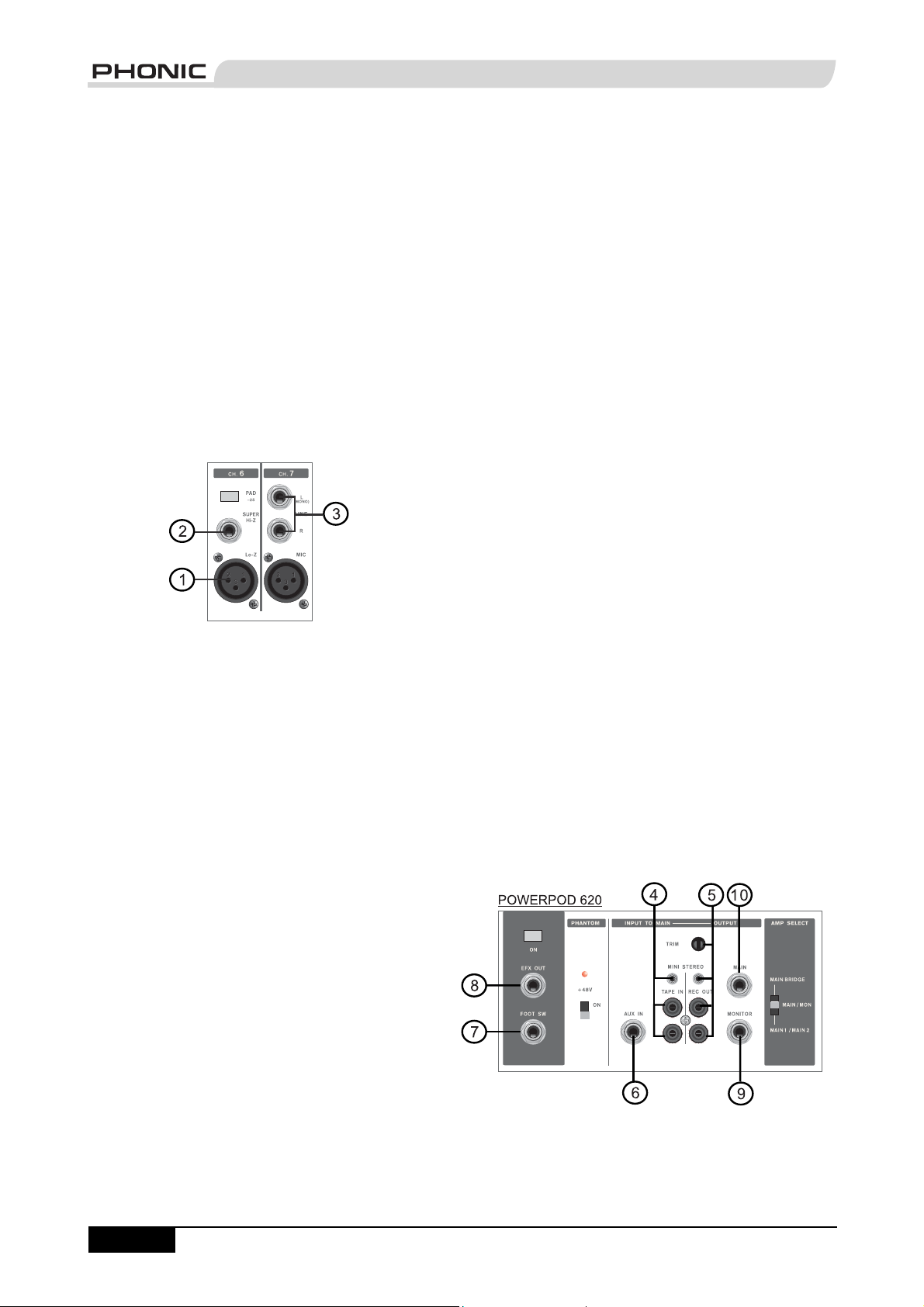
3. Stereo Channel Inputs
Each of the Powerpod 740, 1060 and 1062 Deluxe
Powered Mixers provide 3 stereo input channels (the
Powerpod 620 Deluxe has 2), the inputs of which differ
slightly to the mono channels. The 3-pin XLR inputs
featured are for the addition of microphones with typical
XLR male inputs, where the 2 Line 1/4" TS jacks are for
the addition of various stereo line level input devices,
such as keyboards. If you wish to use a monaural device
on a stereo return input, simply plug the device’s 1/4"
phone jack into the left (mono) stereo input and leave the
right input bare. The signal will be duplicated to the right
due to the miracle of jack normalizing.
Master Section
4. Tape In (L and R)
The fi rst of these inputs accommodates RCA cables
from such devices as tape and CD players. In addition
to these inputs, however, Phonic has incorporated a mini
stereo jack for the inclusion of such devices as mini disc
(MD), portable CD, and MP3 players (such as the Apple
iPod), as well as laptop computers. The line from this
feed is directed to the Tape In mixing bus, before being
fed through to the Main L/R mixing bus.
5. Record Outputs (L and R)
As with the T ape In ports, these outputs will accommodate
RCA cables, able to be fed to a variety of recording
devices. Also, similar to the Tape In ports, included are
mini stereo jacks for the addition of recording devices
such as MD players and laptop computers. A trim control
is featured on these outputs to accommodate for devices
with different recording levels.
2. 1/4" Hi-Z and Super Hi-Z Input Jacks
These inputs accept typical 1/4” TRS or TS unbalanced
inputs. The Hi-Z inputs accept balanced TRS inputs,
and are for Microphone to line-level device (such as
synthesizers and drum machines), where the Super Hi-Z
inputs accept TS unbalanced sources, and can be used
in conjunction with devices with higher impedance levels
(including electric guitars and basses).
NB. When using a line-level device on your mixer, the PAD -25 button
should be initiated.
page 6
POWERPOD User's Manual PHONIC CORPORATION
Page 8
6. AUX Inputs
These TS inputs (which are mono inputs on the
Powerpods 620 and 740 Deluxe, stereo inputs on the
Powerpods 1060 and 1062 Deluxe) connect the mixer
with parallel external devices, such as sub mixers or
external effect processors, receiving the processed
signal from another source and feeding it to the AUX
mixing buses. The stereo AUX inputs (featured on the
Powerpods 1060 and 1062 Deluxe only) can be used
as monaural inputs by simply plugging the device’s 1/4"
phone jack into the left (mono) stereo input and leave the
right input bare. Your good friend, Jack Normalizing, will
take care of the rest.
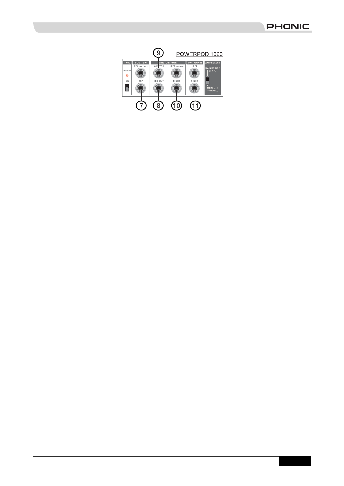
7. Foot Switch Jacks
These ports are for the inclusion of a non-latch foot
switch, used to remotely adjust properties of the built-in
Digital Effect processor. The Powerpods 620 and 740
Deluxe feature a single foot switch jack, which allows the
user to remotely turn on and off the digital effects. The
Powerpods 1060 and 1062 Deluxe, on the other hand,
feature 2 foot switch jacks, the lower of which jack is
used to adjust the tap delay properties, and the upper is
used for the turning digital effects on and off.
8. EFX (Effect) Outputs
These 1/4" TS outputs are the fi nal output from the EFX
send mixing bus. This feed may be used to connect to an
external digital effect processor, or even to an amplifi er
and speakers, depending on your desired settings.
9. Monitor Outputs
These 1/4" TS outputs are the fi nal output from the
Monitor send mixing bus. This feed may be used to
connect to an amplifi er and speaker. Feeding the output
from the Monitor out to an amplifi er (and possibly an
equalizer) and then to a fl oor monitor speaker allows
artists to monitor their own instruments or vocals whilst
performing, or an engineer to monitor the mix.
10. Main Outputs
These jacks will output the fi nal stereo line level signal
sent from the main mixing bus. The primary purpose of
these jacks is to send the Main output to external devices
that may run in parallel with the mixer. This may include
additional power amplifi ers, mixers, PA systems, as well
as a wide range of other possible signal processors.
The Powerpods 620 and 740 Deluxe both feature a
monaural main outputs, where the Powerpods 1060 and
1062 both feature stereo main output jacks.
11. Power Amp Inputs
(Powerpods 1060 and 1062 Deluxe Only)
These inputs support 1/4" TS plugs and can be used for
the inclusion of an external line level stereo signals to
the built-in power amplifi er. If a device is connected to
the power amp inputs, the main feed will automatically
bypass the power amp and the inserted feed will be
amplifi ed and sent to the Speaker Outputs instead.
PHONIC CORPORATION POWERPOD User's Manual
page 7
Page 9
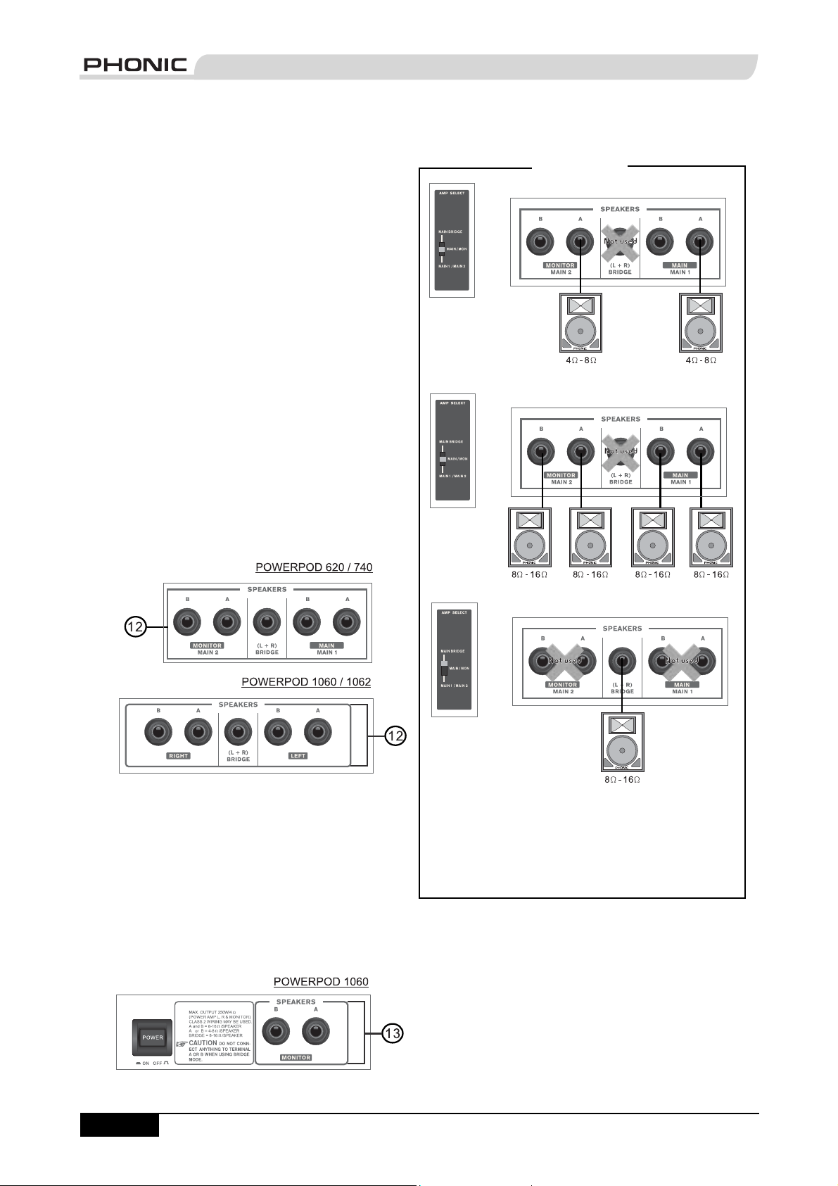
Rear Panel
12. Speaker Outputs
These jacks are used to connect to speakers, fed from
the internal power amp. On all models, they consist of
1/4" Phone Jacks. The Amp Select switch determines
the operation of these jacks. If the Amp Select switch
is set to "Main L-R (Stereo)" or "Main / Moni" - or "Main
1 / Main 2" on the Powerpods 620 and 740 Deluxe - a
single speaker with a 4 to 8 ohm load can be connected
to jack A on both the left and right - or Main 1 and Main 2
- Speaker Outputs, or two speakers with a load between
8 and 16 ohms can be connected to both jacks A and B
of the left and right (Main 1 / 2) Speaker Outputs. When
using Bridge Mono mode, use the Speaker Output
labeled "(L+R) Bridge" only to connect a Speaker with a
loading between 8 and 16 ohms. Refer to the Speaker
set up chart to the right for a more detailed indication of
how to connect speakers.
NB. Due to the fact that the signal has been processed by the power
amp, these ports should be used in conjunction with passive
speakers only to avoid damaging any other equipment.
Speaker Set Up
13. Monitor Speaker Outputs
(Powerpod 1060 Deluxe only)
These 1/4" Phone Jacks are used to connect to
speakers for monitoring purposes, fed from the internal
power amp. These Monitor Speaker Jacks are featured
on the Powerpod 1060 Deluxe only.
NB. Due to the fact that the signal has been processed by the power
amp, these ports should be used in conjunction with passive
speakers only to avoid damaging any other equipment.
page 8
POWERPOD User's Manual PHONIC CORPORATION
Using speakers with an incorrect loading can not only
cause distortion, but also irreversible damage to the
powered mixer. Please ensure the loadings of your
speakers are consistent with those shown above.
Page 10

CONTROLS AND SETTINGS
Channel Controls
Rear Panel
14. Power Button and AC Connector
The power button, located on the rear of the Box Mixer,
is used to activate the mixer. Of course, there’s no point
in activating the mixer if there’s no power, therefore an
AC connector has been included to ensure your Mixer
gets the power it needs. Please use the power cable
that is included with this mixer only.
NB. Before connecting the AC cable to the Powerpod Mixer, please
ensure the local voltage levels are identical to those chosen by the
Voltage Selector switch.
15. Voltage Selector
This switch allows you to select from 2 mains power
modes, 115 VAC / 60 Hz (Allowing you to use the
device in Countries with voltages between 100V and
120V) or 230 VAC / 50 Hz (Allowing you to use the
device in Countries with voltages between 220V and
240V). To change the Voltage Selector, you must fi rst
unscrew and remove the plastic cover that protects
the switch. After changing the Voltage, please replace
the plastic cover to ensure the voltage level is not
inadvertently altered.
NB. Using incorrect voltages can cause irreversible damage to the
mixer. All care must be taken in selecting the voltage appropriate to
your zone. If unsure of local voltage levels, contact a knowledgeable
source before using this mixer.
16. HIGH (High Frequency) Control
This control is used to give a shelving
boost or cut of ±15 dB to high
frequency (12 kHz) sounds. This will
adjust the amount of treble included
in the audio of the channel, adding
strength and crispness to sounds such
as guitars, cymbals, synthesizers and
Michael Jackson.
17. MID (Middle Frequency) Control
(Powerpods 740, 1060 and 1062
Deluxe only)
This control is used to provide a
peaking style of boost and cut to the
level of middle frequency sounds
at a range of
middle frequencies of an audio feed
can be rather diffi cult when used in a
professional audio mix, as it is usually
more desirable to cut middle frequency
sounds rather than boost them, soothing overly harsh
vocal and instrument sounds in the audio.
18. LOW (Low Frequency) Control
This control is used to give a shelving
boost or cut of
(80 Hz) sounds. This will adjust the
amount of bass included in the audio
of the channel, and bring more warmth
and punch to drums, bass guitars and
Isaac Hayes.
±15 dB. Changing
±15 dB to low frequency
19. MON (Monitor) Level Control
This control alters the signal level
that is being sent to the Monitor
mixing buses, the signal of which is
suitable for connecting stage monitors,
allowing artists to listen to the music
that is being playing.
20. EFX (Effect) Level Control
This control alters the signal level
PHONIC CORPORATION POWERPOD User's Manual
page 9
Page 11

that is sent to the EFX output, which can be used in
conjunction with external signal processors (this signal
of which can be returned to mixer via the stereo return
inputs), or simply as additional auxiliary outputs for any
means required. These controls also adjust the level of
audio that is sent to the built-in digital effect panel.
21. PAN/BAL Control
(Powerpods 1060 and 1062 Deluxe only)
This alternates the degree or level of audio that the left
and right side of the main mix should receive. On mono
channels, this control will adjust the level that the left
and right should receive, where as on a stereo channel,
adjusting the BAL control will attenuate the left or right
audio signals accordingly.
22. Channel Level Control
This control will alter the signal level that is sent from the
corresponding channel to the Main mixing bus.
23. PAD -25 Button
The PAD -25 button, located above the 1/4” Phone Jack
of mono channels, is used to attenuate the input signal
by 25 dB. This should only be pushed in when using linelevel input devices.
Digital Effect Processor
24. Digital Effect Display
This panel displays the titles of different effects that can
be added to audio. When
you select the effect, the
LED by the effect name will
illuminate (on the Powerpod
620 Deluxe the effect
number is simply selected
by using the Program Control
- no LED indicators required),
and the alteration be applied
automatically. For a list of
available effects, please
observe the Digital Effect
Table.
shown on the Digital Effect Display. Turning the control
will automatically change the effect and apply it to the
mix. To see the list of available programs, please check
the Digital Effect Table.
26. Parameter Control
(Powerpods 1060 and 1062 Deluxe only)
This will adjust the one main parameter of the digital
effect that is currently applied to the audio feed. Please
refer to the Digital Effects Table for more information on
Effect parameters.
27. Tap Delay Button and Indicator
(Powerpods 1060 and 1062 Deluxe only)
When the tap delay effect is selected, this button is used
to determine the delay time. By pushing the button
several times, the mixer interprets the time between
last two pushes and remembers this as the delay time
until the button is pushed again; even after the power
is turned off. When the tap delay effect is selected, the
corresponding LED will fl ash at the intervals selected.
The delay time can also be determined through use of
a foot switch.
28. Peak Indicator
(Powerpods 1060 and 1062 Deluxe only)
This LED indicator will illuminate when the Digital Effect
Processor overloads. It is best to adjust the DSP Effect
Fader so as to ensure the PEAK indicator does not light
up. This will ensure a greater quality of audio.
29. Effect On Button and Indicator
This button is pushed to turn the corresponding effect
panel on or off. When the effect processor is turned on,
the corresponding LED illuminates.
Master Section
page 10
25. Program Control
This control is used to scroll
through the various effects
POWERPOD User's Manual PHONIC CORPORATION
Page 12

30. EFX To Monitor Control)
This controls the level of the processed signal from
the built-in effect processor, that is sent to the Monitor
mixing bus.
31. EFX To Main Control
This controls the level of the processed signal from the
built-in effect processor, that is sent to the Main L/R
mixing bus.
32. AUX In Controls
The Powerpods 620 and 740
Deluxe feature a single AUX
in control (located beneath the
Main Equalizer) that adjusts the
fi nal level of the AUX in input
that is sent to the Main mixing
bus. The Powerpods 1060 and
1062 Deluxe, on the other hand,
feature 2 AUX in Controls. One
that adjusts the fi nal level that is
sent to the Monitor mixing bus
(the upper control), another that controls the fi nal
level that is sent to the Main L-R mixing bus (the lower
control).
33. Tape In
The Powerpod 620 Deluxe features a single Tape in
control (located below the equalizer) that adjusts the
fi nal level of the AUX in input that is sent to the Main
mixing bus. The Powerpods 740, 1060 and 1062
Deluxe, on the other hand, feature 2 Tape in controls.
One that adjusts the fi nal level that is sent to the
Monitor mixing bus (the upper control), another that
controls the fi nal level that is sent to the Main mixing
bus (the lower control).
34. Graphic Equalizers
These graphic equalizer allows you to adjust the
frequency response of a signal, with a maximum of
dB of signal boost or cut for each of the frequencies.
The Powepods 740, 1060 and 1062 Deluxe each
feature dual Graphic Equalizers, with models 1060
and 1062 feature two 10-band equalizers and the
740 feature two 7-band equalizers. The Powerpod
620 features a single stereo 7-band equalizer for
both the Main and Monitor signals. The uppermost
equalizer is for alteration of the Monitor signal (when
the EQ switch is in the appropriate position it becomes
the Main Left EQ - on the Powerpods 1060 and 1062
- and the Main 2 EQ - on the Powerpod 740), where
the lower equalizer is for the Main L-R signal (or Main
Right signal on Powerpods 1060 and 1062, Main 2 on
Powerpod 740).
35. EQ IN and Indicator
(Powerpods 740, 1060 and 1062 Deluxe only)
This button activates the graphic equalizer in which
it accompanies. The corresponding LED indicator
illuminates when the EQ is activated.
±12
PHONIC CORPORATION POWERPOD User's Manual
page 11
Page 13

36. EQ Select Switch
(Powerpods 740, 1060 and 1062 Deluxe only)
This switch (featured on the Powerpods 740, 1060
and 1062 Deluxe only) enables you to select the way
you utilize the pair of Equalizers on these models.
On models 1060 and 1062, when the switch is in
the uppermost position it enables you to use the
top equalizer for the Monitor signal, and the bottom
equalizer for the Main L/R signal; the lower position
enables the equalizers to be used for the Main Left
and Right signals. On the 740 model, however, the
uppermost position is identical as the 1060 and 1062;
however the lower position allows the equalizers to be
used for the mixer’s Main 1 and 2 signals.
39. Amp Select Switches
This switches control the activity of the built-in power
amp, enabling the user to alternate between the
different signals which can be processed by the builtin power amp and routed to the speaker outputs on
the rear of the device. This switch allows you to select
from: Main/Monitor – taking the monitor and main
signals and directing them to the appropriate speaker
outputs – Main L / Main R – using the Main L/R signal
to feed the speaker outputs – and Main Bridge – which
combines the Main Left and Right signal and feeds
them through the (L+R) Bridge output.
NB. When using a mono bridge connection, do not connect a
speaker to any of the Main/Monitor A or B jacks, located on the
rear of the mixer. Use the "(L+R) Bridge" speaker jack only.
37. Rumble Filter
(Powerpods 740, 1060 and 1062 Deluxe only)
This button enables a high-pass fi lter on channels 1
through to 6 of the Mixer (channels 1 through 4 on the
Powerpod 740 Deluxe), effectively removing stage
rumble from your audio signal.
38. Phantom Power Switch and Indicator
When this switch is in the on position it activates
+48V of Phantom Power for all XLR jacks of all
channels on the Powerpod Mixers, allowing condenser
microphones to be used on these channels. The
corresponding LED will illuminate when the Master
Phantom Power is activated.
40. Monitor Level Control
This rotary control allows the user to adjust the fi nal
signal level sent to all Monitor outputs.
41. Main Level Control
This rotary control allows the user to adjust the
fi nal signal level sent to the Main L-R and Speaker
outputs.
page 12
POWERPOD User's Manual PHONIC CORPORATION
Page 14

42. Level Meter
These level meters give
accurate indications of when
audio levels of the Main L/R
stereo (or Main mono) and
Monitor outputs reach certain
levels. The 0 dB indicator
illuminates is approximately
equal to an output level of +4
dBu. It is suggested for the
maximum use of audio to set
the various levels controls so
that it sits steadily between
0 and the second highest
level indicated on the Level
Meter to make full use of
audio, while still maintaining
fantastic clarity. The 620
Deluxe features a single dual 5-segment LED display,
the 740 Deluxe features a two single 5-segment LED
displays (for monitor and main signals), and the 1060
and 1062 both feature a single 5-segment Monitor LED
level display and a dual 5-segment Main LED level
display.
43. Limiters
(Powerpods 740, 1060 and 1062 Deluxe only)
These LED indicators illuminate when the power
amplifi er’s built-in limiters are activated, which effectively
reduce signal levels when they reach high levels that
could prove to damage sound quality.
44. Power Indicator
This LED indicator illuminates when power of your
Powerpod Mixer is activated.
PHONIC CORPORATION POWERPOD User's Manual
page 13
Page 15

APPLICATION
Powerpod 620
page 14
POWERPOD User's Manual PHONIC CORPORATION
Page 16

Powerpod 1060
PHONIC CORPORATION POWERPOD User's Manual
page 15
Page 17

DIGITAL EFFECT TABLES
Powerpod 620 Deluxe Effects
No. Program Name Program Description
1 VOCAL 1 Ideal for Echo and Reverb of vocals
2 VOCAL 2 Ideal for Echo and Reverb of vocals
3 ECHO 1 Ideal for Echoing vocals
4 ECHO 2 Ideal for Echoing vocals
5 S. HALL Ideal for mimicking the acoustics of a Small Hall
6 L. HALL Ideal for mimicking the acoustics of a Large Hall
7 ROOM Creates acoustics similar to those of a Small Room
8 PLATE Simulates a Plate Reverb device, creating hard sounding Reverberation
Powerpod 740 Deluxe Effects
Program Name Program Description
VOCAL 1 Ideal for Echo and Reverb of vocals
VOCAL 2 Ideal for Echo and Reverb of vocals
VOCAL 3 Ideal for Echo and Reverb of vocals
ECHO 1 Ideal for Echoing vocals
ECHO 2 Ideal for Echoing vocals
S. HALL Ideal for mimicking the acoustics of a Small Hall
M. HALL Ideal for mimicking the acoustics of a Medium Hall
L. HALL Ideal for mimicking the acoustics of a Large Hall
CATH.
ROOM 1 Creates acoustics similar to those of a Small Room
ROOM 2 Creates acoustics similar to those of a Medium Room
PLATE 1 Simulates a Plate Reverb device, creating hard sounding Reverberation
PLATE 2 Simulates a Plate Reverb device, creating hard sounding Reverberation
GATE REVERB Produces effect by cutting the reverberation
FLANGE Adds a sense of pitch to the sound
Creates acoustics similar to those of a Cathedral
page 16
POWERPOD User's Manual PHONIC CORPORATION
Page 18

Powerpod 1060 and 1062 Deluxe Effects
Parameter Controllability
Program Name Program Description
HALL Ideal for mimicking the acoustics of a Hall Reverb Time 0.3 sec – 10 sec
ROOM Creates acoustics similar to those of a Small Room Reverb Time 0.3 sec – 3.2 sec
PLATE
VOCAL 1 Ideal for Reverb of vocals Reverb Time 0.3 sec – 10.0 sec
VOCAL 2 Ideal for Reverb of vocals Reverb Time 0.3 sec – 10.0 sec
ECHO 1 Ideal for Echoing vocals Delay Time 0 – 800 ms
ECHO 2 Ideal for Echoing vocals Delay Time 0 – 800 ms
DELAY 1 Delays the audio signal Delay Time 0 – 800 ms
DELAY 2 Delays the audio signal Delay Time 0 – 800 ms
EARLY REF.
GATE REVERB Produces effect by cutting the reverberation Room Size 0.1 – 5.0
DOUBLER Creates an effect simulating 2 vocalists Pitch Fine 0 – 50
SYMPHONIC Adds richly layered depth to the sound Depth 0 – 100%
FLANGE Adds a sense of pitch to the sound
DISTORTION Used to distort the sound Drive 0 – 100%
TAP DELAY
Simulates a Plate Reverb device, creating hard sounding Reverberation
Modifi es early refl ections, creating a deeper sound or an
echo-like effect
Allows you to select the delay time by clicking a button
twice or by use of a footswitch. The amount of feedback
is adjusted using the PARAMETER control.
Parameter Variable Range
Reverb Time 0.3 sec – 10.0 sec
Room Size 0.1 – 10.0
Modulation
Frequency
Feedback Gain 0 – 99%
Delay Time
0.05 – 4.00 Hz
100 ms (600 bpm)
– 2690 ms (22.3 bpm)
PHONIC CORPORATION POWERPOD User's Manual
page 17
Page 19

SPECIFICATIONS
Powerpod 620
Deluxe
POWER AMP, output
power in watts
@THD<0.5%, 1KHz
Number of Power
channels
Limiter 2 2 3 2
8 ohms per channel 80 145 165 245
4 ohms per channel 120 220 250 375
8 ohms bridge mono 240 440 500 750
Inputs
Lo-Z / Hi-Z channels 4, 2 with super Hi-Z
Balanced Mic/ Line-Level
channels
2T input 1x Mini Stereo & 2x
Aux returns 1 x 1/4” TS, Unbal. 1 x 1/4” TS, Unbal. 2 x 1/4” TS (Stereo) 2 x 1/4” TS (Stereo)
Outputs
Main out 1x 1/4” TS, Unbal. 1x 1/4” TS, Unbal. 2 x 1/4” TS (Stereo),
Monitor out 1 x 1/4” TS, Unbal. 1 x 1/4” TS, Unbal. 1 x 1/4” TS, Unbal. 1 x 1/4” TS, Unbal.
Efx send 1 x 1/4” TS, Unbal. 1 x 1/4” TS, Unbal. 1 x 1/4” TS, Unbal. 1 x 1/4” TS, Unbal.
REC out A Pair, RCA & Mini
Speaker outputs 5 x 1/4” TS 5 x 1/4” TS 7 x 1/4” TS 5 x 1/4” TS
Channel Strips 6 7 9 9
Monitor / Effect send
controls
Pan/Balance control N/A N/A Y Y
Volume Controls Rotary Rotary Rotary Rotary
Pad in/out CH 1~4 CH 1~4 CH 1~6 CH 1~6
Master Section
Aux returns 1, Mono 1, Mono 1, Stereo 1, Stereo
Effects Return to Monitor Yes Yes Yes Yes
Faders Moni, Main (Rotary) Monitor, Main (Rotary) Monitor, Main L/R
Metering
Number of channels 2 2 3 3
Segments 5 5 5 5
Phantom Power Supply +48V DC +48V DC +48V DC +48V DC
Switches Global Global Global Global
Digital Effect Processor 8 preset programs
22 3 2
(470K ohms)
23 3 3
RCA
Stereo
22 2 2
(24-bit) with foot
switch
(effect on / off)
Powerpod 740 Deluxe Powerpod 1060
4, 2 with super Hi-Z
(470K ohms)
1x Mini Stereo & 2x
RCA
A Pair, RCA & Mini-
Stereo
16 preset programs
(24-bit) with foot switch
(effect on/off)
Deluxe
6, 2 with super Hi-Z
(470K ohms)
1x Mini Stereo & 2x
RCA
Unbal.
A Pair, RCA & Mini-
Stereo
(Rotary)
16 effects with one
main parameter control,
tap delay control, foot
switch
(effect on / off, tap)
Powerpod 1062
Deluxe
6, 2 with super Hi-Z
(470K ohms)
1x Mini Stereo & 2x
RCA
2 x 1/4” TS (Stereo),
Unbal.
A Pair, RCA & Mini-
Stereo
Monitor, Main L/R
(Rotary)
16 effects with one
main parameter control,
tap delay control, foot
switch
(effect on / off, tap)
page 18
POWERPOD User's Manual PHONIC CORPORATION
Page 20

Graphic EQ Stereo 7-band 2 x 7-band (assignable
Center Frequency 60, 120, 360, 1K,
Range ±12 dB ±12 dB ±12 dB ±12 dB
Noise: 20Hz to 20KHz
bandwidth, IHF-A
weighted, line inputs
to main L/R outputs,
all channels assigned,
panned L/R
Master output, all fader
down
Power amp output, all
fader down
THD
Power output, 1KHz,
20Hz to 20KHz
Any output, 1KHz @
+14dBu, 20Hz to 20KHz,
channel inputs
CMRR (1 KHz @ -60dBu,
Gain at maximum)
Crosstalk (1KHz @
0dBu, 20Hz to 20KHz
bandwidth, channel in
to main L/R outputs)
Channel fader down,
other channels at unity
Channel muted, other
channels at unity
Frequency Response
(Mic input to output)
20Hz ~ 20KHz, line level
o/p @ +4dBu into 600
ohms
20Hz ~ 20KHz, power
amp o/p 1 watt into 8
ohms
Maximum Level
Mic preamp input +10 dBu +10 dBu +10 dBu +10 dBu
All other inputs +22 dBu +22 dBu +22 dBu +22 dBu
Unbalanced output +22 dBu +22 dBu +22 dBu +22 dBu
Impedance
Lo-Z input (Mic in) 2.2K ohms 2.2K ohms 2.2K ohms 2.2K ohms
Hi-Z input (Line in) 5K ohms 5K ohms 5K ohms 5K ohms
Super Hi-Z (Line in) 470K ohms 470K ohms 470K ohms 470K ohms
All other input >10K ohms >10K ohms >10K ohms >10K ohms
RCA 2T output 1.2K ohms 1.2K ohms 1.2K ohms 1.2K ohms
All other outputs 560 ohms 560 ohms 560 ohms 560 ohms
Equalization 3-band, ±15 dB 3-band, ±15dB 3-band, ±15dB 3-band, ±15dB
Low EQ 80 Hz 80 Hz 80 Hz 80 Hz
2.5K, 7K, 16 KHz
<-78 dBu <-78 dBu <-78 dBu <-78 dBu
<-63 dBu <-63 dBu <-63 dBu <-63 dBu
@60 Watts, 4 ohms
<0.5%
<0.3% <0.3% <0.3% <0.3%
80 dB 80 dB 80 dB 80 dB
<-63 dB <-63 dB <-63 dB <-63 dB
<-64 dB <-64 dB <-64 dB <-64 dB
+0/-2 dB +0/-2 dB +0/-2 dB +0/-2 dB
+0/-2 dB +0/-2 dB +0/-2 dB +0/-2 dB
to Main 1 / Main 2)
60, 120, 360, 1K, 2.5K,
7K, 16K Hz
@110 Watts, 4 ohms
<0.5%
ST+1 (assignable to
main L & R), 10-band
40, 80, 160, 315, 630,
1.25K, 2.5K, 5K, 10K,
16K Hz
@125 Watts, 4 ohms
<0.5%
ST+1 (assignable to
main L & R), 10-band
40, 80, 160, 315, 630,
1.25K, 2.5K, 5K, 10K,
16K Hz
@187.5 Watts, 4 ohms
<0.5%
PHONIC CORPORATION POWERPOD User's Manual
page 19
Page 21

Mid EQ N/A 2.5 KHz 2.5 KHz 2.5 KHz
Hi EQ 12 KHz 12 KHz 12 KHz 12 KHz
Rumble fi lter N/A 75 Hz, 18 dB/oct 75 Hz, 18 dB/oct 75 Hz, 18 dB/oct
Foot switch Digital effect mute:
Microphone Preamp
E.I.N.
150 ohms terminated,
max gain
Power Consumption
(Average Maximum)
Power Requirement Switchable between
ON/OFF
<-122 dBm <-122 dBm <-122 dBm <-122 dBm
120 Watts 220 Watts 375 Watts 375 Watts
115 VAC and 230
VAC, 50/60 Hz
Digital effect mute:
ON/OFF
Switchable between
115/230 VAC, 50/60 Hz
Digital effect mute:
ON/OFF
Switchable between
115/230 VAC, 50/60 Hz
Digital effect mute:
ON/OFF
Switchable between
115/230 VAC, 50/60 Hz
page 20
POWERPOD User's Manual PHONIC CORPORATION
Page 22

DIMENSIONS
POWERPOD 620 POWERPOD 740 POWERPOD 1060 POWERPOD 1062
A 440 mm (17.3 inches) 471 mm (18.5 inches) 471 mm (18.5 inches) 471 mm (18.5 inches)
B 245 mm (9.6 inches) 265 mm (10.4 inches) 285 mm (11.2 inches) 285 mm (11.2 inches)
C 275 mm (10.8 inches) 275 mm (10.8 inches) 275 mm (10.8 inches) 275 mm (10.8 inches)
WEIGHT
POWERPOD 620 12.5 kg (27.5 lbs)
POWERPOD 740 13.5 kg (29.7 lbs)
POWERPOD 1060 14 kg (30.8 lbs)
POWERPOD 1062 14 kg (30.8 lbs)
PHONIC CORPORATION POWERPOD User's Manual
page 21
Page 23

POWERPOD 620 BLOCK DIAGRAM
B
TAPE/IN
2
MAIN
EFFECT
MONI
LOW-Z
LINE1
LINE2
MINI STEREO
1
AUX/IN
TAPE IN_LEVEL
AUX IN_LEVEL
SUM
+
LOW
EQ
HIGH
MONITO R
EFFECT
+48V
PHAN TOM
HA
CHANN EL5-6
LOW
HIGH
LEVEL
LOW-Z
SUPER HI-Z
HA
+
PAD SW .
PHAN TOM
+48V
CHANN EL3-4
EQ
LEVEL
MONITO R
EFFECT
LOW
HIGH
LOW-Z
PHAN TOM
Hi-Z
PAD SW .
+48V
HA
CHANN EL1-2
EQ
LEVEL
MONITO R
EFFECT
M
AIN
EFF
ECT
MONI
DRIVE
TO MONITO R
115/230VAC 50/60Hz
D.S. P
Program
+v
POW ER SUPPLY
SW ITCHING
Echo on/off
PA2
DISPLAY
EFFECT OUT
FOO T SW
MONITO R OUT
MONI SPK
B
A
TO MAIN
MASTER
MASTER
MON
60
DUAL G.EQ
120
7K
16K
MONI
MAIN+
MAIN-
BRI G.SPK.
MAIN
MINI STER EO
REC OUT
MAIN BRI DGE
MAIN1 MAIN2
MAIN MONITO R
PA1
MAIN SPK.
MAIN OUT
A
DISPLAY
page 22
POWERPOD User's Manual PHONIC CORPORATION
Page 24

POWERPOD 740 BLOCK DIAGRAM
PHONIC CORPORATION POWERPOD User's Manual
page 23
Page 25

POWERPOD 1060 BLOCK DIAGRAM
page 24
POWERPOD User's Manual PHONIC CORPORATION
Page 26

POWERPOD 1062 BLOCK DIAGRAM
C
H1_6
CH1_6 R
CH1_6 MON
EFX
MON
MAIN
MAIN
TAPE IN
R
LEVE L
MON
AUX_IN
L
(MONO) L
R
LEVE L
MON
L
L
R
HPF
ON/OFF
Peak
PROGRAM
DIGITAL ECHO
PARAMETER
TO MAIN
TO MON
TAP DELAY
CH1_6
RUMBLE
L (MONO)
R
TON E
LEVE L
BAL
EFX
-10~+10dB
Lo-Z
HA
HIGH
MID
LOW
MON
TON E
LEVE L
BAL
10-BAND GEQ
10K 16K8040
~
~
SUPER Hi-Z
PAD (-25)
HA
HIGH
CHANNEL7,8, 9
TON E
MID
LOW
MON
LEVE L
EFX
R
10-BAND GEQ
40
10K80
~
~
Hi_Z
Lo-Z
HIGH
CHANNEL5,6
MID
LOW
MON
PAN
L
10-BAND GEQ
EFX
Lo-Z
PHANTOM
PAD (-25)
HA
+48V
CHANNEL1_4
TON E
LEVE L
PAN
L
R
CH1_6 L
CH1_6 R
CH1_6 MON
EFX
N
MO
MAIN L
MAIN R
HPF
HPF
RUMBLE
CH1~6
16K
EQ I N
L
R
L
R DISPLAY
L DISPLAY
TAP
EFX OUT
FOO T SW
R
MAIN LEVEL
R
REC OUT
MAIN/MON
MAIN OUT
LI MITER
AMP SELECT
L (MONO)
AMP
AMP IN/R
SPK_R B
SPK_R A
RIGHT
STEREO
AMP IN/L
BRIDGE
MAIN/MON
LEFT/RIGHT
MAIN/BRIDGE
PROTECTOR
AMP
SPK_L B
SPK_L A
LEFT
EQ I N
MON LEVEL
DISPLAY
MON OUT
LI MITER
PHONIC CORPORATION POWERPOD User's Manual
page 25
Page 27

 Loading...