

LG 40pa15b schematic
- 7 -
1. Application Object
These instructions are applied to all of the PDP monitor, NP00KC.
2. Notes
(1) Because this is not a hot chassis, it is not necessary to use
an isolation transformer. However, the use of isolation
transformer will help protect test instrument.
(2) Adjustment must be done in the correct order.But the
adjustment can be changed by consideration of mass
production.
(3) The adjustment must be performed in the circumstance of
25±5°C of temperature and 65±10% of relative humidity if
there is no specific designation.
(4) The input voltage of the receiver must keep 220V, 60Hz in
adjusting.
(5) The receiver must be operated for about 15 minutes prior
to the adjustment.
¤ After receiving 100% white pattern(06CH), the receiver
must be operate prior to adjustment.(Or white condition
in HEAT-RUN mode)
¤ŁEnter into HEAT-RUN mode
- Select the 2.W/B by pressing ADJ button on Remote
Control for adjustment. And press the VOL + button.
- Press the VOL + button in HEAT-RUN.
(OSD display HEAT-RUN WHITE and screen display
100% full WHITE PATTERN)
[ Set is activated HEAT-RUN without signal generator in
this mode.
[ Single color pattern of HEAT-RUN mode uses to check
PANEL.(RED/BLUE/GREEN)
[Caution] If you turn on a still screen more than 20minutes
(Especially Digital pattern(13 CH), Cross Hatch
pattern(09CH)), a afterimage may be occur in the
black level part of the screen.
Each PCB Assy must be checked by check JIG Set
before assembly.(Especially, be careful Power PCB
Assy which can cause fatal Damage to PDP module.)
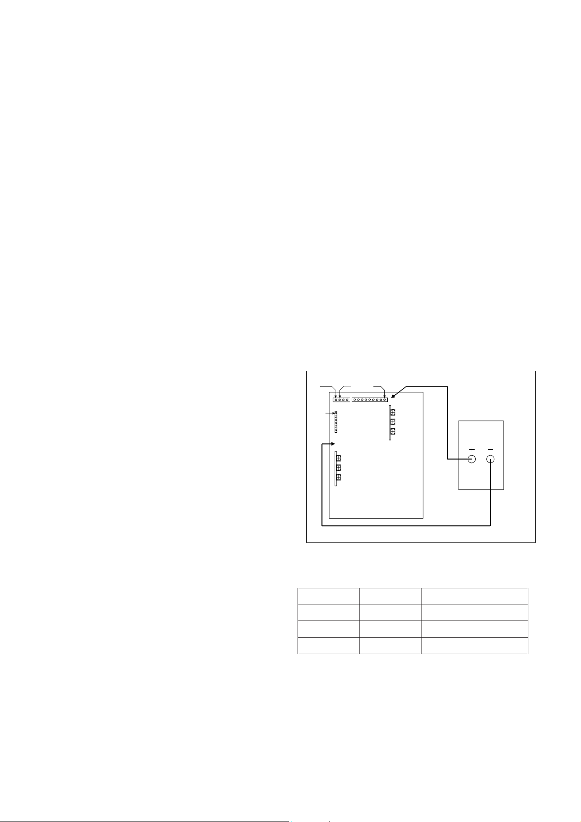
3. POWER PCB Assy Voltage Adjustment
3-1. Test Equipment
D.M.M 1EA
3-2. Connection Diagram for Measuring
Refer to Fig 1.
3-3. Adjustment Method
(1) Va Adjustment
¤ Connect pin 1 of P806 or P811 to (+) jack of D.M.M.
¤ŁAfter turning the VR803(Va Adj), voltage of D.M.M
adjustment as same as Va voltage which on label of
panel right/bottom. (Deviation : ±0.5V)
(2) Vs Adjustment
¤ Connect pin 9 of P803 to (+) jack of D.M.M.((-):GND)
¤ŁAfter turning the VR804(Vs Adj), voltage of D.M.M
adjust as same as Vs voltage which indicated on label
of panel right/bottom. (Deviation : ±0.5V)
(3) Vsc Adjustment
¤ Connect pin 2 of P802 to (+) jack of D.M.M.((-):GND)
¤ŁAfter turning the VR806(VSC Adj), voltage of D.M.M
adjust as same as Vsc voltage which indicated on label
of panel right/bottom. (Deviation : ±0.5V)
(4) Vsetup Adjustment
¤ Connect pin 1 of P802 to (+) jack of D.M.M.((-):GND)
¤ŁAfter turning the VR805(Vsetup Adj),voltage of D.M.M
adjust as same as Vsetup voltage which indicated on
label of panel right/bottom. (Deviation : ±0.5V)
[ Replace PDP module or PCB Board, adjust certainly
Power PCB Assy Voltage.
ADJUSTMENT INSTRUCTIONS
VSETUP
VR806
VR805
VR804
DMM
VSC
VA
VSC CTL
V
A CTL
P806
VR803
GND
V
SETUP CTL
V
S CTL
V
S
P802 P803
<Fig 1> Connection Diagram of Power Adjustment for Measuring
Refer to Typical Voltage
Va
Vs
Vsc
Vsetup
75V
176V
110V
220V
Address Voltage
Sustain Voltage
Scan Voltage
Setuo Voltage

- 8 -
4. Adjustment of Auto RGB
4-1 Synopsis
AUTO RGB adjustment is function to correct the deviation of
RGB and set the optimist Black leveland Gain automatically in
“Analog => Digital transmitter”
4-2 Test Equipment
PC Pattern Generator
(It’s possible output of 16 Gray Scale Pattern. And RGB
output Level exactly set 0.7Vp-p)
4-3 Adjustment Method
(1) Input 16 Gray Scale Pattern signal and select input
selection by RGB.
(2) Select the 2.W/B by pressing ADJ button on Remote
Control for adjustment. And press the VOL + button.
(3) Set HEATRUN OFF and Select AUTO RGB.
Press VOL+ button.
5. Adjustment of White Balance
5-1. Test Equipment
- Color analyzer(CA-100 or same production)
- AV Pattern generator
- Auto adjstment generator ( It is necessary while Auto
adjustment,communicate by RS-232C)
5-2. Connection Diagram of Equipment for
Measuring
[ After stop the Micom by pressing IN-START Key on Remote
Control, insert the P121with automatic adjustment of
connector.
After remove connector, move the Micom by pressing OK Key.
5-3. Adjustment of White Balance
• Operate the Zero-calibration of the CA-100, then stick
sensor to PDP module surface when you adjust.
• For manual adjustment, it is also possible by the following
sequence.
(1) Select WHITE PATTERN of HEAT RUN mode by pressing
ADJ button on Remote Control for adjustment then operate
HEAT RUN more than 15 minute.
(2) Supply Full White Signal in AV pattern generator. (External
Input)
(3) Select DYNAMIC to PSM.
(4) To adjust White Balance,stick sensor to center of screen.
Select the W/B by pressing ADJ button on Remote Control
for adjustment. And press the VOL + button for adjustment
mode.Becomes X=0.295±0.003, Y=0.305±0.003 and color
temperature becomes 8.000
cK ± 500cK by pressing VOL+,
- button. (G-ADJ fixation)
(5) Exit adjustment mode using OK button.
- 9 -
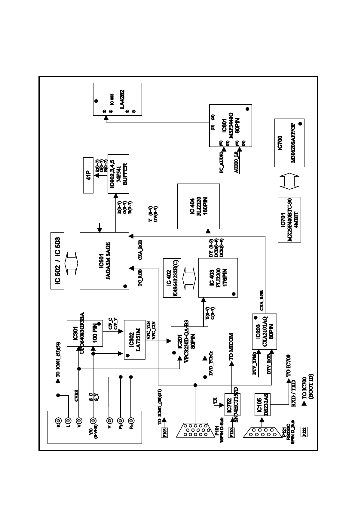
BLOCK DIAGRAM
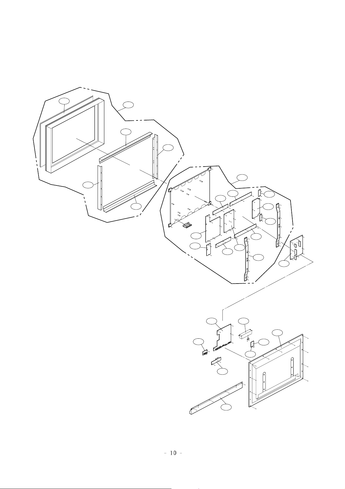
EXPLODED VIEW
300
301
303
304
305
302
200
202
201
203
204
205
207
211
210
206
209
208
400
540
401
550
551
530
570
520
560
EXPLODED VIEW PARTS LIST
200 6348Q-A032D PDP,40” 4:3 640*480 FOR DND INTERC
201 6871VSN168A PCB ASSEMBLY,SUB PDP 6871QRH007A X RIGHT TO
202 6871VSN168B PCB ASSEMBLY,SUB PDP 6871QLH009A X LEFT TOP
203 6871VSN168C PCB ASSEMBLY,SUB PDP 6871QTH012A ZCNT TOP
204 6871VSN168D PCB ASSEMBLY,SUB PDP 6871QZH007A ZSUS B/D
205 6871VSN168E PCB ASSEMBLY,SUB PDP 6871QTH013A ZCNT BOTTO
206 6871VSN168F PCB ASSEMBLY,SUB PDP 6871QLH010A X LEFT BOT
207 6871VSN168G PCB ASSEMBLY,SUB PDP 6871QRH008A X RIGHT BO
208 6871VSN168H PCB ASSEMBLY,SUB PDP 6871QDH015A YDRV B/D
209 6871VSN168J PCB ASSEMBLY,SUB PDP 6871QYH012A YSUS B/D
210 6871VSN168K PCB ASSEMBLY,SUB PDP 6871QCP005A CTRL B/D
211 4980V00164B SUPPORTER,VERTICAL
212 4980V00164C SUPPORTER,VERTICAL
300 3091V00288E CABINET ASSEMBLY,LG FLATRON PLASMA
3091V00288C CABINET ASSEMBLY *MU-40PA15
301 4980V00183A SUPPORTER FITER ASSY,TOP PD-40X3
302 4980V00180A SUPPORTER FILTER ASSY,BOM
303 4980V00181A SUPPORTER FILTER ASSY,SIDE
305 3790V00266B WINDOW,H04PR-LGE40-02 MN-40PA10 FIBER
400 3809V00212N BACK COVER ASSEMBLY,MU-40PA15B - BLACK
3809V00278J BACK COVER ASSEMBLY *MU-40PA15
401 3301V00005L PLATE ASSEMBLY,A/V 3300V00074 40”PDP BLACK
3301V00005K PLATE ASSEMBLY *MU-40PA15
520 6871VMMC09A PCB ASSEMBLY,MAIN RF-02KB MT-40PA15
530 3501V00028A BOARD ASSY,PDP POWER LINE FILTER PD-40/36
540 6871VSMD83A PCB ASSEMBLY,SUB NP-00KC MU-40PA15 MNT CONT
550 6871VSMD82B PCB ASSEMBLY,SUB PSW NP00KC BLACK POWER SWITCH
6871VSMD82A PCB ASSEMBLY,SUB PSW NP00KC *MU-40PA15
551 5020V00445C BUTTON,MU-40PA10B
5020V00445A BUTTON,MU-40PA15
560 6871VSM910A PCB ASSEMBLY,SUB NF-01DA MN-42PZ10 MNT SPK
570 3501V00027E BOARD ASSEMBLY,PDP POWER MT/MP/MU/MZ-40PA10 M
580 6871VSMD81A PCB ASSEMBLY,SUB A/V NP-00KC AV PACK
No.
Part No.
Description
 Loading...