

Page 1

40LX774H
43LX774H
49LX774H
55LX774H
Lodging Guest Interactive Pro:Centric ® TVs
Commercial Mode Setup Guide
Note: Selected features shown in this guide may not be available on all models.
EXPERIENCED INSTALLER
EZ-Manager Wizard
pages 16 – 25
Custom Master TV Setup
pages 41 – 43
Cloning Procedures
pages 44 – 50
© Copyright 2017 LG Electronics U.S.A., Inc.
P/N: 206-4309 (Rev E)
Page 2
For Customer Support/Service, please call:
1-888-865-3026
The latest product information and documentation is
available online at:
www.lg.com/us/business
MODEL and SERIAL NUMBER
The model and serial numbers of this TV are located on the
back of the cabinet. For future reference, LG suggests that you
record those numbers here:
Model No._________________ Serial No._______________
WARNING
RISK OF ELECTRIC SHOCK
DO NOT OPEN
WARNING:
TO REDUCE THE RISK OF ELECTRIC SHOCK DO NOT REMOVE COVER (OR BACK). NO USERSERVICEABLE PARTS INSIDE. REFER TO QUALIFIED SERVICE PERSONNEL.
The lightning flash with arrowhead symbol, within an equilateral triangle, is intended to alert the user to the
presence of uninsulated “dangerous voltage” within the product’s enclosure that may be of sufficient magnitude
to constitute a risk of electric shock to persons.
The exclamation point within an equilateral triangle is intended to alert the user to the presence of important
operating and maintenance (servicing) instructions in the literature accompanying the appliance.
WARNING:
TO PREVENT FIRE OR SHOCK HAZARDS, DO NOT EXPOSE THIS PRODUCT TO RAIN OR MOISTURE.
WARNING:
This product contains chemicals known to the State of California to cause cancer and birth defects or other
reproductive harm. Wash hands after handling.
POWER CORD POLARIZATION:
This product is equipped with a 3-wire grounding-type alternating current power plug. This plug will fit into the power
outlet only one way. This is a safety feature. If you are unable to insert the plug fully into the outlet, contact your electrician
to replace your obsolete outlet. Do not defeat the safety purpose of the 3-wire grounding-type plug.
NOTE TO CABLE/TV INSTALLER:
This reminder is provided to call the cable TV system installer’s attention to Article 820-40 of the National Electrical Code
(U.S.A.). The code provides guidelines for proper grounding and, in particular, specifies that the cable ground shall be
connected to the grounding system of the building, as close to the point of the cable entry as practical.
REGULATORY INFORMATION:
This equipment has been tested and found to comply with the limits for a Class B digital device, pursuant to Part 15 of the
FCC Rules. These limits are designed to provide reasonable protection against harmful interference when the equipment is
operated in a residential installation. This equipment generates, uses and can radiate radio frequency energy and, if not
installed and used in accordance with the instruction manual, may cause harmful interference to radio communications.
However, there is no guarantee that interference will not occur in a particular installation. If this equipment does cause
harmful interference to radio or television reception, which can be determined by turning the equipment off and on, the user
is encouraged to try to correct the interference by one or more of the following measures:
• Reorient or relocate the receiving antenna.
• Increase the separation between the equipment and receiver.
• Connect the equipment to an outlet on a circuit different from that to which the receiver is connected.
• Consult the dealer or an experienced radio/TV technician for help.
CAUTION:
Do not attempt to modify this product in any way without written authorization from LG Electronics U.S.A., Inc.
Unauthorized modification could void the user’s authority to operate this product.
COMPLIANCE:
The responsible party for this product’s compliance is: LG Electronics U.S.A., Inc.
1000 Sylvan Avenue, Englewood Cliffs, NJ 07632, USA • Phone: 1-201-816-2000
Marketed and Distributed in the United States by LG Electronics U.S.A., Inc.
1000 Sylvan Avenue, Englewood Cliffs, NJ 07632
2
© Copyright 2017 LG Electronics U.S.A., Inc.
206-4309
Page 3

IMPORTANT SAFETY INSTRUCTIONS
PORTABLE CART WARNING
1. Read these instructions.
2. Keep these instructions.
3. Heed all warnings.
4. Follow all instructions.
5. Do not use this apparatus near water.
6. Clean only with dry cloth.
7. Do not block any ventilation openings. Install in accordance with the manufacturer’s instructions.
8. Do not install near any heat sources, such as radiators,
heat registers, stoves, or other apparatus (including
amplifiers) that produce heat.
9. Do not defeat the safety purpose of the polarized or
grounding-type plug. A polarized plug has two blades
with one wider than the other. A grounding-type plug
has two blades and a third grounding prong. The wide
blade or the third prong are provided for your safety. If
the provided plug does not fit into your outlet, consult
an electrician for replacement of the obsolete outlet.
10. Protect the power cord from being walked on or pinched,
particularly at plugs, convenience receptacles, and the
point where it exits from the apparatus.
11. Only use attachments/accessories specified by the
manufacturer.
12. Use only with the cart, stand, tripod, bracket, or table
specified by the manufacturer or sold with the apparatus.
When a cart is used, use caution when moving the cart/
apparatus combination in order to avoid injury from
tip-over.
13.
Refer all servicing to qualied service personnel.
Servicing is required when the apparatus has been
damaged in any way, such as power-supply cord or
plug is damaged, liquid has been spilled or objects
have fallen into the apparatus, the apparatus has been
exposed to rain or moisture, does not operate normally,
or has been dropped.
14. Never touch this apparatus or antenna during a thunder or
lightning storm.
15. Do not apply pressure on or scratch the TV panel during
handling. Do not press against the TV panel with your hand
or a sharp object such as a nail, pencil, or pen.
16. Power Cord
Caution: Check the TV specifications in the Owner’s
Manual to determine power requirements.
Periodically examine the cord of your appliance, and if its
appearance indicates damage or deterioration, unplug it,
discontinue use of the appliance, and have the cord replaced
with an exact replacement part by an authorized servicer.
Protect the power cord from physical or mechanical abuse,
such as twisting, kinking, or pinching or being closed in a
door or walked upon. Pay particular attention to plugs, wall
outlets, and the point where the cord exits the appliance.
Do not use a damaged or loose power cord. Be sure to grasp
the plug when unplugging the power cord. Do not pull on the
power cord to unplug the TV.
Do not stick metal objects or any other conductive material
into the power cord. Do not touch the end of the power cord
while it is plugged in.
17. Overloading
Do not connect too many appliances to the same AC power
outlet as this could result in fire or electric shock. Do not
overload wall outlets. Overloaded wall outlets, loose or
damaged wall outlets, extension cords, frayed power cords,
or damaged or cracked wire insulation are dangerous. Any of
these conditions could result in re or electric shock.
18. Outdoor Use/Wet Location
Warning: To reduce the risk of re or electrical
shock, do not expose this product to rain,
moisture or other liquids.
Do not touch the TV with wet hands. Do not install this product
near ammable objects such as gasoline or candles or expose
the TV to direct air conditioning.
Do not expose to dripping or splashing and do not place
objects lled with liquids, such as vases, cups, etc., on or over
the apparatus (e.g., on shelves above the unit).
19. Grounding
(Except for devices that are not grounded) Ensure that you
connect the earth ground wire to prevent possible electric
shock (i.e., a TV with a three-prong grounded AC plug must be
connected to a three-prong grounded AC outlet). If grounding
methods are not possible, have a qualied electrician install
a separate circuit breaker. Do not try to ground the unit by
connecting it to telephone wires, lightning rods, or gas pipes.
20. Disconnect Device
The power plug is the disconnecting device. The power plug
must remain readily accessible.
As long as this unit is connected to the AC wall outlet, it is not
disconnected from the AC power source even if the unit is
turned off.
206-4309
(Continued on next page)
3
Page 4
IMPORTANT SAFETY INSTRUCTIONS
(Continued from previous page)
21. Outdoor Antenna Grounding
If an outside antenna or cable system is connected to the
product, follow the precautions below.
An outdoor antenna system should not be located in the
vicinity of overhead power lines or other electric light or power
circuits or where it can come into contact with such power
lines or circuits as death or serious injury can occur.
Be sure the antenna system is grounded so as to provide
some protection against voltage surges and built-up static
charges.
Article 810 of the National Electrical Code (NEC) in the U.S.A.
provides information with respect to proper grounding of the
mast and supporting structure, grounding of the lead-in wire
to an antenna-discharge unit, size of grounding conductors,
location of antenna-discharge unit, connection to grounding
electrodes, and requirements for the grounding electrode.
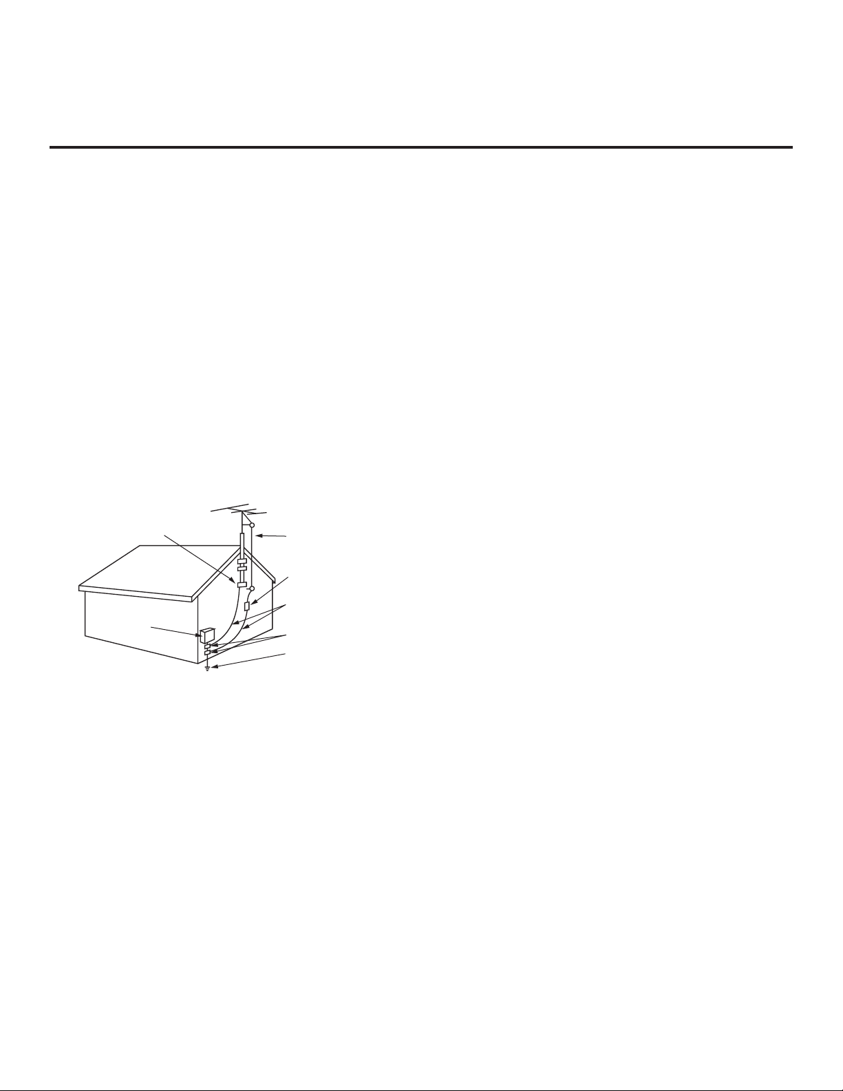
Antenna Grounding According to NEC, ANSI/NFPA 70
Ground Clamp
Electric Service
Equipment
Antenna Lead in Wire
Antenna Discharge Unit
(NEC Section 810-20)
Grounding Conductor
(NEC Section 810-21)
Ground Clamps
Power Service Grounding
Electrode System (NEC
Art 250, Part H)
22. Cleaning
When cleaning, unplug the power cord and wipe gently with
a soft cloth to prevent scratching. Do not spray water or other
liquids directly on the TV as electric shock may occur. Do not
clean with chemicals such as alcohol, thinners or benzene.
23. Transporting Product
Make sure the TV is turned off and unplugged and that all
cables have been removed. It may take two or more people
to carry larger TVs. Do not press against or put stress on the
front panel of the TV.
24. Ventilation
Install the TV where there is proper ventilation. Do not install
in a conned space such as a bookcase. Do not cover the TV
with cloth or other materials (e.g., plastic) while it is plugged
in. Do not install in excessively dusty places.
25. If you smell smoke or other odors coming from the TV or
hear strange sounds, unplug the power cord, and contact an
authorized service center.
26. Keep the product away from direct sunlight.
27. When mounting a TV on the wall, make sure that none of the
electrical cabling bears any of the weight of the TV. Install in
accordance with the manufacturer’s instructions.
28. Do not install this product on a wall if it could be exposed to
oil or oil mist. This may damage the product and cause it to
fall.
29. Do not allow an impact shock or any objects to fall into the
product, and do not drop objects onto the screen.
30. Do not touch the ventilation openings, as they may become
hot while the TV is operating. This does not affect the performance of the product or cause defects in the product.
31. Do not use high voltage electrical equipment near the TV
(e.g., a bug zapper). This may result in product malfunction.
32. Dot Defect
This panel is an advanced product that contains millions of
pixels. In a very few cases, you could see ne dots on the
screen while you are viewing the TV. Those dots are deactivated pixels and do not affect the performance and reliability
of the TV.
33. Generated Sound
“Cracking”: A cracking noise that occurs while the TV is
on or when it is turned off is generated by plastic thermal
contraction due to temperature and humidity. This noise is
common for products where thermal deformation is required.
Electrical circuit humming/panel buzzing: A low level noise is
generated from a high-speed switching circuit, which supplies
a large amount of current to operate a product. It varies
depending on the product. This generated sound does not
affect the performance and reliability of the product.
34. If the TV feels cold to the touch, there may be a small “icker”
when it is turned on. This is normal; there is nothing wrong
with the TV. Some minute dot defects may be visible on the
screen, appearing as tiny red, green, or blue spots. However,
they have no adverse effect on the TV’s performance. Avoid
touching the screen or holding your nger(s) against it for
long periods of time. Doing so may produce some temporary
distortion effects on the screen.
35. Displaying a still image for a prolonged period of time may
cause image burn-in. Avoid displaying a xed image on the
TV screen for an extended length of time.
4
206-4309
Page 5

Table of Contents
Safety Warnings .................................. 2
Important Safety Instructions . . . . . . . . . . . . . . . . . . . . . . 3 – 4
Table of Contents ................................. 5
Commercial Mode Overview ....................6
Setup Checklist ................................. 6
Pass-through Mode.............................. 6
FTG Mode..................................... 7
Application Tuning Mode / Pro:Centric Direct.......... 9
Determining the TV Operating Mode ................
Pro:Centric Operation ........................11 – 15
Interactive Menu Features ........................11
Interactive Menu Navigation .......................11
Pro:Centric Java Application Setup ................ 14
Pro:Centric HTML Application Setup ............... 14
EZ-Manager Wizard ..........................16 – 25
Before You Begin .............................. 16
Initiate Configuration or Exit the EZ-Manager Wizard .. 17
TV Configuration Options . . . . . . . . . . . . . . . . . . . . . . . . 18
Zones and Room Number Assignments............. 18
Configure Pro:Centric Settings .................... 20
USB Configuration ............................. 24
Ez Download Utility ..........................26
Before You Begin .............................. 26
Accessing and Using the Ez Download Utility ........ 26
Installer Menu ...............................30 – 40
Accessing the Installer Menu ..................... 30
Navigating Within the Installer Menu ............... 31
Modifying Installer Menu Settings.................. 31
Exiting the Installer Menu and Activating Settings ..... 31
Detailed Descriptions of Installer Menu Items ........ 34
Custom Master TV Setup..................... 41
Before You Begin .............................. 41
Clonable TV Setup Menu Features ................ 41
Custom Master TV Setup Procedure ............... 42
Cloning Procedures ..........................44
Exporting a Clone File .......................... 44
Importing a Clone File........................... 46
FTG File Manager Utilities Overview ............51 – 56
– 10
– 29
– 43
–
10
50
Creating an FTG Configuration File ................ 51
FTG File Manager Main Screen ................... 53
FTG Channel Map Configuration Utility ............. 54
FTG Channel Map Editor ........................ 55
FTG Installer Menu Configuration Utility............. 56
IP Environment Setup ........................57 – 65
Accessing the IP Environment Menu ............... 57
Network Configuration .......................... 57
Pro:Centric Setup .............................. 61
Media Share Setup ............................. 63
Pre-loaded Applications ......................... 65
References
Remote Jack Pack / TV Connections & Setup.......... 66
Updating TV/PTC Software using a USB Memory
Device......................................67 – 68
Downloading a Splash Screen Image using a USB
Memory Device...............................69 – 70
Downloading Background Images using a USB
Memory Device...............................71 – 72
Power Consumption Settings....................... 73
TV Aux Input Configuration ........................ 74
b-LAN Setup & Overview .......................... 75
FTG Mode via EBL (Local Configuration) ............. 76
Auto Input(s) Sensing Feature ...................77 – 78
RJP Model List & Input Auto-sensing Hierarchy ........ 79
Restoring Factory Defaults on the TV(s) .............. 80
Using the TV’s Zoning Features..................81 – 84
Using Media Share Features ....................85 – 88
LX774H Rear and Side Jack Panels ................. 89
External Stereo Speaker Specifications............... 90
Installer Remote Control Typical Key Functions ........ 91
Troubleshooting ..............................92
General Troubleshooting......................... 92
Commercial Mode Check / FTG Operation
Troubleshooting ................................
Glossary of Terms ............................... 94
Document Revision History / Open Source Software Notice 95
Back Cover..................................... 96
– 93
93
Notes
• Installer Menu content is intended for use primarily by qualied TV electronics technicians.
• Refer to the applicable Owner’s Manual and/or Easy Setup Guide for additional information on TV installation, specications, maintenance,
and safety instructions.
• Design and specications subject to change without prior notice. This document provides examples of typical TV displays. Your displays
may vary from those shown in this document.
206-4309
5
Page 6

Commercial Mode Overview
This document describes how to set up LX774H Pro:Centric ® TVs for Commercial Mode operation.
LG commercial TV functionality is based on “ownership” of the Channel Map; that is, the Channel Map
resides in the TV’s CPU, Protocol Translation Controller (PTC), or embedded b-LAN™ (EBL) module, or
it resides in a Pro:Centric application or an external device from the solution provider.
These TV models support several different operational modes: LG’s Free-To-Guest (FTG) Mode via the
TV CPU, FTG Mode via the TV’s EBL module, Application Tuning Mode (ATM) with Pro:Centric application,
or Pass-through Mode (default). When in Pass-through Mode, these TV models can also be externally
controlled via the Multiple Protocol Interface (MPI).
Setup Checklist
Note: This document provides information specific to Commercial Mode operation. Refer to the Owner’s
Manual and/or Easy Setup Guide for information on TV installation and hardware and cable connections.
Installation
__ Unpack TV and all accessories.
__ Install batteries in the Installer Remote.
__ Install TV on VESA mount or stand.
Note: It may be advisable to make all cable
connections before installing on VESA mount
or stand, as appropriate.
Hardware Connections
__ Install any additional hardware as
appropriate to your institution, LAN, etc.
Cable Connections
__ Make all rear jack panel connections, as
appropriate.
Commercial Mode Setup
__ Complete appropriate procedures as described
in this document for Commercial Mode operation.
Pass-through Mode
This mode allows you to configure individual TVs for Pro:Centric and/or FTG Mode via CPU operation.
This mode also allows external control via the GAME CONTROL/MPI port on the TV rear jack panel.
There are two methods for configuring individual TVs that are currently in Pass-through Mode: either
using the EZ-Manager Wizard or the Custom Master TV Setup procedure as described in this document.
EZ-Manager Wizard
When the TV is in a factory default state, the EZ-Manager Wizard provides automated or manual options
for conguring essential items for Pro:Centric operation and also provides an option for using a USB
memory device to congure the TV. Use the Installer Remote to make selections and complete each step.
See “EZ-Manager Wizard” on pages 16 to 25 for detailed information.
Custom Master TV Setup
The Custom Master TV Setup procedure enables you to create a customized Master TV Setup for
Pass-through Mode or FTG Mode configuration purposes. Use the Installer Remote to congure Installer
Menu items as required for TV operation and set up TV features (Channel, Picture, Sound, etc.). See
“Custom Master TV Setup” on pages 41 to 43 for detailed information.
6
206-4309
Page 7
Commercial Mode Overview (Cont.)
Installer Menu
To create a Master TV Setup, you will need to know how to access
the commercial controller (PTC) Installer Menu and make changes to
the default values as required. If necessary, familiarize yourself with
the Installer Menu and how to make and save changes. See pages 30
to 40 for information on accessing the Installer Menu and for detailed
descriptions of the Installer Menu items.
PTC INSTALLER MENU
xxLX774H
CPU - CTV
000 INSTALLER SEQ 000
TV Setup Menus
On-screen setup menus control the features of the TV. Use the
Installer Remote to access the TV setup menus, and set the TV
features to the desired configuration for the end user.
Cloning
Cloning refers to the process of using a Master TV Setup to congure
a Target TV. The Master TV’s clonable setup menu features should
be congured as part of the Master TV Setup. If there are features
in the Master TV’s setup—channel icons or labels, digital font options,
etc.—that are not set or that are set incorrectly, those features also
will not be set or will be set incorrectly in the Target TVs. See pages
44 to 50 for detailed information on Clone (.tlx) les and cloning
requirements and procedures.
External MPI Control
To control the TV using an external MPI control device, you must
use the TV’s GAME CONTROL/MPI port for communication purposes.
In these TVs, Installer Menu item 118 POWER SAVINGS controls the
power circuitry for both the embedded b-LAN module and the GAME
CONTROL/MPI port; therefore, to ensure that the GAME CONTROL/
MPI port circuitry is powered, thus enabling MPI communication,
Installer Menu item 118 POWER SAVINGS must be set appropriately.
See Installer Menu item descriptions as well as Reference section,
“b-LAN Setup & Overview,” for further information.
Note: These TV models are not equipped with MPI card slots.
FTG Mode
In this mode, an FTG Channel Map enables the decryption of each
Pro:Idiom ® encrypted channel. The FTG Channel Map also provides
logical channel mapping of physical RF channels (digital and analog),
IP streams, and Aux inputs. The method for creating the FTG Channel
Map is ultimately determined by which element of the TV will “own”
the FTG Channel Map—the CPU or the EBL.
For these TV models, there are two FTG Modes—FTG Mode via CPU
and FTG Mode via EBL—which are separate and distinct FTG Modes
of operation, each with its own unique advantages and requirements,
as outlined on the following page.
UPN 000-000-000-000 SW 5331 7F60
PTC V#.##.### CPU V#.##.##.##
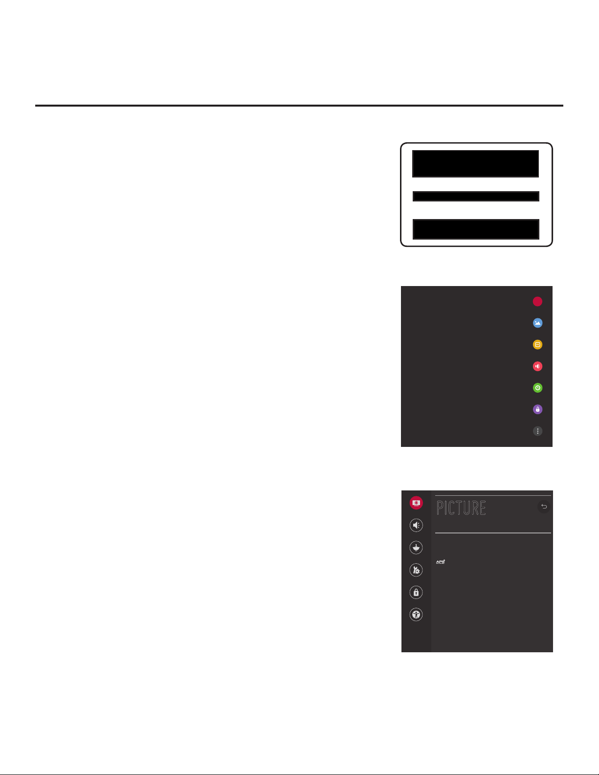
Typical Installer Menu
X
TV Setup Menus (Quick Settings)
Picture
PICTURE
Sound
Channels
General
Safety
Accessibility
Smart Picture Mode
O
Picture Mode Settings
Aspect Ratio
16:9
^
TV Setup Menus (Advanced Settings)
206-4309
7
Page 8

Commercial Mode Overview (Cont.)
When the TV CPU is configured with an FTG Channel Map, the CPU controls and restricts the tuning
operation of the TV, and when the EBL is configured with an FTG Channel Map, the EBL controls and
restricts the tuning operation of the TV. In these models, depending on the types of channels included in
the FTG Channel Map, FTG Mode via CPU also provides the option to select either logical or physical
tuning (see notes at the top of the following page) during configuration. You must determine which element
of the TV will own the FTG Channel Map before you can begin configuration.
FTG Mode via CPU
This mode provides the following features:
• Logical or physical channel tuning of physical RF
channels and Aux inputs.
• Logical channel tuning of IP streams.
• Mapping of RF channels with minor (program) numbers
up to 999.
• FTG Channel Map of up to 600 channels.
• Start Channel set for RF, Aux input, or IP delivered
content.
• Pro:Centric data delivery over RF or IP.
• TV Zoning (including channel restrictions by Zone) and
Wi-Fi Zoning options for location-specic conguration.
LG’s FTG File Manager PC software enables you to
create an FTG Conguration (.tlx) le, which may be used
to congure the CPU for FTG Mode. You can also create a
Clone (.tlx) le from a Master TV Setup that may be used
to congure the CPU for FTG Mode.
Note: TV Zoning and Wi-Fi Zoning features are
supported via “.tlx” le. See Reference section, “Using
the TV’s Zoning Features,” for further information.
In this mode, the CPU is the owner of the FTG Channel
Map and must be congured with an FTG Channel Map
and FTG Installer Menu settings using one of the following
processes:
• Local: Congure an individual LX774H TV via its USB
port using a USB memory device / “.tlx” le. The le
may be either a Clone le (see “Cloning Procedures” on
pages 44 to 50) or an FTG Conguration le (see “FTG
File Manager Utilities Overview” on pages 51 to 56).
• Remote: Congure all LX774H TVs at the site using
a Pro:Centric server head end device (Example:
PCS200S). Refer to the Pro:Centric Server Admin
Client User Guide for further information.
FTG Mode via EBL
This mode provides the following features:
• Logical channel tuning of physical RF channels and
Aux inputs.
• Mapping of RF channels with minor (program) numbers
up to 255.
• FTG Channel Map of up to 141 logical channels.
• Start Channel set for RF or Aux input delivered content.
• Pro:Centric data delivery over RF.
LG’s FTG Device Conguration Application PC software
is required to congure the EBL. In this mode, the EBL
is the owner of the FTG Channel Map and must be
congured with an FTG Channel Map and FTG Installer
Menu settings using one of the following processes:
• Local: Congure an individual LX774H TV’s EBL
via its TV-LINK CFG jack using a direct PC-to-TV
(EBL) connection and the FTG Device Conguration
Application. See Reference section, “FTG Mode via
EBL (Local Conguration),” for information on the
“Write” process for an FTG Channel Map and FTG
Installer Menu settings.
• Remote: Congure all LX774H TV EBLs at the site
using a Free-To-Guest Management Appliance (FMA)
head end device (Example: FMA-LG102). Refer to
the Free-To-Guest (FTG) Device Configuration
Application User Guide and/or the Installation &
Conguration Guide for the FMA device for further
information.
8
206-4309
Page 9

Commercial Mode Overview (Cont.)
Note: Logical channel mapping of physical RF channels eliminates dash tuning; for example, physical
19-3 can be mapped to logical channel 9. It also allows physical RF channels, IP streams, and Aux inputs
to be listed in any order, not only in physical numeric ascending order. Physical channel tuning requires
that you include the dash when direct entering RF channel numbers and Aux inputs (the latter designated
by 130-0 through 137-0).
Note: Physical channel tuning is not available when IP channels are included in the FTG Channel Map.
While the TV is in FTG Mode:
• Users can still access the Installer Menu using an LG Installer Remote; however, all Installer Menu items
will be read-only.
• FTG Mode via CPU conguration changes must be made using a “.tlx” le (typically edited in the FTG
File Manager), while FTG Mode via EBL conguration changes must be made using the FTG Device
Conguration Application. FTG Channel Map Conguration and FTG Installer Menu Conguration utilities
in both PC applications enable you to make changes, respectively, to the FTG Channel Map and FTG
Installer Menu settings as necessary. Based on the initial method used to congure the TV for FTG Mode
operation (via CPU or EBL), all subsequent changes must be transferred to either the TV CPU or the EBL
via a process that is in accordance or compatible with that method (see information on local conguration
in this document or refer to documentation for the head end device/server for information on remote
management).
• If it becomes necessary to restore the TV to Pass-through Mode, there are several options that will enable
you to do so. See Reference section, “Restoring Factory Defaults on the TV(s),” for further information.
Pages 51 to 56 provide overviews of the utilities that comprise the FTG File Manager. Refer to the Free-
To-Guest (FTG) File Manager User Guide for further information on the FTG File Manager. Refer to the
Free-To-Guest (FTG) Device Configuration Application User Guide for information on the FTG Device
Configuration Application.
Remote Management in FTG Mode
When the TV is configured for FTG Mode via CPU, remote management of the FTG Channel Map and FTG
Installer Menu settings is provided by a Pro:Centric server, via a Clone/Configuration (.tlx) file loaded on the
Pro:Centric Admin Client. See the Pro:Centric Server Admin Client User Guide for further information.
When the TV is configured for FTG Mode via EBL, the b-LAN module, which is internal to the TV, allows
hotel/institution head end equipment (for example, an FMA-LG102) with b-LAN technology to provide remote
management of the FTG Channel Map and FTG Installer Menu settings. See Reference section, “b-LAN
Setup & Overview,” for further information.
Application Tuning Mode / Pro:Centric Direct
IIn Application Tuning Mode, the TV’s Channel Map resides in an application, such as LG’s Pro:Centric
Direct HTML application. With Pro:Centric Direct, the Channel Map is created in the Pro:Centric Direct
Admin Client, and the tuning operation of the TV is controlled and restricted based on this Pro:Centric
Direct Channel Map.
Application Tuning Mode with the Pro:Centric Direct HTML application provides the following features:
• Decryption of each Pro:Idiom ® encrypted channel.
• Logical channel tuning of physical RF channels (digital and analog) and IP streams.
• Mapping of RF channels with minor (program) numbers up to 999.
206-4309
9
Page 10
Commercial Mode Overview (Cont.)
• Start Channel set for RF or IP delivered content.
• Pro:Centric data delivery over RF or IP.
• TV Zoning (Installer Menu items only) and Wi-Fi Zoning options for location-specic conguration.
You must use the Pro:Centric Direct Admin Client / Channel Map conguration utility to create the
Pro:Centric Direct Channel Map, dene channel attributes, and set the Start Channel. Refer to the
Pro:Centric Direct Admin Client User Guide for further information.
Note: TV Zoning and Wi-Fi Zoning features are supported via “.tlx” le—typically a Clone (.tlx) le that has
been created from a Master TV Setup. See Reference section, “Using the TV’s Zoning Features,” for further
information.
While the TV is in Application Tuning Mode:
• Users can still access the Installer Menu using an LG Installer Remote; however, all Installer Menu
items will be read-only.
• While it is possible to update a TV’s Installer Menu and/or Setup Menu settings locally using a USB
memory device / Clone (.tlx) le, any Pro:Centric Direct conguration changes are typically made
remotely via the Pro:Centric server / Pro:Centric Direct Admin Client. The Admin Client’s Channel Map
conguration utility enables you to create and edit the Pro:Centric Direct Channel Map, while the TV
Conguration utility (in conjunction with a Clone [.tlx] le loaded on a server carousel) enables you to
make changes to TV Installer Menu and/or Setup Menu settings.
• If it becomes necessary to restore the TV to Pass-through Mode, it is possible to do so. See Reference
section, “Restoring Factory Defaults on the TV(s),” for further information.
Refer to the Pro:Centric Direct Admin Client User Guide for further information on conguration and
management via the Pro:Centric Direct Admin Client.
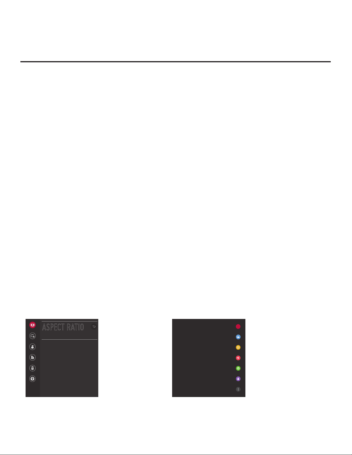
Determining the TV Operating Mode
To determine the operating mode of the TV, press MENU SETTINGS on the Installer Remote. The menu
displayed depends on the operating mode. See examples below.
If the Function Menu appears, the TV is in a mode (FTG, ATM, PPV, etc.) that does not allow the end
user to change the fundamental TV setup. If the TV setup menus (Quick Settings) appear, the TV is in
Pass-through Mode.
X
TV Setup Menus
Shows that the TV is in
Pass-through Mode .
10
Aspect Ratio
ASPECT RATIO
Sound Out
Aspect Ratio
16:9
Audio Mode
General
Safety
Accessibility
^
Function Menu
Indicates the TV is not in
Pass-through Mode . While
the TV is in this mode,
Installer Menu settings can
be accessed as read-only.
206-4309
Page 11

Pro:Centric Operation
These TV models support LG’s Pro:Centric Java application, as well as the Pro:Centric Direct HTML
application. Only one application may be implemented at a time. The following sections provide an overview
of the application features and functionality.
Interactive Menu Features
Both the Pro:Centric Java application and the Pro:Centric Direct HTML application enable guests to
locate and select television entertainment, check the daily weather, view hotel and surrounding amenities,
etc. via custom portal interactive menus. The Pro:Centric Java application provides multiple templates for
portal interactive menus, while the Pro:Centric Direct HTML application, in addition to providing multiple
templates for portal interactive menus, also enables you to custom-create portal and application content.
Pro:Centric application features include:
• Portal and information screens/pages (including a “Welcome” page) that include branding logos.
• An optional customized user interface (custom “skins”).
• Billboards and points-of-interest maps that can be customized to focus on hotel amenities, local
attractions and businesses, restaurants, news, events, etc.
• An optional Weather billboard that includes a local radar map, current conditions, and a four day
forecast.
• An interactive channel guide that provides a channel list with channel icons. An electronic program
guide (EPG) is an optional feature that displays up to three days of programming information viewable
by channel and time.
• Video spooling that enables the hotel to deliver a video le to guest TVs for promotion and information
purposes.
In addition to the those indicated above, the Pro:Centric Direct HTML application also offers the following
features:
• Optional messaging features, including notices, ticker text, and ad banners.
• Additional media support, specically music accompaniment, for portal displays.
• An optional ight information display.
For each Pro:Centric application, an Admin Client web editor/content wizard is provided for customer
conguration of portal content. The Pro:Centric Direct Admin Client features the Pro:Centric Direct
Project Editor, which provides design tools (including templates) that enable customization of all portal
pages. Please contact your LG service representative for further information.
Note: Customized content is typically dened by the service integrator and/or hotel administrators. LG
does not provide hotel-specic content.
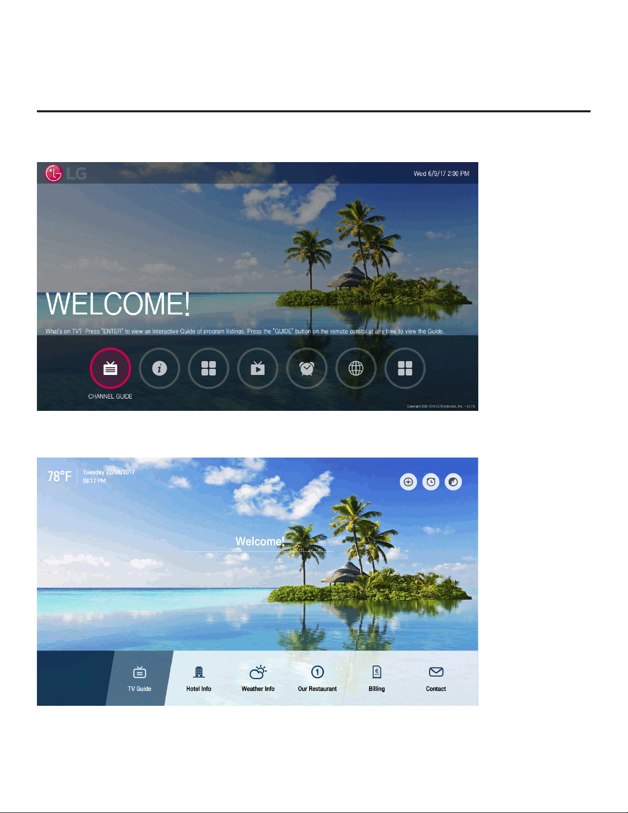
Interactive Menu Navigation
An LG Pro:Centric-capable TV remote control provides access to both interactive menus and regular
TV features. Press PORTAL on the remote to access the interactive menus.
Interactive menu options may vary, depending on Pro:Centric features enabled for the site and/or
customized content. The following examples show typical portal interactive menus.
206-4309
11
Page 12
Pro:Centric Operation (Cont.)
Example: Pro:Centric Java Application Portal
Example: Pro:Centric Direct HTML Application Portal
12
206-4309
Page 13

Pro:Centric Operation (Cont.)
Pro:Centric Java Application Setup
The Pro:Centric Java application operates in conjunction with FTG and/or PPV Modes. This section
provides an overview of the setup required for the Pro:Centric features. Administration and management
options for the Pro:Centric server are described in detail in the Pro:Centric Server Admin Client
User Guide. This document describes only those settings that must be specied on the TVs to enable
Pro:Centric remote management and/or the Pro:Centric Java application.
• Remote management (TV E-Z Installation): The Pro:Centric Admin Client provides remote management
facilities for downloading splash screen image and software/firmware updates as well as facilities for
downloading a Clone/Configuration (.tlx) file for FTG Mode via CPU configuration.
• Pro:Centric Java application: The application comprises the Pro:Centric interactive menus/features
described on page 11. Pro:Centric application settings are managed via the Pro:Centric Admin Client
for the Java application.
The Pro:Centric remote management facilities and application download are based on Installer Menu
item settings that are used to set up the TV’s Pro:Centric features. The Installer Menu / Pro:Centric server
settings can be congured using one of the methods described below.
TV in Factory Default State
When the TV is in a factory default state, the EZ-Manager Wizard provides automated or manual options
for conguring the Pro:Centric server settings.
The EZ-Manager Wizard also provides a USB conguration option that enables you to congure a TV for
FTG Mode via CPU using a Clone/Configuration (.tlx) le stored on a USB memory device. The “.tlx” le
incorporates FTG Installer Menu settings, including Installer Menu items 098 PRO:CENTRIC and 119 DATA
CHANNEL, which are used to set up the TV’s Pro:Centric features.
Refer to “EZ-Manager Wizard” on pages 16 to 25 for further information on the EZ-Manager Wizard options.
Note: If Pro:Centric data delivery will be over IP and there is a Domain Name System (DNS) server at
the site, you can create a “procentric.local” DNS entry for the Pro:Centric server that will enable automated
Pro:Centric IP conguration via the EZ-Manager. If there is no DNS entry for procentric.local, you will need
to manually enter the Pro:Centric server IP address and port number during conguration.
TV in Pass-through Mode
If the EZ-Manager Wizard has been exited and the TV is in Pass-through Mode, either:
• Set Installer Menu items 098 PRO:CENTRIC and 119 DATA CHANNEL to the appropriate values.
See Installer Menu information on pages 30 to 40 for further details. Also, as necessary, refer to
“Custom Master TV Setup” on pages 41 to 43 and/or cloning information on pages 44 to 50.
• Congure the appropriate Pro:Centric server settings in the IP Environment / Pro:Centric Menu. You
must use this option, in particular, if you wish to congure IP settings for the Pro:Centric server. See
“Accessing the IP Environment Menu” on page 57 and “Pro:Centric Setup” on pages 61 to 63 for further
information.
Note: When the TV is in either Pass-through Mode or FTG Mode via CPU, you can also leave Installer
Menu item 119 DATA CHANNEL set to its default value (255) to enable the TV’s Data Channel Auto Search
feature to set the DATA CHANNEL value. See item 119 description on page 10 for additional information.
206-4309
13
Page 14

Pro:Centric Operation (Cont.)
TV in FTG Mode
If the TV is already in FTG Mode (via CPU or EBL), use the appropriate FTG application to update Installer
Menu items #98 Pro:Centric and #119 Data Channel (along with their affiliated fields). Then, transfer the
FTG Installer Menu settings to the TV in accordance with the FTG Mode of configuration. Refer to the FTG
Mode overview on pages 7 to 9 for further information on FTG Mode operation and configuration. Also—for
FTG Mode via CPU only—see note above regarding the option to use the TV’s Data Channel Auto Search
feature to set the Data Channel value.
Pro:Centric Direct HTML Application Setup
The Pro:Centric Direct HTML application operates only in Application Tuning Mode (ATM). This section
provides an overview of the setup required for the Pro:Centric Direct features. Administration and
management options for the Pro:Centric server are described in detail in the Pro:Centric Direct Admin
Client User Guide. This document describes only those settings that must be specied on the TVs to
enable Pro:Centric remote management and/or the Pro:Centric Direct HTML application.
• Remote management (TV E-Z Installation): The Pro:Centric Direct Admin Client provides remote
management facilities for downloading splash screen image and software/firmware updates as well as
facilities for downloading Installer Menu configuration updates via Clone (.tlx) file to the TVs at the site/
institution.
Note: The Pro:Centric Direct Channel Map is created and maintained in the Pro:Centric Direct Admin
Client. Thus, any Clone le that is loaded on the server for remote conguration may only contain
Installer Menu and/or Setup Menu proles.
• Pro:Centric Direct HTML application: The application comprises the Pro:Centric interactive menus/features described on page 11. Pro:Centric Direct application settings are managed via the Pro:Centric
Direct Admin Client.
The Pro:Centric remote management facilities and application download are based on Installer Menu
item settings that are used to set up the TV’s Pro:Centric features. The Installer Menu / Pro:Centric server
settings can be congured using one of the methods described below.
TV in Factory Default State
When the TV is in a factory default state, the EZ-Manager Wizard provides automated or manual options
for conguring the Pro:Centric server settings.
The EZ-Manager Wizard also provides a USB conguration option that enables you to congure the
TV’s Installer Menu settings using a Clone (.tlx) le stored on a USB memory device. Installer Menu items
098 PRO:CENTRIC and 119 DATA CHANNEL are used to set up the TV’s Pro:Centric features.
Refer to “EZ-Manager Wizard” on pages 16 to 25 for further information on the EZ-Manager Wizard options.
Note: If Pro:Centric data delivery will be over IP and there is a Domain Name System (DNS) server at
the site, you can create a “procentric.local” DNS entry for the Pro:Centric server that will enable automated
Pro:Centric IP conguration via the EZ-Manager. If there is no DNS entry for procentric.local, you will
need to manually enter the Pro:Centric server IP address and port number during conguration.
14
206-4309
Page 15

Pro:Centric Operation (Cont.)
TV in Pass-through Mode
If the EZ-Manager Wizard has been exited and the TV is in Pass-through Mode, either:
• Set Installer Menu items 098 PRO:CENTRIC and 119 DATA CHANNEL to the appropriate values.
See Installer Menu information on pages 30 to 40 for further details. Also, as necessary, refer to
“Custom Master TV Setup” on pages 41 to 43 and/or cloning information on pages 44 to 50.
• Congure the appropriate Pro:Centric server settings in the IP Environment / Pro:Centric Menu. You
must use this option, in particular, if you wish to congure IP settings for the Pro:Centric server. See
“Accessing the IP Environment Menu” on page 57 and “Pro:Centric Setup” on pages 61 to 63 for
further information.
Note: When the TV is in either Pass-through Mode or Application Tuning Mode, you can also leave
Installer Menu item 119 DATA CHANNEL set to its default value (255) to enable the TV’s Data Channel
Auto Search feature to set the DATA CHANNEL value. See item 119 description on page 10 for additional
information.
TV in Application Tuning Mode
If the TV is already in Application Tuning Mode, use a Master TV of the same model to create and
export a Clone (.tlx) le with the desired settings for Installer Menu items 098 PRO:CENTRIC and 119
DATA CHANNEL. Then, transfer (import) the Clone le to the Target TV. Refer to the Application Tuning
Mode / Pro:Centric Direct overview on pages 9 to 10 for further information on Pro:Centric Direct operation
and conguration. To transfer the Clone le remotely, use the appropriate utilities in the Pro:Centric Direct
Admin Client to upload the Clone le to the Pro:Centric server and set up its distribution to the Target
TV(s) at the site. See also note above regarding the option to use the TV’s Data Channel Auto Search
feature to set the DATA CHANNEL value.
206-4309
15
Page 16

EZ-Manager Wizard
Note: After it is turned ON, the TV begins an initialization process, and it may take several minutes
for the EZ-Manager Wizard to appear.
The primary purpose of the EZ-Manager Wizard is to guide you through the process (automated or
manual) of configuring the essential Installer Menu items for Pro:Centric operation. The wizard will
appear on the screen each time the TV is turned ON, until one of its configuration methods has
been completed or the wizard is exited. Use the Installer Remote to make selections and complete
each wizard step.
While the EZ-Manager Wizard is intended primarily for Pro:Centric-related conguration, the
wizard also offers Zoning as well as USB conguration options.
• LX774H TVs support the TV Zoning and Wi-Fi Zoning features, both of which enable location-
specic settings (see Reference section, “Using the TV’s Zoning Features,” for further information).
The EZ-Manager Wizard enables you to set the TV Zone # and/or the Wi-Fi Zone # in the TV as
part of the conguration process.
• The EZ-Manager Wizard also enables you to access the TV Manager / USB download options
as part of the conguration process, if desired, to perform USB conguration and/or update
functions.
Caution: Do NOT unplug the TV power cord or remove the antenna cable or, if
applicable, the LAN cable during the conguration process, as doing so will interrupt
the current step and may corrupt the conguration data.
Before You Begin
• If you plan to create a Master TV Setup using the procedure described on pages 36 to 38, be
sure to exit the EZ-Manager Wizard in order to avoid setting modes that may restrict the custom
setup procedure. See also “Initiate Conguration or Exit the EZ-Manager Wizard” on the following
page.
• If it has been completed or exited and therefore does not display, the EZ-Manager Wizard can
be reactivated; however, this requires that you restore the TV to a factory default condition. See
Reference section, “Restoring Factory Defaults on the TV(s),” for further information.
• Each wizard step is allotted a time frame after which the wizard proceeds without user interaction.
If the Pro:Centric server is congured on the system and if no location-specic settings are
required in the TV, for example, TV Zone, Wi-Fi Zone, Label, and/or Room Number settings,
you can simply turn ON the TV, and once initiated, the wizard will proceed through each of the
conguration steps with no further user interaction.
• If any of the conguration steps fails, you will see a “Diagnostics” screen with an indication of the
failure. You will then have the opportunity to reinitiate the conguration process from the previous
screen or exit the EZ-Manager Wizard.
• If you would like to enable the DIAL and/or SoftAP Media Share features or select pre-loaded/
Smart Launcher applications on a TV that will eventually be congured for FTG Mode, you will
need to use the IP Environment Menu to do so before the TV is congured for FTG Mode. Refer
to “IP Environment Setup” on pages 57 to 65 for information on the IP Environment Menu.
See also “Custom Master TV Setup” on pages 41 to 43.
16
206-4309
Page 17

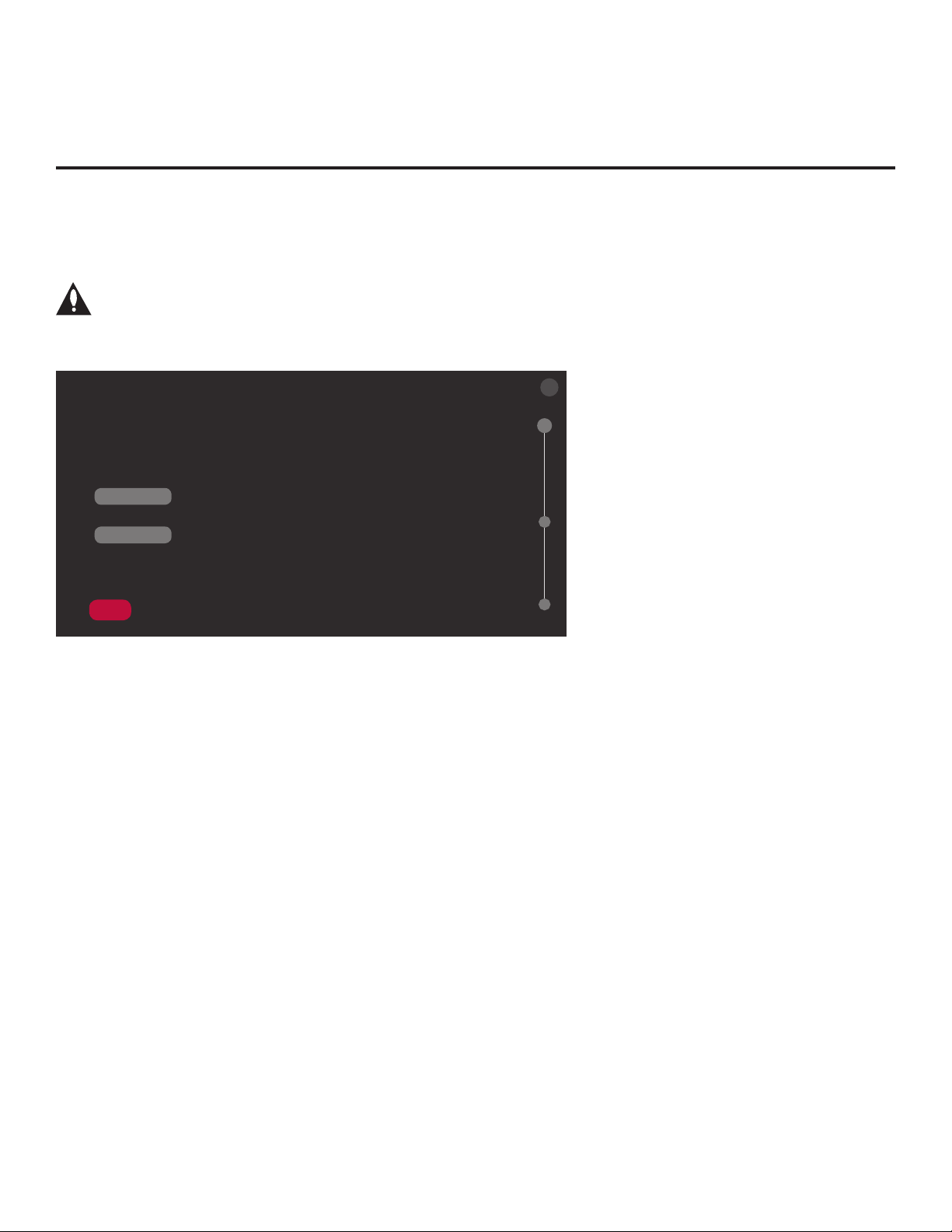
Initiate Conguration or Exit the EZ-Manager Wizard
The Welcome screen provides a brief introduction to the EZ-Manager Wizard.
X
WELCOME TO THE EZ-MANAGER WIZARD
.
Use the EZ-Manager Wizard to configure the TV for Pro:Centric operation or to configure the TV using
a USB memory device.
.
If a Pro:Centric server will not be installed, you may select NO PRO:CENTRIC below to disable the Pro:Centric
feature of this TV and exit the EZ-Manager Wizard.
.
If you simply wish to exit the EZ-Manager Wizard, select
Select NEXT to continue.
This wizard will start automatically in 10 seconds.
NOPRO:CENTRIC
NEXT
X
in the top right corner of the screen.
EZ-Manager Wizard (Cont.)
Note: If there is no user action in this screen within 10 seconds, the wizard will proceed to the
rst conguration step. Once the wizard has proceeded, it is not possible to return to the Welcome
X
screen; however, if you simply wish to exit the wizard, you can do so by selecting the
button from
the subsequent screen(s).
From the Welcome screen, you have the following options:
• To proceed with the EZ-Manager Wizard, use the arrow keys on the Installer Remote to select/
highlight NEXT, and then press OK. Then, continue to the “TV Conguration Options” section on
the following page.
• To exit the wizard, but retain the use of the Pro:Centric remote management feature on this TV
(i.e., Installer Menu item 119 DATA CHANNEL set to 255) in the future, use the arrow keys on
X
the Installer Remote to select/highlight the
button at the top right of the screen, and then press
OK. In the conrmation pop-up window, select EXIT, and then press OK once more on the
Installer Remote.
• If you do not intend to install a Pro:Centric server on this system and you do not wish to use the
wizard’s Zoning or USB conguration options, exit the wizard as follows: Use the arrow keys on
the Installer Remote to select/highlight NO PRO:CENTRIC, and then press OK. This will disable
the Pro:Centric feature of this TV (i.e., Installer Menu item 119 DATA CHANNEL will be set to 0)
and exit the wizard. In the conrmation pop-up window, select EXIT, and then press OK once
more on the Installer Remote.
206-4309
17
Page 18
EZ-Manager Wizard (Cont.)
TV Conguration Options
From the TV Conguration Options screen, you can choose how to proceed with the conguration
of this TV (assuming you do not opt to exit the wizard, which you may also do at any time).
Note: If you intend to use the Zoning feature(s) on the TV for location-specic
conguration purposes, select the “Zones & Room Number” option from this screen
and assign the appropriate TV Zone # and/or the Wi-Fi Zone # in the TV BEFORE you
continue with additional conguration.
X
TV CONFIGURATION OPTIONS
.
To configure the TV for Pro:Centric operation, select NEXT.
.
To set the optional Zoning features, select ZONES & ROOM NUMBER.
ZONES & ROOM NUMBER
.
To configure the TV using a USB memory device, select USB CONFIGURATION.
USB CONFIGURATION
This wizard will continue automatically in 60 seconds.
NEXT
01
Note: If there is no user action in this screen within one minute, the wizard will automatically
continue to the next conguration step.
Use the Up/Down arrow keys on the Installer Remote to navigate between options on this screen.
• To continue with Pro:Centric conguration, select NEXT (default) and press OK on the Installer
Remote. See “Congure Pro:Centric Settings” on pages 20 to 24 for additional information.
• To set the Zoning feature(s) on the TV, select ZONES & ROOM NUMBER. See “Zones and
Room Number Assignments” below for further information.
• To access the TV Manager / USB download options, select USB CONFIGURATION. See “USB
Conguration” on pages 24 to 25 for further information.
Note: If you choose to exit the EZ-Manager Wizard from this point on, you will have the option to
save any settings made by selecting SAVE & EXIT in the exit conrmation pop-up window. Or, you
can exit the wizard without saving any settings by simply selecting EXIT in the conrmation pop-up
window.
Zones and Room Number Assignments
You may complete one or more of the elds in the Zones, Label, and Room Number screen or
leave them at their default settings (TV Zone and Wi-Fi Zone) or blank (Label and Room Number),
as desired. However, if you intend to use either of the Zoning features—TV Zoning and/or Wi-Fi
Zoning—on this TV, you MUST specify the appropriate values in the TV Zone and/or Wi-Fi Zone
elds as described on the following page. See also Reference section, “Using the TV’s Zoning
Features,” for further information.
18
206-4309
Page 19

EZ-Manager Wizard (Cont.)EZ-Manager Wizard (Cont.)
Note: Zoning features are only applicable for TVs that will be congured using a “.tlx” le (local or
remote conguration).
ZONES, LABEL, AND ROOM NUMBER
.
Wi-Fi Zone
<
TV Zone
<
Label
<
Room Number
Room Number
0
0
-----
If creating Wi-Fi Zones for AP settings, select the appropriate Wi-Fi
Zone # (1-99) based on the Wi-Fi Zone in which this TV is installed.
>
.
If creating Zones for Installer Menu settings and/or Channel Mapping,
select the appropriate TV Zone # (0-8) based on the Zone in which
>
this TV is installed. (See Commercial Mode Setup Guide for more
information.)
.
Select a Label and/or input the Room Number, as required.
>
.
When done, select SAVE to continue.
02
BACK
BACK
SAVE
SAVE
1. Complete the appropriate eld(s) as described below. Use the Up/Down arrow keys on the
Installer Remote to navigate between each of the elds.
• Wi-Fi Zone: Enables you to set a Wi-Fi Zone # so that the TV can be congured with a
particular access point’s login data for wireless networking. Login data (i.e., SSID, security type,
and security key) may be provided in a Clone/Conguration (.tlx) le.
To assign a Wi-Fi Zone, navigate to the Wi-Fi Zone eld at the top left of the screen, and use
the Left/Right arrow keys to specify the desired Wi-Fi Zone # (1–99).
• TV Zone: Enables you to set a TV Zone # so that the TV can be congured with Installer Menu
and/or Setup Menu settings intended only for the assigned Zone. The Installer Menu and/or
Setup Menu settings may be provided in a Clone/Conguration (.tlx) le. If the TV is being
congured for FTG Mode, the TV Zone # setting also allows the TV to omit channels that have
been restricted in the FTG Channel Map.
To change the TV Zone from its default value (0), navigate to the TV Zone eld, and use the
Left/Right arrow keys to specify the desired TV Zone # (1–8).
• Label: Allows you to select a North, South, East, or West text label for this TV. In the Label
eld, use the Left/Right arrow keys to select the applicable label.
• Room Number: Allows you to specify the number of the room—up to 16 characters—in
which the TV is located. To enter a room number, navigate to the Room Number eld and
press OK. You can then use the number keys on the Installer Remote to direct enter a room
number, or you can use the arrow keys to select the appropriate alphanumeric character(s)
from the pop-up virtual keyboard at the bottom of the screen. When you are done, select
Enter from the virtual keyboard, and then press OK on the Installer Remote.
Note: The TV name (default: TV’s serial number) will be changed to the room number specied
here. See “Media Share Setup” on pages 63 to 64 for further information on the TV name.
2. When you are ready to continue, use the arrow keys to select SAVE, and then press OK on the
Installer Remote to return to the TV Conguration Options screen. Then, proceed as required;
i.e., select NEXT to congure Pro:Centric settings or select USB CONFIGURATION to use a
USB memory device to complete the conguration.
206-4309
19
Page 20

EZ-Manager Wizard (Cont.)
Congure Pro:Centric Settings
Once you select “NEXT” from the TV Conguration Options screen, the Searching for Pro:Centric
Server screen is displayed.
Note: Select the “BACK” button, where available, to check previous settings, as necessary.
X
SEARCHING FOR PRO:CENTRIC SERVER...
This step automatically searches for the Pro:Centric Server.
If there is no Pro:Centric Server installed, you do not need to continue with this procedure.
In this case, you can either select
PRO:CENTRIC below to enter the Pro:Centric Server settings manually.
Status: Tuning channel 30
TV is now searching the pre-defined channels for the data channel...
X
in the top right corner of the screen to exit or select MANUAL
BACK
MANUALPRO:CENTRIC
03
You have the following options:
• You can allow the EZ-Manager Wizard to proceed with a series of automated steps to congure
the TV for Pro:Centric operation and then to look for the Pro:Centric application and maintenance
(E-Z Installation) les to download. In this case, the wizard uses a search algorithm to determine
the Data Channel and the Pro:Centric Application Mode to set in the TV.
Continue with the “Automated Pro:Centric Conguration” subsection below.
• If you already know the settings (e.g., Data Channel and Pro:Centric Application Mode) that need
to be congured in order for the TV to connect to the Pro:Centric server and/or if the Pro:Centric
server is not yet installed, you may expedite the setup process by entering this data manually.
Continue with the “Manual Pro:Centric Conguration” subsection on page 22.
Automated Pro:Centric Conguration
Note: If the server is not yet congured on the system, use the manual conguration option to
congure the Pro:Centric operation. See also note below.
Note: If Pro:Centric data delivery will be over IP and there is a DNS server at the site, you can
create a DNS entry “procentric.local” for the Pro:Centric server that will enable automated
Pro:Centric IP conguration via the EZ-Manager. If there is no DNS entry for procentric.local, you
must use the manual conguration option to congure the Pro:Centric IP operation.
Once the Pro:Centric data channel is found (a Pro:Centric Server Was Found screen will be
displayed) and the Pro:Centric Application Mode is determined, the wizard will advance to the
Processing the Pro:Centric Conguration screen, which shows the progress of the data
downloads (see example on following page). Note that some steps may require a few minutes.
20
(Continued on next page)
206-4309
Page 21

EZ-Manager Wizard (Cont.)
(Continued from previous page)
If the process is successful, no further user interaction is required, though, in some instances, where
the option (for example, “NEXT”) is available, you may manually move forward to subsequent steps
within the wizard to speed up the process.
PROCESSING THE PRO:CENTRIC CONFIGUR...
Downloading the Pro:Centric application files takes a few minutes.
Please wait...
2%
Retrieving files from data channel 70
Application files In progress...
Maintenance Files Synchronizing...
Warning - Do not remove AC power or the signal cables during these steps.
Note: If, after completing the search, the TV is unable to nd the Pro:Centric data channel (while
the Searching for Pro:Centric Server screen is on display), the wizard will stop and show a
Diagnostics screen that enables you to manually return to the previous screen (to reinitiate the
conguration) or exit the wizard.
When the Pro:Centric Conguration is complete, an EZ-Manager Conguration Complete screen is
displayed (see example below), and after 10 seconds, the wizard exits, and the TV turns OFF.
EZ-MANAGER CONFIGURATION COMPLETE
TV will turn o in 10 second(s)
Installed Components
Pro:Centric Application GEM application downloaded
Maintenance Files LX774H_Config.tlx
REBOOT
Pro:Centric Application GEM application downloaded
Maintenance Files LY970H_Config.tlx
TURNOFF
Installed Components
Note: With the EZ-Manager Conguration Complete screen on display, you can also manually turn
off or reboot the TV. If desired, select TURN OFF or REBOOT, respectively, and then press OK on
the Installer Remote.
206-4309
21
Page 22
EZ-Manager Wizard (Cont.)
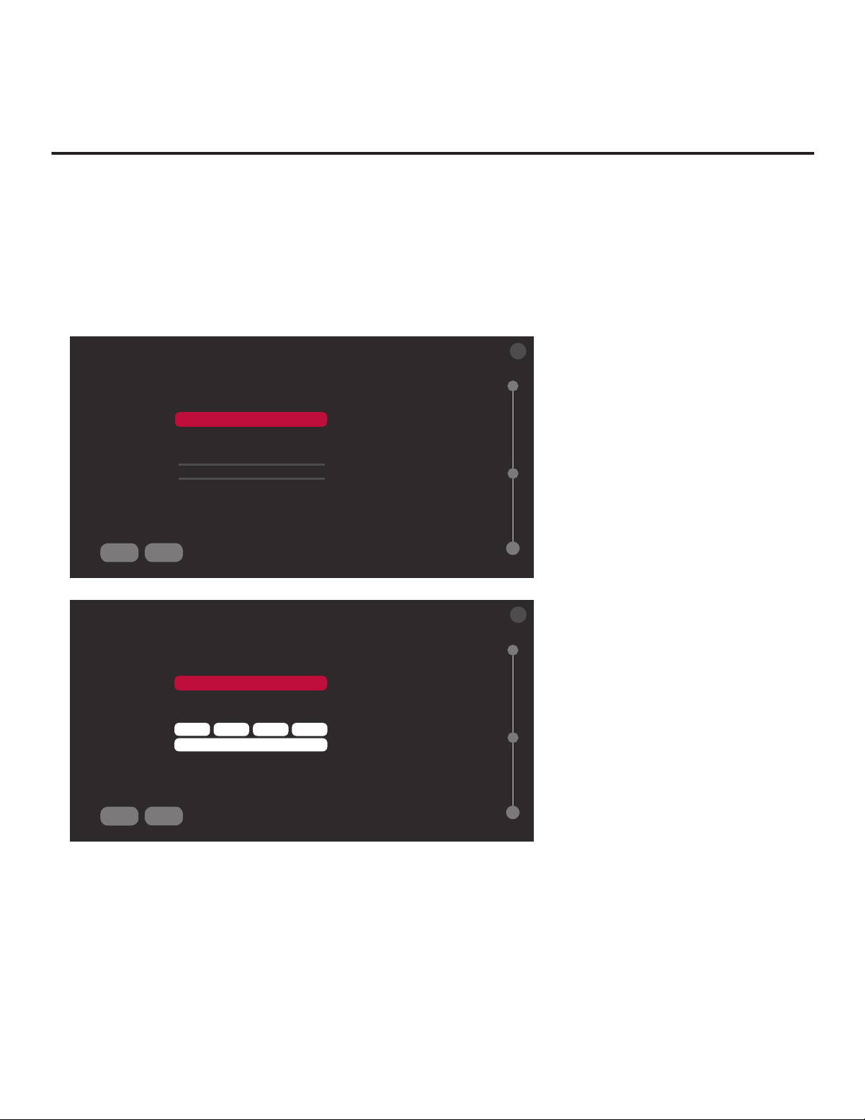
Manual Pro:Centric Conguration
1. With the Searching for Pro:Centric Server screen on display, use the Left/Right arrow keys on
the Installer Remote to select MANUAL PRO:CENTRIC at the bottom of the screen, and then
press OK.
In the Pro:Centric Manual Conguration screen (see examples below), you will be able to
congure the appropriate Pro:Centric settings in the TV. Use the Up/Down arrow keys on the
Installer Remote to navigate between elds.
X
PRO:CENTRIC MANUAL CONFIGURATION
Pro:Centric Mode
Media Type
Data Channel
Signal Strength
Signal Quality
BACK
SEARCH
CONFIGURATION ONLY
<
<
<
data channel not found
>
RF
1
>
>
0%
0%
PRO:CENTRIC MANUAL CONFIGURATION
Pro:Centric Mode
Media Type
Server Address
IP Address
IP Port
BACK
SEARCH
CONFIGURATION ONLY
<
<
<
0
IP server not found
IP
IP Address
0 0 0
0
>
>
>
Pro:Centric Manual Configuration Screen
with RF Media Fields
Note: By default, the Pro:Centric Manual
Conguration screen initially shows RF
conguration elds.
03
X
Pro:Centric Manual Configuration Screen
with IP Media Fields
03
2. In the Pro:Centric Mode eld, use the Left/Right arrow keys to select the appropriate Pro:Centric
Application Mode—FLASH, GEM, HTML, or CONFIGURATION ONLY.
Note: For remote management only, select CONFIGURATION ONLY. The TV will search for
TV E-Z Installation data downloads; however, Pro:Centric application data will not be downloaded,
i.e., Installer Menu item 098 PRO:CENTRIC will be set to 0.
3. Refer to the appropriate subsection below, depending on the Pro:Centric server conguration, to
complete the remaining elds.
22
(Continued on next page)
206-4309
Page 23

EZ-Manager Wizard (Cont.)
(Continued from previous page)
RF Conguration
a) In the Media Type eld, use the Left/Right arrow keys to select RF.
b) In the Data Channel eld, use the Left/Right arrow keys to select the RF channel number
that will be used by the Pro:Centric server as its data channel. The Data Channel value can
be set from 1 to 135. *
IP Conguration
a) In the Media Type eld, use the Left/Right arrow keys to select IP.
Note: When you select “IP” as the Media Type, the default RF Data Channel and Signal
Strength/Quality elds are replaced with Server Address, IP Address, and IP Port elds.
b) The Server Address eld provides the option to specify the domain name of the Pro:Centric
server instead of the server’s IP address. Use the Left/Right arrow keys to select the desired
option—IP Address or Domain Name—for dening the server.
c) Depending on your selection in the previous step, either:
• Enter the Pro:Centric server IP address in the IP Address eld. The IP address must match
the IPv4 multicast address that is set in the Pro:Centric server.
• Enter the Pro:Centric server domain name in the Domain Name eld. Note that in order
for the domain name to be resolved to an IP address, there must be a DNS entry for the
domain name.
For each data entry eld: Use the arrow keys to select the eld and press OK. Then, you
can either use the number keys on the Installer Remote to direct enter data values, or you
can use the arrow keys to select the appropriate number(s)/alphanumeric character(s) from
the pop-up virtual keyboard displayed at the bottom of the screen. When you are done, select
Enter from the virtual keyboard, and then press OK on the Installer Remote.
d) Enter the Pro:Centric server port number in the IP Port eld. The port number must match the
port number that is set in the Pro:Centric server.
4. Once all elds are completed as required, you have two options:
X
• To save the data entered and exit the wizard, use the arrow keys to select the
button at the
top right of the screen, and then press OK. In the subsequent pop-up conrmation window,
select SAVE & EXIT, and then press OK once more. The Pro:Centric application and/or E-Z
Installation data will be downloaded to the TV at a later time. This option is useful, in particular,
if the Pro:Centric server has not yet been congured.
• To initiate a real-time download of Pro:Centric application and/or E-Z Installation data, use the
arrow keys to select SEARCH and press OK to verify the conguration data provided in step 3.
When the data is veried, the “SEARCH” button becomes a “NEXT” button. Select NEXT and
press OK to continue (see also note below).
Note: With RF conguration, Pro:Centric server data must be present on the RF channel
selected as the TV’s Data Channel in order for you to select “NEXT” (you will see a “data
channel found” message below the Signal Quality indicator). With IP conguration, Pro:Centric
server data must be present via the wired LAN cable connection in order for you to select
“NEXT” (you will see a “IP server found” message below the IP Port eld).
* PCS150R and later Pro:Centric servers do not support HRC or IRC cable channel frequencies.
206-4309
(Continued on next page)
23
Page 24

EZ-Manager Wizard (Cont.)
(Continued from previous page)
If you opt to initiate a real-time download in the last step, the EZ-Manager Wizard will proceed with
the Pro:Centric application and/or E-Z Installation data downloads (see Processing the Pro:Centric
Conguration screen example on page 21). When the Pro:Centric conguration is complete, an
EZ-Manager Conguration Complete screen (see example on page 21) is displayed, and after 10
seconds, the wizard exits, and the TV turns OFF.
Note: With the EZ-Manager Conguration Complete screen on display, you can also manually turn
off or reboot the TV. If desired, select TURN OFF or REBOOT, respectively, and then press OK on
the Installer Remote.
USB Conguration
TV Manager / USB download options enable you to download conguration or software les
individually from a USB memory device to the TV. You can also use the Ez Download utility
available from the menu to select multiple types of les to be downloaded at one time using one
process.
Each of the USB download functions requires that you have the appropriate le(s) loaded on a USB
memory device. If you wish to perform a software update or download splash screen/background
image les, the software update/image le(s) must be stored in a folder named “LG_DTV” in the root
directory of the USB memory device. Clone/Conguration (.tlx) les should simply be stored in the
root directory of the USB device.
The procedure below assumes the desired le(s) is/are already loaded onto the USB device. For
further information on the TV Manager / USB download options and le requirements, and/or for
information on creating Clone/Conguration (.tlx) les, refer to the appropriate section(s) in this
document.
Before You Begin
• If you intend to use the Zoning feature(s) on this TV, make sure to assign the appropriate TV
Zone # and/or Wi-Fi Zone # in the EZ-Manager’s Zones, Label, and Room Number screen
BEFORE continuing with USB Conguration. See “TV Conguration Options” on page 18 for
further information.
• Ensure the USB device to be used has been formatted with FAT format.
• When creating les to be downloaded, avoid using special characters (?, &, @, etc.) in lenames.
• Refer to “Ez Download Utility” on pages 26 to 29 for further information on the Ez Download utility.
• Refer to “Custom Master TV Setup” on pages 41 to 43 for information on creating a Clone (.tlx)
file, and/or refer to “Creating an FTG Conguration File” on pages 51 to 52 for information on
creating an FTG Conguration (.tlx) le for FTG Mode via CPU conguration.
• See Reference section, “Downloading a Splash Screen Image using a USB Memory Device,”
for splash screen image guidelines.
• See Reference section, “Downloading Background Images using a USB Memory Device,”
for background image guidelines.
• See Reference section, “Updating TV/PTC Software using a USB Memory Device,” for further
information on software updates.
24
206-4309
Page 25
EZ-Manager Wizard (Cont.)
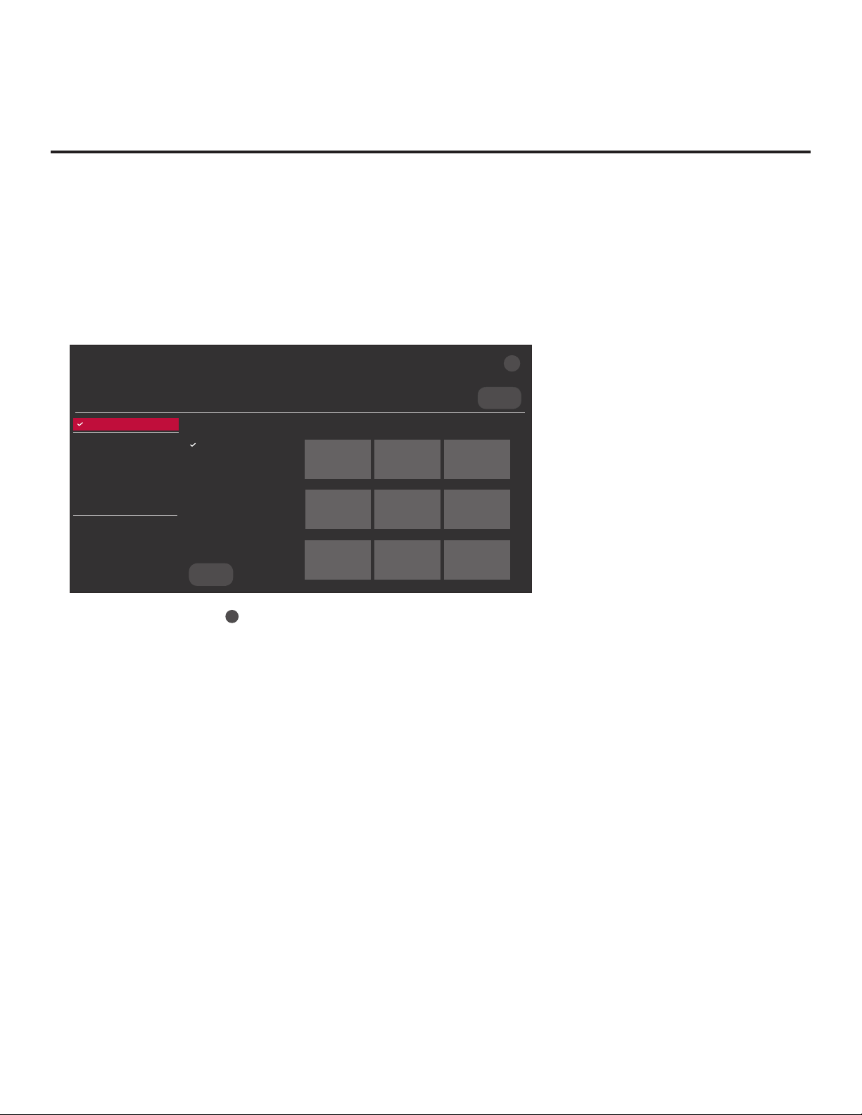
USB Conguration via EZ-Manager Wizard
With either the TV Conguration Options or the Zones, Label, and Room Number screen on display,
proceed as follows to congure the TV using the USB memory device.
1. Insert the USB memory device with the appropriate le(s) into either of the TV’s USB ports.
2. Use the arrow keys on the Installer Remote to select USB CONFIGURATION, and then press
OK.
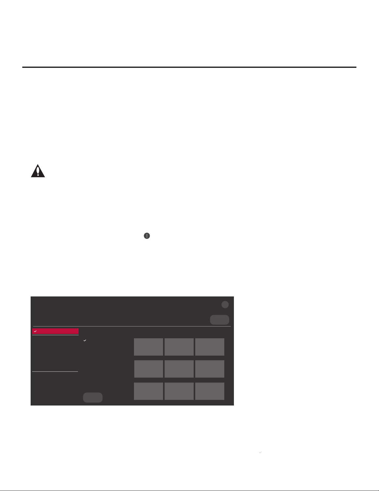
You will be redirected to the TV Manager / USB download options.
X
TV MANAGER
Ez Download
USB 1:
Device Name
Ez Download
Logo Image Download
Insert Background Image(s)
Update TV Software
Update PTC Software
Import Clone File
Diagnostics
Select the file(s) to download, and then select UPDATE below.
Logo Image Download
Splash Image ProC.jpg
Insert Background Image(s)
None
Update TV Software
LX774H_CPU_SW.epk
Update PTC Software
LX774H_PTC_SW.txt
Import Clone File
LX774H_IM.tlx
Image1
.jpg Image2.jpg Image3.jpg
Image4
.jpg Image5.jpg Image6.jpg
USBDEVICE
>
UPDATE
Note: You can select the
Image7
.jpg Image8.jpg Image9.jpg
X
button at the top right corner of the screen and press OK on the
<
Installer Remote at any time to return to the EZ-Manager Wizard.
Note: Ez Download is always selected by default when you initially access the TV Manager.
Also note that Diagnostics is for service use only.
3. If more than one USB memory device is currently connected to the TV, be sure to select the
USB device that contains the le(s) you wish to use. If necessary, use the arrow keys on the
Installer Remote to select/highlight the USB DEVICE button at the top right of the screen and
press OK. Then, use the Up/Down arrow keys to select the appropriate USB device from the
pop-up list of USB devices displayed at the top of the screen.
4. Select the appropriate option from the TV Manager, and initiate the desired download(s).
Update progress will be displayed on the screen. Do NOT remove the USB device while
updates are in progress. When the update process is complete, the TV will reboot. Upon restart,
depending on the type of update(s) completed, either the EZ-Manager TV Configuration Options
screen will be redisplayed (software and/or image updates only) or the TV will tune according
to the Start Channel setting in the Installer Menu (TV configured with Clone/Configuration file).
Note: If the TV Configuration Options screen is redisplayed (software and/or image updates
only), you can either proceed with configuration via the EZ-Manager Wizard or exit the EZManager Wizard, as required.
5. Remove the USB memory device, and verify that the appropriate configuration/update(s) is/are
resident on the TV.
206-4309
25
Page 26

Ez Download Utility
The Ez Download utility, available from the TV Manager, enables you to select multiple les at one
time from the les loaded on a USB memory device. You may use this utility to download any one
or all of the following to a TV:
• One Clone or FTG Conguration (.tlx) le
• One TV CPU software update
• One PTC software update
• One splash screen image
• Up to 12 background images
Before You Begin
• Ensure the USB device has been formatted with FAT format.
• Software update, splash screen image, and background image les must be stored in a folder
named “LG_DTV” in the root directory of the USB memory device. Clone/Conguration (.tlx)
les should simply be stored in the root directory of the USB device.
• If the EZ-Manager Wizard appears on the screen when you turn ON the TV, you can use the
wizard’s “USB Conguration” option to access the Ez Download utility (see “TV Conguration
Options” and/or “USB Conguration” on pages 18 and 24, respectively, as necessary).
• If the TV is currently in Pass-through Mode and you intend to use the Zoning feature(s) on this
TV for location-specic conguration purposes, make sure to assign the appropriate TV Zone #
and/or Wi-Fi Zone # in the TV when directed to do so in the procedure below.
• When creating les to be downloaded, avoid using special characters (?, &, @, etc.) in lenames.
• Refer to “Custom Master TV Setup” on pages 41 to 43 for information on creating a Clone (.tlx)
file, and/or refer to “Creating an FTG Conguration File” on pages 51 to 52 for information on
creating an FTG Conguration (.tlx) le for FTG Mode via CPU conguration.
• See Reference section, “Downloading a Splash Screen Image using a USB Memory Device,”
for splash screen image guidelines.
• See Reference section, “Downloading Background Images using a USB Memory Device,”
for background image guidelines.
• See Reference section, “Updating TV/PTC Software using a USB Memory Device,” for further
information on software updates.
Caution: Do not unplug the TV power cord or remove the USB memory device
during a data download, as doing so may cause the TV to malfunction or harm the
USB device, respectively.
Accessing and Using the Ez Download Utility
1. If it is not ON already, turn ON the TV.
2. The next step depends on whether the EZ-Manager Wizard appears on the screen when you
turn ON the TV:
26
(Continued on next page)
206-4309
Page 27
Ez Download Utility (Cont.)
(Continued from previous page)
• If the wizard is displayed, you can access the Ez Download utility via the wizard, as indicated
above (see “Before You Begin”). However, to continue with this procedure and access the Ez
Download utility from the TV menus, exit the EZ-Manager Wizard. Then, continue with step 3.
• If the wizard is not displayed, go directly to step 3.
3. If the TV is currently in Pass-through Mode, you would like to transfer (import) a “.tlx” le to the
TV via the Ez Download utility, and you intend to use one or both of the TV’s Zoning feature(s),
assign the appropriate TV Zone # and/or Wi-Fi Zone # in the TV at this time. See Reference
section, “Using the TV’s Zoning Features,” for further information.
Note: In order for the proper location-specic TV Zone and/or Wi-Fi Zone prole
data to be applied, the Zone designation(s) must be assigned in the Target TV(s)
BEFORE you continue with the Ez Download utility.
4. Insert the USB memory device with the appropriate le(s) into either of the TV’s USB ports.
5. To access the TV Manager from the TV menus:
• Press MENU SETTINGS on the Installer Remote to display the TV setup menus (TV is in
Pass-through Mode) or the Function Menu (TV is not in Pass-through Mode).
• If the Quick Settings Menu is displayed at the right of the screen (i.e., the TV is in Pass-
through Mode), select the All Settings menu icon and press OK to access the advanced
TV setup menus.
• Use the arrow navigation keys to select/highlight either the General menu icon from the TV
setup menus or the Safety menu icon from the Function Menu. Then, press the number “7”
key a total of seven times.
Note: Ez Download is always selected by default when you initially access the TV Manager.
Also note that Diagnostics is for service use only.
TV MANAGER
Ez Download
USB 1:
Device Name
Ez Download
Logo Image Download
Insert Background Image(s)
Update TV Software
Update PTC Software
Import Clone File
Diagnostics
206-4309
Select the file(s) to download, and then select UPDATE below.
Logo Image Download
Splash Image ProC.jpg
Insert Background Image(s)
None
Update TV Software
LX774H_CPU_SW.epk
Update PTC Software
LX774H_PTC_SW.txt
Import Clone File
LX774H_IM.tlx
UPDATE
Image1
.jpg Image2.jpg Image3.jpg
Image4
.jpg Image5.jpg Image6.jpg
Image7
.jpg Image8.jpg Image9.jpg
USBDEVICE
X
>
<
(Continued on next page)
27
Page 28

Ez Download Utility (Cont.)
(Continued from previous page)
6. If more than one USB memory device is currently connected to the TV, be sure to select the
USB device that contains the le(s) you wish to use. If necessary, use the arrow keys on the
Installer Remote to select/highlight the USB DEVICE button at the top right of the screen and
press OK. Then, use the Up/Down arrow keys to select the appropriate USB device from the
pop-up list of USB devices displayed at the top of the screen.
USB Device
USB 1: Device 1
USB 2: Device 2
7. If it is not currently selected, use the arrow keys to select Ez Download, and then press OK.
As illustrated in the example on the previous page, when Ez Download is selected, a list of
les/le types is displayed on the screen. Remember that Logo (i.e., Splash Screen) Image,
Background Image, TV Software (CPU), and PTC Software les must be stored in the LG_
DTV folder and Clone/Conguration (.tlx) les must be stored in the root directory on the USB
device.
X
Note: Select the
Manager. If you accessed the TV Manager via the EZ-Manager Wizard, you will be returned to
the last screen on display before you selected the “USB Conguration” option. If you accessed
the TV Manager via the TV menus, you will be returned to program viewing.
8. To select a le:
• Use the arrow keys on the Installer Remote to select/highlight the appropriate le type eld,
and then press OK. A list of available les will be displayed to the right of the le type elds.
• Then, use the arrow keys to select the desired le.
Note: With the exception of background image les, the utility will only allow you to select one
of each le type for downloading. For example, if there are two les in the Ez Download “Import
Clone File” list, you can only select one or the other of those two les.
Note: The initial default value for each le type is “None.” After the Ez Download utility is run,
a le is automatically created and stored on the USB device that was used. The le, which
will have a “.dzm” le extension, maintains a history of the le(s) previously used with the Ez
Download utility. The next time(s) you use this USB device with the Ez Download utility, the
le(s) selected for the last download will be pre-selected for the current download, thus
facilitating the process of conguring additional TVs of this model using the same USB device.
Note: The current TV software (CPU) or PTC software version is always displayed above the
listing of available TV software and PTC software les, respectively. Ensure the software version
of the selected le is the correct version before applying the update to this TV.
button in the top right corner of the screen, as necessary, to exit the TV
28
(Continued on next page)
206-4309
Page 29

Ez Download Utility (Cont.)
(Continued from previous page)
9. If a Clone/Conguration (.tlx) le that includes an FTG Channel Map is selected, a Channel
Tuning / Channel Banner Display eld will be displayed at the right of the screen. If the FTG
Channel Map comprises RF channels and Aux inputs only (the latter designated by 130-0
through 137-0), you can choose the format for the channel tuning/banner display. Use the
arrow keys on the Installer Remote to select Logical tuning or Physical tuning. A checkmark
will appear at the left of the selected option. Logical tuning is selected by default.
Note: If an FTG Channel Map includes IP channels, only logical tuning is available. Also, if the
selected “.tlx” le does not include an FTG Channel Map, the message, “No Channel Map in
Clone le,” will be displayed at the right of the screen.
10. When you are ready to continue, use the arrow keys on the Installer Remote to select UPDATE,
and then press OK.
Update progress will be displayed on the screen. Do NOT remove the USB device while
updates are in progress. When the Ez Download process is complete, an overview of the
results will briey be displayed and then, the TV will reboot.
11. Remove the USB memory device, and verify that the appropriate configuration/update(s) is/are
resident on the TV.
Note: If you updated the TV configuration with a Clone/Conguration file, upon restart, the TV
tunes according to the Start Channel setting in the Installer Menu. If a Start Channel is specied,
the TV will tune to that channel, though in the case of FTG Mode via CPU conguration, a channel
banner will only be displayed if the Start Channel is included in the FTG Channel Map (depending
on your selection in step 9, the channel banner will display either the Start Channel’s logical
channel number or physical RF channel number). Otherwise, the TV will either return to the last
channel tuned (TV in Pass-through Mode) or tune to the rst channel in the FTG Channel Map
(TV in FTG Mode via CPU). In the latter case, remember that the channels in the FTG Channel
Map are always arranged in logical order, regardless of your selection in step 9.
206-4309
29
Page 30

Installer Menu
Use the Installer Menu to set up, change, or view operational settings. This section describes how
to access, use, and exit the Installer Menu from the TV itself. However, you should also refer to the
Installer Menu descriptions in this document if you are conguring the TV CPU using an FTG
Conguration (.tlx) le created using LG’s FTG File Manager software or conguring the EBL locally
(.rml) or remotely (via FMA-LG102 / .fma) using the FTG Device Conguration Application software.
Refer to the table on pages 32 and 33 for brief descriptions of Installer Menu items. More
detailed descriptions follow the table listing.
Accessing the Installer Menu
1. Turn ON the TV.
If the EZ-Manager Wizard appears on the screen when you turn ON the TV, exit the wizard.
2. Using an Installer Remote, press MENU SETTINGS repeatedly until the on-screen display of
the TV setup menus (if the TV is in Pass-through Mode) or the Function Menu (if the TV is not
in Pass-through Mode) no longer toggles, and then press the Installer Menu entry sequence
(e.g., 9-8-7-6) + OK to access the Installer Menu.
Note: The default Installer Menu entry sequence is “9876”; however, if Installer Menu item 000
INSTALLER SEQUENCE has been modied, the entry sequence may be one of three additional
options. See Installer Menu detailed descriptions for further information.
The Installer Menu opens with item 000 INSTALLER SEQ 000.
PTC INSTALLER MENU
xxLX774H
CPU - CTV
000 INSTALLER SEQ 000
UPN 000-000-000-000 SW 5331 7F60
PTC V#.##.### CPU V#.##.##.##
PTC Version
CPU Version
Typical Installer Menu
The Installer Menu header will vary
depending on the TV you are setting
up. In the Installer Menu footer, you
can see the current software versions
of the TV, as indicated.
Note: If the password (entry sequence) is not entered or registered correctly, you will see the
message “ENTER PASSWORD 0000” at the top of the screen instead of the Installer Menu
header. Once you re-enter the correct password (e.g., press 9-8-7-6 + OK), the Installer Menu will
display.
Note: If the TV is not in Pass-through Mode, the Installer Menu is accessible as read-only. Also,
the TV Zone # will be indicated in the Installer Menu header under the conguration mode indicator
described below.
30
206-4309
Page 31

Installer Menu (Cont.)
As part of the Installer Menu header (in all modes), two 3-character acronyms are displayed to indicate
the TV’s current conguration mode. The table below lists all possible mode identiers for these TV
models.
Acronym Description
CPU-CTV Pass-through Mode with Channel Lineup in CPU
CPU-FTG FTG Mode via CPU
CPU-P:C Application Tuning Mode via CPU
EBL-FTG FTG Mode via EBL
EBL-LNT SONIFI PPV Mode
MPI-EXT External MPI Control
PTC-CTV Pass-through Mode with Channel Map in PTC
Navigating Within the Installer Menu
Use the Up/Down arrow keys on the Installer Remote to sequence through the available menu items,
or access an item directly by keying in the item number and then pressing MENU SETTINGS. For
example, to access the SLEEP TIMER option, which is item 015, press 0-1-5 + MENU SETTINGS.
Installer Menu items not relevant to these TV models are not present in the Installer Menu; therefore,
some numbers are missing. For example, item 006 will not appear. In addition, items that are
dependent on other Installer Menu item settings will not be initially accessible. For example, item 046
STRT AUX SRCE will not display in the Installer Menu unless item 004 STRT CHANNEL is set to 0.
See Installer Menu detailed descriptions for further information.
Modifying Installer Menu Settings
Refer to the table starting on the next page for an overview of the available Installer Menu items,
including their item numbers, functions, value ranges, and default values.
To change an Installer Menu item value, use the Left/Right arrow keys on the Installer Remote to
select the appropriate value, or direct enter a valid value. To save the new setting, press OK once
on the Installer Remote. If you have additional items to modify, use the Up/Down arrow keys to
navigate to a new Installer Menu item or access an item directly as described in the previous section.
Note that invalid values will not be saved.
Caution: In order for Installer Menu item changes to be saved, you must press OK as
indicated above and then exit the Installer Menu as described below. Never remove
power from the TV while in the Installer Menu. Also, remember that Installer Menu
settings may affect options available from the TV setup menus or the Function Menu.
Exiting the Installer Menu and Activating Settings
After you have saved all desired Installer Menu item changes (i.e., press OK once on the Installer
Remote to save changes), press OK again to exit the Installer Menu. Any changes you make will be
stored in non-volatile memory.
Note: Each time you exit the Installer Menu in Pass-through Mode, all V-Chip (Parental Control)
settings in the TV are reset to their default values; that is, the Lock System, if previously enabled from
the Safety Menu, will now be disabled, and the individual Parental Control settings will be restored
to default values.
206-4309
31
Page 32

Installer Menu (Cont.)
Installer Menu Items 000 through 071
Item Function Value Range Default Value Brief Description of Function
000 INSTALLER SEQ 0 – 3 0 Leave default set to 0.
001 POWER MANAGE 0 – 7 0
002 AC ON 0 – 3 0
003 BAND/AFC 0 – 3 1 Selects Tuning Band: 0=Broadcast, 1=CATV, 2=HRC, 3=IRC
004 STRT CHANNEL 0 – 127, 253, 255 255
005 CHAN LOCK 0 / 1 0 If set to 1, cannot tune from current channel.
007 STRT VOLUME 0 – 63, 255 255
008 MIN VOLUME 0 – 63 0 Sets minimum allowable volume setting.
009 MAX VOLUME 0 – 63 63 Sets maximum allowable volume setting.
010 MUTE DISABLE 0 / 1 0 Set to 1 to disable Mute Function.
011 KEY DEFEAT 0 / 1 0
015 SLEEP TIMER 0 / 1 1 Set to 1 to enable Sleep Timer.
016 EN TIMER 0 / 1 0 Set to 1 to enable On/Off Timers.
017 ALARM 0 / 1 1 Set to 1 to enable Alarm.
020 FEATURE LEVEL 0, 16 – 24 0 Determines an additional IR code scheme to which the TV will respond.
021 V-CHIP 0 / 1 1 Set to 1 to enable V-Chip (Parental Control) functions.
022 MAX BLK HRS 0 – 99 12 Sets number of V-Chip blocking hours.
023 CAPTION LOCK 0 / 1 0 Set to 1 to retain caption setting set before TV turned OFF.
028 CH. OVERIDE 0 / 1 1
029 OLD OCV 0 / 1 0 Set to 1 to remap the PTC’s direct tune channels for Aux inputs from 13x to 9x.
030 ACK MASK 0 / 1 0 If set to 1, enables ACK feature of MPI.
031 POLL RATE 20 – 169 94 Selects poll rate for MPI.
032 TIMING PULSE 186 – 227 207 Sets baud rate for MPI.
035 HDMI1 ENABLE 0 – 2 1
038 YPrPb EN. 0 / 1 1 Set to 1 to enable display panel Component input jacks.
039 REAR AUX EN. 0 / 1 1 Set to 1 to enable display panel AV input jack.
041 SIMPLINK EN 0 / 1 0 Determines the status of the SIMPLINK feature. (See detailed descriptions.)
042 AUTO INPUTS 0 – 255 0
046 STRT AUX SRCE 1, 3, 5 – 7, 255 7 Sets the starting Aux source (if item 004 STRT CHANNEL is set to 0).
047 AUX STATUS 0 / 1 0
049 DIS. AUDIO M. 0 – 9 0
053 DIS. CH-TIME 0 / 1 0 Set to 1 to disable the TV’s native Channel-Time display.
069 EN. CH-T COL. 0 / 1 1 Set to 1 to enable custom color for MPI display characters.
070 FOR. CH-TIME 0 – 7 2 Chooses custom foreground color for MPI display characters.
071 BCK. CH-TIME 0 – 7 2 Chooses custom background color for MPI display characters.
Selects the number of hours of inactivity allowed before the TV automatically
turns itself OFF. Set to 0 to disable Power Management.
Set to 1 to enable TV to turn ON when AC power is applied. Set to 2 or 3 to
enable Instant ON when AC power is applied. (See detailed descriptions.)
Channel tuned when TV is turned ON. (Set to 255 to tune to channel
tuned before TV turned OFF.)
Volume level when TV is turned ON. (Set to 255 to use volume level
before TV turned OFF.)
If set to 1, joystick button menu navigation functions on display panel are
not available.
If set to 0, users can only tune to channels that are included in the PTC
Channel Map. (See detailed descriptions.)
Set to 0 to disable HDMI 1. Set to 1 (DTV Mode) or 2 (PC Mode), as
applicable, to enable HDMI 1.
Determines the Aux inputs for which auto-sensing is enabled. (See detailed
descriptions.)
Controls MPI status channel response for Aux sources. Set to 1 for the Aux
source to be reported as its channel number.
Determines the availability of the Sound Out (Audio) Menu in the TV menus, as
well as the default Audio Mode when TV is turned ON. (See detailed descriptions.)
32
206-4309
Page 33

Installer Menu (Cont.)
Installer Menu Items 073 through 122
Item Function Value Range Default Value Brief Description of Function
073 CH NOT AVBLE 0 / 1 0
075 REVERT CH 0 / 1 0 If set to 1 and loss of MPI communication occurs, TV tunes to Start Channel.
078 UPN MSB 0 – 255 0 User programmable number, most significant byte.
079 UPN MSB-1 0 – 255 0 User programmable number, most significant byte - 1.
080 UPN MSB-2 0 – 255 0 User programmable number, most significant byte - 2.
081 UPN LSB 0 – 255 0 User programmable number, least significant byte.
082 CHKSM ERROR 0 / 1 1 Enforces rigid MPI checksum.
083 HANDSHK TIME 0 – 5 5 Relaxes MPI timing to be compatible with PC-based Windows-controlled systems.
084 PERMANENT BLK 0 / 1 0 Removes block hours setting for Parental Control and makes block permanent.
086 V. MUTE TIME 0 – 50 0 Use to extend the normal video mute time during channel change.
088 EN NOISE MUTE 0 / 1 1 (Analog channels only) If set to 1, audio is muted if no signal is present.
090 KEY LOCK 0 / 1 0 If set to 1, all display panel joystick button functions are locked. IR is still functional.
091 HDMI2 ENABLE 0 – 2 1
092 HDMI3 ENABLE 0 – 2 1
093 RJP AVAILABLE 0, 1, 2, 5, 6 0
094 SAP MENU EN 0 / 1 1 Set to 1 to enable SAP feature in Function Menu.
096 DEF. ASP. RATIO 0 – 4 2 Sets default aspect ratio at power up. See detailed descriptions and item 106.
097 AUDIO OUTPUT 0 – 9
098 PRO:CENTRIC 0 – 3
099 BACK LIGHTING 1 – 200, 255 255 Sets the level of the TV picture back lighting. (See detailed descriptions.)
101 IR FEEDBACK 0 / 2 0 Set to 2 to disable the TV’s MMR feature.
102 ATSC BAND 0 – 4 4 Selects ATSC band.
103 ATSC TUNE MODE 0 / 1 1 Set to 1 (default) for Physical Channel scan. Set to 0 for Virtual Channel scan.
104 START MINOR CH 0 – 255 0 Selects Minor Start Channel. Set to 0 for NTSC.
106 ASP RATIO LOCK 0 / 1 0
107 BANNER SELECT 0 / 1 1 Selects the type of banner to display during channel change.
116 VIDEO MUTE EN 0 / 1 0
117 FACT DEFAULT 0 / 1 0 Set to 1 to restore the factory default settings of all Installer Menu items.
118 POWER SAVINGS 1, 3, 7 3
119 DATA CHANNEL
121 UPDATE TIME HR 0 – 23, 128 128
122 UPDATE TIME MN 0 – 59, 255 0 Sets the minute for Wake For Update. (See detailed descriptions.)
0 – 135, 253,
255
7
0
255
If set to 1 and item 028 CH. OVERIDE is set to 0, a “CHANNEL NOT
AVAILABLE” message is displayed if user attempts to direct tune a channel that
is not included in the channel lineup.
Set to 0 to disable HDMI 2. Set to 1 (DTV Mode) or 2 (PC Mode), as
applicable, to enable HDMI 2.
Set to 0 to disable HDMI 3. Set to 1 (DTV Mode) or 2 (PC Mode), as
applicable, to enable HDMI 3.
Set to 0 to disable. Set to 1, 2, 5, or 6 for HDMI or DVI Mode. (See
detailed descriptions.)
Set as required in accordance with external audio equipment connected to the
TV. See detailed descriptions.
Set to 0 to disable Pro:Centric operation. Set to 1 for Flash Mode. Set to 2 for
GEM (Java Application) Mode. Set to 3 for HTML Mode.
To retain set aspect ratio on power cycle, set to 1. Set to 0 for default ratio on
power cycle.
(Analog channels only) If set to 1, video mutes (blank screen) when no signal
is present.
Determines the powered status of the embedded b-LAN module and the GAME
CONTROL/MPI port. (See detailed descriptions.)
Set to 0 to disable. Set from 1 to 135 to match the RF channel number used by
the Pro:Centric server as its data channel. Set to 255 to use Auto Search to find
the Pro:Centric RF channel. (See detailed descriptions.)
Sets the Wake For Update hour. The value “128” is displayed as “OFF.” Directly
entering 128 turns the Wake For Update feature OFF.
206-4309
33
Page 34

Installer Menu (Cont.)
Detailed Descriptions of Installer Menu Items
000 - INSTALLER SEQUENCE
Species entry sequence to the Installer Menu.
0 = 9876 1 = 4321
2 = 1478 3 = 3698
001 - POWER MANAGE (Power Management)
Energy saving feature. Determines the number of hours, in the
range 1 to 7, of inactivity allowed, either at the TV control panel
or from the remote, before the TV automatically turns itself OFF. If
set to 0, Power Management is disabled.
002 - AC ON (AC Power Switchable)
If set to 1, this allows the TV to turn ON when AC power is
applied. Pressing the POWER button is not necessary. This is
desirable if the TV is plugged into a switched AC outlet (i.e., a
set-top box). Set to 2 or 3 to enable the Instant ON feature (see
additional information below). Set to 0 (default) for standard TV
turn ON/OFF operation.
The Instant ON feature allows the TV to turn ON when AC power
is applied, but with video and audio muted (Muted ON). The TV
retains its ON status while appearing to be OFF. Pressing the
POWER button toggles Off/On the video and audio mutes, so that
the TV appears to turn ON instantly.
• If this item is set to 2, the TV will reboot and, if applicable (i.e.,
item 119 DATA CHANNEL set from 1 to 135 or 253), check for
and download any available updates from the Pro:Centric server
at every turn OFF. This setting is not recommended if the TV will
be congured with a resident application.
• If this item is set to 3, the TV will not reboot to check for and
download updates at turn OFF, with the following exception:
the rst time the TV is turned OFF after this item is set to 3, the
TV will reboot and initiate an update event (Data Channel Auto
Search and/or check for and download of updates—see also
paragraph below). This setting is recommended if the TV will be
congured with a resident application. In this mode, the standard
check for and download of updates is under application control.
Refer to your site-specic documentation for further information
on conguring the TV with a resident application.
When this item is set to 2 or 3, the TV also will reboot and initiate
an update event once every 24 hours. During the update event,
the TV, as applicable, performs a Data Channel Auto Search (item
119 set to 255) and/or checks for and downloads any available
updates from the Pro:Centric server (item 119 set from 1 to 135 or
253). The time at which this event occurs depends on the setting
of item 121 UPDATE TIME HR. See item 119 and 121 descriptions
for further information. Once the update cycle is complete, the TV
completes the reboot and resumes its Muted ON state.
Note: If set to 1, the TV does not respond to ON/OFF commands
from either the remote or the display panel, and the SLEEP TIMER
is also nonfunctional.
003 - BAND/AFC (Band/Automatic Frequency Control)
There are four possible settings for this option:
0 = Broadcast 1 = CATV (default)
2 = HRC 3 = IRC
If some channels were not found by Auto Tuning (Channel
Search), select the appropriate Band setting here, and add the
channels using the Channel Edit option in the Channel Menu.
004 - STRT CHANNEL (Start Channel)
If active, this function allows you to determine the initial Major
Start Channel number when the TV is turned ON. This feature is
useful for an in-house information channel, since the TV would
always select that channel when it is turned ON. If set to 255,
the last channel tuned before the TV was turned OFF will be the
channel tuned when the TV is turned ON again.
0 = Aux 127 = Map to Major CH 4
1 – 125 = Major Ch. # 253 = IP Start Channel
126 = Map to Major CH 3 255 = Last Channel
For a digital Start Channel, always remember to set item 104 to
the Minor Start Channel number. If setting this item to 0 (Aux),
make sure to also set item 046 STRT AUX SRCE to the appropriate
value.
Note: 126 and 127 are mapped only in SONIFI PPV Mode.
Note: The IP Start Channel shown above can only be set in the
FTG File Manager, which is used to congure TV CPUs for FTG
Mode. The same applies for the additional Major Channel number
range of 128 – 135 in Physical tuning and 128 – 999 in Virtual tuning
mode. When the TV is in FTG Mode via CPU, the appropriate
values will be visible in the (read-only) Installer Menu. For an IP
Start Channel, item 004 will show value 253, the IP address, and
the port number. For an RF Start Channel, item 004 will show the
channel’s Major and Minor numbers.
Note: If the TV is being congured for Application Tuning Mode
operation with Pro:Centric Direct, the Start Channel is set in the
Pro:Centric Direct Admin Client, and Installer Menu item 004 is
automatically updated accordingly. When the TV is in Application
Tuning Mode, the appropriate values will be visible in the (read-only)
Installer Menu. For an IP Start Channel, item 004 will show value
253, the IP address, and the port number. For an RF Start Channel,
item 004 will show the channel’s Major and Minor numbers.
005 - CHAN LOCK (Channel Lock)
Channel Lock is ideal if the system must always be on the same
channel. Changing channels with the Channel Up/Down or keypad
numbers is impossible. Channel Lock is inactive if set to 0 (default).
Generally, this feature is used in connection with item 004 STRT
CHANNEL where the Start Channel may, for example, be set to
3 or 4. If the Start Channel is 3, then the TV will remain locked on
channel 3.
34
206-4309
Page 35

Installer Menu (Cont.)
NOTE: For items 007, 008, and 009
For legacy reasons, the scale used is 0 – 63. The PTC software
will translate this to the 0 – 100 scale used by the TV.
To translate a TV volume level to the Installer Menu value, use
the following formula:
Installer Value = TV Value x 63
100
Enter only the whole number (disregard fractions).
007 - STRT VOLUME (Start Volume)
This function allows the Installer to determine the initial volume
level setting when the TV is turned ON. This feature is useful for
an in-house information channel, since the TV will always select
that volume level when it is turned ON. The range of values is 0
to 63, 255. If set to 255, the last volume level before the TV was
turned OFF will be the current volume level when the TV is turned
ON again.
008 - MIN VOLUME (Minimum Volume)
This function determines the minimum volume level allowable
with the Volume (VOL) Up/Down control. In this way, for example,
someone cannot set the volume too low to hear. The value range
is from 0 to 63. The factory default is 0, which provides the full
range of volume control, if item 009 MAX VOLUME is set to 63. It
is recommended to set the same value on every TV.
Note: The minimum volume level cannot have a value setting
higher than the maximum volume level (described below).
016 - EN TIMER (Enable On/Off Timers)
If set to 1, the Timer function is available to the end user and
enabled continuously. Set to 0 to disable On/Off timers.
Note: The TV clock must be set in order for timers to be used.
017 - ALARM
Gives the installer the option of making the Alarm function available
to the end user. If set to 1, the Alarm function is available to the end
user. Set to 0 to disable the Alarm function.
Note: The TV clock must be set before the Alarm function will work.
020 - FEATURE LEVEL
Determines an additional IR code scheme to which the TV will
respond, allowing for the use of unique IR codes based on “bed
number” in a multi-TV single room installation. First determine the
IR mode; then select the bed number.
Values IR Mode Bed #
0 Disabled N/A
16 – 24 Multi-code Remote 1 – 9
Note: For further information, see documentation for the accessory
package that includes the multi-code remote.
021 - V-CHIP (Parental Control)
Set to 1 to activate V-Chip (Parental Control) and have it available
to the end user to lter and control or otherwise restrict programming content that can appear. Set to 0 to turn the V-Chip feature
Off (not available to user); no programming restrictions can be set.
009 - MAX VOLUME (Maximum Volume)
This function determines the maximum volume level allowable
with the Volume (VOL) Up/Down control. In this way, for example,
someone cannot set the volume level high enough to disturb others.
The value range is 0 to 63, with 63 as the default, which gives the
user the full range of volume control, if item 008 MIN VOLUME is
set to 0. It is recommended to set the same value on every TV.
Note: The maximum volume level cannot have a value setting
lower than the minimum volume level (described above).
010 - MUTE DISABLE
Enables or disables sound mute function. If set to 1, sound cannot
be muted. If set to 0, sound can be muted.
011 - KEY DEFEAT
If set to 1, Key Defeat is enabled, which means that end users
cannot access or navigate within the on-screen menu(s) from the
display panel; i.e., joystick button menu navigation functions will not
be available. Set to 0 to disable Key Defeat. Note that all IR features
remain functional regardless of this setting; users can always
access the menus by pressing MENU SETTINGS on the remote.
015 - SLEEP TIMER
If set to 1, the Sleep Timer feature may be used. If set to 0, the
Sleep Timer is not available.
206-4309
022 - MAX BLK HRS (Maximum Block Hours)
Sets hours from 0 to 99 for the maximum V-Chip (Parental Control)
block hours. Default setting is for 12 blocking hours.
Note: This item is not available in the Installer Menu when item 021
V-CHIP is set to 0 or when item 084 PERMANENT BLK is set to 1.
023 - CAPTION LOCK
If set to 0, captions are OFF when the TV is turned ON. Set to 1 to
use the caption setting congured before the TV was turned OFF
when the TV is turned ON.
028 - CH. OVERIDE (Channel Override)
This item either allows or restricts tuning of channels that are NOT
in the PTC Channel Map. If set to 1, end users can tune channels
that are not in the PTC Channel Map by direct keypad entry. If
set to 0, users are restricted to only the channels that are in the
PTC Channel Map. In the case of CPU-CTV Mode, there are no
channels in the PTC Channel Map; therefore, direct keypad entry
is not available. Also, when this item is set to 0, the PTC Channel
Map (PTC-CTV Mode)/CPU channel lineup (CPU-CTV Mode)
is locked, and user access to channel settings in the TV setup
menus is restricted.
Note: This item is not applicable when the TV is in FTG Mode or
Application Tuning Mode.
35
Page 36

Installer Menu (Cont.)
029 - OLD OCV (On Command Video™)
Set to 1 to remap the PTC’s direct tune channels for Aux inputs
from 13x to 9x. This allows 2-digit only tuning systems (i.e.,
legacy OCV) to direct tune Aux inputs. See also Reference sec-
tion, “TV Aux Input Conguration.”
030 - ACK MASK
MPI Communication Parameter. When set to 1, enables ACK
feature of MPI.
031 - POLL RATE
MPI Communication Parameter. Selects poll rate for MPI. Step size
of 16 ms. Changing from default may affect communication via MPI.
032 - TIMING PULSE
MPI Communication Parameter. Sets baud rate for MPI. Step size
of 4.3 uS. Changing from default may affect communication via
MPI.
035 - HDMI1 ENABLE
Set to 1 to enable HDMI 1 input in DTV Mode. Set to 2 to enable
HDMI 1 input in PC Mode. Set to 0 to disable display panel HDMI
1 input.
Note: This setting is ignored if item 093 RJP AVAILABLE is set to 1.
038 - YPrPb EN. (Rear Component Video Enable)
Set to 1 to enable display panel rear Component input jacks. Set
to 0 to disable display panel rear Component input jacks.
039 - REAR AUX EN. (Rear Aux Enable)
Set to 1 to enable display panel rear Aux (AV) input. Set to 0 to
disable display panel rear Aux (AV) input.
041 - SIMPLINK EN
Set to 0 to disable the SIMPLINK feature. Set to 1 to enable
SIMPLINK functionality (does not enable remote control access to
the SIMPLINK Menu).
Note: When both this item and item 042 AUTO INPUTS are
enabled in the Installer Menu, HDMI inputs will be detected by
SIMPLINK, but the Auto Input(s) Sensing Feature will not function.
042 - AUTO INPUTS
Determines the Aux inputs for which auto-sensing is enabled. Set
to 0 to disable auto-sensing for all available inputs. Set to 255 to
enable auto-sensing for all available inputs. For information on
options for individual input settings, see Reference section, “Auto
Input(s) Sensing Feature.”
Note: In order for auto-sensing to be enabled for an input, that
input must also be enabled in the Installer Menu. For example, to
enable auto-sensing for HDMI 1, item 035 HDMI1 ENABLE must
also be set to 1 or 2. Also, see note above regarding TV operation
when both this item and item 041 SIMPLINK EN are enabled.
Note: When this item is enabled in the Installer Menu, item 093
RJP AVAILABLE is automatically set to 0.
046 - STRT AUX SRCE (Start Aux Source)
Sets the starting Aux source. When turned ON, the TV will tune to
starting Aux source if item 004 STRT CHANNEL is set to 0.
1 = AV 3 = HDMI 1 5 = HDMI 2
6 = Component 7 = HDMI 3 255 = Last Aux
Note: In order for an Aux input to be selected as the starting Aux
source, the input also must be enabled in the Installer Menu.
Note: This item is not available in the Installer Menu unless item
004 STRT CHANNEL is set to 0.
047 - AUX STATUS
Controls MPI status channel response for Aux sources. Set to 1
for the Aux source to be reported as its channel number. Set to 0
for the Aux source to be reported as channel 0. See Reference
section, “TV Aux Input Conguration,” for Direct Access channel
numbers.
049 - DIS. AUDIO M. (Disable Audio Menu)
Determines the availability of the Sound Out (Audio) Menu in the
TV menus. Also determines the default Audio Mode when TV is
turned ON. See the table below and set as required.
Value
0 (default) Enabled TV Speaker
1 Disabled TV Speaker
2 Enabled
3 Disabled
4 Enabled
5 Disabled
6 Enabled LG Sound Sync (Wireless/BT)
7 Disabled LG Sound Sync (Wireless/BT)
8 Enabled TV Speaker + Audio Out (Optical)
9 Disabled TV Speaker + Audio Out (Optical)
Sound Out
Menu Status
Default Audio Mode at TV
Turn ON
External Speaker (Optical/HDMI ARC)
External Speaker (Optical/HDMI ARC)
LG Sound Sync (Optical)
LG Sound Sync (Optical)
Note: If a SIMPLINK-enabled device is connected to the TV
and item 041 SIMPLINK EN is set to 1 (enabled), the SIMPLINK
device Audio Mode will have priority over the setting of this item
when the TV is turned ON.
Note: When this item is set to 6 or 7, the Bluetooth Sound Sync
Media Share feature is not available. If Bluetooth Sound Sync is
currently enabled in the IP Environment / Media Share Menu, it
will be disabled.
053 - DIS. CH-TIME (Disable Channel-Time Display)
Set to 1 to disable the TV’s native Channel-Time display when a
custom channel label/channel information will be provided by the
MPI command. Set to 0 to enable the TV’s native Channel-Time
display.
36
206-4309
Page 37

Installer Menu (Cont.)
069 - EN. CH-T COL. (Enable Display Characters Custom Color)
Set to 1 to enable custom color for MPI display characters. Set to
0 to disable custom color for MPI display characters.
070 - FOR. CH-TIME (Display Characters Foreground Color)
Set the foreground color for MPI display characters according to
the following color chart:
0 = Black 2 = Green 4 = Red 6 = Yellow
1 = Blue 3 = Cyan 5 = Violet 7 = White
If the foreground and background colors for the display characters
are the same, the background will be transparent.
Note: This item and item 071 BCK. CH-TIME also apply to the
“Channel Not Available” message if item 073 CH NOT AVBLE is
set to 1 (enabled).
Note: Items 070 FOR. CH-TIME and 071 BCK. CH-TIME are only
available in the Installer Menu when item 069 EN. CH-T COL. is
set to 1.
071 - BCK. CH-TIME (Display Characters Background Color)
See description for item 070 FOR. CH-TIME above. The color
chart is the same for both items.
073 - CH NOT AVBLE (Channel Not Available)
If set to 1 and item 028 CH. OVERIDE is set to 0, a “CHANNEL
NOT AVAILABLE” message is displayed when a user attempts to
direct tune a channel that is not included in the channel lineup.
Note: This item is not available in the Installer Menu when item
028 CH. OVERIDE is set to 1.
Note: This item is only applicable when the TV is in PTC-CTV
Mode.
075 - REVERT CH (Revert to Start Channel)
If set to 1 and loss of MPI communication occurs, TV automatically
tunes to the specied Start Channel.
Note: This item is not available in the Installer Menu when item
004 STRT CHANNEL is set to 255.
078 - UPN MSB (UPN Most Signicant Byte)
User programmable number, most signicant byte readable by
MPI command. Note: Not linked to serial number.
081 - UPN LSB (UPN Least Signicant Byte)
User programmable number, least signicant byte readable by
MPI command. Note: Not linked to serial number.
082 - CHKSM ERROR (Checksum Error)
Enforces rigid MPI checksum validation. Set to 1 for validation.
Set to 0 to disable (does not check checksum on MPI async port).
SPI is always checked.
083 - HANDSHK TIME (Handshake Time)
Adds an additional delay to the handshake time which is 64 msec,
thus relaxing MPI timing requirements to be compatible with PCbased Windows controlled systems. Range is 0 - 5.
(Timeout = 25.5MS + [25.5 MS* Handshake time].)
084 - PERMANENT BLK (Permanent Block)
Allows Lock (Parental Control) blocking schemes to be permanent
by disabling the blocking hours function. Set to 1 to install Parental
Control restrictions permanently. Set to 0 for user-specied hours
control of blocking schemes.
Note: This item is not available in the Installer Menu when item
021 V-CHIP is set to 0.
086 - V. MUTE TIME (Video Mute Time)
Use to extend the normal video mute time during channel change.
For example, you may wish to extend the normal video mute time
to prevent the display of encrypted video (i.e., from a Pro:Idiom
encrypted channel) that has not yet been decrypted. When set to
0, the normal video mute time is not extended. Set from 1 to 50 to
increase the normal video mute time in 100 ms step increments up
to a maximum of 5 seconds (e.g., the value of 25 represents 2.5
seconds, or 25 x 100 ms = 2.5 seconds).
088 - EN NOISE MUTE (Enable Noise Mute)
Applicable for analog channels only. If set to 1, audio mutes if no
signal is present.
090 - KEY LOCK
If set to 1, Key Lock is enabled, which means that all display panel
joystick button functions will be locked, i.e., non-functional. Set to
0 to disable Key Lock. Note that all IR features remain functional
regardless of this setting.
079 - UPN MSB-1 (UPN Most Signicant Byte-1)
User programmable number, most signicant byte-1 readable by
MPI command. Note: Not linked to serial number.
080 - UPN MSB-2 (UPN Most Signicant Byte-2)
User programmable number, most signicant byte-2 readable by
MPI command. Note: Not linked to serial number.
206-4309
091 - HDMI2 ENABLE
Set to 1 to enable HDMI 2 input in DTV Mode. Set to 2 to enable
HDMI 2 input in PC Mode. Set to 0 to disable display panel HDMI
2 input.
092 - HDMI3 ENABLE
Set to 1 to enable HDMI 3 input in DTV Mode. Set to 2 to enable
HDMI 3 input in PC Mode. Set to 0 to disable display panel HDMI
3 input.
37
Page 38

Installer Menu (Cont.)
093 - RJP AVAILABLE (Remote Jack Pack Available)
• 0 = Remote jack pack is not available or disabled.
• 1 = Legacy Model RJPs: HDMI Mode
Enables RJP feature for use with full cable bundle models. In
this mode, when an HDMI source is connected to the RJP, both
digital video and audio are expected via the HDMI cable. If no
digital audio is present, no audio will be heard.
• 2 = Legacy Model RJPs: DVI Mode
Enables RJP feature for use with full cable bundle models. In
this mode, when an HDMI/DVI source is connected to the RJP,
only digital video is expected via the HDMI cable. Analog audio
is provided via a separate cable, from the source, connected to
an RJP AUDIO IN. If no analog audio cable is connected, tuner
audio will be heard.5 = Scaler Model RJPs: HDMI Mode
Enables RJP feature for use with reduced cable bundle models.
In this mode, when an HDMI source is connected to the RJP,
both digital video and audio are expected via the HDMI cable. If
no digital audio is present, no audio will be heard.
• 6 = Scaler Model RJPs: DVI Mode
Enables RJP feature for use with reduced cable bundle models.
In this mode, when an HDMI/DVI source is connected to the
RJP, only digital video is expected via the HDMI cable. Analog
audio is provided via separate cable, from the source, connected
to an RJP AUDIO IN. If no analog audio cable is connected,
tuner audio will be heard.
Note: See also Reference section, “RJP Model List & Input Autosensing Hierarchy.” Settings 1, 2, 5, and 6 allow the lodge staff to
customize each TV’s RJP setup based on customer requirements.
Note: When this item is enabled in the Installer Menu, item 042
AUTO INPUTS is automatically set to 0.
094 - SAP MENU EN (2nd Audio Program)
Set to 1 to enable the SAP feature in the Function Menu, when
the Function Menu is available (i.e., TV is not in Pass-through
Mode). Set to 0 to disable the SAP feature in the Function Menu,
when the Function Menu is available.
096 - DEF. ASP. RATIO (Default Aspect Ratio)
Selects default aspect ratio at power up:
0 = Set By Program 1 = 4:3
2 = 16:9 (default) 3 = Just Scan
4 = Zoom
Note: This item is not available in the Installer Menu unless item
106 ASP RATIO LOCK is set to 0.
097 - AUDIO OUTPUT
Determines availability and signal type/level (xed speaker,
variable speaker, or xed line level [amplier]) of the audio output to
be used by external audio equipment connected to the SPEAKER
OUT / LINE OUT jack on the TV. Set to 0 to disable audio output.
Otherwise, see the table below and set as required in accordance
with audio equipment. See also Reference section, “External
Stereo Speaker Specifications.”
Value Status
Speaker Output 1 Fixed 0.01 Watts
2 Fixed 0.03 Watts
3 Fixed 0.05 Watts
4 Fixed 0.10 Watts
5 Fixed 0.20 Watts
6 Fixed 0.50 Watts
7 Fixed 1.00 Watt (default)
8 Control with volume
Line Output 9 Fixed line level (typically 400 mVrms ±
100 mVrms @10KΩ) output
098 - PRO:CENTRIC
Selects the Pro:Centric Application Mode. Set to 0 (default) to
disable the Pro:Centric application. Set to 1 for Flash Mode. Set
to 2 for GEM (Java Application) Mode. Set to 3 for HTML Mode.
The TV must be turned OFF for a few seconds to initiate the
Pro:Centric application download. When the TV is turned back ON,
it may take several minutes to load the Pro:Centric application after
the initial download.
Note: This item is not available in the Installer Menu when item
119 DATA CHANNEL is set to 0.
099 - BACK LIGHTING
Sets the TV screen brightness at power up. Default setting is 255.
• 1 - 100 Static Back Lighting
(1 = Dimmest picture, 100 = Brightest picture)
• 101 - 200 Dynamic Back Lighting
(101 = Dimmest picture, 200 = Brightest picture)
If set between 101 and 200, the TV automatically controls back
lighting depending upon the picture level of the current program. If
set to 255, back lighting is controlled via the Picture settings in the
TV setup menus.
101 - IR FEEDBACK
If set to 0 (default), the TV’s MMR (Magic Motion Remote) feature
is enabled, and a compatible LG MMR (not supplied) may be used
with the TV. If set to 2, the MMR feature is disabled.
102 - ATSC BAND
Sets up TV to receive different types of incoming signals:
0 = Broadcast 1 = CATV
2 = HRC 3 = IRC
4 = Same as NTSC
38
206-4309
Page 39

Installer Menu (Cont.)
103 - ATSC TUNE MODE
Sets ATSC tuning mode. Default set to 1 for Physical Channel
scan. Set to 0 for Virtual Channel scan.
104 - START MINOR CHANNEL
Sets Minor Start Channel number at power up. 0 = NTSC. If not
0, number selected is the digital channel’s Minor Start Channel
number.
Note: This item is not available in the Installer Menu when item
004 STRT CHANNEL is set to 0 or 255.
106 - ASP RATIO LOCK (Aspect Ratio Lock)
Set to 1 to retain previous aspect ratio with power off. Set to 0 to
retain default aspect ratio with power off. See item 096 DEF. ASP.
RATIO above.
107 - BANNER SELECT
Selects the type of banner to display during channel change.
Set to 1 for channel label display, plus channel information (full
banner). Set to 0 for channel label display only (small banner).
116 - VIDEO MUTE EN (Video Mute Enable)
Applicable for analog channels only. If set to 1, video mutes
(blank screen) when no signal is present.
117 - FACT DEFAULT (Factory Default)
Set to 1 and press OK to restore the factory default settings of all
Installer Menu items. Once complete, the value returns to 0.
Caution: If set to 1, this clears all Installer Menu custom
settings and restores the factory default settings. It also
clears the channel lineup, including any assigned
channel icons and custom text labels.
Note: See also Reference section, “Restoring Factory Defaults on
the TV(s),” for further information.
118 - POWER SAVINGS
Default set to 3—the power circuitry for both the embedded b-LAN
module and the GAME CONTROL/MPI port is only powered when
the TV is turned ON. When the TV is turned OFF, the embedded
b-LAN and the GAME CONTROL/MPI port are not powered.
Note that the TV must be turned ON in order to communicate with
the embedded b-LAN module for conguration and control when
POWER SAVINGS is set to 3. If POWER SAVINGS is set to 1,
the b-LAN module is always powered.
Similarly, if MPI communication is required for external MPI
control, POWER SAVINGS should be set to 1 so that the GAME
CONTROL/MPI port circuitry is always powered.
Note: See Reference section, “b-LAN Setup & Overview,” for
further information.
Caution: POWER SAVINGS should NEVER be set to 7.
This setting is intended for factory use only.
119 - DATA CHANNEL
Set to 0 to disable. Set from 1 to 135 to match the RF channel
number that will be used by the Pro:Centric server as its data
channel. If left at the default value (255), the TV’s Data Channel
Auto Search feature will be enabled (see additional information
below). *
Data Channel Auto Search feature: When this item is set to 255
(default), once every 24 hours, the TV will initiate a search of 10
predened channels (10, 20, 30, ... 100) and then, if necessary,
perform a complete search of the RF channels (1 to 135) in an
attempt to nd the RF channel used by the Pro:Centric server as
its data channel. If the Pro:Centric RF channel is found, the DATA
CHANNEL value will be changed from 255 to match the server’s
RF channel number. The time at which the Auto Search occurs
depends on the setting of item 121 UPDATE TIME HR. See item
121 description for further information.
Note: Pro:Centric updates are downloaded from the Pro:Centric
server to the TV when the TV is turned OFF. While Pro:Centric
updates are in progress, it is not possible to turn ON the TV.
Note: The Data Channel is automatically set to “253” if Media
Type is set to “IP” either in the EZ-Manager Wizard or in the IP
Environment / Pro:Centric Menu on the TV (see “EZ-Manager
Wizard” on pages 16 to 25 or “Pro:Centric Setup” on pages 61 to
63, respectively) or if Installer Menu item #119 Data Channel is
set to “IP Address” in the FTG File Manager, which is used to
congure TV CPUs for FTG Mode operation. It is not possible to
change the value to “253” directly in the Installer Menu.
121 - UPDATE TIME HR
Based on the settings of this item and item 122 UPDATE TIME MN,
the Wake For Update feature wakes the TV once daily to check for
and, if applicable, download updates from the Pro:Centric server.
Set the Wake For Update hour from 0 to 23. This item uses the
24-hour clock format. The value “128” (default) is displayed as
“OFF.” Directly entering 128 resets the default value (OFF) for this
item, though note that this setting does not mean the TV will not
initiate update events—see additional information below.
Under standard TV OFF/ON operating conditions (i.e., item 002 AC
ON is set to 0), a Wake For Update event occurs when the TV is
OFF and causes the TV’s CPU to temporarily turn ON, perform the
update cycle, and then turn back OFF, all while the TV appears to
be OFF. If item 002 AC ON is set to 2 or 3 for Instant ON, then the
TV’s CPU is always ON and Wake For Update occurs when the TV
is in its Muted ON state (i.e., the TV only appears to be OFF). The
Wake For Update event causes the TV’s CPU to reboot in order
to perform the update cycle and then return to its Muted ON state.
See also description for item 002.
* PCS150R and later Pro:Centric servers do not support HRC or IRC cable channel frequencies.
206-4309
39
Page 40

Installer Menu (Cont.)
Random Distribution of Update Time: If this item is set to 128
(OFF), the time at which a Data Channel Auto Search (item 119
set to 255) and/or an Instant ON update (item 002 set to 2 or 3)
occurs is determined as follows: Each TV initiates the search and/
or checks for updates during the 2 AM hour (if the TV clock is set)
or after two hours of elapsed time from when AC power was
applied (if the TV clock is not set). Also, in this case, a xed
update time minute from 0 to 59 that has been assigned to each
TV is used. (The intention of this feature is to prevent all of the
installed TVs from performing updates at the same time; however,
note that in installations that have a large quantity of TVs with this
feature, there will be some TVs that have the same update minute
assignments.) The update time for the TV is displayed at the right
of this item in the Installer Menu, for example:
121 UPDATE TIME HR OFF 02:34
If the TV display is ON when a Wake For Update event is to occur,
the update will take place the next time the TV is turned OFF.
Note: This item is not available in the Installer Menu when item
119 DATA CHANNEL is set to 0, except when item 002 AC ON is
set to 2 or 3 for Instant ON.
Note: The TV clock must be set in order for a Wake For Update
event to occur at the precise time of day in accordance with item
121 and item 122 settings.
122 - UPDATE TIME MN
Set the Wake For Update minute from 0 to 59. If item 121 is NOT
set to 128 and you wish to invoke the “random” minute assignment
on the TV, set this item to 255. See also description for item 121
UPDATE TIME HR above.
Note: This item is not available in the Installer Menu unless item
121 UPDATE TIME HR is set from 0 to 23.
Note: The TV clock must be set in order for a Wake For Update
event to occur at the precise time of day in accordance with item
121 and item 122 settings.
40
206-4309
Page 41

Custom Master TV Setup
This section describes how to create a customized Master TV Setup for cloning purposes when
the TV is in Pass-through Mode. All cloning (export and import) processes on the TV are performed
via USB memory device / “.tlx” le. The Master TV Setup may be exported to a Clone (.tlx) file,
which can then be used (i.e., imported) to configure either TVs that are to remain in Pass-through
Mode or TVs that are to be configured for FTG Mode.
Cloning requirements and procedures are described in detail on pages 44 to 50.
Note: You can also use the FTG File Manager to create an FTG Conguration (.tlx) le for
FTG Mode via CPU conguration/cloning purposes, if desired (see pages 51 to 52). However,
it is not possible to customize TV setup menu settings in the FTG File Manager. If you wish to
include customized TV setup menu settings in the TV conguration, in addition to the channel
lineup and Installer Menu settings, perform the Master TV Setup procedure to create a Clone
(.tlx) conguration le.
Before You Begin
• It is recommended that you disconnect all Aux inputs if you intend to run Auto Tuning (Channel
Search). Under certain conditions, Auto Tuning is disabled if there is an Aux input active.
• A Clone (.tlx) le comprises Installer Menu settings, IP Environment Menu settings (with the
exception of unique TV attributes and settings), and all TV sources’ (analog, digital, AV, HDMI,
etc.) clonable setup menu settings. See also “Clonable TV Setup Menu Features” list below.
• If the “.tlx” le (either a Clone or FTG Conguration le) to be imported on the Target TV(s)
contains an FTG Channel Map, the Target TV(s) will be congured for FTG Mode via CPU,
though as part of the import process, depending on the types of channels included in the Channel
Map, you may have the option to select either logical or physical channel tuning. If you would like
the Target TV(s) to remain in Pass-through Mode, the “.tlx” le should not include an FTG Channel
Map.
Clonable TV Setup Menu Features
Picture
Smart Picture Mode
Picture Mode Settings
Sound
Smart Sound Mode
Sound Mode Settings
Volume Mode
AV Sync Adjustment
Channels
Channel Tuning
Channel Manager
Channel Label
General
Language
Time & Date
− Clock Mode (Auto/Manual)
− Time Zone
Timers (No Signal Power Off)
Standby Light
Note: Some menu options vary between analog and digital channels and Aux inputs.
Note: The Quick Settings Menu is initially displayed when you press MENU SETTINGS on the
Installer Remote. Select the All Settings menu icon to access the advanced TV setup menus.
Several advanced settings are duplicated in the Quick Settings Menu.
206-4309
Accessibility
Pointer Options
Menu Transparency
Closed Caption
Audio Guidance
TV Power Sound
41
Page 42

Custom Master TV Setup (Cont.)
Custom Master TV Setup Procedure
1. Turn ON the TV.
The next step depends on whether the EZ-Manager Wizard appears
on the screen when you turn ON the TV:
• If the wizard is displayed, the TV is in the required factory default state.
Exit the wizard, and then continue with step 2.
• If the wizard is not displayed, restore the TV to a factory default
condition before continuing with this procedure. See Reference
section, “Restoring Factory Defaults on the TV(s),” as necessary,
for further information.
2. Set Installer Menu items.
This step provides specic instruction only on the Installer Menu items
that should be set on a Master TV. Refer to pages 30 to 40 for detailed
information on all Installer Menu items.
a) Use the Installer Remote to access the Installer Menu (see
“Accessing the Installer Menu” on page 30 for further information).
b) Set Installer Menu item 003 BAND/AFC, as appropriate.
• Broadcast: Set to 0. • HRC: Set to 2.
• CATV: Set to 1 (default). • IRC: Set to 3.
c) Set any other Installer Menu items that affect your TV programming
network to the required conguration. For example, enable/disable
Aux inputs, set a Start Channel, etc.
d) After you have adjusted all Installer Menu item settings as required,
and if you do not need to congure any IP Environment settings (see
note below), press OK once on the Installer Remote to save your
changes; then, press OK again to exit the menu.
Note: If you intend to congure settings in the IP Environment Menu,
which is accessible from the Installer Menu, you can proceed directly
to step 3. All Installer Menu settings will be saved automatically when
you access the IP Environment Menu.
3. Congure IP Environment settings.
Note: You cannot return directly to the Installer Menu from the IP
Environment Menu; thus, you may wish to set all Installer Menu items
as needed before you access the IP Environment Menu. Otherwise,
you will need to reaccess the Installer Menu to set additional items.
Navigate to Installer Menu item 119 DATA CHANNEL, and press
2-5-3 + MENU SETTINGS to launch the IP Environment Menu. Then,
complete network conguration as required. In particular, if you intend
to use the Wi-Fi Zoning feature, you must congure the wireless network
connection as part of the Master TV Setup. See “IP Environment Setup”
on pages 57 to 65 for further information.
PTC INSTALLER MENU
xxLX774H
CPU - CTV
000 INSTALLER SEQ 000
UPN 000-000-000-000 SW 5331 7F60
PTC V#.##.### CPU V#.##.##.##
Typical Installer Menu
003 BAND/AFC 001
Adjust the value for this
Installer Menu item, as required.
42
(Continued on next page)
206-4309
Page 43

Custom Master TV Setup (Cont.)
(Continued from previous page)
4. Set up TV features.
On-screen setup menus control the features of the TV. Press MENU
SETTINGS on the Installer Remote, and select the All Settings
menu icon from the Quick Settings Menu to access the advanced TV
setup menus. Then, set Picture, Sound, Channels, etc. options to the
desired configurations. See “Clonable TV Setup Menu Features” list
on page 41 and also notes below.
Note: If you intend to use the Zoning feature(s) on this TV, make
sure to assign the appropriate TV Zone # and/or Wi-Fi Zone # at
this time as described in Reference section, “Using the TV’s Zoning
Features.”
Note: If desired and if appropriate, you can run Auto Tuning (see
step 5) prior to completing this step.
5. (Optional) Run Auto Tuning.
If you are creating a Master TV Setup for cloning purposes and
you want the Target TV(s) to remain in Pass-through Mode or
Application Tuning Mode, as applicable, do NOT run Auto Tuning.
If you export a Master TV Setup that includes an auto-tuned/edited
channel lineup, thereby creating a Clone (.tlx) file with an FTG
Channel Map, and then import the Clone file to a Target TV, this will
put the Target TV in FTG Mode via CPU.
Note: When you import a Clone/Configuration (.tlx) file that contains
an FTG Channel Map on a Target TV (for FTG Mode via CPU
configuration), depending on the types of channels included in the
Channel Map, you may have the option to select either logical or
physical channel tuning. For either selection, the channel sequence
will be based on the order in which the channels appear in the FTG
Channel Map. You can view and/or edit the channel sequence in
the FTG File Manager, as required.
a) Use the Installer Remote to access the Channels Menu. Then,
select Channel Tuning and follow the on-screen instructions to
search for all available digital and analog channels.
b) Use the Channel Manager option in the Channels Menu to edit
the channel lineup, as necessary. Add/delete channels per your
system requirements.
6. Verify the TV setup.
Make sure the TV features are set per your requirements. Also, if
applicable, verify that the channel lineup is correct.
The Master TV Setup is now ready to be saved (exported) to a USB
memory device. See “Cloning Procedures” on pages 44 to 50.
Picture
PICTURE
PICTURE
Sound
Channels
General
Safety
Accessibility
Smart Picture Mode
O
Picture Mode Settings
Aspect Ratio
16:9
^
^
Use the TV setup menus to set
the TV features to the desired
configuration for the end user.
This example illustrates the
advanced TV setup menus.
Picture
Channels
General
Accessibility
CHANNELS
Sound
Channel Tuning
Channel Manager
Channel Label
Multi Audio
Safety
(Optional) Use Channels Menu
options to run Auto Tuning and
edit the channel lineup.
206-4309
43
Page 44

Cloning Procedures
Cloning typically refers to the process of using a Master TV Setup to configure a Target TV. This
section describes how to save (export) a Master TV Setup and then transfer (import) it to a Target
TV using a USB memory device / Clone (.tlx) le.
You can also create an FTG Conguration (.tlx) le using the FTG File Manager and then use the
Import Clone File procedure to transfer the conguration to Target TVs. Refer to “Creating an FTG
Conguration File” on pages 51 to 52, as necessary.
Exporting a Clone File
This section describes how to use the TV Manager “Export Clone File” option to export Master TV
Setup conguration to a USB memory device / Clone (.tlx) le.
Before You Begin
• Ensure the USB device has been formatted with FAT format.
• If applicable, complete the Custom Master TV Setup procedure (see pages 41 to 43).
• If you would like the Target TV(s) to remain in Pass-through Mode or Application Tuning
Mode, as applicable, after the Clone le is imported, ensure the Master TV does not have an
auto-tuned/edited channel lineup; otherwise, importing the exported le will result in the Target
TV(s) being congured for FTG Mode via CPU.
• If you intend to use the TV’s Zoning feature(s), make sure to assign the appropriate TV Zone
# and/or Wi-Fi Zone # as described in Reference section, “Using the TV’s Zoning Features,”
BEFORE performing the procedure below. Also, for Wi-Fi Zoning in particular, the TV’s wireless
network connection settings should be congured in the IP Environment Menu before exporting
is initiated.
• It is not possible to clone a Master TV’s clock. Either set a Target TV’s clock manually, or use
the Auto Clock setting in the TV setup menus.
• Since the Export Clone File process retrieves the channel lineup from the CPU, if the TV is
currently in FTG Mode via EBL (FTG Channel Map resides in EBL), it is not possible to export
an FTG Channel Map.
Caution: Do not unplug the TV power cord or remove the USB memory device while
exporting is in progress, as doing so may cause the TV to malfunction or harm the
USB device, respectively.
Export Clone File Procedure
1. Ensure the Master TV is set up completely and turned ON.
2. Insert the USB memory device into either of the USB ports on the Master TV.
3. Press MENU SETTINGS on the Installer Remote to display the TV setup menus (TV is in
Pass-through Mode) or the Function Menu (TV is already in FTG Mode).
4. (TV in Pass-through Mode only) From the Quick Settings Menu displayed at the right of the
screen, select the All Settings menu icon and press OK to access the advanced TV setup
menus.
44
(Continued on next page)
206-4309
Page 45

Cloning Procedures (Cont.)
(Continued from previous page)
5. Use the arrow navigation keys to select/highlight either the General menu icon from the TV
setup menus or the Safety menu icon from the Function Menu. Then, press the number “7” key a
total of seven times to access the TV Manager.
Note: Ez Download is always selected by default when you initially access the TV Manager.
Also, note that Diagnostics is for service use only.
X
TV MANAGER
Ez Download
USB 1:
Device Name
Ez Download
Logo Image Download
Insert Background Image(s)
Update TV Software
Update PTC Software
Import Clone File
Diagnostics
Select the file(s) to download, and then select UPDATE below.
Logo Image Download
Splash Image ProC.jpg
Insert Background Image(s)
None
Update TV Software
LX774H_CPU_SW.epk
Update PTC Software
LX774H_PTC_SW.txt
Import Clone File
LX774H_IM.tlx
Image1
.jpg Image2.jpg Image3.jpg
Image4
.jpg Image5.jpg Image6.jpg
USBDEVICE
>
UPDATE
Image7
.jpg Image8.jpg Image9.jpg
<
6. If more than one USB memory device is currently connected to the TV, be sure to select the USB
device on which you wish to save the Clone le. If necessary, use the arrow keys on the Installer
Remote to select/highlight the USB DEVICE button in the top right corner of the screen and
press OK. Then, use the Up/Down arrow keys to select the appropriate USB device from the
pop-up list of USB devices displayed at the top of the screen.
USB Device
USB 1: Device 1
USB 2: Device 2
7. To gain access to the “Export Clone File” option in the TV Manager, key in the following number
sequence on the Installer Remote: 9-8-7-6.
8. Use the Up/Down arrow keys to select Export Clone File, and then press OK.
Clone lename parameters will be displayed on the screen.
9. Modify the lename, as required. While the TV model element of the lename may not be
changed, you can differentiate this Clone le from other LX774H Clone les by changing the
numeric assignment appended to the end of the lename. Select/highlight the lename, and
then use the Up/Down arrow keys on the Installer Remote to scroll through numeric assignments
until the desired number is shown.
206-4309
(Continued on next page)
45
Page 46

Cloning Procedures
(Continued from previous page)
TV MANAGER
Export Clone File
USB 1:
Device Name
Ez Download
Logo Image Download
Insert Background Image(s)
Update TV Software
Update PTC Software
Import Clone File
Export Clone File
Diagnostics
Select the filename, and then select EXPORT below.
>
xxLX774H-UA_1.TLX
<
EXPORT
USBDEVICE
X
10. When you are ready to continue, i.e., when you have selected the desired lename, press
OK on the Installer Remote to select/activate the EXPORT button at the bottom of the screen,
and then press OK on the Installer Remote once more to export the le.
Export progress will be displayed on the screen. This process may take a few minutes.
Do NOT remove the USB device while exporting is in progress. When the export process is
complete, an EXPORT COMPLETE pop-up banner will be displayed at the bottom of the
screen.
X
11. Press OK to return to the TV Manager screen. To return to program viewing, select the
button at the top right corner of the screen.
12. Remove the USB memory device from the Master TV.
Note: If the Master TV has a channel lineup, during the export process, logical
channel numbers are automatically assigned in ascending order, starting with 0
(zero), to the physical RF channels of the TV channel lineup to create an FTG
Channel Map. See also note below.
Note: If the exported Clone file is to be used for FTG Mode via CPU configuration
(i.e., it contains an FTG Channel Map), it is highly recommended that you open the
file in the FTG File Manager—BEFORE transferring (importing) the file to any Target
TVs—to verify FTG Channel Map and FTG Installer Menu settings. This will also
enable you to confirm channels and add channel attributes, labels, etc.
Importing a Clone File
This section describes how to transfer (import) a Clone or Conguration (.tlx) le from a USB
memory device to a TV using the TV Manager “Import Clone File” option. The “.tlx” le may be
created either from a Master TV Setup that was saved (exported) from a Master TV or in the FTG
File Manager.
Before You Begin
• Ensure the USB device has been formatted with FAT format.
46
206-4309
Page 47

Cloning Procedures (Cont.)
• Avoid using special characters, such as ?, &, @, etc., in the Clone/Conguration (.tlx) lename.
• If the EZ-Manager Wizard appears on the screen when you turn ON the Target TV, you can
use the wizard’s “USB Conguration” option to access the TV Manager and complete the import
procedure (see “TV Conguration Options” and/or “USB Conguration” on pages 18 and 24,
respectively, as necessary).
• You may also use the Ez Download utility to import the Clone/Conguration (.tlx) le. See “Ez
Download Utility” on pages 26 to 29 for further information.
• If the Target TV is currently in Pass-through Mode and you intend to use the TV’s Zoning
feature(s)—i.e., the Clone/Conguration (.tlx) le you are importing contains an FTG Channel
Map and/or FTG prole(s) with TV Zone and/or Wi-Fi Zone assignments—make sure to assign
the appropriate TV Zone # and/or Wi-Fi Zone # in the TV when directed to do so in the procedure
below. See Reference section, “Using the TV’s Zoning Features,” for further information.
• If you would like the Target TV(s) to remain in Pass-through Mode or Application Tuning Mode,
as applicable, after the Clone/Conguration (.tlx) le is imported, ensure the “.tlx” le does not
contain an FTG Channel Map; otherwise, the import procedure will result in the Target TV(s)
being congured for FTG Mode via CPU.
• If a Clone (.tlx) le (exported Master TV Setup) contains an FTG Channel Map, the physical RF
channels in the FTG Channel Map have been assigned logical channel numbers (see “Exporting
a Clone File” above). When you import the Clone le with the FTG Channel Map on the Target
TV(s), you will have the option to select either logical or physical channel tuning. Even if you
select physical channel tuning, the (list of) physical RF channels in the FTG Channel Map will
remain in logical order.
• If an FTG Conguration (.tlx) le (created in the FTG File Manager) contains an FTG Channel
Map, each logical channel number in the FTG Channel Map has been assigned a physical RF
channel, an IP channel, or an Aux input (the latter designated by 130-0 through 137-0—see also
Reference section, “TV Aux Input Conguration”).
Note: If the FTG Channel Map includes RF channels and Aux inputs only, when you import
the FTG Conguration le on the Target TV(s), you will have the option to select either logical
or physical channel tuning. If you select physical channel tuning, the physical RF channels and
Aux inputs in the FTG Channel Map will remain in logical order. Physical channel tuning is not
available when the FTG Channel Map includes IP channels.
• If the Target TV EBL is already in FTG Mode, you cannot use this procedure to make changes
to the FTG Channel Map and FTG Installer Menu settings. You must use a direct PC-to-TV
connection as described in Reference section, “FTG Mode via EBL (Local Conguration),” or
an FMA head end device to recongure the EBL.
• If the preceding condition applies, but you wish to switch the TV to FTG Mode via CPU, see
Reference section, “Restoring Factory Defaults on the TV(s),” for further information before
proceeding.
• If the Clone/Conguration (.tlx) le was edited/created in the FTG File Manager, it may contain
multiple zoned FTG Installer Menu proles for different TV models. Make sure it includes the
appropriate Installer Menu prole(s) for the Target TV(s) before performing the procedure below.
Caution: Do not unplug the TV power cord or remove the USB memory device while
importing is in progress, as doing so may cause the TV to malfunction or harm the
USB device, respectively.
206-4309
47
Page 48

Cloning Procedures (Cont.)
Import Clone File Procedure
1. Turn ON the Target TV.
2. The next step depends on whether the EZ-Manager Wizard appears on the screen when you
turn ON the TV:
• If the wizard is displayed, you can complete the import procedure via the wizard, as indicated
above (see “Before You Begin”). However, to continue with this procedure and access the
“Import Clone File” option from the TV menus, exit the EZ-Manager Wizard. Then, continue
with step 3.
• If the wizard is not displayed, go directly to step 3.
3. If applicable (see also “Before You Begin” above), make sure to assign the appropriate Zone
designation(s) in the Target TV at this time.
Note: In order for the proper location-specic TV Zone and/or Wi-Fi Zone prole
data to be applied, the Zone designation(s) must be assigned in the Target TV(s)
BEFORE importing is initiated.
4. Insert the USB memory device with the Clone/Conguration (.tlx) le into either of the USB
ports on the Target TV.
5. Press MENU SETTINGS on the Installer Remote to display the TV setup menus (TV is in
Pass-through Mode) or the Function Menu (TV is already in FTG Mode).
6. (TV in Pass-through Mode only) From the Quick Settings Menu displayed at the right of the
screen, select the All Settings menu icon and press OK to access the advanced TV setup
menus.
7. Use the arrow navigation keys to select/highlight either the General menu icon from the TV
setup menus or the Safety menu icon from the Function Menu. Then, press the number “7” key
a total of seven times to access the TV Manager.
Note: Ez Download is always selected by default when you initially access the TV Manager.
Also note that Diagnostics is for service use only.
TV MANAGER
Ez Download
USB 1:
Device Name
Ez Download
Logo Image Download
Insert Background Image(s)
Update TV Software
Update PTC Software
Import Clone File
Diagnostics
48
Select the file(s) to download, and then select UPDATE below.
Logo Image Download
Splash Image ProC.jpg
Insert Background Image(s)
None
Update TV Software
LX774H_CPU_SW.epk
Update PTC Software
LX774H_PTC_SW.txt
Import Clone File
LX774H_IM.tlx
UPDATE
Image1
.jpg Image2.jpg Image3.jpg
Image4
.jpg Image5.jpg Image6.jpg
Image7
.jpg Image8.jpg Image9.jpg
USBDEVICE
X
>
<
(Continued on next page)
206-4309
Page 49

Cloning Procedures (Cont.)
(Continued from previous page)
8. If more than one USB memory device is currently connected to the TV, be sure to select the
USB device that contains the “.tlx” le you wish to use. If necessary, use the arrow keys on
the Installer Remote to select/highlight the USB DEVICE button in the top right corner of the
screen and press OK. Then, use the Up/Down arrow keys to select the appropriate USB
device from the pop-up list of USB devices displayed at the top of the screen.
USB Device
USB 1: Device 1
USB 2: Device 2
9. Use the Up/Down arrow keys to select Import Clone File, and then press OK.
A list of the “.tlx” les stored in the root folder of the USB memory device will be displayed on
the screen.
X
TV MANAGER
Import Clone File
USB 1:
Device Name
Ez Download
Logo Image Download
Insert Background Image(s)
Update TV Software
Update PTC Software
Import Clone File
Diagnostics
Select the file to download, and then select UPDATE below.
xxLX774H-UA_1.TLX
LX774H_ChMap_IM.tlx
Channel Tuning / Channel Banner Display
Logical
Physical
USBDEVICE
UPDATE
10. Use the arrow keys on the Installer Remote to select/highlight the “.tlx” le to import, and then
press OK.
Note: Filenames of exported Clone les are comprised of the TV model and a numeric element,
for example, xxLX774H-UA_1.TLX.
11. If the Clone/Conguration (.tlx) le includes an FTG Channel Map with RF channels and Aux
inputs only, you can choose the format for the channel tuning/banner display. Use the arrow
keys to select the desired Channel Tuning / Channel Banner Display option—either Logical
or Physical—at the right side of the screen. A checkmark will appear at the left of the selected
option. Logical tuning is selected by default.
Note: If an FTG Channel Map includes IP channels, only logical tuning is available. Also, if the
“.tlx” le does not include an FTG Channel Map, the message, “No Channel Map in Clone le,”
will be displayed at the right of the screen.
206-4309
(Continued on next page)
49
Page 50

Cloning Procedures (Cont.)
(Continued from previous page)
12. When you are ready to continue, select UPDATE on the screen and then press OK on the
Installer Remote.
Import progress will be displayed on the screen. This process may take a few minutes. Do
NOT remove the USB device while importing is in progress. When the import process is
complete, an IMPORT COMPLETE pop-up banner will briey be displayed at the bottom of
the screen, and then, the TV will reboot.
13. Remove the USB memory device from the Target TV, and verify that the appropriate
conguration is now resident on the Target TV.
Note: If the Target TV was previously in Pass-through Mode, and the Clone/Conguration (.tlx)
le that was imported contained an FTG Channel Map, the Target TV CPU is now in FTG Mode.
Upon restart, the TV tunes according to the Start Channel setting in the Installer Menu. If a Start
Channel is specied, the TV will tune to that channel, though, in the case of FTG Mode via CPU
conguration, a channel banner will only be displayed if the Start Channel is included in the FTG
Channel Map (depending on your selection in step 11, the channel banner will display either the
Start Channel’s logical channel number or physical RF channel number). Otherwise, the TV will
either return to the last channel tuned (TV in Pass-through Mode) or tune to the rst channel in the
FTG Channel Map (TV in FTG Mode via CPU). If the latter, remember that the channels in the FTG
Channel Map are always arranged in logical order, regardless of your selection in step 11.
50
206-4309
Page 51

FTG File Manager Utilities Overview (Cont.)
As indicated in the introduction to this document, there are two separate and distinct methods for conguring
LX774H TVs for FTG Mode of operation: one method is to congure the TV CPU for FTG Mode operation,
while the other is to congure the TV EBL for FTG Mode operation. FROM A LOCAL CONFIGURATION
STANDPOINT, EACH OF THESE METHODS IS MUTUALLY EXCLUSIVE. IF THE CPU IS IN FTG MODE,
THE EBL CANNOT BE SWITCHED TO FTG MODE. LIKEWISE, IF THE EBL IS IN FTG MODE, THE CPU
CANNOT BE SWITCHED TO FTG MODE.
This section provides an overview of the FTG File Manager, which is used for FTG Mode via CPU
conguration. The software is available online at: www.lg.com/us/business/display-solutions/ftg.
Creating an FTG Conguration File
The procedure below describes how to use the FTG File Manager utilities (see sample screens on pages
53 to 56) to create an FTG Conguration (.tlx) le that can be saved to a USB memory device. In order to
enable decryption of Pro:Idiom encrypted channels, it is recommended that you create or view/edit an FTG
Conguration le using the FTG File Manager.
Note: There is also an option to save (export) FTG Conguration from a TV, which may be desirable or
required if you want to save customized TV setup menu settings to the FTG Conguration le and/or if you do
not know the RF channels at the site. See “
This procedure provides an overview of the steps required to create an FTG Configuration (.tlx) file. Refer
to the Free-To-Guest (FTG) File Manager User Guide for further information.
1. Install (if necessary) and launch the FTG File Manager (v1.3.8 or later) on the PC that will be used to
create the FTG Configuration (.tlx) file.
2. You have a number of options:
• To view and/or base a new FTG Conguration le on an existing FTG Conguration (.tlx) le, click
the Open button in the TLX File command section of the FTG File Manager main screen, and select/
double-click on the desired “.tlx” file.
A list of the file’s contents will be displayed in the TLX File Contents window. Either double-click on an
individual item to copy it, or click the Copy All button directly above the TLX File Contents window to
automatically copy all the contents of the opened file to the FTG Configuration List and, if applicable,
Setup Menu List. Note, though, that while TV setup menu settings can be included in the new FTG
Configuration file, the TV setup menu settings are not available for editing.
Edit the configuration of the items in the FTG Configuration List as well as the FTG Configuration List
itself and/or the Setup Menu List, as necessary, to create a new file. Then, proceed to step 3 when you
are ready to continue.
• To open an existing FTG Conguration (.rml) le created in the FTG Device Conguration Application
to use its FTG Channel Map and/or FTG Installer Menu settings, click File and then Open from the
FTG File Manager menu bar, and select/double-click on the desired “.rml” le.
Edit channels and/or settings as necessary. Then, proceed to step 3 when you are ready to continue.
• Create a new FTG Channel Map using the FTG Channel Map Editor in the FTG Channel Map
Conguration Utility. Up to 600 channels (combined total of both RF and IP mapped channels) can be
defined in the FTG Channel Map.
When you are ready to continue, click Congure and then FTG File Manager from the FTG File
Manager menu bar to return to the FTG File Manager main screen, and then proceed to step 3.
Exporting a Clone File” on
pages 44 to 46 for further information.
206-4309
(Continued on next page)
51
Page 52

FTG File Manager Utilities Overview
(Continued from previous page)
Note: To remove an individual item from the FTG Configuration List or the Setup Menu List, click on/
highlight the item to be removed, and then click the Remove Item button directly above the applicable
“List” window. To clear both the current FTG Configuration List and Setup Menu List contents, click the
Clear button in the List command section of the FTG File Manager main screen.
Note: To clear the current TLX File Contents, click the New button in the TLX File command section
of the FTG File Manager main screen (above the TLX File Contents window).
3. To add an FTG Channel Map to the FTG Conguration List, click under FTG Channel Map. This
will copy the current mapped RF and IP channels to the FTG Conguration List.
Note: If you make any change(s) in the FTG Channel Map Conguration Utility to the current data to
be included in the FTG Conguration List, you will need to recopy the FTG Channel Map to the FTG
Conguration List.
4. (Optional) Load default FTG Installer Menu settings for the TV. In the Installer Menu Templates section of
the FTG File Manager main screen:
• If it is not already selected, click the down arrow at the right of the Region eld, and select North
America. Then, click the down arrow at the right of the Chassis eld, and select the appropriate
chassis from the drop-down list of available models.
• Click the Load button.
• Use the FTG Installer Menu Conguration Utility to modify settings, if necessary, including Media
Share settings, Wi-Fi Zoning settings, etc. Then, return to the FTG File Manager main screen.
5. If you wish to change the Zone assignment for the current FTG Installer Menu settings, click on the
down arrow at the right of the Zone eld (below the FTG Installer Menu Settings eld), and select the
appropriate Zone (0–8). See Reference section, “Using the TV’s Zoning Features,” for further information
on the TV Zoning feature and setting the TV Zone # in the TV(s).
6. To add FTG Installer Menu settings to the FTG Configuration List, click under FTG Installer Menu
Settings. This will copy the selected model settings to the FTG Conguration List.
Note: If you make any change(s) in the FTG Installer Menu Configuration Utility to the current data to
be included in the FTG Configuration List, you will need to recopy the FTG Installer Menu settings to
the FTG Configuration List.
Note: Above both the FTG Conguration List and Setup Menu List windows, an Edit Zone eld enables
you to change the Zone assignment for each LX774H Installer Menu and/or Setup Menu prole, if
desired. Select/highlight the desired prole, and then click on the down arrow at the right of the applicable
Edit Zone eld to select the appropriate Zone.
7. Click the Save button in the List command section of the FTG File Manager main screen to save the
FTG Conguration List and, if present, Setup Menu List contents to an FTG Conguration (.tlx) le on
the PC’s hard drive for later use.
In the Save As pop-up window, name the le (avoid using special characters, such as ?, &, @, etc.) and
click Save. The default folder path is C:\Program Files\Zenith\FTG\TLX. Note that the FTG Conguration
le will have a “.tlx” le extension.
Note: To remove an individual item from the FTG Conguration List or the Setup Menu List before
saving the new le, click on/highlight the item to be removed, and then click the Remove Item button
directly above the applicable window. To clear both the current FTG Conguration List and Setup Menu
List contents, click the Clear button in the List command section of the FTG File Manager main screen.
8. Transfer the FTG Conguration (.tlx) le to a USB memory device, and proceed to “Importing a Clone
File” on pages 46 to 50 to transfer the FTG Conguration le to an LX774H TV.
52
206-4309
Page 53

FTG File Manager Utilities Overview
FTG File Manager Main Screen
The FTG File Manager main screen enables you to compile, modify, and save FTG Conguration (.tlx)
les. It also allows you to change the Zone assignment for each Installer Menu prole, if desired (see
Reference section, “Using the TV’s Zoning Features,” for further information).
Filename of opened FTG
Conguration (.rml) le
created using FTG Device
Conguration Application.
Copy FTG Channel
Map to and from FTG
Conguration List.
Copy FTG Installer Menu
settings to and from FTG
Conguration List. Assign
Zone as applicable.
Load default FTG Installer
Menu for LX774H chassis.
FTG CONFIGURATION LIST
Data to be saved in FTG
Configuration (.tlx) file.
CLEAR/SAVE
FTG Conguration
and Setup Menu List
options.
NEW/OPEN
TLX File options.
206-4309
SETUP MENU LIST
Data to be saved in FTG
Conguration le.
TLX FILE CONTENTS
Data contained in opened
FTG Conguration (.tlx) le.
Note: The data referenced in the FTG Conguration List is only a snap-
shot of the current FTG Channel Map and FTG Installer Menu settings
when copied to the list. If you make any change(s) to the current data
to be included in the FTG Conguration List, you will need to recopy
Channel Map and Installer Menu settings to the FTG Conguration List.
53
Page 54

FTG File Manager Utilities Overview (Cont.)
FTG Channel Map Conguration Utility
The FTG Channel Map Conguration Utility enables you to create, view, edit, and print a Logical Channel
Map.
54
Filename of opened FTG
Conguration (.rml) le created
using FTG Device Conguration
Application.
EDIT/ADD MAP
Click to open the FTG
Channel Map Editor to create
or edit an FTG Channel Map
(see next page).
PRINT MAP
Click to display a printable
FTG Channel Map Report. The
report can also be exported as
an HTML or Text le.
206-4309
Page 55

FTG File Manager Utilities Overview (Cont.)
FTG Channel Map Editor
The FTG Channel Map Editor shows a single Logical Channel’s data and the FTG Channel Map.
LOGICAL CHANNEL MAPPING
Select a Logical Channel number. Then,
assign the RF, Major, and Minor channel
numbers to complete the mapping.
CUSTOM CHANNEL LABELS/ICONS
Enter custom labels and select icons by
name on menu or by number.
SET CHANNEL ATTRIBUTES
Check/select Encrypted, OSD,
or Blank Video.
ZONE RESTRICTION
Set Zone restriction(s)
per channel. See
Reference section,
“Using the TV’s Zoning
Features,” for further
information.
206-4309
ADD
After dening a new
Logical Channel, click to
add channel to the FTG
Channel Map.
UPDATE
After editing an existing
Logical Channel’s data,
click to commit the changes
in the FTG Channel Map.
EXIT
Click to exit editor and
return to FTG Channel
Map Conguration Utility.
DELETE
Click to remove highlighted
channel from FTG Channel
Map.
55
Page 56

FTG File Manager Utilities Overview (Cont.)
FTG Installer Menu Conguration Utility
CONFIGURATION SETTINGS
Select tabs for categories of Installer
Menu items to set up TV.
56
Filename of opened FTG Conguration
(.rml) le created using FTG Device
Conguration Application.
Notes:
• The Pro:Centric tab enables you to set up Pro:Centric-specic parameters. The
LAN tab enables you to set up a variety of LAN features, including the Wi-Fi Zoning
feature. Refer to the Free-To-Guest (FTG) File Manager User Guide for further
information. Also, see Reference section, “Using the TV’s Zoning Features,” for
additional information on Wi-Fi Zoning.
• Hospital parameters are not applicable for these TV models.
206-4309
Page 57

IP Environment Setup
The IP Environment Menu enables you to set up the network features of the TV. If you intend to
create a Master TV Setup for cloning purposes (see Master TV Setup procedure on pages 41 to
43), all IP Environment settings, with the exception of Wired Network Connection settings, the TV
name (editable in the Media Share Menu), DIAL, and SoftAP settings, may be cloned.
Note: With the exception of Network Setting conguration, the IP Environment settings are editable
(with the Installer Remote) only if the TV is in Pass-through Mode and read-only when the TV is not in
Pass-through Mode.
Accessing the IP Environment Menu
Note: When you enter the IP Environment Menu, the Installer Menu is exited (all current settings
are saved automatically upon exit). If you are also in the process of updating Installer Menu items,
you may wish to set all items as needed before you access the IP Environment Menu. Otherwise,
after exiting the IP Environment Menu, you will need to reaccess the Installer Menu to set additional
items.
1. Use the Installer Remote to access the Installer Menu (see “Accessing the Installer Menu” on page
30 for further information).
2. Navigate to Installer Menu item 119 DATA CHANNEL, and press 2-5-3 + MENU SETTINGS to
launch the IP Environment Menu.
Use the Up/Down arrow keys on the Installer Remote to select the desired menu option and then
press OK. Refer to the following sections for information on each of the IP Environment setup options.
When you have completed your IP Environment conguration as required, press EXIT or on
the Installer Remote to exit the IP Environment Menu.
Network Conguration
This section describes each of the options available in the Network
Menu (see example at right). Refer to the appropriate subsection(s)
on the following pages.
Note: If you intend to use the Wi-Fi Zoning feature with
cloning conguration, you must congure the wireless
network connection as part of the Master TV Setup. See
“Conguring a Wi-Fi Network Connection” on page 59
for further information.
Accessing the Network Menu
With the IP Environment Menu on display, use the arrow keys on the
Installer Remote to select the Network menu option. Then, press
OK.
Note: The TV’s MAC address is displayed at the top of the Network
Menu screen and cannot be modied.
Network
Pro:Centric
Media Share
Pre-loaded
Apps
NETWORK
MAC Address
Network Setting
IP Stream Control
Wake On LAN
C8:08:E9:40:49:F5
206-4309
57
Page 58

IP Environment Setup (Cont.)
Conguring a Wired Network Connection
Note: If desired, you can congure both wired and wireless
connections. However, note that a wired connection is always
prioritized over a wireless connection. That is, when the TV is
turned OFF and then back ON, if a LAN cable is detected between
the TV and the network, the TV will default to the wired connection.
If the LAN cable is removed, the TV will then attempt to establish
the wireless connection. Whenever the LAN cable is reconnected,
the TV will re-establish the wired connection.
1. Connect the appropriate cable between the TV and the network.
2. With the Network Menu on display, use the arrow keys on the
Installer Remote to select Network Setting. Then, press OK. A
second Network screen (see example at right), with Wired and
Wi-Fi Connection setup options, will be displayed.
By default, the TV uses DHCP, and if a LAN cable is detected,
the TV will attempt to connect to the network as soon as you
select “Network Setting” above. If the TV is able to connect to
the network, a “Connected to Internet” message will be displayed
below the Wired Connection eld.
3. If the network is not congured for DHCP or you want to specify
static conguration data or you would like to change the network
conguration from Manual to Automatic, edit the IP conguration
for this TV as follows:
• In the second Network screen, select Wired Connection and
press OK. Then, in the Wired screen, select Edit (if not already
selected) and press OK.
• In the Edit IP screen, select or de-select the “Set Automatically”
checkbox, as required. A checkmark indicates that Automatic
conguration is enabled.
• To manually edit the IP conguration, for each data entry
eld: Use the arrow keys on the Installer Remote to select
the eld and press OK. You can use the number keys on the
Installer Remote to direct enter numeric values or use the
arrow keys to select the appropriate numbers from the pop-up
virtual keyboard displayed at the bottom of the screen. (Note,
however, that you must use the dot “.” key from the virtual
keyboard to separate each octet of an IP address.) When you
are done, select Enter from the virtual keyboard, and then
press OK on the Installer Remote.
• When all Edit IP elds are set as required, use the arrow keys
on the Installer Remote to select Connect and press OK.
At the top of the screen, you will see a progress display that
indicates status as each network element is conrmed (see
example at right).
Network
Pro:Centric
Media Share
Pre-loaded
Apps
Network
Pro:Centric
Media Share
Pre-loaded
Apps
Network
Pro:Centric
Media Share
Pre-loaded
Apps
NETWORK SETT...
Network /
Wired Connection (Ethernet)
Not Connected
Wi-Fi Connection
Not Connected
WIRED
Network / Network Setting /
DNS
Connected to Internet
IP (Automatic)
IP Address 10.1.2.4
Subnet Mask 255.255.255.0
Gateway 10.1.2.3
DNS Server 10.1.2.3
MAC Address C8:08:E9:40:49:F5
EDIT IP
Network / Network Setting / Wired Connection (...
DNS
Connected to Internet
Set Automatically
IP Address
Subnet Mask
Gateway
DNS Server
10.1.2.4
255.255.255.0
10.1.2.3
10.1.2.3
EDIT
CONNECT
58
(Continued on next page)
206-4309
Page 59

IP Environment Setup (Cont.)
(Continued from previous page)
If the network is connected successfully, a “Connected to Internet” message will appear just
below the progress display. If the network connection is not successful, the progress display will
identify the network element in which the connection failed. Check your cabling and/or verify the
conguration data, as necessary.
4. Once the wired network conguration is complete, use the arrow keys on the Installer Remote to
return to the IP Environment Menu, as necessary, or press to return to the previous Network
Menu level(s) and/or exit the IP Environment Menu.
Conguring a Wi-Fi Network Connection
1. With the Network Menu on display, use the arrow keys on the
Installer Remote to select Network Setting. Then, press OK.
2. A second Network screen (see example at right), with Wired and
Wi-Fi Connection setup options, will be displayed. Select Wi-Fi
Connection and press OK.
3. In the Wi-Fi screen, available access points are listed in the top
half, while additional menu options are listed in the bottom half, of
the screen. Use the arrow keys on the Installer Remote to select the
desired access point, or select the type of wireless connection to
congure (see descriptions below). Then, press OK.
• Add a hidden wireless network: Direct enter the SSID of an
access point whose SSID has not been enabled for broadcast
(i.e., the access point does not appear in the list of access points).
• WPS PBC: Connect to a network via an access point that
is enabled for PBC.
• WPS PIN: Complete network/PIN verication via the access
point web interface.
Make sure you have the network security password/PIN available
if you are attempting to connect to a secured network.
4. Follow the on-screen instructions to complete the appropriate
network conguration. Use the Installer Remote to navigate
between elds and make entries, etc.
Note: As with a wired connection, you will have the option to specify
the IP conguration for this network connection. Once the initial
connection is established, you can select Advanced Wi-Fi Settings
(initially greyed out) at the bottom of the Wi-Fi screen to view the IP
conguration data. In the Advanced screen, select Edit and press
OK, and then modify the IP data, as required. See step 3 of the
wired connection procedure above for further information on the Edit
IP screen elds.
5. Once the wireless network conguration is complete, use the arrow
keys on the Installer Remote to return to the IP Environment Menu,
as necessary, or press to return to the previous Network Menu
level(s) and/or exit the IP Environment Menu.
Network
Pro:Centric
Media Share
Pre-loaded
Network
Pro:Centric
Media Share
Pre-loaded
NETWORK SETT...
Network /
Wired Connection (Ethernet)
Not Connected
Wi-Fi Connection
Not Connected
Apps
WI-FI
Network / Network Setting /
AAA
BBB
CCC
DDD
Apps
EEE
Add a hidden wireless network
Connect via WPS PBC
Connect via WPS PIN
Advanced Wi-Fi Settings
206-4309
59
Page 60

IP Environment Setup (Cont.)
IP Stream Control
If necessary, due to an audio and/or video stream delay, IP Stream
Control options enable you to compensate for synchronization
irregularities by allowing audio PTS and video PTS offset modications.
This menu also enables you to specify the IGMP version (2 or 3). Note
that any modications to these settings should be performed by
qualied personnel only.
1. With the Network Menu on display, use the arrow keys on the
Installer Remote to select IP Stream Control. Then, press OK.
2. In the IP Stream Control screen, use the Up/Down arrow keys on
the Installer Remote to select/highlight the appropriate eld—Audio
PTS Offset, Video PTS Offset, or IGMP Version—and then press
OK.
3. If you are modifying an offset value, use the Left/Right arrow keys
to select the appropriate value for the selected eld. Offset values
represent offset time in milliseconds (ms) and can be adjusted
from -500 ms to +500 ms in 10 ms increments. When you are
done, press OK on the Installer Remote.
If you are modifying the IGMP version, use the Up/Down arrow
keys to select the appropriate version number from the drop-down
list of options, and then, press OK.
4. Once all modications are completed as required, use the arrow
keys on the Installer Remote to return to the IP Environment Menu,
as necessary, or press to return to the Network Menu and/or exit
the IP Environment Menu.
Network
Pro:Centric
Media Share
Pre-loaded
Apps
IP STREAM...
Network /
Audio PTS Oset
0
Video PTS Oset
0
IGMP
2
^
^
^
Wake On LAN Setup
The Wake On LAN feature enables the TV to receive software
updates and/or be powered ON upon receipt of Wake Up Frame
packets and/or Magic Packet data via the wired LAN. To facilitate
use of this feature, note that the appropriate wired connection must
be made. This menu option enables you to specify Wake On LAN
parameters.
1. With the Network Menu on display, use the arrow keys on the
Installer Remote to select Wake On LAN. Then, press OK.
2. In the Wake On LAN screen, use the Up/Down arrow keys on the
Installer Remote to select/highlight the desired eld and press OK.
Then, use the arrow keys to select the desired setting—Disabled,
Update, or Power On—from the drop-down list of options.
3. Once all elds are completed as required, use the arrow keys on
the Installer Remote to return to the IP Environment Menu, as
necessary, or press to return to the Network Menu and/or exit the
IP Environment Menu.
60
Network
Pro:Centric
Media Share
Pre-loaded
Apps
WAKE ON LAN
Network /
WOL (Wake Up Frame)
Disabled
WOL (Magic Packet)
Disabled
^
^
206-4309
Page 61

Pro:Centric Setup
Pro:Centric options enable you to congure the TV with the appropriate
settings to connect to the Pro:Centric server. Use the Up/Down arrow
keys on the Installer Remote to navigate between elds.
1. With the IP Environment Menu on display, use the arrow keys on
the Installer Remote to select the Pro:Centric menu option. Then,
press OK.
2. Select/highlight the Media Type eld and press OK on the Installer
Remote to display the drop-down list of options. Then use the Up/
Down arrow keys to select either RF or IP, as applicable.
Note: If the Media Type has already been set in the EZ-Manager
Wizard, the specied value will be reected in this eld.
3. Refer to the appropriate subsection(s) below to congure the TV’s
Pro:Centric settings to match those of the Pro:Centric server.
While the Pro:Centric application itself is an additional feature (see
step 4), the appropriate Pro:Centric server conguration must be
completed to enable TV E-Z Installation (splash screen, conguration,
and software/rmware) data downloads and, if congured, the
Pro:Centric application download.
RF Conguration
For TVs in Pass-through Mode or FTG Mode via CPU, if the Data
Channel is left at its default value (AUTO), the TV’s Data Channel Auto
Search feature will be enabled. See Installer Menu item 119 DATA
CHANNEL description on page 10 for further information.
To change the Data Channel setting, select/highlight the Data Channel
eld and press OK on the Installer Remote. Then, use the Up/Down arrow
keys to select either MANUAL or AUTO from the drop-down list of options.
When the Data Channel eld is set to “MANUAL,” a data entry eld is
available on the screen, and you can specify the RF channel number
that will be used by the Pro:Centric server as its data channel. The Data
Channel value can be set from 0 (disabled) to 135. * Use the arrow keys
on the Installer Remote to select the Data Channel data entry eld and
press OK. You can then use the number keys on the Installer Remote to
direct enter the Data Channel, or you can use the arrow keys to select
the appropriate number(s) from the pop-up virtual keyboard displayed
at the bottom of the screen. When you are done, select Enter from the
virtual keyboard, and then press OK on the Installer Remote.
Note: If the Data Channel has already been set in the Installer Menu
(Installer Menu item 119) or in the EZ-Manager Wizard, the specied
channel will appear in the Data Channel data entry eld. If you change
the Data Channel in this menu, Installer Menu item 119 will now show
the value you entered here.
IP Environment Setup (Cont.)
Network
PRO:CENTRIC
Pro:Centric
Media Share
Pre-loaded
Apps
Note: By default, the Pro:Centric Menu
initially shows RF conguration elds.
When “IP” is selected as the Media Type,
Server Address and either IP Address
and Port Number or Domain Name and
Port Number elds appear on the screen
(in place of the Data Channel eld).
Mode
Configuration Only
Update Event
Disable
Media Type
RF
Data Channel
AUTO
^
^
^
^
* PCS150R and later Pro:Centric servers do not support HRC or IRC cable channel frequencies.
206-4309
(Continued on next page)
61
Page 62

IP Environment Setup (Cont.)
(Continued from previous page)
IP Conguration
Note: If the server IP address and port number or domain name have already been set in the
EZ-Manager Wizard, the specied data will be reected in the elds displayed.
Note: Setting the Media Type to “IP” automatically sets item 119 DATA CHANNEL in the Installer
Menu to 253. You cannot alter this setting unless you revert Media Type to “RF.” Also, it is not
possible to direct enter “253” in the Installer Menu.
a) The Server Address eld provides the option to specify the domain name of the Pro:Centric
server instead of the server’s IP address. Select/highlight the Server Address eld and press
OK on the Installer Remote. Then, use the Up/Down arrow keys to select either IP Address
or Domain Name from the drop-down list of options for dening the server.
b) Depending on your selection in the previous step, either:
• Enter the Pro:Centric server IP address in the IP Address eld. The IP address must
match the IPv4 multicast address that is set in the Pro:Centric server.
• Enter the Pro:Centric server domain name in the Domain Name eld. Note that in order
for the domain name to be resolved to an IP address, there must be a DNS entry for the
domain name.
For each data entry eld: Use the arrow keys to select the eld and press OK. Then, you
can either use the number keys on the Installer Remote to direct enter data values, or you
can use the arrow keys to select the appropriate number(s)/alphanumeric character(s) from
the pop-up virtual keyboard displayed at the bottom of the screen. When you are done,
select Enter from the virtual keyboard, and then press OK on the Installer Remote.
c) Enter the Pro:Centric server port number in the Port Number eld. The port number must
match the port number that is set in the Pro:Centric server.
4. Select/highlight the Mode eld and press OK on the Installer Remote to display the drop-
down list of options. Then, use the Up/Down arrow keys to select the appropriate Pro:Centric
Application Mode setting—Conguration Only, FLASH, GEM, or HTML. If the Pro:Centric
Application Mode is set to “Conguration Only,” Pro:Centric application data will not be downloaded.
Note: If the mode has already been set in the Installer Menu (item 098 PRO:CENTRIC) or in
the EZ-Manager Wizard, the specied mode will be reected in this eld. If you change the
mode in this menu, Installer Menu item 098 will now reect the value you selected here.
5. Select/specify the appropriate Update Event setting(s), as required. Based on Update Time
settings, the Wake For Update feature wakes the TV once daily to check for, and if applicable,
download updates from the Pro:Centric server. See Installer Menu item 121 UPDATE TIME HR
description on page 39 for additional information on Wake For Update functionality.
• Select/highlight the Update Event eld and press OK on the Installer Remote. Then, use
the Up/Down arrow keys to select either Enable or Disable from the drop-down list of options.
When Update Event is set to “Enable,” an Update Time eld is displayed on the screen.
62
(Continued on next page)
206-4309
Page 63

IP Environment Setup (Cont.)
(Continued from previous page)
• If Update Event is enabled, set the Update Time as required. Use the arrow keys on the
Installer Remote to select/highlight the Update Time eld, and then press OK. Hour, Minute,
and Meridiem elds will be displayed. Select each eld in turn and specify the appropriate
Wake For Update time, as desired. Note that the Update Time set in this menu is based on a
12-hour clock. Ensure the meridiem (AM/PM) specication is set accordingly.
6. Once all elds are completed as required, use the arrow keys on the Installer Remote to return to
the IP Environment Menu, as necessary, or press to exit the IP Environment Menu.
Media Share Setup
The Media Share Menu allows you to enable the following Media Share features on this TV:
• LG Smart Share ®: Allows guests to use the TV to access and view data shared either by
wired DLNA Certied ® devices connected to the same LAN as the TV or by wireless LG
devices using LG’s Smart Share application with Wi-Fi Direct ®.
• Screen Share: Enables screen sharing with a Miracast ® or Wireless Display (WiDi) capable
device (e.g., a laptop with Intel ® hardware).
• Media Renderer: Enables the TV to act as a media renderer to receive content from DLNA
Certied devices on the same network.
• Bluetooth Sound Sync: Allows guests to listen to audio from a Bluetooth-enabled mobile device
through the TV’s speakers.
• DIAL (Discovery and Launch): Allows guests to play selected application media on the TV
from a device with DIAL capability. The device may be used to cast any application for which a
TV-compatible application has been created/selected for inclusion in the Pre-loaded Apps Menu
(for example, YouTube—see also “Pre-loaded Applications” on page 65). Note that the device
must be connected to the same network as the TV.
• SoftAP: Enables the TV to function as a 2.4 GHz wireless access point for up to five devices.
Note that a wired network connection MUST be established in order for guests to use SoftAP.
Note: See also Reference section, “Using Media Share Features,” for additional information on
these features.
1. With the IP Environment Menu on display, use the arrow keys on the Installer Remote to select
Media Share. Then, press OK.
2. In the Media Share Menu, all features with the exception of SoftAP may be enabled or disabled
as follows:
• Use the Up/Down arrow keys on the Installer Remote to select/highlight the desired feature,
and then press OK.
• Then, use the Up/Down arrow keys to select either Enable or Disable from the drop-down
list of options. See also notes on following page regarding Wi-Fi Direct requirement and
Bluetooth Sound Sync conrmation.
206-4309
(Continued on next page)
63
Page 64

IP Environment Setup (Cont.)
(Continued from previous page)
3. If you would like to enable SoftAP, complete the SoftAP access
conguration as follows:
• Select/highlight SoftAP and press OK on the Installer Remote.
• When you initially access the SoftAP screen (see example at
right), the OFF/ON toggle button at the top right of the screen is
selected/highlighted by default. Press OK on the Installer Remote
to turn SoftAP ON.
• To enable use of a randomly generated security key for SoftAP
access, set the Use Default eld to “Enable” (the Security Key
eld will subsequently be grayed out and the random security key
will be displayed).
• To specify your own security key for SoftAP access, set the Use
Default eld to “Disable.” Then, select the Security Key eld and
press OK. In the data entry eld, you can use the number keys on
the Installer Remote to direct enter a numeric security key, or you
can use the arrow keys to select the appropriate alphanumeric
characters—at least eight, but no more than 64—from the pop-up
virtual keyboard displayed at the bottom of the screen. Note that
the security key may not contain any special characters (:, /, \, @,
etc.). When you are done, select Enter from the virtual keyboard,
and then press OK on the Installer Remote.
• Select the appropriate values in the Wi-Fi Signal Strength and
Wi-Fi Channel elds, as required.
4. If desired, you can specify a name for this TV so that it is easy
to identify and differentiate from other TVs for which sharing has
been/will be enabled.
Note: By default, the TV name is the TV’s serial number. However,
if a room number is specied in the EZ-Manager Wizard or in the
General Menu / Room Info screen, the TV name is changed to the
room number.
To edit the TV name, use the Up/Down arrow keys to select the
TV Name eld, and then press OK. You can then use the number
keys on the Installer Remote to direct enter a numeric TV name, or
you can use the arrow keys to select the appropriate alphanumeric
character(s) from the pop-up virtual keyboard at the bottom of the
screen. When you are done, select Enter from the virtual keyboard,
and then press OK on the Installer Remote.
5. Once all elds are completed as required, use the arrow keys on the
Installer Remote to return to the IP Environment Menu, as necessary,
or press
Note: While Smart Share, Screen Share, Media Renderer, and
Bluetooth Sound Sync settings are clonable, DIAL and SoftAP settings,
as well as the TV name cannot be cloned.
to exit the IP Environment Menu.
Network
MEDIA SHARE
Pro:Centric
Media Share
Pre-loaded
Apps
^
Smart Share
Disable
Screen Share
Disable
Media Renderer
Disable
Bluetooth Sound Sync
Disable
DIAL
Disable
TV Name
406KCEA6Q508
SoftAP
^
^
^
^
^
Notes:
• Screen Share MUST be enabled in
addition to Smart Share in order for
guests to use Wi-Fi Direct.
• If you enable Bluetooth Sound Sync,
a pop-up conrmation banner will be
displayed since enabling Bluetooth
Sound Sync renders Wireless LG
Sound Sync unavailable. Select
Yes to continue.
Network
SOFTAP
Pro:Centric
Media Share
Pre-loaded
Apps
Media Share /
Use Default
Disable
Security Key
00000000
Wi-Fi Signal Strength
Not Used
Wi-Fi Channel
Auto
^
^
^
^
ON
64
206-4309
Page 65

Pre-loaded Applications
This option allows you to select which of the pre-loaded application
icons to display in the TV’s Smart Launcher, which appears along the
bottom of the screen.
When the Pro:Centric application is disabled, the Smart Launcher is
available to end users via the PORTAL button on the remote control.
The Smart Launcher is also available to end users via the SMART
button on the remote control.
1. With the IP Environment Menu on display, use the arrow keys on
the Installer Remote to select Pre-loaded Apps. Then, press OK.
2. In the Pre-loaded Apps Menu, a list of available application
options is displayed. Use the Up/Down arrow keys to highlight each
application you wish to select or de-select, and press OK on the
Installer Remote. When an application is selected, a checkmark is
displayed at the left of the application name.
Note: Though not included in the application list on this screen,
Screen Share, Bluetooth Sound Sync, and SoftAP (as Wi-Fi
Service) applications are available in the Smart Launcher once
they are enabled in the Media Share Menu. See “Media Share
Setup” above.
3. When you are done selecting the pre-loaded application icons to
be displayed in the Smart Launcher, as required, use the arrow
keys on the Installer Remote to return to the IP Environment Menu,
as necessary, or press to exit the IP Environment Menu.
Note: While pre-loaded application selections are clonable, it is not
possible to edit pre-loaded application selections in the FTG File
Manager. Thus, if a TV has already been congured for FTG Mode
via CPU and you would like to add or remove applications, you will
need to import a new “.tlx” le with the appropriate model prole. That
is, you will need to use a Master TV of the same model to create and
export a “.tlx” le with the desired pre-loaded application selections
(along with any other applicable Installer Menu settings), which can be
transferred (imported) to the Target TV.
IP Environment Setup (Cont.)
Network
PRE-LOADED...
Pro:Centric
Media Share
Pre-loaded
Apps
Notes:
• Make sure to select any application(s)
that may be used in conjunction with
the DIAL feature, if applicable.
• If desired, with the Web Browser
application, you may specify the
default home page.
Web Browser
Default Home
Application2
Application3
Application4
Application5
Application6
^
206-4309
65
Page 66

Reference: Remote Jack Pack / TV Connections & Setup
Remote Jack Pack Setup
RJP Available? If you will use a Remote Jack Pack (RJP) in your system, set Installer Menu item 093
RJP AVAILABLE appropriately (for example, on a legacy model RJP: HDMI Mode, set RJP AVAILABLE
to 1). See Installer Menu detailed descriptions for further information.
093 RJP AVAILABLE 001
TV Connections
Caution: Make these connections ONLY after Master TV Setup and TV cloning procedures
are complete. Also, make sure to use the RJ-45 Control cable from the RJP cable bundle to
make the connection to the TV’s RJP port. Do NOT connect a standard Ethernet cable to the
RJP port, as this may damage the TV and network equipment.
Refer to the gure below, and connect the RJ-45 Control cable from the RJP cable bundle to the RJP port
on the TV’s rear jack panel. Then, connect HDMI and Composite Video/Audio connectors, as applicable,
for the cable bundle.
SPEAKER OUT
LINE OUT
Connect HDMI connector
from RJP cable bundle.
AUX LAN
PTC SERVICE
(SERVICE ONLY)
LAN
VIDEO/ Y
COMPONENT IN / AV IN
AUDIO/VIDEO IN
Connect Composite Video/Audio
connectors from RJP cable bundle.
(Composite Video on legacy RJP only.)
HDMI IN 1
OPTICAL
DIGITAL
AUDIO OUT
SERVICE
P
B
IN 1
USB IN 2
TV-LINK CFG
P
R
L/MONO AUDIO R
RESET
RJP Use Only
PC AUDIO
UPDATE
GAME CONTROL
/ MPI
ANTENNA /
CABLE IN
RJP Use Only
Connect RJ-45 Control cable
from RJP cable bundle.
Note: Before connecting the
RJP cable bundle, you may
need to remove the gray RJP
cover that isintended to
prevent accidental misuse of
the port.
66
Note: RGB is not supported on these TV models. If an RGB source is connected to a legacy
RJP, you will see a brief message on-screen to indicate that this device is not supported.
206-4309
Page 67

Reference: Updating TV/PTC Software using a USB Memory Device
This section describes how to update TV (CPU) and/or PTC software using the TV Manager
“Update TV Software” and/or “Update PTC Software” option(s), respectively, though you may also
use the Ez Download utility to update software, if desired. See “Ez Download Utility” on pages 26
to 29 for further information.
Before You Begin
• Software update les must be stored in a folder named “LG_DTV” in the root directory of the
USB memory device.
• Ensure the USB device has been formatted with FAT format.
Update the TV/PTC Software
Note: You can check the TV/PTC software versions by accessing the Installer Menu with the
Installer Remote. See “Accessing the Installer Menu” on page 30 for further information. PTC and
CPU versions are displayed in the Installer Menu footer.
Note for TV CPU Software Update only: If the TV detects a software le on the USB device, it
will automatically display an Update TV Software screen, and if the le contains a later version of
software than is currently running on the TV, you can start the software update from this screen
(select UPDATE and press OK). Otherwise, you can exit the screen (select CANCEL and press
OK), and access the TV Manager as described below.
1. Turn ON the TV, and then insert the USB memory device into either of the USB ports on the TV.
2.
Press MENU SETTINGS on the Installer Remote to display the TV setup menus (TV is in
Pass-through Mode) or the Function Menu (TV is not in Pass-through Mode).
3. (TV in Pass-through Mode only) From the Quick Settings Menu displayed at the right of the
screen, select the All Settings menu icon and press OK to access the advanced TV setup
menus.
4. Use the arrow navigation keys to select/highlight either the General menu icon from the TV
setup menus or the Safety menu icon from the Function Menu. Then, press the number “7”
key a total of seven times to access the TV Manager (see example on following page).
Note: Ez Download is always selected by default when you initially access the TV Manager.
Also note that Diagnostics is for service use only.
5. If more than one USB memory device is currently connected to the TV, be sure to select the
USB device that contains the software le you wish to use. If necessary, use the arrow keys
on the Installer Remote to select/highlight the USB DEVICE button in the top right corner of
the screen and press OK. Then, use the Up/Down arrow keys to select the appropriate USB
device from the pop-up list of USB devices displayed at the top of the screen.
206-4309
USB Device
USB 1: Device 1
USB 2: Device 2
(Continued on next page)
67
Page 68

Reference: Updating TV/PTC Software using a USB Memory Device
(Cont.)
(Continued from previous page)
X
TV MANAGER
Ez Download
USB 1:
Device Name
Ez Download
Logo Image Download
Insert Background Image(s)
Update TV Software
Update PTC Software
Import Clone File
Diagnostics
Select the file(s) to download, and then select UPDATE below.
Logo Image Download
Splash Image ProC.jpg
Insert Background Image(s)
None
Update TV Software
LX774H_CPU_SW.epk
Update PTC Software
LX774H_PTC_SW.txt
Import Clone File
LX774H_IM.tlx
Image1
.jpg Image2.jpg Image3.jpg
Image4
.jpg Image5.jpg Image6.jpg
USBDEVICE
>
UPDATE
Image7
.jpg Image8.jpg Image9.jpg
<
6. Use the Up/Down arrow keys to select Update TV Software or Update PTC Software, as
applicable, and press OK.
Depending on your selection, a list of either TV or PTC software les stored in the LG_DTV
folder on the USB memory device will be displayed on the screen. Above the listing of les, you
can also see the current version of TV or PTC software. The following screen sample illustrates
an Update TV Software screen.
X
TV MANAGER
Update TV Software
USB 1:
Device Name
Ez Download
Logo Image Download
Insert Background Image(s)
Update TV Software
Update PTC Software
Import Clone File
Diagnostics
Select the file to download, and then select UPDATE below.
Current TV Software Version:
filename
.epk/Version:
filename
.epk/Version:
filename
.epk/Version:
UPDATE
version#
version#
version#
version#
USBDEVICE
7. Use the arrow keys to select/highlight the update le to download, and then press OK.
8. When you are ready to download the update, select UPDATE on the screen, and then press
OK on the Installer Remote.
Software update progress will be displayed on the screen. Do NOT remove the USB device until
the software update is complete. When the software update is complete, an UPDATE COMPLETE
pop-up banner will briey be displayed at the bottom of the screen, and then, the TV will reboot.
68
206-4309
Page 69

Reference: Downloading a Splash Screen Image using a USB Memory
Device
This section describes how to download a splash screen image using the TV Manager “Logo
Image Download” option, though you may also use the Ez Download utility to download the splash
screen image, if desired. See “Ez Download Utility” on pages 26 to 29 for further information.
Splash Screen Image File Guidelines
• The splash screen image may be either a baseline or progressive JPEG or a 24-bit (RGB
8x8x8) BMP.
• A JPEG image should be no larger than 6 MB.
• A BMP image should be no larger than 5.93 MB.
• The maximum resolution allowed for the splash screen image is 1920 x 1080 pixels (FHD).
• Avoid using special characters, such as ?, &, @, etc., in the splash screen image lename.
Before You Begin
• The splash screen image le must be stored in a folder named “LG_DTV” in the root directory
of the USB memory device.
• Ensure the USB device has been formatted with FAT format.
Download the Splash Screen Image
1. Turn ON the TV, and then insert the USB memory device into either of the USB ports on the TV.
2.
Press MENU SETTINGS on the Installer Remote to display the TV setup menus (TV is in
Pass-through Mode) or the Function Menu (TV is not in Pass-through Mode).
3. (TV in Pass-through Mode only) From the Quick Settings Menu displayed at the right of the
screen, select the All Settings menu icon and press OK to access the advanced TV setup
menus.
4. Use the arrow navigation keys to select/highlight either the General menu icon from the TV
setup menus or the Safety menu icon from the Function Menu. Then, press the number “7”
key a total of seven times to access the TV Manager (see example on following page).
Note: Ez Download is always selected by default when you initially access the TV Manager.
Also note that Diagnostics is for service use only.
5. If more than one USB memory device is currently connected to the TV, be sure to select the
USB device that contains the image le you wish to use. If necessary, use the arrow keys on
the Installer Remote to select/highlight the USB DEVICE button in the top right corner of the
screen and press OK. Then, use the Up/Down arrow keys to select the appropriate USB device
from the pop-up list of USB devices displayed at the top of the screen.
USB Device
USB 1: Device 1
USB 2: Device 2
206-4309
(Continued on next page)
69
Page 70

Reference: Downloading a Splash Screen Image using a USB Memory
Device (Cont.)
(Continued from previous page)
X
TV MANAGER
Ez Download
USB 1:
Device Name
Ez Download
Logo Image Download
Insert Background Image(s)
Update TV Software
Update PTC Software
Import Clone File
Diagnostics
Select the file(s) to download, and then select UPDATE below.
Logo Image Download
Splash Image ProC.jpg
Insert Background Image(s)
None
Update TV Software
LX774H_CPU_SW.epk
Update PTC Software
LX774H_PTC_SW.txt
Import Clone File
LX774H_IM.tlx
Image1
.jpg Image2.jpg Image3.jpg
Image4
.jpg Image5.jpg Image6.jpg
USBDEVICE
>
UPDATE
Image7
.jpg Image8.jpg Image9.jpg
<
6. Use the Up/Down arrow keys to select Logo Image Download, and then press OK.
X
TV MANAGER
Logo Image Download
USB 1:
Device Name
Ez Download
Logo Image Download
Insert Background Image(s)
Update TV Software
Update PTC Software
Import Clone File
Diagnostics
Select the file to download, and then select UPDATE below.
Image1
.jpg Image2.jpg Image3.jpg Image4.jpg
Image5
.jpg Image6.jpg Image7.jpg Image8.jpg
UPDATE
7. Use the arrow keys to select/highlight the image le to download, and then press OK.
8. When you are ready to download the image le, select UPDATE on the screen, and then press
OK on the Installer Remote.
Logo image update progress will be displayed on the screen. Do NOT remove the USB device
until the splash screen image update is complete. When the image update is complete, a DOWN-
LOAD COMPLETE pop-up banner will briey be displayed at the bottom of the screen, and then,
the TV will reboot. During the reboot, you should see the new splash screen.
USBDEVICE
>
<
70
206-4309
Page 71

Reference: Downloading Background Images using a USB Memory
Background images are intended for use with audio-only channels and the Bluetooth Sound
Sync feature. Once a mobile device has been paired with the TV, guests may choose to display
a slideshow on the screen (as opposed to a blank screen or the Bluetooth Sound Sync screen)
while audio is playing.
This section describes how to download background images using the TV Manager “Insert
Background Image(s)” option, though you may also use the Ez Download utility to download the
background image(s), if desired. See “Ez Download Utility” on pages 26 to 29 for further information.
Background Image File Guidelines
• A background image may be either a baseline or progressive JPEG or a 24-bit (RGB 8x8x8)
BMP.
• A JPEG image should be no larger than 6 MB.
• A BMP image should be no larger than 5.93 MB.
• The maximum resolution allowed for a background image is 1920 x 1080 pixels (FHD).
• Avoid using special characters, such as ?, &, @, etc., in a background image lename.
Device
Before You Begin
• The background image le(s) must be stored in a folder named “LG_DTV” in the root directory
of the USB memory device.
• Ensure the USB device has been formatted with FAT format.
Download the Background Image(s)
1. Turn ON the TV, and then insert the USB memory device into either of the USB ports on the TV.
2.
Press MENU SETTINGS on the Installer Remote to display the TV setup menus (TV is in
Pass-through Mode) or the Function Menu (TV is not in Pass-through Mode).
3. (TV in Pass-through Mode only) From the Quick Settings Menu displayed at the right of the
screen, select the All Settings menu icon and press OK to access the advanced TV setup
menus.
4. Use the arrow navigation keys to select/highlight either the General menu icon from the TV
setup menus or the Safety menu icon from the Function Menu. Then, press the number “7”
key a total of seven times to access the TV Manager (see example on following page).
Note: Ez Download is always selected by default when you initially access the TV Manager.
Also note that Diagnostics is for service use only.
5. If more than one USB memory device is currently connected to the TV, be sure to select the
USB device that contains the image le you wish to use. If necessary, use the arrow keys on
the Installer Remote to select/highlight the USB DEVICE button in the top right corner of the
screen and press OK. Then, use the Up/Down arrow keys to select the appropriate USB device
from the pop-up list of USB devices displayed at the top of the screen.
206-4309
USB Device
USB 1: Device 1
USB 2: Device 2
(Continued on next page)
71
Page 72

Reference: Downloading Background Images using a USB Memory
Device (Cont.)
(Continued from previous page)
X
TV MANAGER
Ez Download
USB 1:
Device Name
Ez Download
Logo Image Download
Insert Background Image(s)
Update TV Software
Update PTC Software
Import Clone File
Diagnostics
Select the file(s) to download, and then select UPDATE below.
Logo Image Download
Splash Image ProC.jpg
Insert Background Image(s)
None
Update TV Software
LX774H_CPU_SW.epk
Update PTC Software
LX774H_PTC_SW.txt
Import Clone File
LX774H_IM.tlx
Image1
.jpg Image2.jpg Image3.jpg
Image4
.jpg Image5.jpg Image6.jpg
USBDEVICE
>
UPDATE
Image7
.jpg Image8.jpg Image9.jpg
<
6. Use the Up/Down arrow keys to select Insert Background Image(s), and then press OK.
X
TV MANAGER
Insert Background Image(s)
USB 1:
Device Name
Ez Download
Logo Image Download
Insert Background Image(s)
Update TV Software
Update PTC Software
Import Clone File
Diagnostics
Select the file(s) to download, and then select UPDATE below.
Image1
.jpg Image2.jpg Image3.jpg Image4.jpg
Image5
.jpg Image6.jpg Image7.jpg Image8.jpg
UPDATE
7. Use the arrow keys to select/highlight the image le(s)—up to 12 images or 10 MB—to
download, and then press OK.
8. When you are ready to download the image le(s), select UPDATE on the screen, and then
press OK on the Installer Remote.
Background image update progress will be displayed on the screen. Do NOT remove the USB
device until the background image update is complete. When the image update is complete, a
DOWNLOAD COMPLETE pop-up banner will briey be displayed at the bottom of the screen,
and then, the TV will reboot.
USBDEVICE
>
<
72
206-4309
Page 73

Reference: Power Consumption Settings
The following tables assume that Installer Menu item 099 BACK LIGHTING is set as shown below
(default value is 255).
Item 099
Back
Lighting
(Static)
100
90
80
70
60
50
40
30
20
10
1
Item 099
Back
Lighting
(Dynamic)
40LX774H 43LX774H 49LX774H 55LX774H
Power
Consumption
(Watts)
62.0 0% 63.0 0% 62.0 0% 70.0 0%
57.0 8% 58.0 8% 58.0 6% 65.0 7%
53.0 15% 55.0 13% 54.0 13% 60.0 14%
49.0 21% 50.0 21% 49.0 21% 55.0 21%
46.0 26% 47.0 25% 46.0 26% 51.0 27%
42.0 32% 43.0 32% 43.0 31% 46.0 34%
37.0 40% 38.0 40% 38.0 39% 41.0 41%
33.0 47% 34.0 46% 34.0 45% 36.0 49%
29.0 53% 30.0 52% 30.0 52% 31.0 56%
25.0 60% 26.0 59% 27.0 56% 26.0 63%
21.0 66% 23.0 63% 23.0 63% 22.0 69%
40LX774H 43LX774H 49LX774H 55LX774H
Power
Consumption
(Watts)
Percent
Savings
Percent
Savings
Power
Consumption
(Watts)
Power
Consumption
(Watts)
Percent
Savings
Percent
Savings
Power
Consumption
(Watts)
Power
Consumption
(Watts)
Percent
Savings
Percent
Savings
Power
Consumption
(Watts)
Power
Consumption
(Watts)
Percent
Savings
Percent
Savings
200
190
180
170
160
150
140
130
120
110
101
61.8 0% 62.9 0% 62.0 0% 70.0 0%
57.6 7% 58.0 8% 58.0 6% 65.0 7%
53.6 13% 54.0 14% 53.0 15% 60.0 14%
49.4 20% 50.0 21% 49.0 21% 55.0 21%
46.0 26% 47.0 25% 46.0 26% 51.0 27%
41.8 32% 43.0 32% 42.0 32% 46.0 34%
37.7 39% 39.0 38% 38.0 39% 41.0 41%
33.6 46% 35.0 44% 34.0 45% 36.0 49%
29.3 53% 30.0 52% 30.0 52% 31.0 56%
25.5 59% 27.0 57% 27.0 56% 26.0 63%
21.7 65% 23.0 63% 23.0 63% 22.0 69%
Note: Values are results of controlled experiments under laboratory conditions.
206-4309
73
Page 74

Reference: TV Aux Input Conguration
ENABLE MPI DATA
DIRECT ACCESS
Tuning *
TV
Installer Menu
MPI DATA
STATUS TYPE
0x41 SOURCES
ENABLED (R/W)
Installer
Menu
Item 029
OLD OCV
= 0
131-0 91-0
132-0 92-0 HDMI2
133-0 93-0 HDMI1
135-0 95-0
136-0 96-0
* Use Installer Remote to enter channel number indicated based on OLD OCV Installer Menu setting.
Installer
Menu
Item 029
OLD OCV
= 1
Aux
Input
AV
(Rear)
HDMI3
Compo-
nent
Input
Mode
CV 39
DTV
PC 2 2
DTV
PC 2 2
DTV
PC 2 2
CV 38 YPrPb EN 1 6 Y/UV Component 6 0 VIDEO 6
Item Function Value
REAR AUX
EN
HDMI2
91
ENABLE
HDMI1
35
ENABLE
HDMI3
92
ENABLE
Enable
Bit
1 1 Rear Video (Aux) 1 0 VIDEO 1
1
2 S-Video Rear 2
1
3
1
5
DATA STATUS
TYPE 0xD2
CURRENT AV
SOURCE (R)
Label Value Value Description
Front
Computer
NTSC Rear
Computer
3
5
DATA STAT US
TYPE 0x0D
AUX
SOURCE (R)
0 VIDEO
COMPUTER
0 VIDEO
COMPUTER
0 VIDEO
COMPUTER
Installer
Menu Item
046 START
AUX SRCE
(Start Aux
Source)
Value
5
3
7
74
206-4309
Page 75

Reference: b-LAN Setup & Overview
The b-LAN module is internal to the TV. It allows hotel/institution head end equipment with b-LAN technology
to communicate, via the institution’s RF distribution system, with the TV for configuration and control.
Installer Menu item 118 POWER SAVINGS controls the power circuitry for both the embedded b-LAN module
and the GAME CONTROL/MPI port. The default value is 3—the b-LAN module is only powered when the TV
is turned ON. See chart below.
TV OFF
POWER
SAVINGS
1 On On
3 (default) Off On
A b-LAN enabled head end device, such as an LG FMA-LG102, broadcasts over the RF distribution system
to communicate to multiple TVs. When the TV is first installed, it must be turned ON in order for its embedded
b-LAN module to receive communication from the head end device. At this point, if it is desired for the b-LAN
module to always be powered, including while the TV is turned OFF, set Installer Menu item 118 POWER
SAVINGS to 1.
Also, if MPI communication is required for external MPI control, set Installer Menu item 118 POWER SAVINGS
to 1 so that the GAME CONTROL/MPI port circuitry is always powered.
Caution: POWER SAVINGS should NEVER be set to 7. This setting is intended for factory use
only.
b-LAN & GAME
CONTROL/MPI Port
Power
CONTROL/MPI Port
TV ON
b-LAN & GAME
Power
206-4309
75
Page 76

Reference: FTG Mode via EBL (Local Conguration)
The following steps outline local FTG configuration of individual TV EBLs using a direct PC-to-TV
(EBL) connection. Refer to the Free-To-Guest (FTG) Device Configuration Application User Guide
for further information. FTG Device Conguration Application software is available online at:
www.lg.com/us/business/display-solutions/ftg.
Note: If the TV CPU is already in FTG Mode, you cannot use this procedure to make changes to the
FTG Channel Map and FTG Installer Menu settings. Refer to FTG Mode information on pages 7 to 9 for
further details.
Note: If the preceding condition applies, but you wish to switch the TV to FTG Mode via EBL, see
Reference section, “Restoring Factory Defaults on the TV(s),” for further information before proceeding.
1. Install (if necessary) and launch the FTG Device Conguration Application (v5.5.7 or later) on the
PC that will be used to congure the EBL.
2. Build an FTG Channel Map using the FTG Channel Map Editor in the FTG Channel Map Conguration
Utility (or, if applicable, open an existing FTG Conguration [.rml] le).
Note: Up to 141 logical channels can be dened in the FTG Channel Map.
3. Connect the PC to the TV-LINK CFG jack on the TV’s rear jack panel using a USB-to-TTL serial cable
(TTL-232R-5V-AJ). If necessary, install the device driver on the PC.
4. Turn ON the TV.
Note: If Installer Menu item 118 POWER SAVINGS is set to 3 (default), the TV must be ON in order
for steps 5 and 6 below to be successful.
5. “Write” the FTG Channel Map to the EBL (switches the EBL from Pass-through Mode to FTG Mode).
Note: After a “Write” of new data, the TV will briey display a green text banner that shows the EBL
rmware version and release date.
6. “Read” the current FTG Installer Menu settings from the EBL using the FTG Installer Menu Conguration
Utility. If necessary to make changes to Installer Menu items, “Write” them back to the EBL in FTG Mode.
7. Save the FTG Channel Map and FTG Installer Menu settings to an FTG Conguration (.rml) le for
future use.
8. Tune the TV to a logical channel in the FTG Channel Map.
76
SPEAKER OUT
LINE OUT
PTC SERVICE
(SERVICE ONLY)
AUX LAN
OPTICAL
DIGITAL
AUDIO OUT
SERVICE
P
B
VIDEO/ Y
COMPONENT IN / AV IN
IN 1
USB IN 2
TV-LINK CFG
P
R
L/MONO AUDIO R
PC AUDIO
RESET
TV-LINK CFG
Use to connect PC to TV (EBL) for
local FTG Mode via EBL configuration.
Laptop
PC
UPDATE
USB-to-TTL Serial Cable
Required for local FTG Mode
via EBL configuration.
206-4309
Page 77

Reference: Auto Input(s) Sensing Feature
This section provides detailed settings information for Installer Menu item 042 AUTO INPUTS. To disable
auto-sensing for all available Aux inputs, set item 042 to 0. To enable auto-sensing for all available Aux
inputs, set item 042 to 255. For specications on all other available settings (i.e., settings for individual
inputs), refer to the Aux Inputs Values table on the following page.
Note: When both item 042 AUTO INPUTS and item 041 SIMPLINK EN are enabled in the Installer Menu,
HDMI inputs will be detected by SIMPLINK, but the Auto Input(s) Sensing Feature will not function.
In the Installer Menu, an informational text code is displayed at the right of each Auto Inputs value, for
example:
PTC INSTALLER MENU
xxLX774H
CPU
-
CTV
042 AUTO INPUTS
UPN 000-000-000-000 SW 5331 7F60
PTC V#.##.### CPU V#.##.##.##
229 765XX2X0
AUTO INPUTS Text Code
This example illustrates Installer Menu item 042 value
229, which enables auto-sensing for all available Aux
inputs. The input #s in the text code (7, 6, 5, 2, 0 in this
example) identify the enabled Aux inputs. See the
Input # Assignments table below for a listing of the
LX774H Aux inputs and their corresponding text code
input #s. The Auto Inputs Values table on the following
page shows the text codes for all item 042 values.
Each Auto Inputs text code consists of eight characters that identify the Aux input(s) for which auto-sensing
is enabled. The following table identies the Installer Menu text code input # for each Aux input that is
available on the LX774H TV models. The table also identies the Installer Menu item associated with each
Aux input. Remember that in order for auto-sensing to be enabled for an input, that input must also be
enabled in the Installer Menu.
Input # Assignments
Installer Menu
Text Code Input #
0 AV 039 REAR AUX EN
2 Component 038 YPrPb EN
6 HDMI 1 035 HDMI1 ENABLE
7 HDMI 2 091 HDMI2 ENABLE
5 HDMI 3 092 HDMI3 ENABLE
Aux
Input
Installer Menu
Item Function
206-4309
77
Page 78

Reference: Auto Input(s) Sensing Feature (Cont.)
The following table shows all available Aux inputs as if each is enabled in the Installer Menu. The Installer
Menu text codes for item 042 will be altered accordingly if any of the available Aux inputs are disabled in the
Installer Menu.
Auto Inputs Values
Item 042
Value
000 Disabled Disabled Disabled Disabled Disabled DDDXXDXD
001 Enabled Disabled Disabled Disabled Disabled DDDXXDX0
004 Disabled Enabled Disabled Disabled Disabled DDDXX2XD
005 Enabled Enabled Disabled Disabled Disabled DDDXX2X0
032 Disabled Disabled Disabled Disabled Enabled DD5XXDXD
033 Enabled Disabled Disabled Disabled Enabled DD5XXDX0
036 Disabled Enabled Disabled Disabled Enabled DD5XX2XD
037 Enabled Enabled Disabled Disabled Enabled DD5XX2X0
064 Disabled Disabled Enabled Disabled Disabled D6DXXDXD
065 Enabled Disabled Enabled Disabled Disabled D6DXXDX0
068 Disabled Enabled Enabled Disabled Disabled D6DXX2XD
069 Enabled Enabled Enabled Disabled Disabled D6DXX2X0
096 Disabled Disabled Enabled Disabled Enabled D65XXDXD
097 Enabled Disabled Enabled Disabled Enabled D65XXDX0
100 Disabled Enabled Enabled Disabled Enabled D65XX2XD
101 Enabled Enabled Enabled Disabled Enabled D65XX2X0
128 Disabled Disabled Disabled Enabled Disabled 7DDXXDXD
129 Enabled Disabled Disabled Enabled Disabled 7DDXXDX0
132 Disabled Enabled Disabled Enabled Disabled 7DDXX2XD
133 Enabled Enabled Disabled Enabled Disabled 7DDXX2X0
160 Disabled Disabled Disabled Enabled Enabled 7D5XXDXD
161 Enabled Disabled Disabled Enabled Enabled 7D5XXDX0
164 Disabled Enabled Disabled Enabled Enabled 7D5XX2XD
165 Enabled Enabled Disabled Enabled Enabled 7D5XX2X0
192 Disabled Disabled Enabled Enabled Disabled 76DXXDXD
193 Enabled Disabled Enabled Enabled Disabled 76DXXDX0
196 Disabled Enabled Enabled Enabled Disabled 76DXX2XD
197 Enabled Enabled Enabled Enabled Disabled 76DXX2X0
224 Disabled Disabled Enabled Enabled Enabled 765XXDXD
225 Enabled Disabled Enabled Enabled Enabled 765XXDX0
228 Disabled Enabled Enabled Enabled Enabled 765XX2XD
229 Enabled Enabled Enabled Enabled Enabled 765XX2X0
255 Enabled Enabled Enabled Enabled Enabled 765XX2X0
AV Component HDMI 1 HDMI 2 HDMI 3
Aux Inputs
Installer Menu
Text Code
X = Aux input is Disabled or Not Available (i.e., on these TV models)
D = Auto-sensing for input is Disabled
Input # = Auto-sensing for input is Enabled
78
206-4309
Page 79

Reference: RJP Model List & Input Auto-sensing Hierarchy
RJP Legacy Models
• RJP-101M
• RJP-101ML
• RJP-110F
• RJP-110FW
• RJP-110W
• RJP-110WBR
• RJP-110S
• RJP-120G
• RJP-120T
• RJP-201B/202B
RJP Scaler Models
• RJP-301B
RJP Input Auto-sensing Hierarchy
Priority Video Audio
1st (Highest) Digital Video In Audio In (3.5mm)
2nd PC Video In Audio In (L/R)
3rd Video In Digital Video In
206-4309
79
Page 80

Reference: Restoring Factory Defaults on the TV(s)
This section describes how to restore all factory defaults or just the Installer Menu factory defaults either on
a single TV that is currently in Pass-through Mode, FTG Mode, Application Tuning Mode, etc. or on multiple
TVs that are currently in FTG Mode.
Restore All Factory Defaults
This section describes how to restore a single TV, regardless of its mode, to a factory default condition.
The following procedure requires that you contact LG technical support to obtain a predened value/
password for Installer Menu item 117 FACT DEFAULT that enables access to initiate a factory “IN-STOP”
process, which restores all factory defaults. This procedure will also reactivate the EZ-Manager Wizard.
1. Use the Installer Remote to access the TV’s Installer Menu, navigate to Installer Menu item 117 FACT
DEFAULT, and key in the value provided by technical support. Then, press OK.
2. At the prompt for conrmation, key in the password provided by technical support. This will initiate the
IN-STOP that restores the factory defaults on the TV.
Installer Menu Item 117 FACT DEFAULT
If the TV is currently in Pass-through Mode, you can set Installer Menu item 117 FACT DEFAULT to 1 to
restore the Installer Menu factory defaults and clear the PTC Channel Map, including any assigned
channel icons and custom text labels. Note, however, that if a complete restoration of the TV’s factory
defaults is required, see “Restore All Factory Defaults” above.
Additional FTG Mode via CPU Options
There are two additional options for restoring Pass-through Mode/Installer Menu factory defaults on TVs
that are in FTG Mode. The rst enables you to restore a single TV to Pass-through Mode, while the second
enables you to restore multiple TVs to Pass-through Mode at one time. However, both options require that
you create a “Zero Mapped Channels” FTG Conguration (.tlx) le, i.e., an FTG Conguration le with no
data. Refer to the Free-To-Guest (FTG) File Manager User Guide for further information.
• Using a USB memory device, import a “Zero Mapped Channels” FTG Conguration (.tlx) le to the TV.
Refer to “Importing a Clone File” on pages 46 to 50 for further information on the import procedure.
• If your system uses a Pro:Centric server for remote management of LX774H TVs that are in FTG Mode,
use the Pro:Centric Admin Client to load a “Zero Mapped Channels” FTG Conguration (.tlx) le on the
Pro:Centric server. Refer to the Pro:Centric Server Admin Client User Guide for further information.
Additional FTG Mode via EBL Options
There are two additional options for restoring Pass-through Mode/factory defaults on TVs that are in FTG
Mode via the EBL. The rst enables you to restore a single TV to Pass-through Mode, while the second
enables you to restore multiple TVs to Pass-through Mode at one time.
Note: While the IN-STOP process described above will clear both the PTC and the CPU, both
options below only clear the PTC. Thus, the current Channel Map and TV setup menu settings
will remain in the CPU after the reset is completed.
• Using a direct PC-to-TV connection, “Write” an unpopulated Channel Map—that is, a Channel Map with 0
(zero) channels—to the TV. See Reference section, “FTG Mode via EBL (Local Conguration),” and/or the
Free-To-Guest (FTG) Device Configuration Application User Guide for further information.
• If your system uses an FMA for remote management/broadcast conguration, congure the FMA
device with an FMA Conguration (.fma) le that only contains a “0 Mapped Channels” FTG Channel Map
to broadcast to the TV EBL(s). Refer to the Free-To-Guest (FTG) Device Configuration Application
User Guide and/or the Installation & Conguration Guide for the FMA device for further information.
80
206-4309
Page 81

Reference: Using the TV’s Zoning Features
This section describes the TV Zoning and Wi-Fi Zoning features available with the LX774H model TVs.
These features are primarily intended for use when the TV is congured for FTG Mode operation; however,
Wi-Fi Zoning, along with selected elements of TV Zoning (Installer Menu and Setup Menu prole Zone
assignments), may also be used with TV cloning processes using a USB memory device / “.tlx” le. Refer
to the appropriate section(s) below for further information on the Zoning features and how to set the TV or
Wi-Fi Zone # in a TV that is currently in Pass-through Mode.
TV Zoning Feature
The TV Zoning feature enables you to create localized congurations for TVs in selected locations, or
“Zones,” within the installation environment, for example, a hotel lobby, tness center, restaurant, etc.
Using the TV Zoning Feature with FTG Mode Conguration
The FTG File Manager may be used to create an FTG Conguration (.tlx) le that contains multiple
Installer Menu and Setup Menu proles, each with its own Zone assignment. Up to nine unique Zones
can be designated for LX774H FTG Installer Menu and/or Setup Menu proles. Zone restrictions can
also be placed on individual channels in the FTG Channel Map. Thus, for example, you may create an
FTG Installer Menu and/or Setup Menu prole to specically congure a TV in the hotel lobby and also
restrict the channels that are available to be tuned on that TV.
The TV Zone # must be set appropriately on each TV in order for the TVs to be congured correctly. See
“Set the TV Zone # and/or Wi-Fi Zone # in the TV” on page 83, and set the TV Zone # in all the TVs in
a select area, so that the TVs are congured with corresponding FTG Installer Menu and/or Setup Menu
settings and/or can omit channels that have been restricted in the FTG Channel Map. TV Zone 0 is the
default TV Zone #.
The following subsections briey describe how to assign Zone designations in the FTG File Manager.
Refer to the Free-To-Guest (FTG) File Manager User Guide for further information.
FTG Installer Menu Prole Zone Assignments
The FTG File Manager main screen enables you to change the Zone assignment (default = Zone 0) for
each Installer Menu prole to be included in an FTG Conguration (.tlx) le. For example, you may wish
to create one LX774H Installer Menu prole for the hotel lobby and another LX774H Installer Menu prole
for the tness center, both of which are different from the Installer Menu prole used for standard guest
rooms. The TV Zoning feature enables you to save multiple LX774H FTG Installer Menu proles, each with
its own Zone assignment, in one FTG Conguration le. If each TV in the aforementioned locations (Zones)
has had its TV Zone # set appropriately, as described in the procedure on page 83 or via the EZ-Manager
Wizard, the TV(s) will only be congured by the Installer Menu prole that matches its(their) Zone setting.
In the FTG File Manager main screen, you can also edit the Zone assignment for each Installer Menu prole
and/or Setup Menu prole already present in the FTG Conguration List and Setup Menu List windows.
Note: See also the FTG File Manager main screen overview on page 53. In addition, note that Setup
Menu proles cannot be created in the FTG File Manager; they must be saved (exported) from a TV.
FTG Channel Map Zone Restrictions
The FTG Channel Map Editor in the FTG File Manager’s FTG Channel Map Conguration Utility enables
you to place Zone restrictions on individual channels that may be prohibited or deemed unsuitable for
certain locations. In the FTG Channel Map Editor, one or more Zone restrictions (1–8) may be placed on
each channel that is to be restricted. For example, if you wish to restrict a channel from Zones 2 and 4,
select both “Zone 2” and “Zone 4” in the Zone Restriction section of the FTG Channel Map Editor screen
when dening or editing that channel.
206-4309
81
Page 82

Reference: Using the TV’s Zoning Features (Cont.)
Note: While a channel can be restricted from up to eight Zones, a TV can only ever be in (set for) one
Zone. See also the FTG Channel Map Editor overview on page 55.
At the same time, keep in mind that the TV Zone designations are not mutually exclusive. That is, you may
opt to place Zone restrictions on selected channels in the FTG Channel Map, but at the same time, you
can choose to congure all TVs at the site with the same Installer Menu and/or Setup Menu settings. For
example, an FTG Conguration (.tlx) le being used to congure the TVs at a site may contain multiple
Installer Menu and Setup Menu proles with different Zone assignments, as well as an FTG Channel Map
with Zone restrictions on several channels. Each TV that still has the default TV Zone 0 setting will only be
congured by the Installer Menu and/or Setup Menu prole(s) with a Zone 0 designation. If, on the other
hand, the TV Zone # is set to 1, the TV will rst look in the le for the LX774H Installer Menu and/or Setup
Menu prole(s) with a Zone 1 designation. If none of the LX774H Installer Menu and/or Setup Menu proles
has a Zone 1 designation, the TV will then look for the LX774H prole(s) with a Zone 0 designation. For
the FTG Channel Map conguration, when the TV Zone # is set to 0, the TV will ignore any Zone restrictions
(1–8) that may be placed on channels in the FTG Channel Map. However, when the TV Zone # is set to 1,
the TV will omit any channels that have been restricted from Zone 1 in the FTG Channel Map.
Using the TV Zoning Feature with Cloning Conguration
A location-specic conguration / Clone (.tlx) le may be saved (exported) from a Master TV and then be
used to congure Target TVs. For example, if the TV Zone # in the Master TV is set to 3 before the Clone
le export is initiated, the Master TV’s Installer Menu and Setup Menu proles will be saved with the TV
Zone 3 assignment. In order to congure the Target TVs with the Zone 3 Installer Menu and Setup Menu
proles exported from the Master TV, you must set the TV Zone # accordingly in the Target TVs before
importing the Clone le. See “Set the TV Zone # and/or Wi-Fi Zone # in the TV” on the following page.
Also, see “Cloning Procedures” on pages 44 to 50 for additional information on the cloning processes. TV
Zone 0 is the default TV Zone #.
Wi-Fi Zoning Feature
The Wi-Fi Zoning feature enables you to use a Clone/Conguration (.tlx) le to congure an individual TV
or group of TVs with a particular Wi-Fi access point’s login data to create “Wi-Fi Zones” within the installation
environment.
Using the Wi-Fi Zoning Feature with FTG Mode Conguration
The FTG File Manager may be used to create an FTG Conguration (.tlx) le with an FTG Installer Menu
prole that contains login data for multiple Wi-Fi access points, each assigned a Wi-Fi Zone #. Up to 100
Wi-Fi Zones can be designated within each FTG Installer Menu prole, thus allowing for distribution of the
Wi-Fi network load. For example, if a site has 50 LX774H TVs within close proximity, you may wish to
create 10 Wi-Fi Zones, each with its own access point that has unique login data, so that no more than
ve of the TVs are connected to one access point at any given time.
In order for a TV to be congured by the proper Installer Menu prole with the desired Wi-Fi access point
login data for wireless networking (i.e., SSID, security type, and security key), you must set both the TV
Zone # and the Wi-Fi Zone # in the TV (see “Set the TV Zone # and/or Wi-Fi Zone # in the TV” on the
following page for further information). If the Wi-Fi Zone # in the TV is set to 0 (default), the TV will not
obtain access point login data from the Installer Menu prole with which it is congured unless the prole
contains the global Wi-Fi Zone 100. Any TV that does not nd its matching Wi-Fi Zone # in the TLX le,
but does nd the global Wi-Fi Zone 100, will be congured with the global access point login data.
Refer to the Free-To-Guest (FTG) File Manager User Guide for further information on dening Wi-Fi
Zones in the FTG File Manager.
82
206-4309
Page 83

Reference: Using the TV’s Zoning Features (Cont.)
Using the Wi-Fi Zoning Feature with Cloning Conguration
A location-specic Wi-Fi conguration / Clone (.tlx) le may be saved (exported) from a Master TV and
then be used to congure Target TVs. First, the wireless network (i.e., the access point login data) must
be congured in the Master TV’s IP Environment Menu (see “Conguring a Wi-Fi Network Connection”
on page 59). Then, a Wi-Fi Zone # must be set in the Master TV (see “Set the TV Zone # and/or Wi-Fi
Zone # in the TV” below). If desired, a TV Zone # may also be set in the Master TV.
For example, if the Wi-Fi Zone # is set to 4 and the TV Zone # is set to 5 before the Clone le export is
initiated, the Master TV’s Installer Menu prole will be saved with the Zone 5 assignment, and within that
Installer Menu prole, the access point login data for wireless networking (i.e., SSID, security type, and
security key) will be saved with a Wi-Fi Zone 4 assignment. In order to congure the Target TVs with the
proper Installer Menu prole and access point login data, you must set both the TV Zone # and the Wi-Fi
Zone # in the Target TVs accordingly before importing the Clone le. See “Set the TV Zone # and/or Wi-Fi
Zone # in the TV” below. Also, see “Cloning Procedures” on pages 44 to 50 for additional information
on the cloning processes. If the Wi-Fi Zone # in the TV is set to 0 (default), the TV will not obtain access
point login data from the Installer Menu prole with which it is congured unless the prole contains the
global Wi-Fi Zone 100. Any TV that does not nd its matching Wi-Fi Zone # in the TLX le, but does nd
the global Wi-Fi Zone 100, will be congured with the global access point login data.
Set the TV Zone # and/or Wi-Fi Zone # in the TV
You can set the TV Zone # and/or the Wi-Fi Zone # in the EZ-Manager Wizard (see “EZ-Manager Wizard”
on pages 16 to 25) or, if the TV is in Pass-through Mode, via the TV’s setup menus as described below.
Note that the following procedure can only be performed while the TV is in Pass-through Mode. You will also
be able to specify a Label (North, South, East, West) and Room Number for this TV, if desired.
1. Turn ON the TV.
2. Press MENU SETTINGS on the Installer Remote, and use the arrow navigation keys to select/highlight
the General menu option. Then, press OK.
3. In the General Menu, use the Up/Down arrow keys to select Room Info, and then press OK.
4. In the Room Info screen, complete the appropriate elds as described below. Use the Up/Down arrow
keys on the Installer Remote to navigate between each of the elds.
• Wi-Fi Zone: Enables you to set a Wi-Fi Zone # so that the TV can be congured with a particular
access point’s login data for wireless networking. Login data (i.e., SSID, security type, and security
key) may be provided in a Clone/Conguration (.tlx) le.
To assign a Wi-Fi Zone, select/highlight the Wi-Fi Zone eld and press OK. Then, use the Left/Right
arrow keys to specify the desired Wi-Fi Zone # (1–99). Press OK when you are nished.
• TV Zone: Enables you to set a TV Zone # so that the TV can be congured with Installer Menu
and/or Setup Menu settings intended only for the assigned Zone. The Installer Menu and/or Setup
Menu settings may be provided in a Clone/Conguration (.tlx) le. If the TV is being congured for
FTG Mode, the TV Zone # setting also allows the TV to omit channels that have been restricted in
the FTG Channel Map (see “FTG Channel Map Zone Restrictions” on page 81).
To change the TV Zone, select/highlight the TV Zone eld and press OK. Then, use the Left/Right
arrow keys to specify the desired TV Zone # (0–8). Press OK when you are nished.
206-4309
(Continued on next page)
83
Page 84

Reference: Using the TV’s Zoning Features (Cont.)
(Continued from previous page)
• Label: Allows you to select a North, South, East, or West text label for this TV. Select/highlight the
Label eld and press OK. Then, use the Up/Down arrow keys to select the applicable label. Press
OK when you are nished.
• Room Number: Allows you to specify the number of the room—up to 16 characters—in which the TV
is located. To enter a room number, use the Up/Down arrow keys to select/highlight the Room Number
eld and press OK. You can then use the number keys on the Installer Remote to direct enter a room
number, or you can use the arrow keys to select the appropriate alphanumeric character(s) from
the pop-up virtual keyboard at the bottom of the screen. When you are done, select Enter from the
virtual keyboard, and then press OK on the Installer Remote.
Note: The TV name (default: TV’s serial number) will be changed to the room number specied here.
See “Media Share Setup” on pages 63 to 64 for further information on the TV name.
Picture
Sound
Channels
General
Safety
Accessibility
GENERAL
Language
Room Info
Time & Date
Timers
Standby Light
On
Set ID
1
SIMPLINK (HDMI-CEC)
USB Eject
Home/Store Mode
^
^
Picture
Sound
Channels
General
Safety
Accessibility
ROOM INFO
General /
^
Wi-Fi Zone
0
^
TV Zone
0
^
Label
-----
Room Number
5. When you have completed the elds as necessary, press to return to and/or exit the TV menus, or
press MENU SETTINGS to return to program viewing.
84
206-4309
Page 85

Reference: Using Media Share Features
When the appropriate Media Share options are enabled in the IP Environment / Media Share Menu (see
“Media Share Setup” on pages 63 to 64, as necessary), guests have the ability to use one or more of
the following Media Share features:
• Smart Share: Allows guests to use the TV to access and view media les (photos, videos, music, etc.)
shared either by wired DLNA Certied devices (the devices must be connected to the same LAN as the
TV) or by wireless LG devices using LG’s Smart Share application with Wi-Fi Direct.
• Screen Share: Allows guests to select a Miracast or WiDi capable device, whose screen can be displayed
on the TV.
• Bluetooth Sound Sync: Allows guests to listen to audio from a Bluetooth-enabled mobile device through
the TV’s speakers.
• DIAL: Allows guests to play selected application media on the TV from a device with DIAL capability.
The device may be used to cast any application for which a TV-compatible application has been created/
selected for inclusion in the Pre-loaded Apps Menu (see “Pre-loaded Applications” on page 65).
• SoftAP: Allows guests to use the TV as a 2.4 GHz wireless access point for up to ve devices.
This section provides an overview of the Smart Share, Screen Share, Bluetooth Sound Sync, DIAL, and
SoftAP functionality.
Note: Typically, only one Media Share feature may be used at a time. If one feature is
currently in use, you may have to exit or turn it OFF in order to use/turn ON another. In some
cases, you will be prompted to conrm your action. Follow the display prompts as necessary.
Smart Share
Refer to the subsections below for information on using the Smart Share features.
Smart Share with DLNA Certified Devices
The following steps describe how to access and use the Smart Share feature with wired DLNA Certied
devices on the same LAN as the TV.
1. Turn ON the TV.
2. To access media les/folders on the TV, press SMART on the Installer Remote, and use the Left/Right
arrow keys to select Music or Photo & Video from the TV’s Smart Launcher.
Note: If the TV is not in Pass-through Mode, it is also possible to access the Music and Photo & Video
options from the General Menu.
3. In the next screen (Music or Photo & Video, depending on your selection in the previous step), select
the desired Smart Share device, and then select the desired le(s) to view.
Smart Share with Wi-Fi Direct
The following steps describe how to access and use Wi-Fi Direct (i.e., to connect to a wireless LG device).
Remember that you must also turn ON Wi-Fi Direct and launch the Smart Share application on the LG
device.
Note: Screen Share MUST be enabled in the Media Share Menu in addition to Smart Share in order for
guests to use Wi-Fi Direct (see “Media Share Setup” on pages 63 to 64).
206-4309
(Continued on next page)
85
Page 86

Reference: Using Media Share Features (Cont.)
(Continued from previous page)
1. Turn ON the TV, and press MENU SETTINGS on the Installer Remote to display the TV menus (either
the setup menus or the Function Menu depending on whether the TV is or is not in Pass-through Mode).
2. Use the Up/Down arrow keys to select/highlight the General menu icon, and then press OK.
3. In the General Menu, use the Up/Down arrow keys to select Wi-Fi Direct, and then press OK.
Picture
Sound
Channels
General
Safety
Accessibility
GENERAL
Language
Room Info
Time & Date
Timers
Wi-Fi Direct
Standby Light
On
Set ID
1
SIMPLINK (HDMI-CEC)
USB Eject
Home/Store Mode
^
^
Picture
Sound
Channels
General
Safety
Accessibility
WI-FI DIRECT
General /
[TV]LG Smart TV
REFRESH LIST
Note: The example at left
shows the General Menu when
the TV is in Pass-through Mode.
The Wi-Fi Direct screen is the
same whether the TV is or is
not in Pass-through Mode.
Note: If Wi-Fi Direct is currently grayed out, you may need to exit/turn OFF another Media Share
feature in order to use Wi-Fi Direct. For example, make sure that SoftAP is turned OFF. See also note on
previous page regarding simultaneous use of Media Share features.
4. When you access the Wi-Fi Direct screen, the TV will automatically initiate a search for all available
Wi-Fi Direct enabled wireless devices, including mobile devices, laptops, etc. Devices found will be
listed in the lower half of the screen.
Note: If the search does not initially locate any devices, you can select REFRESH LIST and press OK
to rescan.
5. Use the Up/Down arrow keys to select/highlight the device with which you wish to share, and then
press OK.
The share request will be sent to the targeted device. The user of that device may choose to allow or not
allow the share connection. Similarly, other devices may request share connections with this TV (pop-up
share requests typically appear in the bottom of the TV screen).
6. To access media les/folders on the TV, press SMART on the Installer Remote, and use the Left/Right
arrow keys to select Music or Photo & Video from the TV’s Smart Launcher.
Note: If the TV is not in Pass-through Mode, it is also possible to access the Music and Photo & Video
options from the General Menu.
7. In the next screen (Music or Photo & Video, depending on your selection in the previous step), select
the desired Smart Share device, and then select the desired le(s) to view.
86
206-4309
Page 87

Reference: Using Media Share Features (Cont.)
Screen Share (Miracast / WiDi)
The following steps describe how to access and use the Miracast / WiDi features.
Note: This procedure describes how to access Screen Share from the TV’s Smart Launcher. If the TV is
not in Pass-through Mode, it is also possible to access Screen Share from the TV’s General Menu.
1. Turn ON the TV, and then press SMART on the Installer Remote to display the TV’s Smart Launcher.
2. Use the Left/Right arrow keys on the Installer Remote to select Screen Share, and then press OK.
Note: If Screen Share is not currently available in the Smart Launcher, you may need to exit/turn
OFF another Media Share feature in order to use Screen Share. For example, select Wi-Fi Service
(SoftAP) in the TV’s Smart Launcher, and make sure that SoftAP is turned OFF. See also note on page
85 regarding simultaneous use of Media Share features.
3. Follow the on-screen instructions to initiate the Miracast / WiDi connection from your Miracast / WiDi
device. Note that you may be prompted to enter a PIN number that appears on the TV screen into your
Miracast / WiDi connection window to complete the connection.
Once the connection is established, the TV display may be used as a second screen for the Miracast /
WiDi device.
Bluetooth Sound Sync
The following steps describe how to access and use the Bluetooth Sound Sync feature.
1. Turn ON the TV, and then press SMART on the Installer Remote to display the TV’s Smart Launcher.
2. Use the Left/Right arrow keys on the Installer Remote to select Bluetooth Sound Sync, and then
press OK.
3. Follow the on-screen instructions to initiate and conrm pairing between your device and the TV.
Once Bluetooth pairing is successful, audio from the device may be heard through the TV’s speakers.
(Make sure the TV volume is at the appropriate level.)
DIAL
The following steps describe how to access and use DIAL. Remember that the device used MUST be
connected to the same network as the TV.
Note: DIAL may only be used with device applications for which a TV-compatible application (for
example, YouTube) has been created/selected for inclusion in the Pre-loaded Apps Menu (see “Pre-loaded
Applications” on page 65).
1. Turn ON the TV, and then press SMART on the Installer Remote to display the TV’s Smart Launcher.
2. Use the Left/Right arrow keys on the Installer Remote to select the desired application, and then press
OK.
3. On your device, launch the same application, and use the appropriate options (typically available via
Settings) to initiate a connection/pairing with the TV. You may also need to access the Settings options
from the application on the TV to complete the pairing operation. Follow the on-screen instructions.
Once the connection/pairing is successful, you will be able to view media from the application on the TV.
206-4309
87
Page 88

Reference: Using Media Share Features (Cont.)
SoftAP
The following steps describe how to access and use the SoftAP feature.
Note: This procedure describes how to access SoftAP using the Wi-Fi Service option available from the
TV’s Smart Launcher. It is also possible to access SoftAP from the TV’s General Menu.
1. Turn ON the TV, and then press SMART on the Installer Remote to display the TV’s Smart Launcher.
2. Use the Left/Right arrow keys on the Installer Remote to select Wi-Fi Service, and then press OK.
Note: If a message is displayed indicating that Wi-Fi service is not currently available, make sure a
wired LAN connection to the TV has been established.
3. When you initially access the Wi-Fi Service screen, the OFF/ON toggle button at the top right of the
screen is selected/highlighted by default. If Wi-Fi Service is currently OFF, press OK on the Installer
Remote to turn Wi-Fi Service ON. When Wi-Fi Service is ON, the Wi-Fi Service access information,
including the SSID and security key, is displayed in the lower half of the screen.
4. Make sure Wi-Fi is turned ON on your device, and then use the access information provided to initiate a
connection to the TV’s network.
Once a device is connected successfully to the TV’s network, you can use it to access the Internet. Up to
ve devices may be connected at a time.
Note: A wired network connection MUST be established in order for guests to use SoftAP/Wi-Fi Service.
Also, the SoftAP/Wi-Fi Service feature may only be used while the TV is turned ON.
Note: If the Wi-Fi frequency is not automatically detected, set the frequency in the device(s) to 2.4 GHz.
88
206-4309
Page 89

Reference: LX774H Rear and Side Jack Panels
..........
OPTICAL DIGITAL AUDIO OUT
Use for amps and home theater systems. Note:
When the TV is OFF, this port is not enabled.
AUX LAN & LAN
Use for video IP and/or network
connections.
PTC SERVICE (SERVICE ONLY)
Restricted to service updates.
HDMI IN 1
Connection for HDMI output
from external device.
RJP Use Only
Connection for Remote Jack Pack (RJP) Control cable.
USB IN 2
Insert USB memory device for software
updates, cloning purposes, FTG Mode
via CPU configuration, picture/music
entertainment, etc., as applicable.
PTC SERVICE
(SERVICE ONLY)
SPEAKER OUT
LINE OUT
SPEAKER OUT / LINE OUT
(3.5 mm jack) Connect external audio
(xed speaker, variable speaker, or
xed line level [amplier]) equipment.
See also Reference section, “External
Stereo Speaker Specifications.”
SERVICE
Typically used for downloading
software updates, etc.
TV-LINK CFG
(
3.5 mm jack) Use to connect PC to TV (EBL)
for local FTG Mode via EBL configuration.
COMPONENT IN / AV IN
Connect component output or composite
audio/video output from external device.
Caution: Do NOT connect a standard Ethernet
cable to the RJP port, as this may damage the
TV and network equipment.
AUX LAN
OPTICAL
DIGITAL
AUDIO OUT
LAN
SERVICE
P
VIDEO/ Y
COMPONENT IN / AV IN
B
IN 1
USB IN 2
TV-LINK CFG
P
R
L/MONO AUDIO R
RESET
RJP Use Only
PC AUDIO
UPDATE
GAME CONTROL/MPI
When the TV/EBL is in Pass-through
Mode, the MPI function enables an
GAME CONTROL
/ MPI
external MPI control device (i.e.,
VOD/PPV STB, etc.) to control the
TV. Game Control—EBL in SONIFI
ANTENNA /
CABLE IN
PPV Mode only.
ANTENNA/CABLE IN
Connect to Antenna/CATV.
UPDATE
Restricted to software updates.
RESET
Initiates a hardware reset and turns the TV OFF.
Side Jack Panel
1
USB IN
32
IN
)
ARC
(
..........
USB IN 1
Insert USB memory device
for software updates, cloning
purposes, FTG Mode via CPU
configuration, picture/music
entertainment, etc., as applicable.
HDMI IN 2 & 3
Connection for HDMI output
from external device.
206-4309
89
Page 90

Reference: External Stereo Speaker Specications
The SPEAKER OUT / LINE OUT 3.5 mm stereo jack on the LX774H rear panel provides stereo speaker
signal outputs (xed speaker, variable speaker, or xed line level [amplier]) for external audio equipment.
Set Installer Menu item 097 AUDIO OUTPUT as required in accordance with external audio equipment
connected to the TV. Also, refer to the following diagram for pinout details.
Caution: Do NOT insert a mono plug, as this may damage the TV.
3
1
1 LEFT (Tip)
2 RIGHT (Ring)
3 GROUND (Sleeve)
2
SPEAKER OUT
LINE OUT
90
206-4309
Page 91

Reference: Installer Remote Control Typical Key Functions
The LG Installer Remote is supplied with and dedicated to operate the TV. The LG Installer Remote illustrated
below shows typical remote control functions and is provided for reference only. This Installer Remote may vary
from the Installer Remote supplied with the TV.
(POWER)
Turns the TV ON or OFF
Numbers (0 - 9) & DASH
Use to enter a channel or program number.
Dash is used for sub-channel numbers such
as 2-1, 2-2, etc.
FLASHBK (FLASHBACK)
Returns to the previously tuned channel or
input.
VOLUME UP/DOWN
Increases/decreases sound level.
CC
Activates subtitles.
VD/
Enables VD function. Also enables SAP
feature (Analog Mode: Selects MTS sound
[Mono, Stereo, or SAP]. DTV Mode: Changes
audio program language, if additional
languages are available). *
MUTE
Switches sound ON or OFF.
CHANNEL/PAGE UP/DOWN
Changes channels based on channels in
the channel lineup. Moves to previous or
next screen in Pro:Centric channel guide.
Color buttons access special functions
in some menus.
INPUT
TV
DVD
@
.,;
1 2 3
ghi jkl mno
4 5 6
pqrs tuv wxyz
7 809
PORTAL
abc def
CHAR/NUM
CC
VD/
DELETE
MUTE
INFO
OK
ENTER
MENU
SETTINGS
SMART
TIMER
FLASHBK
CHVOL
GUIDE
EXIT
SMART
Displays the TV’s Smart Launcher.
TV/DVD
Select the remote’s operating mode:
TV or DVD.
INPUT
Displays available Aux inputs.
TIMER
Sets the amount of time before the TV
automatically turns itself OFF.
Arrows (Up/Down/Left/Right) & OK
Use to navigate on-screen menus, direct tune
channels, and adjust TV settings.
MENU SETTINGS
P
A
G
E
Displays and removes the TV setup menus (or, if
applicable, the Function Menu).
PORTAL
Displays and removes the Pro:Centric interactive
menu.
INFO
Displays channel information.
GUIDE
Displays and removes the Pro:Centric channel
guide/EPG.
(RETURN)
Returns one level to the previous menu/
display.
EXIT
Clears all on-screen displays and returns to
program viewing.
DVD/USB buttons
Use to control DVD player or view USB
memory device content.
, PIP/ , PIP CH +/-/ , PIP
INPUT/ , SWAP/ , and / are N/A for
these TV models.
206-4309
PIP/
SWAP/
PIPCH+/PIPCH-
PIP INPUT
/
*
/
/
SAP notes:
• If SAP is selected and no SAP is provided,
sound may not be heard on channel.
• Each channel may have its own SAP setting.
• Each time digital channels are tuned, the TV
attempts to locate the default audio program
language. If the default audio program language
is not available, the TV will use the rst available
audio program.
91
Page 92

Troubleshooting
General Troubleshooting
Some Quick and Easy Tips for Resolving Problems
Installation
Symptom Possible Cause(s) Possible Solution(s)
Cannot direct enter
channel number.
Picture Reception and Sound
Symptom Possible Cause(s) Possible Solution(s)
No picture. TV is turned OFF. • Turn TV ON.
Normal picture,
poor or no sound.
Erratic Operation
Symptom Possible Cause(s) Possible Solution(s)
Installer Menu setup. Wrong Installer Menu settings. Adjust Installer Menu settings as required.
Installer Remote
Symptom Possible Cause(s) Possible Solution(s)
Remote doesn’t work. Remote not in TV Mode. Use MODE key to select “TV”; puts remote into TV Mode.
(TV in Pass-through Mode) Installer
Menu item 028 CH. OVERIDE is set to
0, i.e., disabled (recommended setting).
(TV not in Pass-through Mode) The
channel entered is not included in the
applicable Channel Map.
If Installer Menu item 028 CH. OVERIDE is set to 0, only
channels that are active in the TV’s channel lineup can be
selected. Set CH. OVERIDE to 1 to allow access for direct
keypad entry to all channels.
Channel access is restricted to channels included in the
applicable Channel Map, for example the FTG Channel Map if
the TV is in FTG Mode or the Pro:Centric Direct Channel Map
if the TV is in Application Tuning Mode with Pro:Centric Direct.
If necessary, make changes to the Channel Map using the
appropriate application/content edtior.
• Power failure?
Antenna/cable not connected. Connect antenna/cable signal to TV.
Connections incorrect. Check connections on TV.
MPI not connected. If applicable, connect MPI cable to MPI device.
Encrypted program. Try another channel.
Wrong tuning band. Adjust Installer Menu settings.
Audio muted. Press MUTE or use Volume Up key to increase sound level.
Broadcast problem. Try a different channel.
Not aimed at IR receiver. Point remote at IR receiver on TV.
Remote too far from IR receiver or
IR path is obstructed.
MPI not connected. If applicable, connect MPI cable to MPI device.
Weak batteries. Replace batteries.
Wrong battery polarity. Check that “+” and “-” match in battery compartment.
Too much light in room. Dim room light.
Wrong Installer Remote. Requires compatible LG Installer Remote. Contact your LG
Move remote closer to IR receiver on TV, darken room, and/or
remove obstructions.
representative.
92
206-4309
Page 93

Commercial Mode Check / FTG Operation Troubleshooting
Commercial Mode Check
Use this flowchart to determine whether the TV is currently in Commercial Mode.
Press POWER on
Installer Remote.
TV
TV turned
ON?
No
connected
to AC
Power?
No
Plug into AC
Power outlet.
Troubleshooting (Cont.)
Yes
Leave the TV set ON,
and press MENU
SETTINGS on the
Installer Remote.
Function
Menu
on display?
Yes
TV is in
Commercial Mode.
No
SETTINGS repeatedly
Yes
Bad
TV
Press MENU
as if to access the
Installer Menu.
On-screen
menu display
no longer
toggles?
Yes
TV is in
Commercial Mode.
TV is not in Commercial
No
Mode. Call Technical
Support for assistance.
FTG Operation Troubleshooting
The following table provides troubleshooting information for when the EBL is configured for FTG Mode operation.
Symptom Possible Cause(s) Solution(s)
Communication Error
(“Communications
Timeout”)
Cable(s) not connected. Check and connect communication cables.
TV not powered. Check/connect the TV power cord.
TV not turned ON. TV needs to be turned ON (default setting of Installer Menu
item 118 POWER SAVINGS).
Wrong COM
(communication) port.
206-4309
In the FTG Device Configuration Application, select the
correct COM port for the cable being used.
93
Page 94

Glossary of Terms
Application Tuning Mode
LG commercial TV mode that enables the
TV’s Channel Map to reside in a Pro:Centric
application.
b-LAN
SONIFI Solutions, Inc. proprietary RF
communication system used to congure/
control TV via RF distribution system.
Channel Lineup
Channels set in the TV memory, via Auto
Tuning/manual editing.
Channel Map
Typically refers to a logical channel mapping
of physical channels (for example, an FTG
Channel Map). This allows digital channels,
like analog channels, to be tuned without requiring the dash key. Also, channels (analog
or digital) can be arranged in any order that
seems logical for customer tuning/viewing.
Cloning
The process of capturing a Master TV
Setup and transferring it to a Target TV
using a USB memory device.
Commercial Mode
A mode of operation that provides a broad
range of commercial TV features based on
control (settings) provided by the PTC and/
or an MPI control device.
CPU
The TV’s Central Processing Unit.
Responsible for the presentation of video
and audio from content received via the
TV’s tuner or Aux inputs.
EBL
Embedded b-LAN module. See also b-LAN.
E-Z Installation
Enables splash screen image, TV conguration, and software/rmware le downloads
to selected TV models from a Pro:Centric
server. Managed and administered via the
appropriate Pro:Centric Admin Client.
EZ-Manager Wizard
Lodging model TV conguration wizard
that provides conguration options for
Pro:Centric operation as well as an option
for using a USB memory device to
congure a TV.
FTG Mode
LG commercial TV mode that enables
decryption of Pro:Idiom encrypted channels
and logical channel mapping. Implementation
and TV operation is based on the “owner” of
the FTG Channel Map—the CPU or the EBL.
TVs may be congured locally using LG’s
proprietary PC software or remotely using
an applicable head end device.
Function Menu
Available via Installer Remote “MENU” key.
Indicates the TV is not in Pass-through
Mode. Restricts menu options to a subset
of the TV setup menus, allowing users to
retain functional control, while disabling
setup options.
Installer Menu
Denes commercial TV functionality based
on the parameters set.
LG Free-To-Guest (FTG)
Refers to a particular commercial mode of
operation within an LG TV. See also FTG
Mode.
Logical Channel Number
A number assigned to either a physical or
virtual channel number in a Logical Channel
Map.
Major Channel Number
Typically, the RF channel number assigned
to a digital video stream.
Master TV
A TV whose Channel Map and Installer
Menu and TV setup menu settings have
been congured as a Master TV Setup for
cloning purposes.
Minor Channel Number
A sub-channel or program number
assigned to the content embedded in the
digital video stream.
MPI
Multiple Protocol Interface. An MPI port
or, for some TV models, an MPI card slot
provides external control options for solution
providers.
Pass-through Mode
The TV’s factory default mode of operation.
TVs can be congured for stand-alone use
or as Master TVs for cloning purposes, and/
or TVs may be controlled externally in this
mode.
Physical Channel Number
The major channel number assigned to
represent a specic 6 MHz RF band as
specied by either the broadcast or CATV
channel plan. See CEA (formerly EIA) or
NCTA specications for further information.
Pro:Centric Application
LG content delivery and communication
interface powered by Pro:Centric server,
that provides interactive entertainment,
weather, amenities, etc. information for
end users. Two application options are
available: Pro:Centric Java application or
Pro:Centric Direct HTML application.
Pro:Centric Admin Client
Web editor/content wizard provided for
service provider and customer conguration
of Pro:Centric application and management
elements. The proper Admin Client must be
used in accordance with licensed (Java or
HTML) application.
Pro:Idiom
Zenith proprietary security software that
unlocks access to premium content to help
assure rapid, broad deployment of HDTV
and other high-value digital content.
PTC
Protocol Translation Controller. The
commercial controller (microprocessor) of
the commercial TV.
Target TV
A TV to which a Master TV Setup will be
transferred.
TV Setup Menus
Available via Installer Remote “MENU” key
in Pass-through Mode only. Menus provide
access to TV setup and functional features.
USB Memory Device
A USB ash drive or USB storage device,
etc. that can be used for TV conguration
purposes (typically cloning or FTG Mode
via CPU conguration) or for updating TV
software.
Virtual Channel Number
An alias (virtual) channel number provided
in the data stream, by the broadcaster, of a
digital broadcast channel to be displayed
by consumer TVs in place of the physical
channel number. The major number is the
same as the original analog channel number
and the minor number is the nth program
available in that digital video stream.
94
206-4309
Page 95

Document Revision History / Open Source Software Notice
Document Revision History
Date Description
January 2017 Revision A: New document
February 2017 Revision B: Media Share update
March 2017 Revision C: 40” model added
June 2017 Revision D: Media Share/Pre-loaded Applications updates
August 2017 Revision E: Pro:Centric Direct and Media Share updates
Product documentation is available online at: www.lg.com/us/business.
Open Source Software Notice
To obtain the source code under GPL, LGPL, MPL and other open source licenses, that is contained in this product, please
visit http://opensource.lge.com. In addition to the source code, all referenced license terms, warranty disclaimers and copyright
notices are available for download. LG Electronics will also provide open source code to you on CD-ROM for a charge covering
the cost of performing such distribution (such as the cost of media, shipping and handling) upon e-mail request to opensource@
lge.com. This offer is valid for three (3) years from the date on which you purchased the product.
206-4309
95
Page 96

For Customer Support/Service, please call:
1-888-865-3026
www.lg.com/us/business
Pro:Idiom is a registered trademark of Zenith Electronics LLC. Pro:Centric, Smart Share, and
the “LG” logo are registered trademarks of LG Electronics Inc. DLNA Certied is a registered
trademark of Digital Living Network Alliance. Intel is a registered trademark of Intel Corporation in
the U.S. and/or other countries. Wi-Fi Direct and Miracast are registered trademarks of Wi-Fi
Alliance. All other trademarks or registered trademarks are the property of their respective owners.
© Copyright 2017 LG Electronics U.S.A., Inc.
206-4309
Revision E
 Loading...