

LG Electronics 32LG35, 32LG75, 37LG35, 37LG55, 37LG75 User Manual
...
Please read this manual carefully before operating
your TV.
Retain it for future reference.
Record model number and serial number of the TV.
Refer to the label on the back cover and quote this
information.
To your dealer when requiring service.
LCD TV
OWNER’S MANUAL
LCD TV MODELS
3322LLGG3355
****
3377LLGG3355
****
4422LLGG3355
****
3322LLGG55
******
3377LLGG5555
****
4422LLGG5555
****
4477LLGG5555
****
5522LLGG5555
****
3322LLGG7755
****
3377LLGG7755
****
4422LLGG7755
****
4477LLGG7755
****
5522LLGG7755
****
PLASMA TV MODELS
4422 PPGG2255
****
5500 PPGG2255
****
4422 PPGG3355
****
5500 PPGG3355
****
5500 PPGG4455
****
4422 PPGG6655
****
5500 PPGG6655
****
5500 PPGG7755
****
Trade Mark of the DVB Digital Video
Broadcasting Project (1991 to 1996)
IIDD NN uummbbee rr(( ss ))::
5095: 32LG5500 5093: 42PG6500
5096: 37LG5500 5094: 50PG6500
5097: 42LG5500 5526: 50PG4500
5442: 47LG5500 5527: 50PG7500
5443: 52LG5500 5567: 42PG3500
5602: 32LG7500 5566: 50PG3500
5601: 37LG7500 5669: 42PG2500
5603: 42LG7500 5670: 50PG2500
5604: 47LG7500
5605: 52LG7500
5716: 32LG3500
5717: 37LG 3500
5718: 42LG3500
5720: 32LG5900
PLASMA TV
This product qualifies for ENERGY STAR in the
“factory default (Home mode)” setting and this is
the setting in which power savings will be
achieved.(Plasma TV only)
Downloaded From TV-Manual.com Manuals

“ This product incorporates copy protection technology that is protected by U.S. and
foreign patents, including patent numbers 5,315,448 and 6,836,549, and other
intellectual property rights. The use of Macrovision’s copy protection technology in
the product must be authorized by Macrovision. Reverse engineering or disassembly
is prohibited. ”
Downloaded From TV-Manual.com Manuals

1
ACCESSORIES
ACCESSORIES
Ensure that the following accessories are included with your TV. If an accessory is missing, please contact the
dealer where you purchased the TV.
Owner’s Manual Batteries
OK
IN
P
U
T
M
O
D
E
T
V
D
/A
D
V
D
E
X
I
T
V
O
L
P
R
GUIDE
B
A
C
K
M
EN
U
RATIO
I/II
V
C
R
P
O
W
E
R
123
456
789
0
Q.VIEW
L
IS
T
INDEX
S
L
E
E
P
H
O
L
D
R
E
V
E
A
L
?
S
U
B
T
ITL
E
T
E
XT
I
N
P
U
T
BRIGHT
M
U
T
E
TV/RA
D
IO
U
P
D
A
T
E
S
IM
P
L
IN
K
INFO i
F
A
V
T
I
M
E
Remote Control
Power Cord
Polishing Cloth
Polishing cloth for use on the
screen.
Lightly wipe any stains or fingerprints on
the surface of the TV with the polishing
cloth.
Do not use excessive force. This may
cause scratching or discolouration.
Protection Cover
PPLLAASSMMAA TTVV mmooddeellss
LLCCDD TTVV mmooddeellss
Cable management clip
(50PG65**,
50PG75
**
only)
(42/50PG25**,
42/50PG35**,
50PG45**only)
(32/37/42LG35**, 32/37/42LG55**,
32LG5
9
**
, 32LG75**only)
Cable Holder
(42PG25**/ 42PG35**/
42P G65**: 1EA, 50PG25**/
50PG35**/ 50PG45**: 2EA)
Ferrite Core
(This feature is not available
for all models.)
Bolts for stand assembly
(Refer to p.8)
x 4 x 4
1-screw for stand fixing
(Refer to p.5)
oror
Ferrite core can be used to reduce the electromagnetic
wave when connecting the power cord.
The closer the location of the ferrite core to the power
plug, the better it is.
Use of ferrite core
(This feature is not available for all models.)
Install the power plug closely.
Downloaded From TV-Manual.com Manuals

2
CONTENTS
CONTENTS
ACCESSORIES
. . . . . . . . . . . . . . . . . . . . . . . . . . . . . . . . . . . . . . . . . . . . .
1
PREPARATION
Front Panel Controls . . . . . . . . . . . . . . . . . . . . . . . . 4
Back Panel Information . . . . . . . . . . . . . . . . . . . . . . 6
Stand Installation . . . . . . . . . . . . . . . . . . . . . . . . . . . 8
Please set it up carefully so the product
does not fall over . . . . . . . . . . . . . . . . . . . . . . . . . . . 9
Back Cover for Wire Arrangement . . . . . . . . . . . . . 10
Desktop Pedestal Installation . . . . . . . . . . . . . . . . . 12
Wall Mount: Horizontal installation . . . . . . . . . . . . 12
Antenna Connection . . . . . . . . . . . . . . . . . . . . . . . . 13
EXTERNAL EQUIPMENT SETUP
HD Receiver Setup . . . . . . . . . . . . . . . . . . . . . . . . 14
DVD Setup . . . . . . . . . . . . . . . . . . . . . . . . . . . . . . . . 16
VCR Setup . . . . . . . . . . . . . . . . . . . . . . . . . . . . . . . . 19
Digital Audio Out Setup . . . . . . . . . . . . . . . . . . . . . 22
Insertion of CI module . . . . . . . . . . . . . . . . . . . . . . 22
Other A/V Source Setup . . . . . . . . . . . . . . . . . . . . 23
PC Setup . . . . . . . . . . . . . . . . . . . . . . . . . . . . . . . . . 24
- Screen Setup for PC Mode . . . . . . . . . . . . . . . 27
WATCHING TV / PROGRAMME CONTROL
Remote Control Key Functions . . . . . . . . . . . . . . . . 31
Turning on the TV . . . . . . . . . . . . . . . . . . . . . . . . . . 33
Programme Selection . . . . . . . . . . . . . . . . . . . . . . . 34
Volume Adjustment . . . . . . . . . . . . . . . . . . . . . . . . 34
On-Screen Menus Selection and Adjustment . . . . 35
Auto Programme Tuning (In Digital Mode) . . . . . . 36
Manual Programme Tuning (In Digital Mode) . . . . 37
Programme Edit (In Digital Mode) . . . . . . . . . . . . . 38
Booster (In Digital Mode only) . . . . . . . . . . . . . . . 40
Software Update (In Digital Mode only) . . . . . . . . 41
Diagnostics (In Digital Mode only) . . . . . . . . . . . . 42
CI Information (In Digital Mode only) . . . . . . . . . . 43
Auto Programme Tuning (In Analogue Mode) . . . . . 44
Manual Programme Tuning (In Analogue Mode)
. . . . . . . 45
Fine Tuning (In Analogue Mode) . . . . . . . . . . . . . . 46
Assigning a Station Name (In Analogue Mode)
. . . . . . 46
Programme Edit (In Analogue Mode)
. . . . . . . . . . . . . 47
Selecting the Programme Table . . . . . . . . . . . . . . 49
Input Source Selection . . . . . . . . . . . . . . . . . . . . . 50
SIMPLINK Function . . . . . . . . . . . . . . . . . . . . . . . . . 51
EPG (ELECTRONIC PROGRAMME GUIDE)
(IN DIGITAL MODE)
Switch on/off EPG . . . . . . . . . . . . . . . . . . . . . . . . . . 53
Select programme . . . . . . . . . . . . . . . . . . . . . . . . . . 53
Button function in NOW/NEXT guide mode . . . . . 54
Button Function in 8 Day Guide Mode . . . . . . . . . . 54
Button function in date change mode . . . . . . . . . . . 54
Button function in extended description box . . . . . 55
Button function in record/remind setting mode . . . 55
Button function in timer list mode . . . . . . . . . . . . . . 55
PICTURE CONTROL
Picture Size (Aspect Ratio) Control . . . . . . . . . . . . . . . . . 56
Preset Picture Settings
- Picture Mode-Preset . . . . . . . . . . . . . . . . . . . . . . . . . . 58
-
Auto Colour Tone Control (Warm/Medium/Cool)
. . .59
Manual Picture Adjustment
- Picture Mode-User option . . . . . . . . . . . . . . . . . . . . . 60
- Colour Tone - User option . . . . . . . . . . . . . . . . . . . . .61
XD - Picture Improvement Technology . . . . . . . . . . . . . . 62
XD Demo . . . . . . . . . . . . . . . . . . . . . . . . . . . . . . . . . . . . . . 63
Advanced - Cinema/Real Cinema . . . . . . . . . . . . . . . . . . . 64
Advanced - Black(Darkness) Level . . . . . . . . . . . . . . . . . . 64
Advanced - Trumotion . . . . . . . . . . . . . . . . . . . . . . 65
Picture Reset . . . . . . . . . . . . . . . . . . . . . . . . . . . . . . . . . . . . 66
TruMotion Demo . . . . . . . . . . . . . . . . . . . . . . . . . . 66
Image Sticking Minimization(ISM) Method . . . . . . . . . . . 67
Low-Power Picture Mode . . . . . . . . . . . . . . . . . . . . . . . . . . 68
Downloaded From TV-Manual.com Manuals

3
CONTENTS
SOUND & LANGUAGE CONTROL
Auto Volume Leveler . . . . . . . . . . . . . . . . . . . . . . . . 69
Preset Sound Settings - Sound Mode . . . . . . . . . . 70
Sound Setting Adjustment - User Mode . . . . . . . . . . 71
Balance . . . . . . . . . . . . . . . . . . . . . . . . . . . . . . . . . . . 72
TV Speakers On/Off Setup . . . . . . . . . . . . . . . . . . 73
Selecting Digital Audio . . . . . . . . . . . . . . . . . . . . . . 74
I/II
-
Stereo/Dual Reception (In Analogue Mode Only)
. . . . 75
-
NICAM Reception (In Analogue Mode Only) . . . . . . .
76
- Speaker Sound Output Selection . . . . . . . . . . 76
On-Screen Menu Language . . . . . . . . . . . . . . . . . . 77
Language selection (In Digital Mode only) . . . . . . 78
TIME SETTING
Clock Setup . . . . . . . . . . . . . . . . . . . . . . . . . . . . . 79
Auto On/Off Timer Setting . . . . . . . . . . . . . . . . . 80
Auto Shut-off Setting . . . . . . . . . . . . . . . . . . . . . . 81
Time Zone Setup . . . . . . . . . . . . . . . . . . . . . . . . . 82
Sleep Timer Setting . . . . . . . . . . . . . . . . . . . . . . . 82
PARENTAL CONTROL / RATINGS
Set Password & Lock System . . . . . . . . . . . . . . . . . 83
Parental Control . . . . . . . . . . . . . . . . . . . . . . . . . . . 84
TELETEXT
Switch on/off . . . . . . . . . . . . . . . . . . . . . . . . . . . . . . 85
SIMPLE Text . . . . . . . . . . . . . . . . . . . . . . . . . . . . . . . 85
TOP Text . . . . . . . . . . . . . . . . . . . . . . . . . . . . . . . . . 85
FASTEXT . . . . . . . . . . . . . . . . . . . . . . . . . . . . . . . . . 86
Special Teletext Functions . . . . . . . . . . . . . . . . . . . . 86
APPENDIX
Troubleshooting . . . . . . . . . . . . . . . . . . . . . . . . . . 87
Maintenance . . . . . . . . . . . . . . . . . . . . . . . . . . . . 89
Product Specifications . . . . . . . . . . . . . . . . . . . . . 90
Programming the Remote Control . . . . . . . . . . . . 93
IR Codes . . . . . . . . . . . . . . . . . . . . . . . . . . . . . . . . 95
External Control Device Setup . . . . . . . . . . . . . . 97
Downloaded From TV-Manual.com Manuals
4
PREPARATION
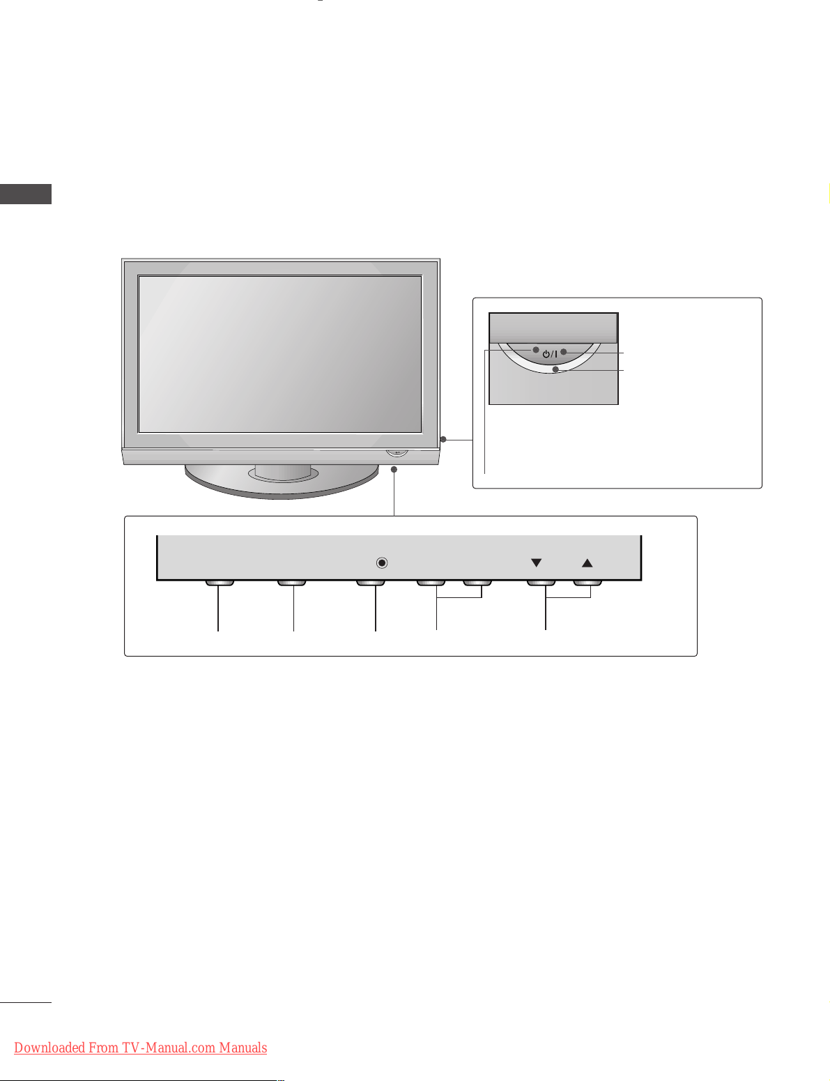
FRONT PANEL CONTROLS
PREPARATION
A
Image shown may differ from your TV.
A
If your TV has a protection film attached, remove the film and then wipe the TV with a polishing cloth.
PLASMA TV Models
PROGRAMMEVOLUMEMENU OKINPUT
Remote Control Sensor
POWER
Power/Standby Indicator
• illuminates red in standby mode.
• illuminates green when the TV is
switched on.
PR
VOL
OK
MENU
INPUT
INPUT
MENU
OK
- +
VOL
PR
Downloaded From TV-Manual.com Manuals
5
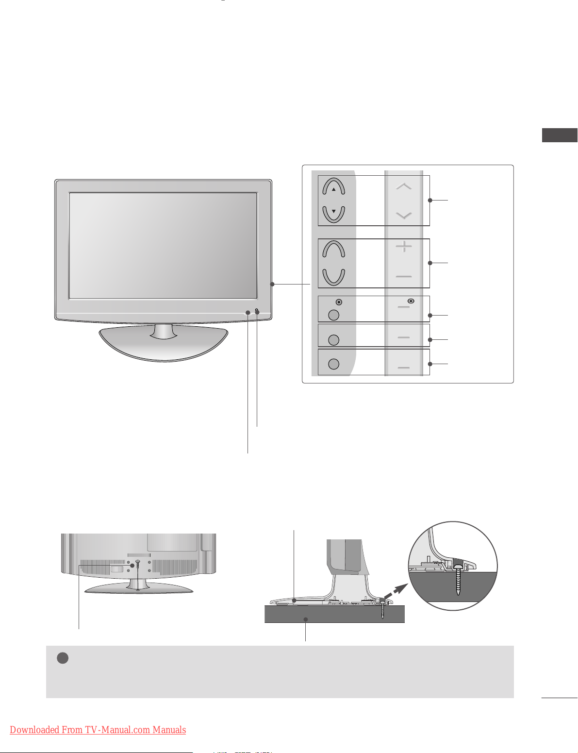
PREPARATION
Intelligent Sensor
Adjusts picture according to the surrounding
conditions. (32/37/42/47/52LG5
***
,
32/37/42/47/52LG75**only)
POWER
Remote Control Sensor
Power/Standby Indicator
• illuminates red in standby mode.
• illuminates blue when the TV is switched on.
Note:
You can adjust
PPoowweerr IInnddiiccaattoorr
in
the
OPTION menu.
PROGRAMME
VOLUME
OK
MENU
INPUT
Attaching the TV to a desk
(Only 32/37/42LG35**, 32/37/42LG55**, 32LG59
**,
32LG75**)
WARNING
!
GG
To prevent TV from falling over, the TV should be securely attached to the floor/wall per installation
instructions. Tipping, shaking, or rocking the machine may cause injury.
The TV must be attached to desk so it cannot be pulled in a forward/backward direction, potentially causing
injury or damaging the product. Use only an attached screw.
1-Screw
(provided as parts of the product)
Desk
Stand
LCD TV Models
or
PR
+
VOL
-
OK
MENU
INPUT
PR
VOL
OK
MENU
INPUT
Downloaded From TV-Manual.com Manuals
6
PREPARATION
PREPARATION
PLASMA
TV Models
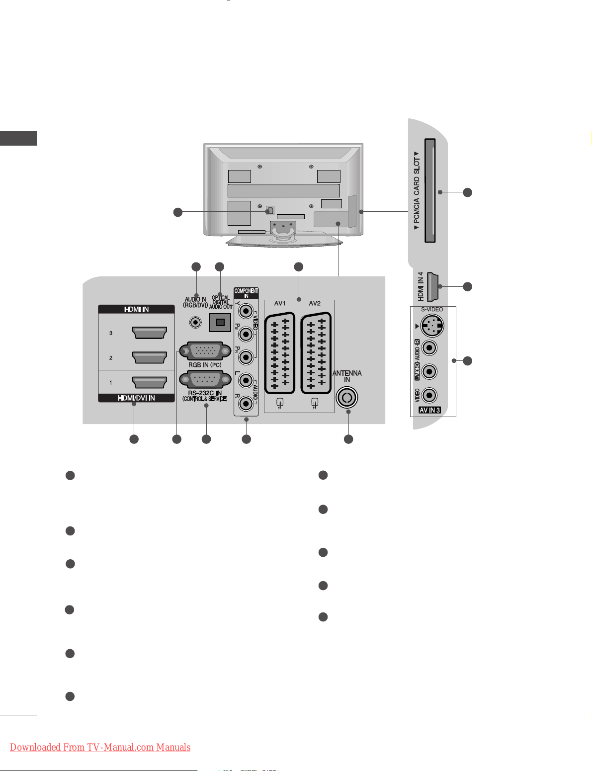
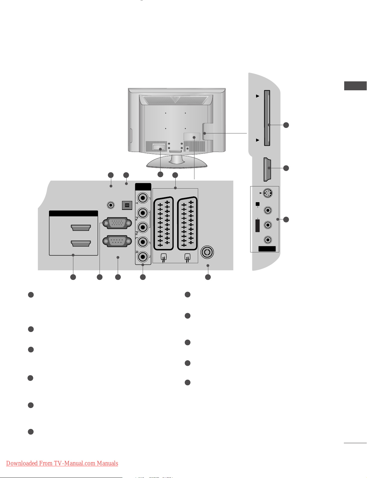
BACK PANEL INFORMATION
A
Image shown may differ from your TV.
Power Cord Socket
This TV operates on an AC power. The voltage is
indicated on the Specifications page. Never
attempt to operate the TV on DC power.
AUDIO IN (RGB/DVI)
Connect the audio from a PC.
OPTICAL DIGITAL AUDIO OUT
Connect digital audio from various types of equipment.
Note: In standby mode, these ports do not work.
Euro Scart Socket (AV1/AV2)
Connect scart socket input or output from an
external device to these jacks.
HDMI IN 1/2/3/4
Connect a HDMI signal to HDMI IN. Or DVI (VIDEO)
signal to HDMI/DVI port with DVI to HDMI cable.
RGB IN (PC)
Connect the output from a PC.
RS-232C IN (CONTROL & SERVICE) PORT
Connect to the RS-232C port on a PC.
Component Input
Connect a component video/audio device to
these jacks.
Antenna Input
Connect RF antenna to this jack.
PCMCIA (Personal Computer Memory Card
International Association) Card Slot
AV (Audio/Video) IN 3
Connect audio/video output from an external
device to these jacks.
S-VIDEO
Connect S-Video out from an S-VIDEO device.
1
2
3
4
5
6
7
8
9
10
11
1
10
5
11
243
95 6 7 8
Downloaded From TV-Manual.com Manuals
RGB IN
(PC)
OPTICAL
DIGITAL
AUDIO OUT
AV 1 AV 2
ANTENNA IN
RS-232C IN
(CONTROL & SERVICE)
AUDIO IN
(RGB/DVI)
HDMI/DVI IN
2
1(DVI)
COMPONENT
IN
VIDEO AUDIO
7
PREPARATION
LCD TV Models
Power Cord Socket
This TV operates on an AC power. The voltage is
indicated on the Specifications page. Never
attempt to operate the TV on DC power.
AUDIO IN (RGB/DVI)
Connect the audio from a PC.
OPTICAL DIGITAL AUDIO OUT
Connect digital audio from various types of equipment.
Note: In standby mode, these ports do not work.
Euro Scart Socket (AV1/AV2)
Connect scart socket input or output from an
external device to these jacks.
HDMI IN 1/2/3
Connect a HDMI signal to HDMI IN. Or DVI (VIDEO)
signal to HDMI/DVI port with DVI to HDMI cable.
RGB IN (PC)
Connect the output from a PC.
RS-232C IN (CONTROL & SERVICE) PORT
Connect to the RS-232C port on a PC.
Component Input
Connect a component video/audio device to
these jacks.
Antenna Input
Connect RF antenna to this jack.
PCMCIA (Personal Computer Memory Card
International Association) Card Slot
AV (Audio/Video) IN 3
Connect audio/video output from an external
device to these jacks.
S-VIDEO
Connect S-Video out from an S-VIDEO device.
1
2
3
4
5
6
7
8
9
10
11
2 43
AUDIO
HDMI IN 3
PCMCIA CARD SLOT
VIDEO
95 6 7 8
10
5
11
1
PCMCIA CARD SLOT
HDMI IN 3
S-VIDEO
R
Downloaded From TV-Manual.com Manuals
AUDIO
L/MONO
VIDEO
AV IN 3
8
PREPARATION
PREPARATION
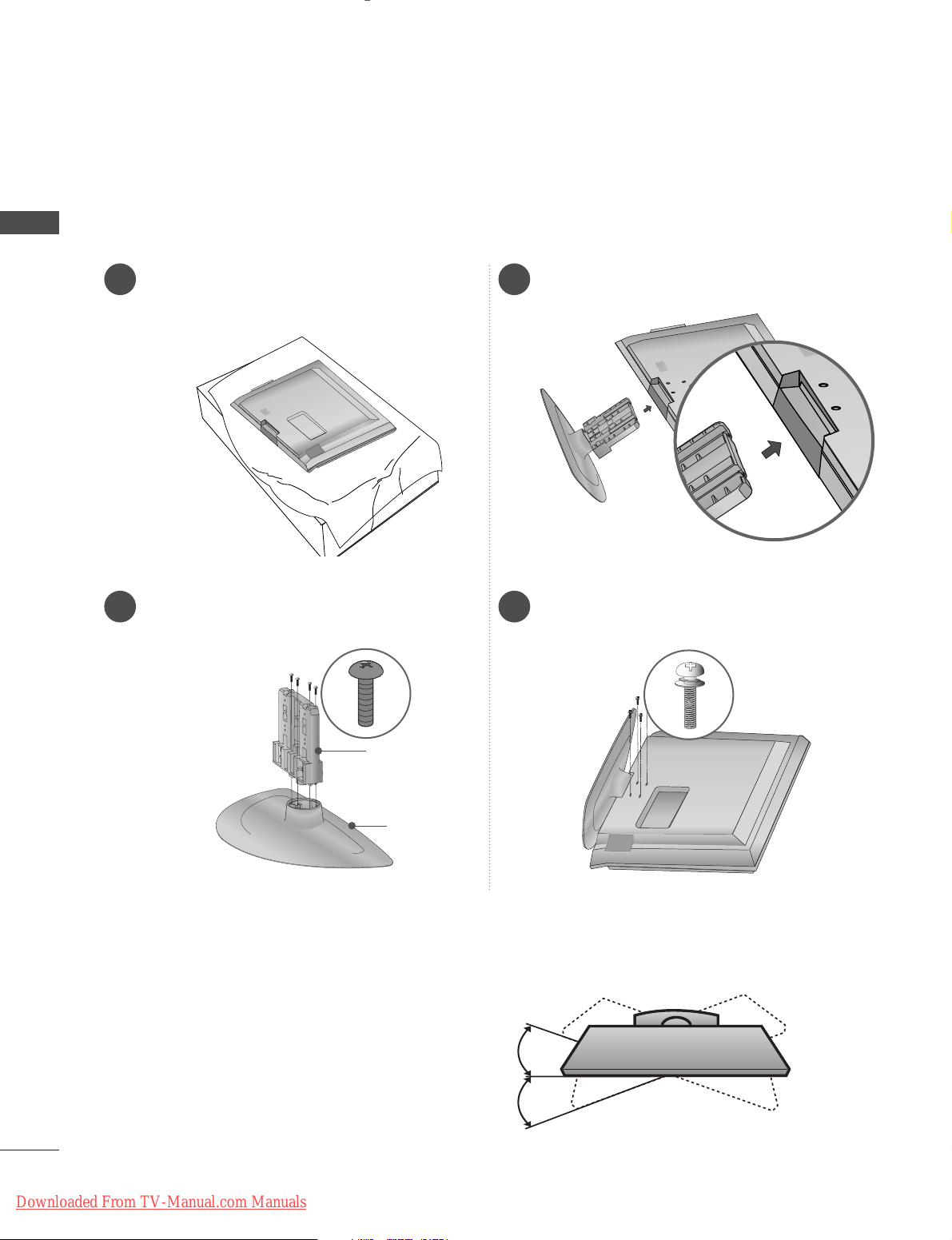
STAND INSTALLATION
(Only 32/37/42LG35**, 32/37/42LG5
***
, 32/37/42LG75**)
1
3
4
Carefully place the TV screen side down on a
cushioned surface to protect the screen from
damage.
2
Assemble the parts of the
ssttaanndd bbooddyy
with
cc oovv eerr bbaassee
of the TV.
Assemble the TV as shown.
Fix the 4 bolts securely using the holes in the
back of the TV.
Swivel Stand
After installing the TV, you can adjust the TV set
manually to the left or right direction by 20 degrees
to suit your viewing position.
Stand Body
Cover Base
A
When assembling the desk type stand, check whether the bolt is fully tightened. (If not tightened fully, the
product can tilt forward after the product installation.) If you tighten the bolt with excessive force, the bolt
can deviate from abrasion of the tightening part of the bolt.
Downloaded From TV-Manual.com Manuals
9
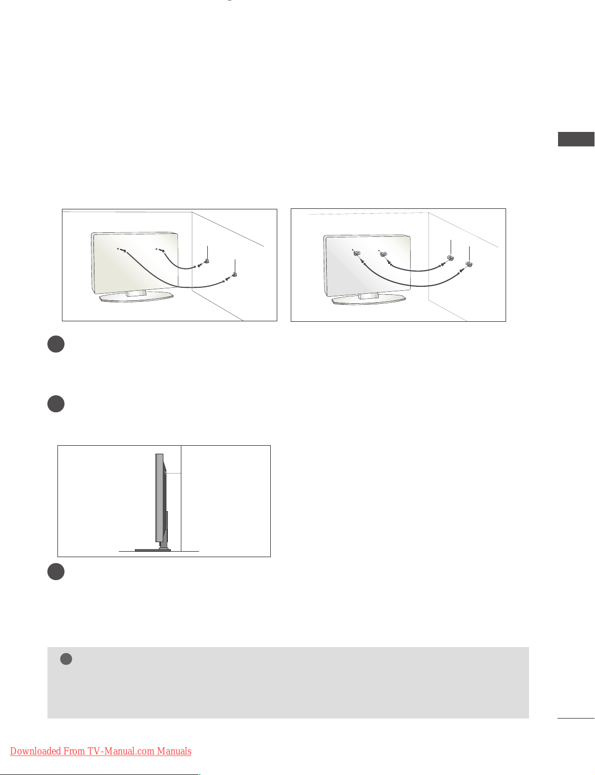
PLEASE SET IT UP CAREFULLY SO THE PRODUCT DOES NOT FALL OVER.
■
You should purchase necessary components to fix the TV to the wall on the market.
■
Position the TV close to the wall to avoid the possibility of it falling when pushed.
■
The instructions shown below are a safer way to set up the TV, which is to fix it to the wall, avoiding the possibility of it falling forwards if pulled. This will prevent the TV from falling forward and causing injury. This will
also prevent the TV from damage. Ensure that children do not climb or hang from the TV.
NOTE
!
G
When moving the TV undo the cords first.
G
Use a platform or cabinet strong and large enough to support the size and weight of the TV.
G
To use the TV safely make sure that the height of the bracket on the wall and on the TV is the same.
3
1
2
Use the eye-bolts or TV brackets/bolts to fix the TV to the wall as shown in the picture.
(If your TV has bolts in the eyebolts, loosen these bolts.)
* Insert the eye-bolts or TV brackets/bolts and tighten them securely in the upper holes.
Secure the wall brackets with the bolts on the wall. Match the height of the bracket that is mounted
on the wall.
3
Use a sturdy rope to tie the TV. It is safer to tie the rope so it becomes horizontal between the wall
and the TV.
PREPARATION
2
1
2
1
Downloaded From TV-Manual.com Manuals
10
PREPARATION
PREPARATION
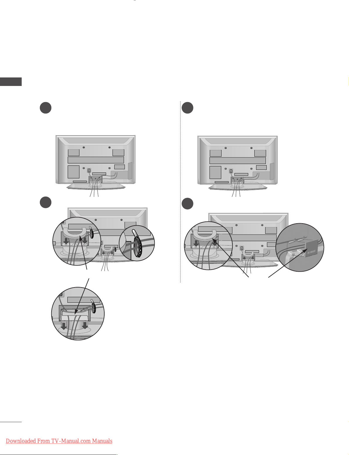
BACK COVER FOR WIRE ARRANGEMENT
Connect the cables as necessary.
To connect additional equipment, see the
EExxtteerrnnaa ll eeqq uuiippmmeenntt SSee ttuupp
section.
1
Install the
CCAABBLLEE MMAANNAAGGEEMMEENNTT CCLLIIPP
as shown.
2
■
Image shown may differ from your TV.
CABLE MANAGEMENT CLIP
Plasma TV models
Connect the cables as necessary.
To connect additional equipment, see the
EExxtteerrnnaa ll eeqq uuiippmmeenntt SSee ttuupp
section.
1
Install the
CCAABBLLEE MMAANNAAGGEEMMEENNTT CCLLIIPP
as shown.
2
CABLE MANAGEMENT CLIP
42/50PG25**, 42/50PG35**,
42PG65**, 50PG45
**
50PG65
**,
50PG75
**
Fix the
CC aabbllee HHoollddeerr
as
shown and bundle the
cables.
42/50PG25**, 42/50PG35**,
50PG45
**
Downloaded From TV-Manual.com Manuals
11
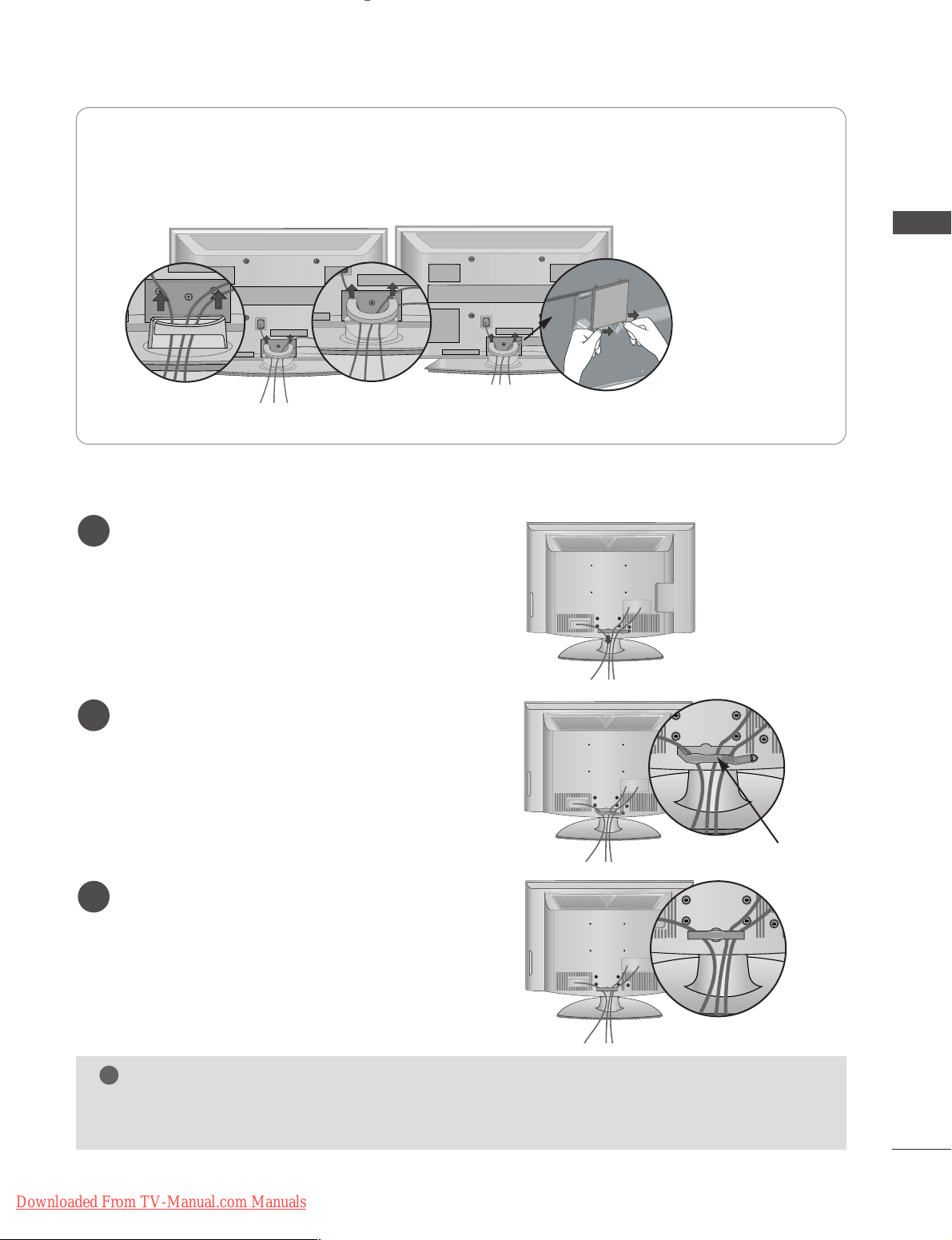
LCD TV models
Connect the cables as necessary.
To connect additional equipment, see the
External Equipment Setup section of the
manual.
1
Open the
CC AABBLLEE MMAANNAAGG EEMMEENNTT CC LLII PP
as
shown and manage the cables.
2
CABLE MANAGEMENT CLIP
Fit the
CC AABBLLEE MMAANNAAGG EEMMEENNTT CC LLII PP
as
shown.
3
PREPARATION
Hold the
CC AABBLLEE MMAANNAAGG EEMMEENNTT CC LLII PP
with both hands and pull it upward.
For the 42PG65**model, press the center of the
CC AABBLLEE MMAANNAAGGEEMMEE NNTT CC LLIIPP
and then lift up it.
NOTE
!
GG
Do not use the CABLE MANAGEMENT CLIP to lift the TV.
- If the TV is dropped, you may be injured or the TV may be damaged.
HHooww ttoo rreemmoovvee tthhee ccaabbllee mmaannaaggeemmeenntt cclliipp
50PG65**/50PG75
**
42PG65
**
42/50PG25**,
42/50PG35**, 50PG45
**
Separate CABLE
MANAGEMENT from
TV by pressing two
latches.
Downloaded From TV-Manual.com Manuals
12
PREPARATION
PREPARATION
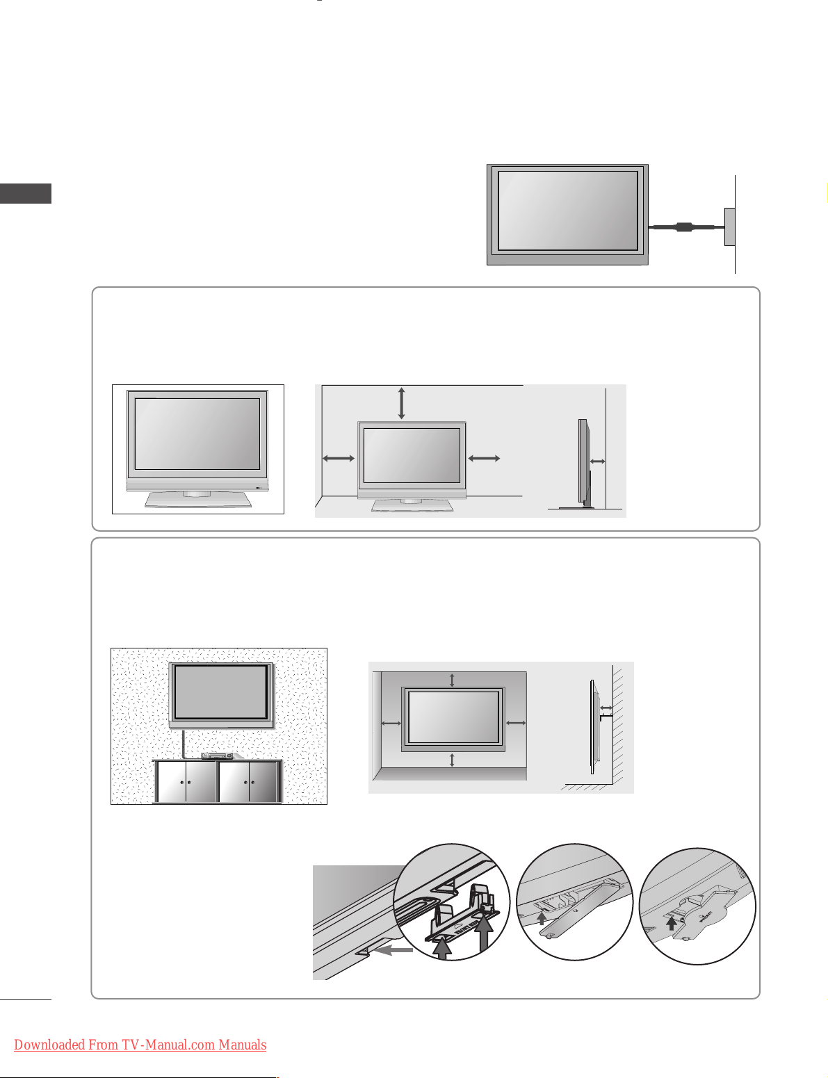
DESKTOP PEDESTAL INSTALLATION
For adequate ventilation allow a clearance of 4” (10cm) all around the TV.
EARTHING
Ensure that you connect the earth wire to prevent possible
electric shock. Do not try to earth the TV by connecting it
to telephone wires, lightening rods or gas pipes.
Power Supply
Circuit
breaker
■
The TV can be installed in various ways such as on a wall or on a desktop etc.
■
The TV is designed to be mounted horizontally.
4 inches
4 inches 4 inches 4 inches
WALL MOUNT: HORIZONTAL INSTALLATION
For adequate ventilation allow a clearance of 4” (10cm) all around the TV. We recommend that you use a
wall mounting bracket of LG brand when mounting the TV to a wall.
4 inches
4 inches
4 inches 4 inches
4 inches
When installing the wall-mounted
unit, use the protection cover for
desk-type stand installation. Insert
the
PPRROOTTEECCTTII OONN CCOOVVEERR
into
the TV until clicking sound.
Not using the desk-type stand
A
Image shown may differ from your TV.
< PLASMA TV >
< LCD TV >
or
R
Downloaded From TV-Manual.com Manuals

13
ANTENNA IN
ANTENNA IN
■
For optimum picture quality, adjust antenna direction.
■
An antenna cable and converter are not supplied.
■
To prevent damage do not connect to the mains outlet until all connections are made between the devices.
Multi-family Dwellings/Apartments
(Connect to wall antenna socket)
Single-family Dwellings /Houses
(Connect to wall jack for outdoor antenna)
Outdoor
Antenna
(VHF, UHF)
Wall
Antenna
Socket
RF Coaxial Wire (75 ohm)
ANTENNA CONNECTION
Antenna
UHF
Signal
Amplifier
VHF
■
In poor signal areas, to achieve better picture quality it may be necessary to install a signal amplifier to the
antenna as shown above.
■
If signal needs to be split for two TVs,use an antenna signal splitter for connection.
AV IN 3
L/MONO
R
AUDIO
VIDEO
S-VIDEO
PREPARATION
Downloaded From TV-Manual.com Manuals
14
EXTERNAL EQUIPMENT SETUP
EXTERNAL EQUIPMENT SETUP
HD RECEIVER SETUP
■
This TV can receive Digital RF/Cable signals without an external digital set-top box. However, if you do receive
Digital signals from a digital set-top box or other digital external device, refer to the diagram as shown below.
RGB IN
(PC)
OPTICAL
DIGITAL
AUDIO OUT
AV
RS-232C IN
(CONTROL & SERVICE)
AUDIO IN
(RGB/DVI)
HDMI/DVI IN
2
1(DVI)
COMPONENT
IN
VIDEO AUDIO
Connecting with a component cable
Connect the video outputs (Y, P
B, PR
)
of the digital set
top box to the
CC OOMMPPOO NNEENNTT IINN VVII DDEEOO
jacks on
the TV.
Connect the audio output of the digital set-top box to
the
CC OOMMPPOO NNEENNTT IINN AAUUDDIIOO
jacks on the TV.
Turn on the digital set-top box.
(
Refer to the owner’s manual for the digital set-top
box.
)
Select COMPONENT input source using the
II NNPPUU TT
button on the remote control.
2
3
4
1
Signal
480i/576i
480p/576p
720p/1080i
10 8 0 p
Component
Yes
Yes
Yes
Yes
(Only 32LG59**,
37/42/47/52LG55**,
32/37/42/47/52LG75**,
50PG45**, 50PG75**)
HDMI1/2/3/4
(HDMI4 : only PLASMA TV Models)
No
Yes
Yes
Yes
1 2
■
To avoid damaging any equipment, never plug in any power cords until you have finished connecting all equipment.
■
This section on EXTERNAL EQUIPMENT SETUP mainly uses diagrams for the LCD TV models.
Downloaded From TV-Manual.com Manuals
15
RGB IN
(PC)
RS-232C IN
(CONTROL & SERVICE)
HDMI/DVI IN
2
1(DVI)
VIDEO AUDIO
HDMI-DTV OUTPUT
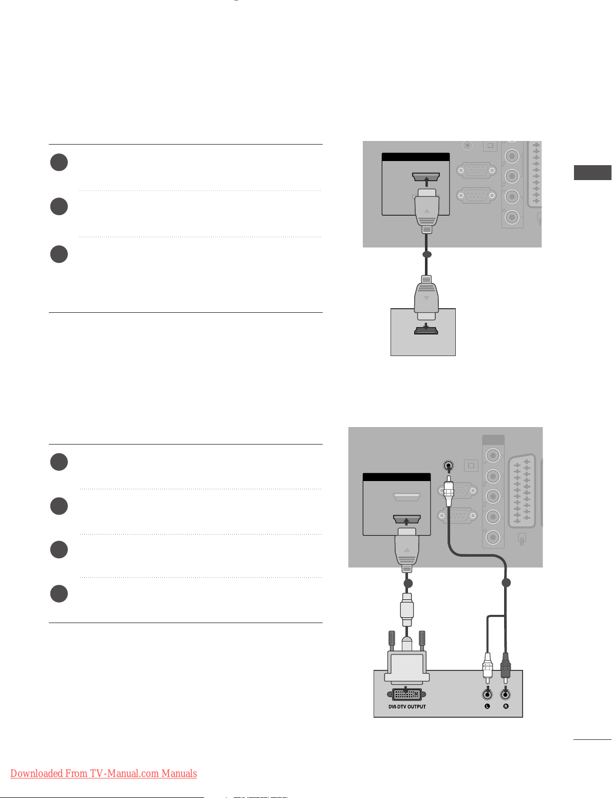
Connecting a set-top box with an HDMI cable
Connect the digital set-top box to
HHDDMMII IINN 22
jack on
the TV.
Turn on the digital set-top box.
(
Refer to the owner’s manual for the digital set-top box.
)
Select HDMI2 input source using the
II NNPPUUTT
button
on the remote control.
If connected to
HHDDMMII IINN 33
(or
HHDDMMII IINN 44
) jack,
select HDMI3 (or HDMI4) input source.
2
3
1
1
RGB IN
(PC)
OPTICAL
DIGITAL
AUDIO OUT
AV 1
RS-232C IN
(CONTROL & SERVICE)
AUDIO IN
(RGB/DVI)
HDMI/DVI IN
2
1(DVI)
COMPONENT
IN
VIDEO AUDIO
1
2
Connect the digital set-top box to
HHDDMMII // DDVV II IINN
11((DDVVII))
jack on the TV.
Connect the audio output of the digital set-top box to
the
AA UUDDIIOO II NN ((RR GGBB//DDVVII))
jack on the TV.
Turn on the digital set-top box. (Refer to the owner’s
manual for the digital set-top box.
)
Select HDMI1 input source using the
II NNPPUUTT
button
on the remote control.
2
3
4
1
Connecting with a HDMI to DVI cable
EXTERNAL EQUIPMENT SETUP
Downloaded From TV-Manual.com Manuals

16
EXTERNAL EQUIPMENT SETUP
EXTERNAL EQUIPMENT SETUP
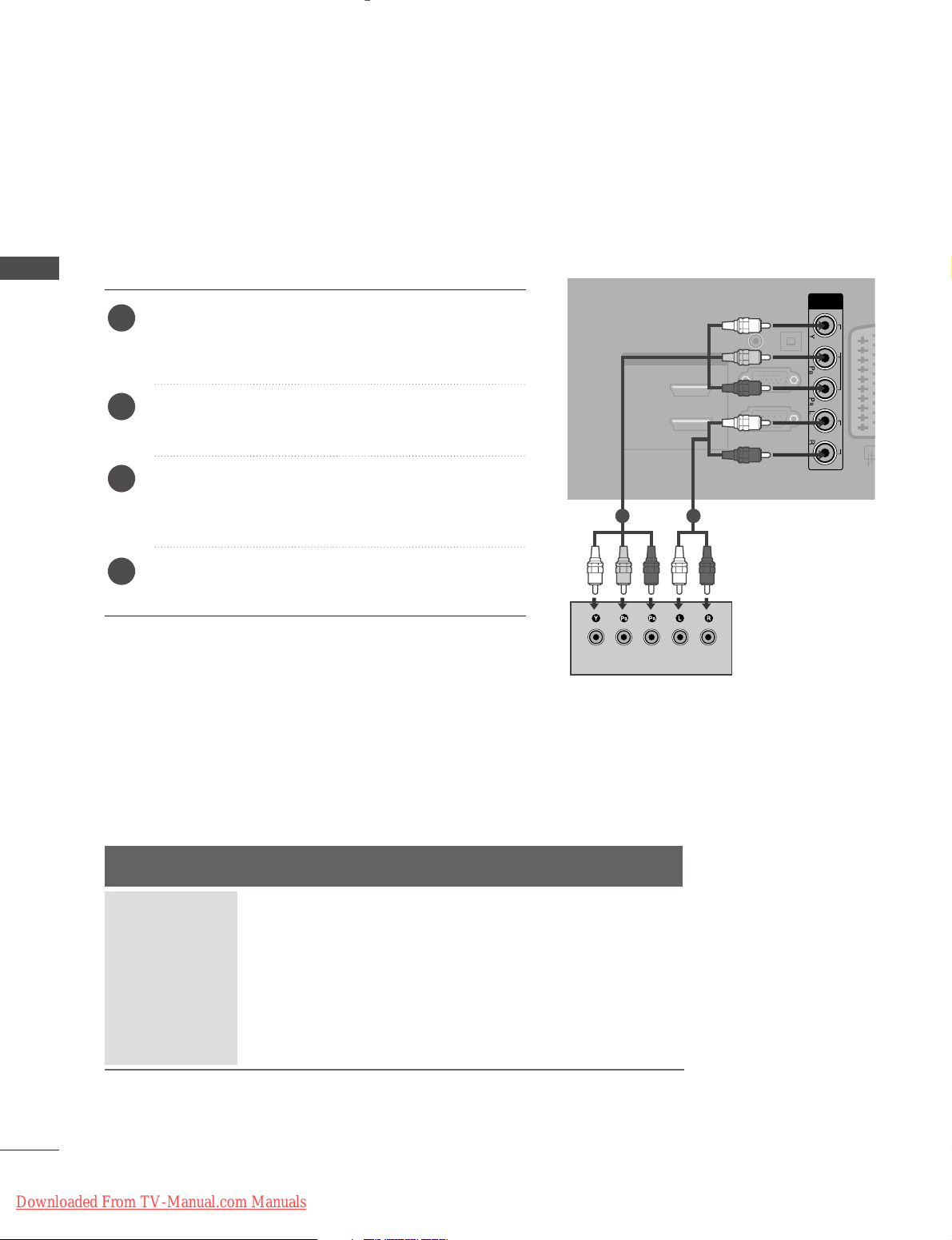
DVD SETUP
Connecting with a component cable
Component Input ports
To achieve better picture quality, connect a DVD player to the component input ports as shown below.
Component ports on the TV
YPBP
R
Video output ports
on DVD player
Y
Y
Y
Y
P
B
B-Y
Cb
Pb
P
R
R-Y
Cr
Pr
Connect the video outputs (Y, PB, PR
)
of the DVD to the
CC OOMMPPOO NNEENNTT IINN VV II DDEEOO
jacks on the TV.
Connect the audio outputs of the DVD to the
CC OOMMPPOO NNEENNTT IINN AA UUDDIIOO
jacks on the TV.
Turn on the DVD player, insert a DVD.
Select COMPONENT input source using the
II NNPPUUTT
button on the remote control.
Refer to the DVD player's manual for operating
instructions.
2
3
4
5
1
RGB IN
(PC)
OPTICAL
DIGITAL
AUDIO OUT
AV
RS-232C IN
(CONTROL & SERVICE)
AUDIO IN
(RGB/DVI)
HDMI/DVI IN
2
1(DVI)
COMPONENT
IN
VIDEO AUDIO
1 2
Downloaded From TV-Manual.com Manuals
17
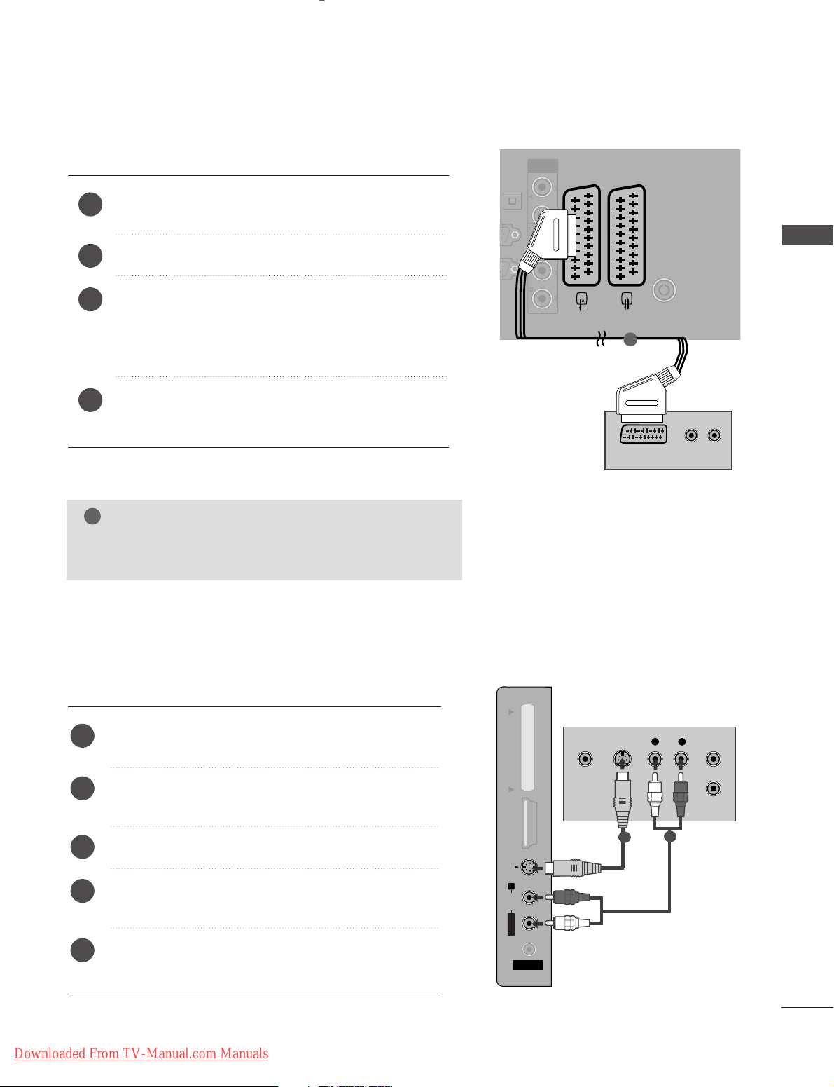
Connecting with a Euro scart
Connect the Euro scart socket of the DVD to the
AA VV 11
Euro scart socket on the TV.
Turn on the DVD player, insert a DVD.
Select AV 1 input source using the
II NNPPUUTT
button on
the remote control.
If connected to AV2 Euro scart socket, select AV 2
input source.
Refer to the DVD player's manual for operating
instructions.
2
3
4
1
(PC)
OPTICAL
DIGITAL
AV 1 AV 2
ANTENNA IN
COMPONENT
IN
VIDEO AUDIO
(R) AUDIO (L)
AUDIO/
VIDEO
1
NOTE
!
GG
If you want to use the EURO scart cable, you have to use
the signal shielded Euro scart cable.
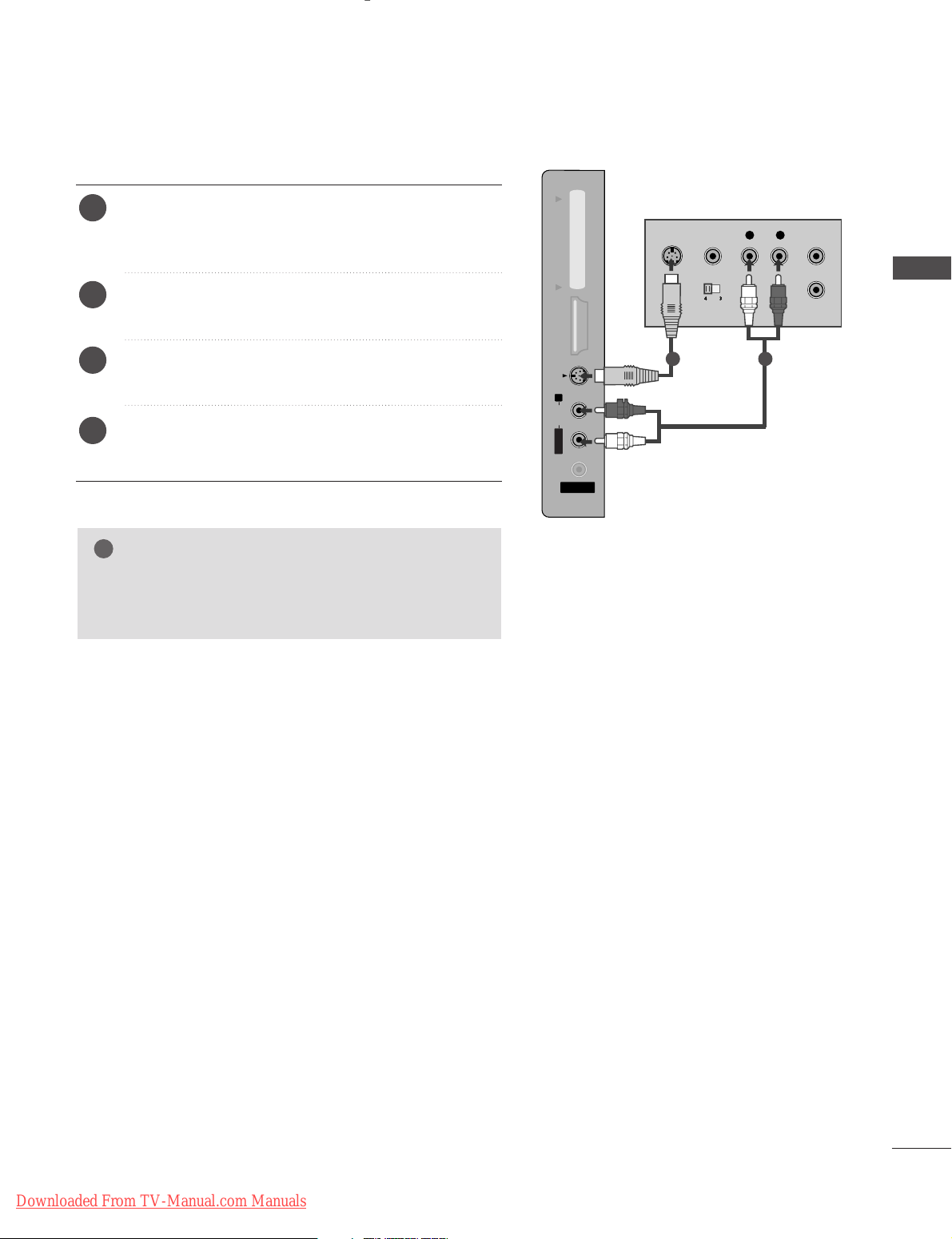
Connecting with a S-Video cable
AV IN 3
L/L/MONOMONO
R
AUDIOAUDIO
HDMI IN 3HDMI IN 3 PCMCIA CARD SLOT PCMCIA CARD SLOT
VIDEOVIDEO
S-VIDEO
L R
S-VIDEOVIDEO
OUTPUT
SWITCH
ANT IN
ANT OUT
Connect the S-VIDEO output of the DVD to the
SS --
VV IIDD EEOO
input on the TV.
Connect the audio outputs of the DVD to the
AA UU DDIIOO
input jacks on the TV.
Turn on the DVD player, insert a DVD.
Select AV 3 input source using the INPUT button on
the remote control.
Refer to the DVD player's manual for operating
instructions.
2
3
4
5
1
1
2
EXTERNAL EQUIPMENT SETUP
Downloaded From TV-Manual.com Manuals
18
EXTERNAL EQUIPMENT SETUP
EXTERNAL EQUIPMENT SETUP
RGB IN
(PC)
DIGITAL
AUDIO OUT
AV
RS-232C IN
(CONTROL & SERVICE)
AUDIO IN
(RGB/DVI)
HDMI/DVI IN
2
1(DVI)
IN
VIDEO AUDIO
AV IN 3
L/MONO
R
AUDIO
HDMI IN 3 PCMCIA CARD SLOT
VIDEO
S-VIDEO
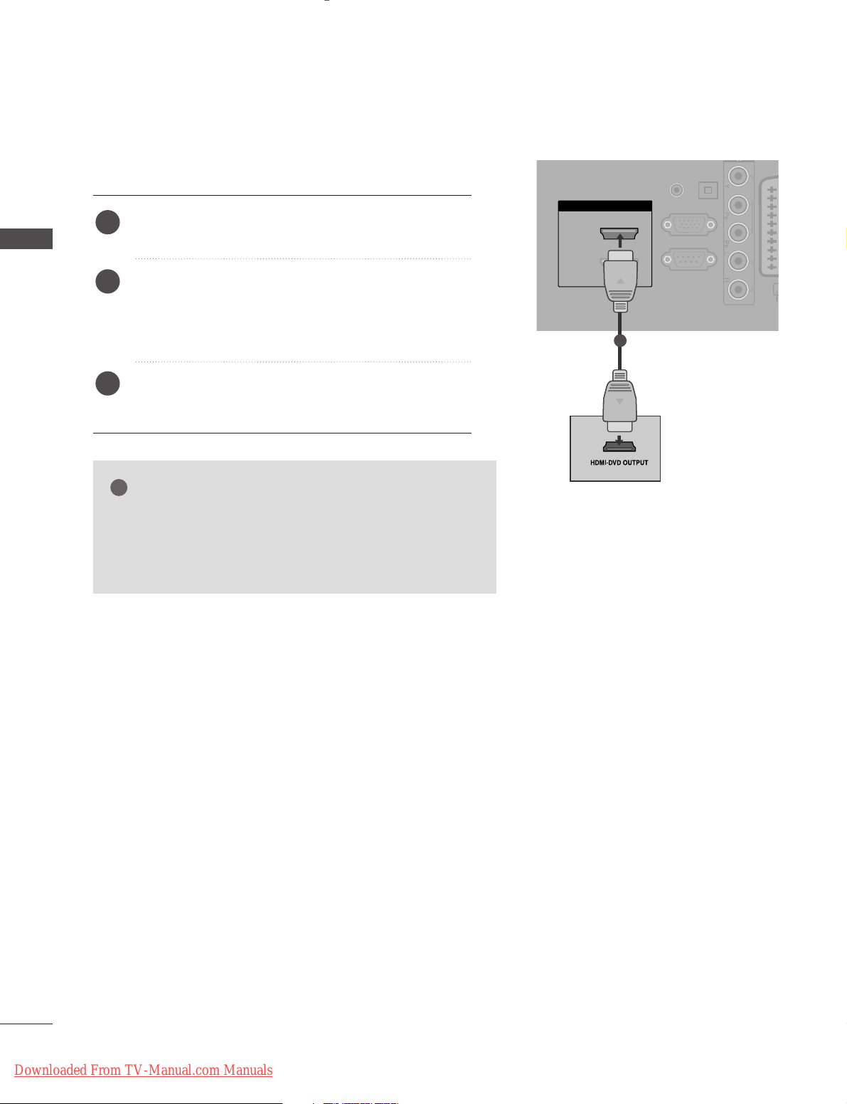
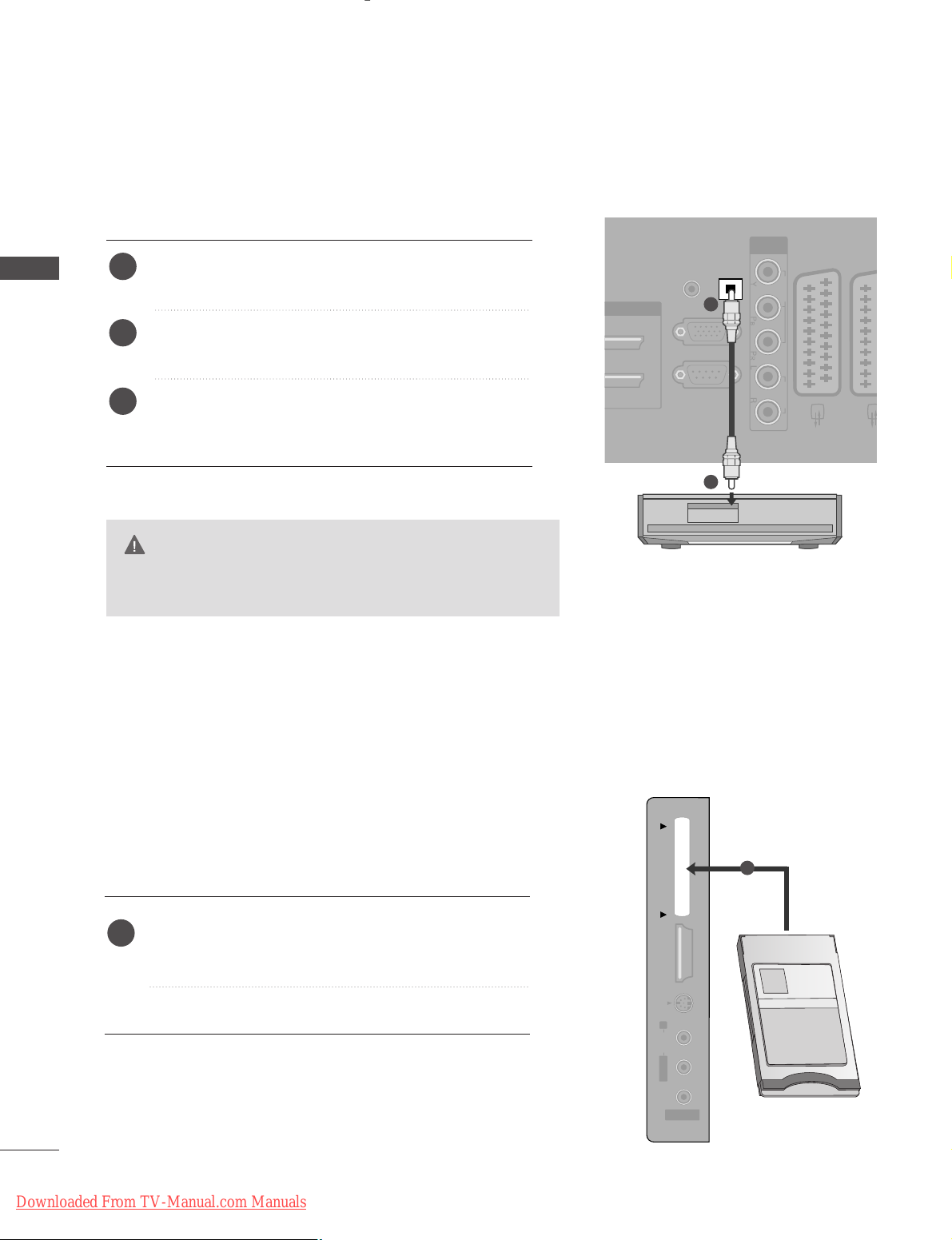
Connecting HDMI cable
Connect the HDMI output of the DVD to the
HHDDMMII
II NN 22
jack on the set.
Select HDMI2 input source using the
II NNPPUUTT
button
on the remote control.
If connected to
HHDDMMII IINN 33
(or
HHDDMMII IINN 44
) jack,
select HDMI3 (or HDMI4) input source.
Refer to the DVD player's manual for operating
instructions.
1
2
3
GG
The TV can receive video and audio signals simultaneously
when using a HDMI cable.
GG
If the DVD does not support Auto HDMI, you must set the
output resolution appropriately.
NOTE
!
1
Downloaded From TV-Manual.com Manuals
19
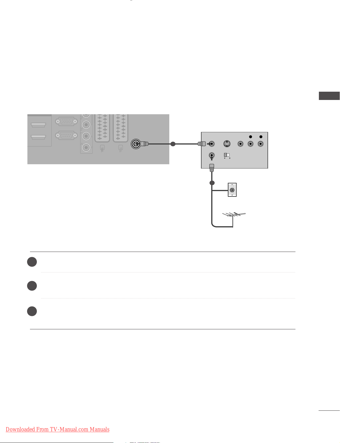
When connecting with a RF Cable
■
To avoid picture noise (interference), allow adequate distance between the VCR and TV.
■
If 4:3 picture format is used for an extended period the fixed images on the sides of the screen may remain
visible.
RGB IN
(PC)
ANTENNA IN
RS-232C IN
(CONTROL & SERVICE)
MI/DVI IN
AUDIO
AV IN 3
L/MONO
R
AUDIO
HDMI IN 3 PCMCIA CARD SLOT
VIDEO
S-VIDEO
OUTPUT
SWITCH
ANT IN
R
S-VIDEO VIDEO
ANT OUT
L
Wall Jack
Antenna
Connect the
AA NNTT OO UU TT
socket of the VCR to the
AA NNTTEE NNNNAA IINN
socket on the TV.
Connect the antenna cable to the
AA NNTT IINN
socket of the VCR.
Press the PLAY button on the VCR and match the appropriate channel between the TV and VCR for
viewing.
VCR SETUP
1
2
2
3
1
EXTERNAL EQUIPMENT SETUP
Downloaded From TV-Manual.com Manuals
20
EXTERNAL EQUIPMENT SETUP
EXTERNAL EQUIPMENT SETUP
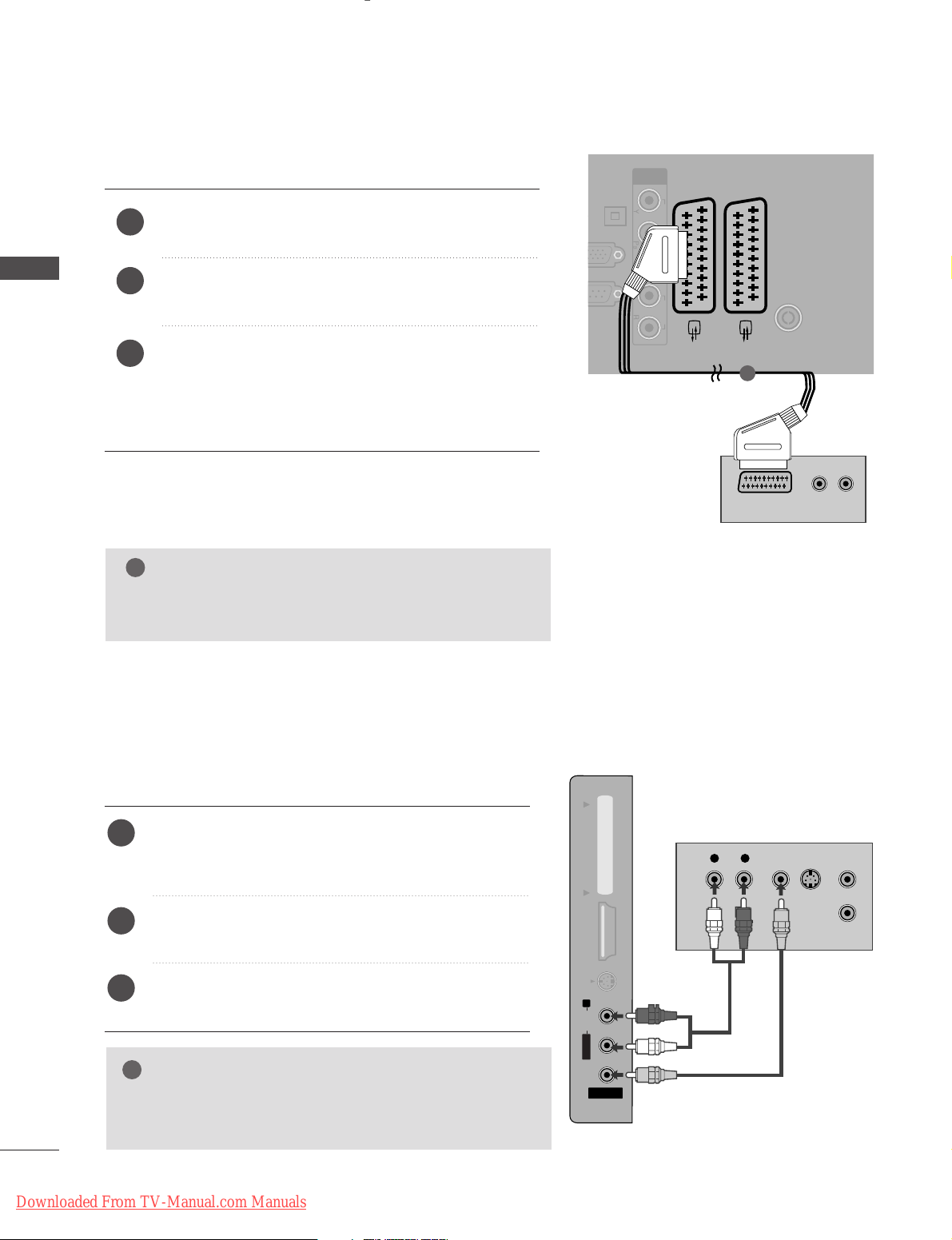
Connecting with a Euro scart
Connect the Euro scart socket of the VCR to the
AA VV 11
Euro scart socket on the TV.
Insert a video tape into the VCR and press PLAY on
the VCR. (Refer to the VCR owner’s manual.)
Select AV 1 input source using the
II NNPPUUTT
button on
the remote control.
If connected to
AA VV22
Euro scart socket, select AV 2
input source.
2
3
1
(PC)
OPTICAL
DIGITAL
AUDIO OUT
AV 1 AV 2
ANTENNA IN
232C IN
L & SERVICE)
IN
COMPONENT
IN
VIDEO AUDIO
(R) AUDIO (L)
AUDIO/
VIDEO
1
NOTE
!
GG
If you want to use the EURO scart cable, you have to use
the signal shielded Euro scart cable.
Connecting with a RCA cable
AV IN 3
L/L/MONOMONO
R
AUDIOAUDIO
HDMI IN 3HDMI IN 3 PCMCIA CARD SLOT PCMCIA CARD SLOT
VIDEOVIDEO
S-VIDEO
L
R
S-VIDEO
VIDEO
OUTPUT
SWITCH
ANT IN
ANT OUT
Connect the
AA UU DD II OO/VV IIDD EEOO
jacks between TV and
VCR. Match the jack colours (Video = yellow, Audio Left
= white, and Audio Right = red)
Insert a video tape into the VCR and press PLAY on
the VCR. (Refer to the VCR owner’s manual.
)
Select AV 3 input source using the
II NNPPUUTT
button on
the remote control.
1
2
3
GG
If you have a mono VCR, connect the audio cable from the
VCR to the
AA UUDDIIOO LL//MMOONNOO
jack of the TV.
NOTE
!
Downloaded From TV-Manual.com Manuals
21
GG
If both S-VIDEO and VIDEO sockets have been
connected to the S-VHS VCR simultaneously, only
the S-VIDEO can be received.
NOTE
!
AV IN 3
L/L/MONOMONO
R
AUDIOAUDIO
HDMI IN 3HDMI IN 3 PCMCIA CARD SLOT PCMCIA CARD SLOT
VIDEOVIDEO
S-VIDEO
AV IN 3
L/ MONO
R
AUDIO
HDMI IN 3 PCMCIA CARD SLOT
VIDEO
S-VIDEO
L
R
S-VIDEO
VIDEO
OUTPUT
SWITCH
ANT IN
ANT OUT
Connecting with a S-Video cable
Connect the S-VIDEO output of the VCR to the S VIDEO input on the TV. The picture quality is improved;
compared to normal composite (RCA cable) input.
Connect the audio outputs of the VCR to the AUDIO
input jacks on the TV.
Insert a video tape into the VCR and press PLAY on the
VCR. (Refer to the VCR owner’s manual.)
Select AV 3 input source using the
IINNPPUUTT
button on the
remote control.
2
3
4
1
1 2
EXTERNAL EQUIPMENT SETUP
Downloaded From TV-Manual.com Manuals
22
EXTERNAL EQUIPMENT SETUP
EXTERNAL EQUIPMENT SETUP
DIGITAL AUDIO OUT SETUP
- Sending the TV’s audio signal to external audio equipment via
the Digital Audio Output (Optical) port.
G
Do not look into the optical output port. Looking at the
laser beam may damage your vision.
CAUTION
RGB IN
(PC)
OPTICAL
DIGITAL
AUDIO OUT
AV 1 AV
RS-232C IN
(CONTROL & SERVICE)
AUDIO IN
(RGB/DVI)
COMPONENT
IN
VIDEO AUDIO
Connect one end of an optical cable to the TV Digital
Audio (Optical)Output port.
Connect the other end of the optical cable to the
digital audio (optical)input on the audio equipment.
Set the “TV Speaker option - Off ” in the AUDIO
menu.(
G
pp..7733
). Refer to the external audio equipment
instruction manual for operation.
2
3
1
1
2
Insert the CI Module to
PP CC MMCC II AA
(Personal Computer
Memory Card International Association)
CC AARRDD SS LL OOTT
of TV as shown.
For further information, see p.43.
1
INSERTION OF CI MODULE
AV IN 3
L/L/MONOMONO
R
AUDIOAUDIO
HDMI IN 3HDMI IN 3 PCMCIA CARD SLOT PCMCIA CARD SLOT
VIDEOVIDEO
S-VIDEO
TVTV
-- TToo vviieeww tthhee eennccrryyppttee dd ((ppaayy )) ss eerrvviicceess iinn ddiiggii ttaall TTVV
mm oo dd ee..
1
Downloaded From TV-Manual.com Manuals
23
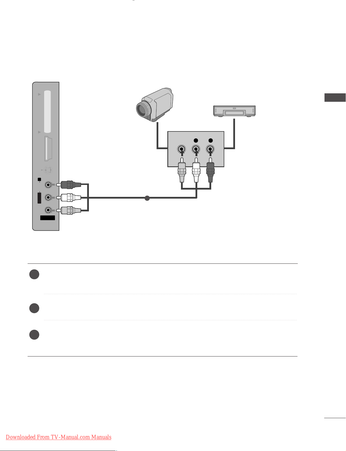
OTHER A/V SOURCE SETUP
Connect the
AA UU DDIIOO/VV IIDD EEOO
jacks between TV and external equipment. Match the jack colors
.
(
Video = yellow, Audio Left = white, and Audio Right = red
)
Select AV 3 input source using the
II NNPPUUTT
button on the remote control.
Operate the corresponding external equipment.
Refer to external equipment operating guide.
AV IN 3V IN 3
L/MONOMONO
R
AUDIOAUDIO
HDMI IN 3HDMI IN 3 PCMCIA CARD SLOT PCMCIA CARD SLOT
VIDEOVIDEO
S-VIDEOS-VIDEO
L R
VIDEO
Camcorder
Video Game Set
1
1
2
3
EXTERNAL EQUIPMENT SETUP
Downloaded From TV-Manual.com Manuals
24
EXTERNAL EQUIPMENT SETUP
EXTERNAL EQUIPMENT SETUP
PC SETUP
This TV provides Plug and Play capability, meaning that the PC adjusts automatically to the TV's settings.
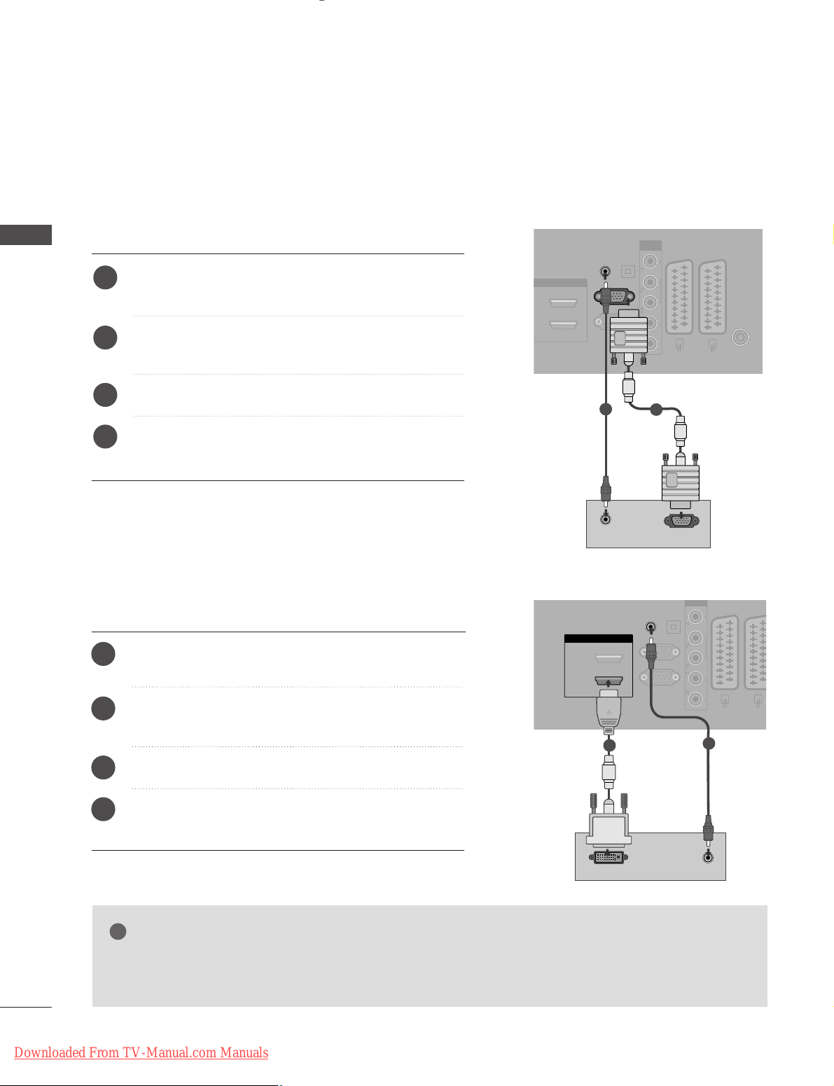
Connecting with a D-sub 15 pin cable
RGB IN
(PC)
OPTICAL
DIGITAL
AUDIO OUT
AV 1 AV 2
ANTENNA IN
RS-232C IN
(CONTROL & SERVICE)
AUDIO IN
(RGB/DVI)
HDMI/DVI IN
)
COMPONENT
IN
VIDEO AUDIO
RGB OUTPUT
AUDIO
Connect the RGB output of the PC to the RGB IN
(PC) jack on the TV.
Connect the PC audio output to the AUDIO IN
(RGB/DVI) jack on the TV.
Turn on the PC and the TV.
Select RGB input source using the INPUT button on
the remote control.
2
3
4
1
Connecting with a HDMI to DVI cable
GG
If the PC has a DVI output and no HDMI output, a separated audio connection is necessary.
GG
If the PC does not support Auto DVI, you need to set the output resolution appropriately.
NOTE
!
RGB IN
(PC)
OPTICAL
DIGITAL
AUDIO OUT
AV 1 AV 2
RS-232C IN
(CONTROL & SERVICE)
AUDIO IN
(RGB/DVI)
HDMI/DVI IN
2
1(DVI)
COMPONENT
IN
VIDEO AUDIO
AUDIO
DVI-PC OUTPUT
Connect the DVI output of the PC to the
HHDDMMII// DDVV II
IINN 11((DD VVII))
jack on the TV.
Connect the PC audio output to the
AA UUDDIIOO IINN
(( RRGGBB//DDVV II ))
jack on the TV.
Turn on the PC and the TV.
Select HDMI1 input source using the INPUT button
on the remote control.
2
3
4
1
2
1
1
2
Downloaded From TV-Manual.com Manuals

25
NOTE
!
G
To enjoy vivid picture and sound, connect a PC to
the TV.
G
Avoid keeping a fixed image on the TV’s screen for
prolonged periods of time. The fixed image may
become permanently imprinted on the screen; use
a screen saver when possible.
G
Connect the PC to the RGB (PC) or HDMI IN (or
HDMI/DVI IN) port of the TV; change the resolution.
G
There may be interference relating to resolution,
vertical pattern, contrast or brightness in PC
mode. Change the PC mode to another resolution
or change the refresh rate to another rate or
adjust the brightness and contrast on the menu
until the picture is clear. If the refresh rate of the
PC graphic card can not be changed, change the
PC graphic card or consult the manufacturer of
the PC graphic card.
G
The synchronization input waveform for
Horizontal and Vertical frequencies are separate.
G
In PLASMA TV models, we recommend using
1024x768, 60Hz for the PC mode, these should
provide the best picture quality.
G
Connect the signal cable from the monitor output
port of the PC to the RGB (PC) port of the TV or
the signal cable from the HDMI output port of
the PC to the HDMI IN (or HDMI/DVI IN) port
on the TV.
G
Connect the audio cable from the PC to the
Audio input on the TV. (Audio cables are not
included with the TV).
G
If using a sound card, adjust PC sound as
required.
G
This TV uses a VESA Plug and Play Solution. The
TV provides EDID data to the PC system with a
DDC protocol. The PC adjusts automatically when
using this TV.
G
DDC protocol is preset for RGB (Analog RGB),
HDMI (Digital RGB) mode.
G
If required, adjust the settings for Plug and Play
functionality.
G
If the graphic card on the PC does not output
analogue and digital RGB simultaneously, connect
only one of either RGB or HDMI IN (or HDMI/DVI
IN) to display the PC output on the TV.
G
If the graphic card on the PC does output analogue and digital RGB simultaneously, switch the
TV to either RGB or HDMI; (the other mode is set
to Plug and Play automatically by the TV.)
G
DOS mode may not work depending on the video
card if you use a HDMI to DVI cable.
G
If you use too long an RGB[PC] cable, there may
be interference on the screen. We recommend
using under 5m of cable. This provides the best
picture quality.
EXTERNAL EQUIPMENT SETUP
Downloaded From TV-Manual.com Manuals
26
EXTERNAL EQUIPMENT SETUP
EXTERNAL EQUIPMENT SETUP
Supported Display Resolution
Resolution
720x400
640x480
Horizontal
Frequency(kHz)
Vertical
Frequency(Hz)
800x600
832x624
1024x768
1280x768
1360x768
RGB[PC] / HDMI[PC] mode
1600x1200
640x480
720x480
720x576
1280x720
1920x1080
59.94
60.00
59.94
60.00
50.00
50.00
59.94
60.00
59.94
60.00
50.00
24.00
30.00
50.00
59.94
60.00
31.469
31.469
31.47
31.50
31.25
37. 50
44.96
45.00
33.72
33.75
28.125
27.00
33.75
56.25
67. 433
67. 500
HDMI[DTV] mode
Resolution
Horizontal
Frequency(kHz)
Vertical
Frequency(Hz)
1280x1024
1400x1050
31.468
31.469
37. 500
37. 879
46.875
49.725
48.363
56.476
60.023
47. 693
47. 649
47. 649
66.647
63.595
65.150
74.077
70.08
59.94
75.00
60.31
75.00
74.55
60.00
70.00
75.03
59.99
59.94
59.94
59.988
60.00
60.00
60.00
GG
It is not supported to 1600x1200, 60Hz in RGB[PC] mode.
GG
42/50PG65**is not supported to 1920x1080 in RGB[PC]/HDMI[PC] mode.
GG
PLASMA TV is not supported to 1366x768 in RGB[PC]/HDMI[PC] mode.
GG
32LG 59**, 37/42/47/52LG55**, 32/37/42/47/52LG75**, 50PG45**, 50PG75**are supported to
1280x1024, 1400x1050 and 1920x1080 in RGB[PC]/HDMI[PC] mode.
GG
32LG 59**, 37/42/47/52LG55**, and 32/37/42/47/52LG75**are supported to 1600x1200, 60Hz in
HDMI[PC] mode only.
GG
32LG 59**, 37/42/47/52LG55**, and 32/37/42/47/52LG75**are supported to 1920x1080, 30Hz in
HDMI[DTV] mode only.
NOTE
!
1920x1080
1366x768
Downloaded From TV-Manual.com Manuals
27
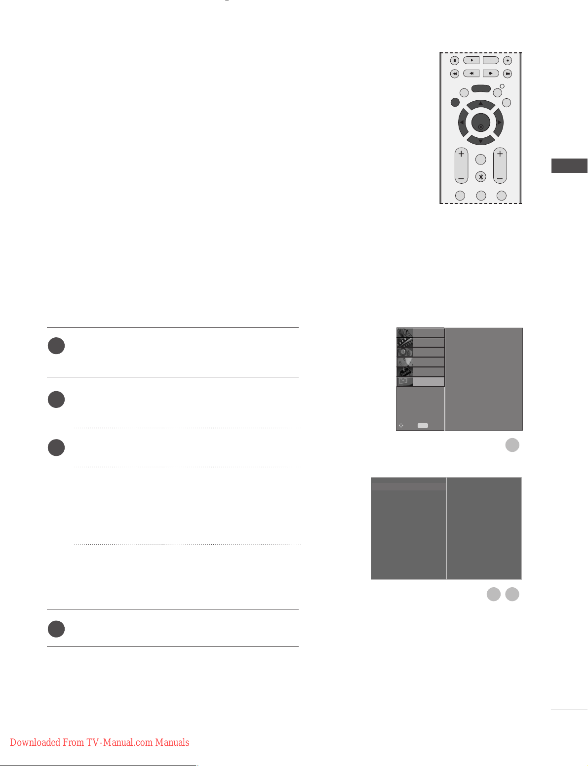
Screen Setup for PC mode
Automatically adjusts picture position and minimizes image
instability. After adjustment, if the image is still not correct, your
TV is functioning properly but needs further adjustment.
Auto configure
This function is for automatic adjustment of the screen position,
clock, and phase. The displayed image will be unstable for a few
seconds while the auto configuration is in progress.
Press the MENU button and then
D
or
E
button to
select the SCREEN menu.
Press the
G
button and then
D
or
E
button to select
Auto Config..
Press the
G
button to start Auto Config..
• When Auto Config. has finished, OK will be shown
on screen.
• If the position of the image is still not correct, try
Auto adjustment again.
• If picture needs to be adjusted again after Auto
adjustment in RGB (PC), you can adjust the
Manual Config..
Press the EXIT button to return to normal TV viewing.
Auto Configure (RGB [PC] mode only)
Auto Config. G
Manual Config.
XGA Mode
Aspect Ratio
Reset
To Set
1
3
2
1
2
3
4
Auto Config.
Manual Config.
XGA Mode
Aspect Ratio
Reset
SETUP
O
PICTURE
O
Prev.
MENU
Move
AUDIO
O
TIME
O
OPTION
O
SCREEN G
EXTERNAL EQUIPMENT SETUP
EXIT
BACK
MENU
OK
INFO i
GUIDE
VOL PR
123
FAV
MUTE
Downloaded From TV-Manual.com Manuals
28
EXTERNAL EQUIPMENT SETUP
EXTERNAL EQUIPMENT SETUP
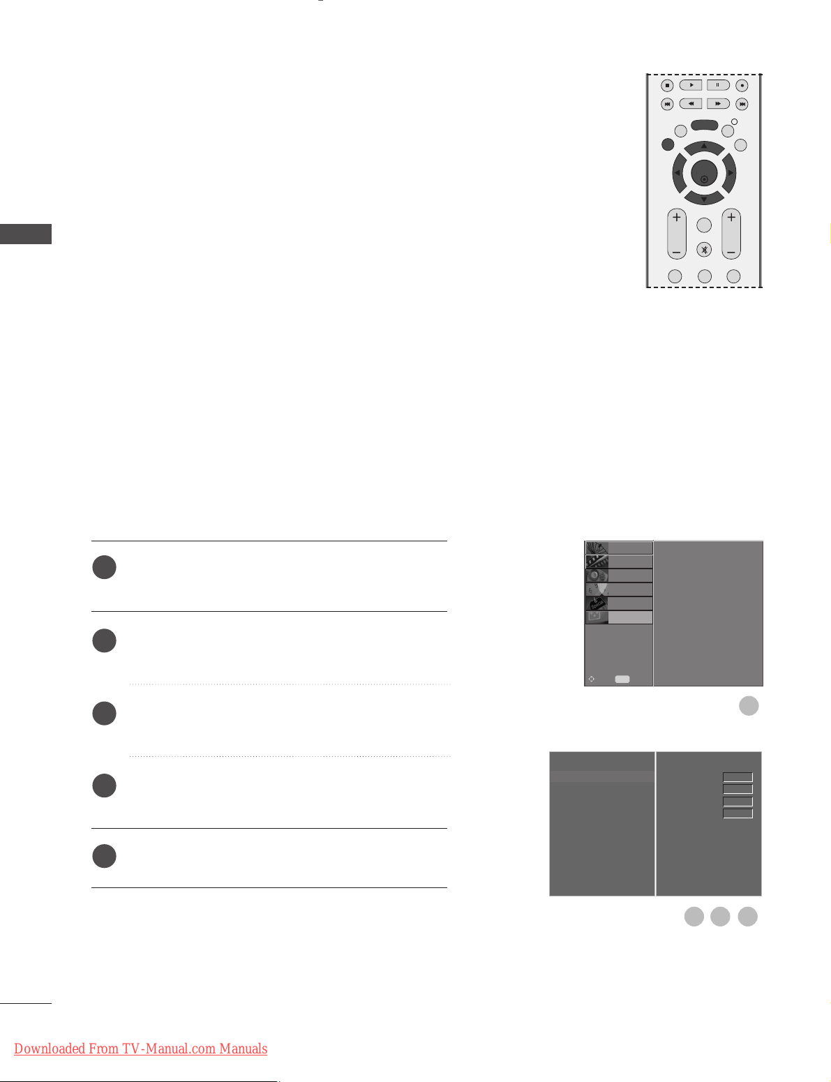
If the picture is not clear after auto adjustment and especially if
characters are still trembling, adjust the picture phase manually.
To correct the screen size, adjust Clock.
This function works in the following mode : RGB[PC].
Clock This function is to minimize any vertical bars or stripes
visible on the screen background the horizontal screen
size will also change.
Phase This function allows you to remove any horizontal noise
and clear or sharpen the image of characters.
Press the MENU button and then
D
or
E
button to
select the SCREEN menu.
Press the
G
button and then
D
or
E
button to select
Manual Config..
Press the
G
button and then
D
or
E
button to select
Phase, Clock, H-Position or V-Position.
Press the
F
or
G
button to make appropriate
adjustments.
Press the EXIT button to return to normal TV viewing.
Adjustment for screen Phase, Clock, Position
Auto Config.
Manual Config.
G
XGA Mode
Aspect Ratio
Reset
Phase
Clock
H-Position
V-Position
0
0
0
0
1
1
2
3
4
5
Auto Config.
Manual Config.
XGA Mode
Aspect Ratio
Reset
SETUP
O
PICTURE
O
Prev.
MENU
Move
AUDIO
O
TIME
O
OPTION
O
SCREEN G
3 4
2
OK
EXIT
VOL PR
GUIDE
BACK
MENU
123
MUTE
INFO i
FAV
Downloaded From TV-Manual.com Manuals
 Loading...