

Page 1

Setup & Operation Guide
for
Commercial Mode
Note: All features shown within this guide may not be
available on all models.
© Copyright 2008, LG Electronics U.S.A., Inc.
Integrated TVs
Experienced Installer
Master TV Setup
page 6
Cloning Information
pages 7-8-9
32LC50C
32LC50CB
32LC50CS
32LX50C
32LX50CS
37LC50DC
37LC50CB
42LB50C
42LC50C
Page 2
206-4071
PAGE 2
Installer Overview
This is the commercial mode setup guide only. For all other
information refer to the separately-supplied TV Owner’s Manual
(Users guide).
Operating Installer Menu
To set up the controls for the TV you will need to know how to enter
the TV Installer menu and make changes to the default values as
required. If necessary, familiarize yourself with the TV Installer menu
and how to make and save changes in the menu.
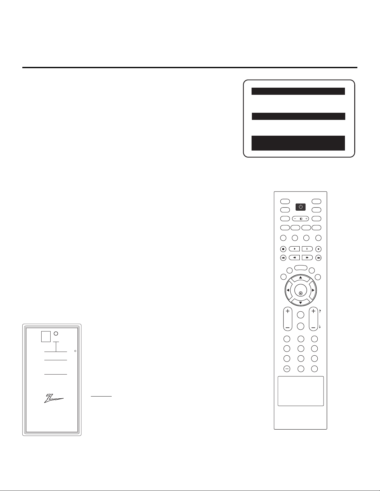
LG Installer Remote
You will need an LG Installer remote control similar to the one
shown to the right. The installer remote must have a “Source” button or its equivalent. The remote shown in this manual has “INPUT”
-- this button serves the purpose of a Source button.
The TV’s clonable features need to be set up. This is a critical step.
If the Master TV display panel’s clonable features like adding channel
icons or channel labels are not done properly, then the cloned TV
TVs will all have problems. Refer to the Owner’s Manual for other TV
features: Video, Audio etc.
LT2002 Clone Programmer
As the cloning procedure is being performed, specific steps need to
be done at the indicated times to achieve the desired result. Be sure
to do each cloning task as indicated. If a procedure or step is left
out or not performed correctly, then the TV
setup will be wrong and cloning may not
work. At each step, pay attention to assure
the TV screen shows the proper message(s)
when cloning. If the message indicated does
not appear, there is a problem with that step
and cloning may not be successful. Cloning is
only possible when the signal source is an
An
alog channel, not a digital channel.
Typical Installer Menu
PTC INSTALLER MENU
000 INSTALLER SEQ 000
Connect cable to
TV MPI Jack and
follow on screen
instructions
Status
Indicator
MPI
Color
• green battery ok
• red battery low
Blink pattern
• slow power on
no communications
• heartbeat power on
communications ok
Reset
®
QuickSet II Programmer
LT2002
UPN 000-000-000-000 FPGA E0F1
PTC V1.00.000 CPU V3.06.00
INPUT MODE
POWER
INPUT
MULTI
PIP CH - PIP CH +
PIP
EZ PIC
EZ SOUND
CC
EXIT
VOL
123
456
789
SWAP
MENU
ENTER
TIMER
MUTE
0
PIP INPUT
RATIO
CH
FLASH
BACK
TVTV
DVD
VCR
INFO
SAP
PAGE
ZENITH ELECTRONICS CORPORATION, LINCOLNSHIRE, ILLINOIS, USA
Page 3

PAGE 3
Use this page as a reference to find pages or sections to go to and set up the TV features.
Go to page 6 to begin the Commercial Mode Master TV setup.
1. Connect TV to RF signal source.
2. Customize TV features and set up other operational controls in the Installer’s menu.
3. Copy the Master TV setup into the clone programmer.
4. Transfer the Master TV setup from the clone programmer to identical TVs.
Installer Overview . . . . . . . . . . . . . . . . . . . . . . . . . . . . 2
Table of Contents . . . . . . . . . . . . . . . . . . . . . . . . . . . . 3
Typical Installer’s Remote Control . . . . . . . . . . . . . . . . . . 4
Remote Key Functions . . . . . . . . . . . . . . . . . . . . . . . . . 5
Commercial Mode Setup . . . . . . . . . . . . . . . . . . . . . . . 6
Master TV Cloning Connections and Cloning Overview . . . . . 7
Cloning Learning Setup . . . . . . . . . . . . . . . . . . . . . . . . . 8
Cloning Connections/ Teaching Setup . . . . . . . . . . . . . . . 9
Installer’s Menus . . . . . . . . . . . . 10 - 11 - 12 - 13 - 14 - 15
References
Clonable Menu Features Chart . . . . . . . . . . . . . . . . . . . . 16
Editing Channel Icons/Adding Ch Labels 2-5-4 + Menu Mode 17
Detailed Instructions For Making A Master TV . . . . . . . . . 18
Software Updating Procedure . . . . . . . . . . . . . . . . . . . 19
Camport Auto Sense Operation . . . . . . . . . . . . . . . . . . . 20
Aux Input Configuration . . . . . . . . . . . . . . . . . . . . . . . 21
Troubleshooting . . . . . . . . . . . . . . . . . . . . . . . . . 21 - 22
Cloning Troubleshooting . . . . . . . . . . . . . . . . . . . . . . . 23
Troubleshooting Flow Chart . . . . . . . . . . . . . . . . . . . . . 24
Commercial Mode Check . . . . . . . . . . . . . . . . . . . . . . . . 25
RJP Mode Configuration . . . . . . . . . . . . . . . . . . . . . . . 26
Glossary of Terms . . . . . . . . . . . . . . . . . . . . . . . . . . . . 27
Back Cover . . . . . . . . . . . . . . . . . . . . . . . . . . . . . . . . 28
Notes
• See the Installer’s menus to set up the operational features of the TV. The Installer’s section content is intended to be used primarily by qualified electronics technicians.
• Reference is made to installer remote controls used for menu operation within the manual. The remote information is provided for
reference only. The typical installer remote control shown for reference in this manual may be different than the actual remote
control supplied with the TV.
• For any additional information, contact your LG representative.
Note: Design and specifications are subject to change without prior notice.
Marketed and Distributed in the United States by LG Electronics U.S.A., Inc.
1000 Sylvan Avenue
Englewood Cliffs, NJ 07632
206-4071
Table of Contents
For Customer Support/Service please call:
1-888-865-3026
www.lgcommercial.com
Page 4
206-4071
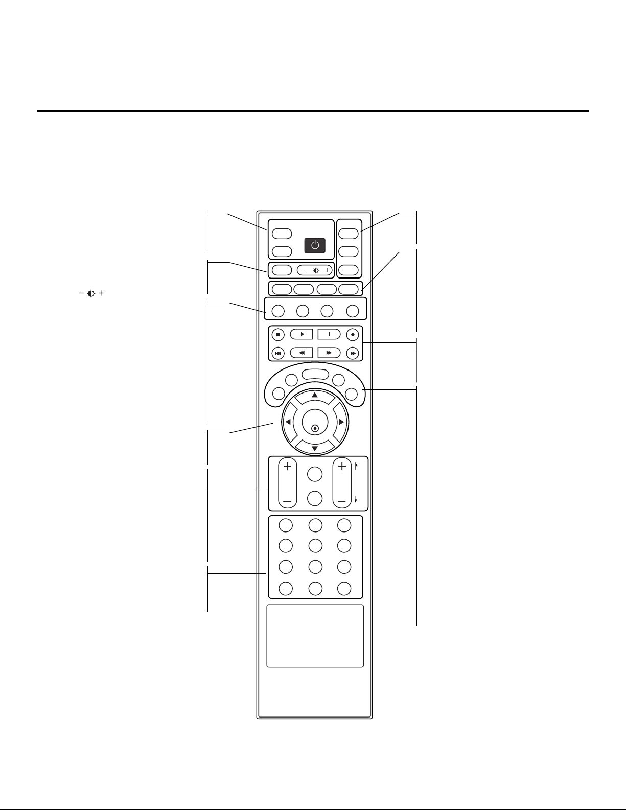
Typical Installer Multi-Brand Remote Control
LG Multi-brand Remote Control
Use the MODE button to select TV and put installer remote into TV
operating mode.
Notes: This remote is supplied with the TV. This typical LG multi-brand
remote control is shown for reference.
See next page for typical key functions in TV mode.
Follow the instructions provided on page 10 to access the Installer
menus.
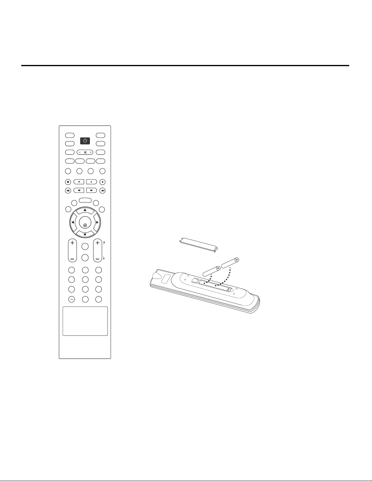
Installing Batteries in Installer Remote Control
• Remove the battery compartment cover on the back side by
pressing the arrow tab forward and lifting. Install batteries
matching correct polarity as shown (+ with + and - with -).
• Install two high-quality alkaline 1.5V AA batteries. Never mix
old or used batteries with new ones. Replace cover.
PAGE 4
INPUT MODE
POWER
INPUT
MULTI
PIP CH - PIP CH +
PIP
EZ PIC
EZ SOUND
CC
EXIT
VOL
123
456
789
SWAP
MENU
ENTER
TIMER
MUTE
0
PIP INPUT
RATIO
CH
FLASH
BACK
DVD
VCR
TVTV
SAP
INFO
PAGE
AA +
AA +
Page 5
TV INPUT/INPUT
Select available input sources.
POWER
Turns your TV or any other programmed
equipment On or Off, depending on mode.
MULTI
Selects RGB, HDMI,DVI, HDMI2 and Component
Input sources.
Adjusts picture brightness.
EZ PIC
Selects the factory preset picture appropriate
for the viewing environment.
EZ SOUND
Sets the appropriate sound for the program’s
content.
SWAP
Exchanges the main/sub images in
Twin picture mode.
INFO
While watching a TV program, will display
program information on top of the screen. Info
feature is not functional for Aux sources.
THUMBSTICK
Up/Down/Left/Right/ENTER
Use to navigate on-screen menus / adjust the
system settings to your requirements.
VOLUME UP/DOWN
Increases/decreases the sound level.
TIMER
Sets the amount of time before the TV
automatically turns itself Off.
MUTE
Switches the sound on or off.
CHANNEL UP/DOWN/PAGE
Selects available channels found with EZ Scan.
Moves to next available page.
NUMBER Buttons (0 - 9) DASH
Use to enter a program number or channels.
Dash for multiple channels such as 9-1, 9-2, etc.
FLASHBK
Returns to the previously viewed channel.
MODE
Selects remote operating mode: TV, VCR, or DVD.
Select these other operating modes, for remote
to operate external devices.
PIP
Turns Twin Picture mode on and off.
Switches video window lock/unlock in the
Listings Grid.
PIPCH- / PIPCH+
In twin picture mode, tunes to next lower/higher
channel.
PIP INPUT
Selects input source for the sub picture.
VCR/DVD BUTTONS
Control some video cassette recorders or DVD
players. (“RECORD” is not functional in DVD
mode.) Set up for VCR recording: Once, Regularly,
Weekly, Off. (“RECORD” button only).
EXIT
Clears all on-screen displays and returns
to TV viewing from any TV menu.
CC
Selects a closed caption option:
Off, CC1 ~ 4, Text1 ~ 4.
MENU
Brings up the main menu to the screen.
Enters or exits a Panel Menu in the TV Guide
on-screen menu system.
RATIO
Adjusts the picture aspect ratio.
SAP
Selects MTS sound:
Mono, Stereo, and SAP in Analog mode.
Changes the audio language in DTV mode.
SAP Notes
• SAP settings are retained with power off/on
for individual analog channels.
• If SAP is selected and no SAP is provided,
sound will not be heard on channel.
• Each analog channel may have its own SAP
setting.
• Digital channels will reset to default audio language with a power off/on.
ENTER
TVTV
INPUT
INPUT MODE
DVD
MULTI
EXIT
VOL
EZ SOUND
INFO
SWAP
EZ PIC
TIMER
MUTE
CH
SAP
CC
RATIO
MENU
VCR
POWER
123
456
789
0
FLASH
BACK
PIP
PIP CH - PIP CH +
PIP INPUT
PAGE
Remote Control Key Functions. To put remote into TV operating mode, select TV with the MODE key.
Notes: This remote is supplied with the TV. This typical LG multi-brand remote control is shown for reference.
Follow the instructions provided on the next page to access the Installer menus.
Installer Remote Control Typical Key Functions
PAGE 5
206-4071-C
Page 6

206-4071
PAGE 6
Commercial Mode Setup for Master TV
This page provides an overview of the TV configuration. See the pages listed below for more
specific, detailed instructions at each step; how to access and use the Installer menu etc.
Note 1: Disconnect all Aux inputs. Under certain conditions, EZ Scan (Channel
search) is disabled if there is an Aux input active.
Overview: Commercial Mode Setup Procedure
1. Set Installer Menu Items
(Enter Installer Menu, see page 10 for detailed instructions.)
a. Set Installer menu item 117 FACT DEFAULT, to 001 and press ENTER.
(This clears all installer menu items, custom settings, channel
labels/icons and reloads the factory default settings.)
b. Set Item 003 BAND/AFC.
- Broadcast: set to 000.- HRC: set to 002
- CATV: set to 001. - IRC: set to 003
c. Set item 028 CH OVERIDE to 001. This allows access to EZ Scan, Manual
Scan and Channel Edit options in the Setup Menu.
d. Set other particular installer items that affect your TV programming net-
work. See pages 10 - 15.
e. After all required installer menu item settings have been adjusted, press
ENTER on the remote to remove Installer Menu.
2. Set Up TV Features (See TV Owners Manual)
(Audio, Lock, Time menus etc. See TV Clonable options list on page 16.)
3. Run EZ Scan
(Search for all available channels.) Go to the Setup menu and access the
EZ Scan option, follow onscreen instructions.
a. Edit Channel Scan. In the Setup Menu, access the Channel Edit menu.
• Add/Delete channels manual scan menu per your system requirements.
Note: Physical channel numbers are used to indicate Virtual channels.
• Add familiar Channel Icons like ABC, CBS, NBC etc. to the channel
onscreen display. Add identifiable labels for the end user to readily know
what common networks are available. In the Setup menu, select the
Channel Label option, follow instructions on the bottom of the screen.
4. Transfer TV Setup to Controller Box: 2-5-5 + Menu
After the TV channel scan has been edited and channel label icons added,
enter the Installer menu. Once in the Installer menu, press 2-5-5 and MENU
on the remote. This transfers the TV setup to the internal controller box.
5. Perform Adding Custom Channel Labels: 2-5-4 + Menu Mode
Enter Installer menu, press 2-5-4 and Menu. Add your own custom labels to
channel onscreen displays. (See page 17.) To remove menu press MENU.
Verify TV Setup
At this point, verify that the channel lineup, channel icons and custom
labels are correct. Make sure the TV features are set per your requirements.
Set item 028 Ch Overide to 000 to lock the channel scan. After the preceding has been completed, the Master TV setup is ready to be copied to
the LT2002 Clone Programmer, see next page.
TV Installer Menu
Set these Installer Menu Items
Custom Channel Label ‘WXYZ’ created in
2-5-4 + Menu Add Channel Label Mode
After TV setup has been verified,
set item 028 Ch Overide back to 000.
PTC INSTALLER MENU
000 INSTALLER SEQ 000
UPN 000-000-000-000 FPGA E0F1
PTC V1.00.000 CPU V3.06.00
117 FACT DEFAULT 00X
003 BAND/AFC 00X
028 CH. OVERIDE 001
DIGITAL 19-3
STEREO SAP
MONO
WXYZ
028 CH. OVERIDE 000
Page 7
Before you begin cloning...
• The Master TV should be connected to a good, stable signal
from an over-the-air antenna or cable service Analog channel
and connected to power. (See above.)
• Teaching and Learning is only possible between identical
model devices. (However, the LT2002 Clone programmer can
store up to 3 different ‘master’ setups.)
WARNING: Copying a blank or incorrect memory into a TV, STB
or other device will cause the TV, STB or other device to
operate erratically or become inoperable.
• Use an Installer’s remote to operate Learning and Teaching
menus.
• Make sure that the batteries in the Clone programmer are
fresh.
• If batteries are removed, the Clone Clock time will be lost.
• Decide if you want to set the time from the Clone programmer or copy the time to the Clone programmer; from a compatible TV which has the clock set to the current time.
• Setting the time and transferring it to the Clone or other
device is a separate procedure.
• Follow the connection diagram above to connect the Clone to
a Master TV TV display panel. After learning is complete, to
another identical TV TV display panel to “teach” it the master
setup.
• See the Clone Troubleshooting section to resolve problems.
Tur n to the next page to continue Cloning Setup.
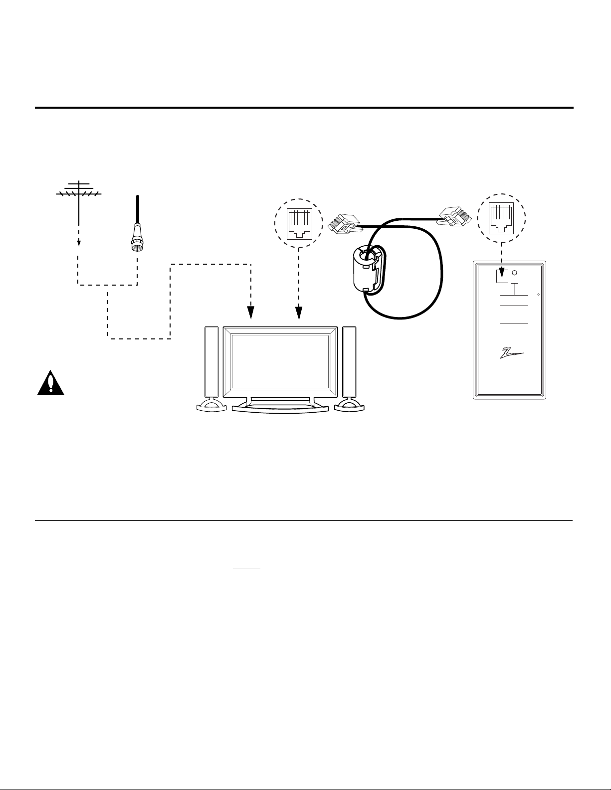
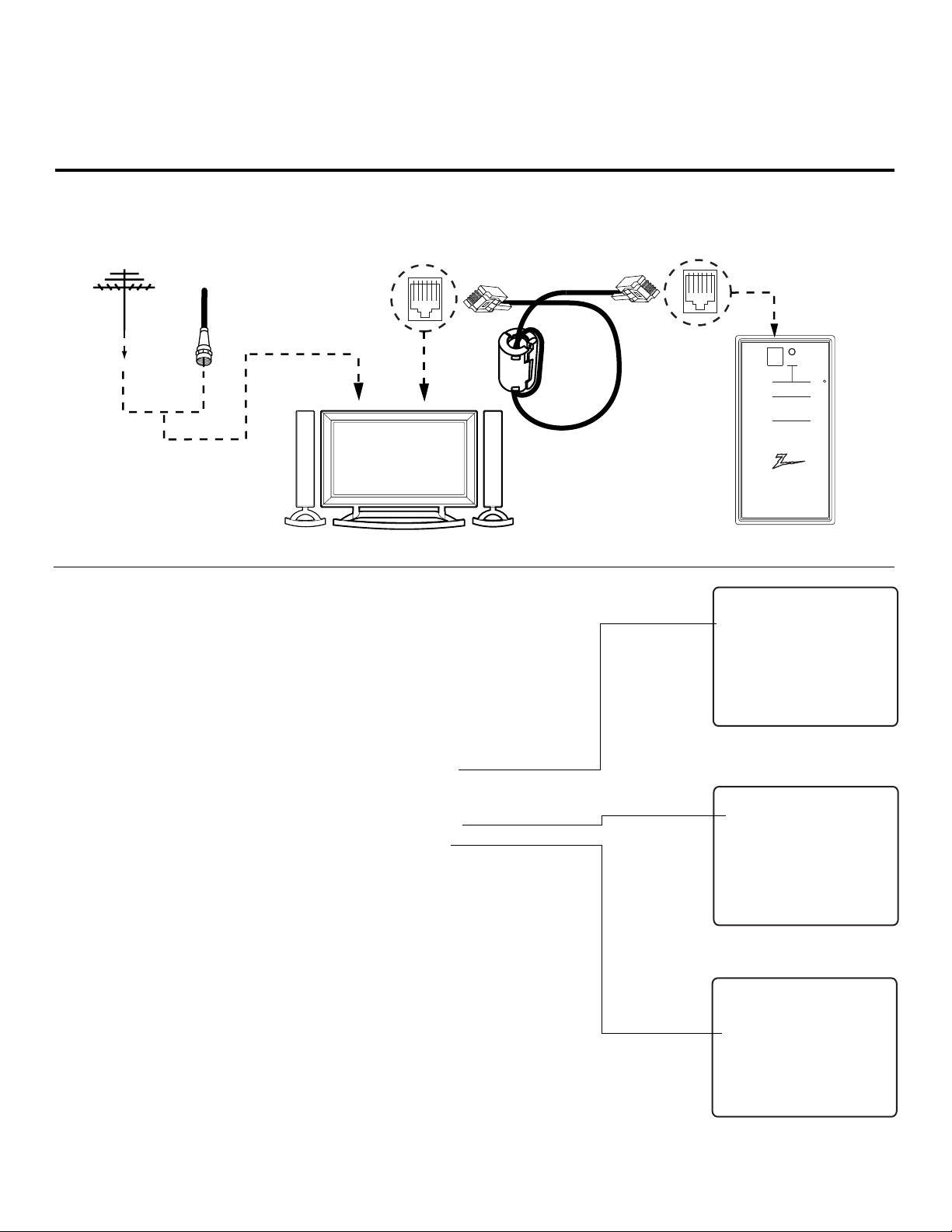
Connections for the LT2002 Clone Programmer to Learn the TV Master TV Setup
Notes: It is assumed that the TV is connected to a signal source, the source selected is Antenna (RF) In, the
signal is from an Analog channel, not a digital channel, all equipment is connected to power and turned on
and the LT2002 Clone Programmer main menu (THE CLONE HAS CONTROL OF THE TV) menu is displayed on the
TV screen, see above and next page.
Cloning Connections/Learning Setup
PAGE 7
206-4071
Warning: Do not use
LT2002 while any PPV
card is installed in TV or
clone programmer device
will be damaged.
Antenna
or CATV
Ferrite Core
(TDK, ZCAT
2035-0930)
Connect cable to
TV MPI Jack and
follow on screen
instructions
Status
Indicator
MPI
Color
• green battery ok
• red battery low
Blink pattern
• slow po wer on
no communications
• heartbeat power on
communications ok
Reset
THE CLONE HAS CONTROL OF THE TV
THE CLONE IS VERSION XX
THE TV IS VERSION XX
THE SW IS REVISION XX
CLONE CLOCK = XX:XX
TV CLOCK = XX:XX
-PRESS ANY KEY TO CONTINUE.
-DISCONNECT CLONE WHEN DONE.
QuickSet II Programmer
®
LT2002
ZENITH ELECTRONICS CORPORATION, LINCOLNSHIRE, ILLINOIS USA
Master TV
Clone Programmer
Page 8

Use MPI Cable to Connect LT2002 Clone Programmer to
Master TV MPI Port
If there is a good connection, “THE CLONE HAS CONTROL OF TV”
message will appear. Press any key on the Installer remote.
Learn Setup from Master TV
Press 1 to select the “LEARN FROM TV” option, then press ON/OFF,
POWER, or ENTER to go to the Memory Bank Selection Menu. Pick the
Memory ”Bank” you want to store the master TV’s setup in by pressing either Channel key repeatedly to choose Memory 1, 2 or 3. (If
you choose a Memory “Bank” that has a master device’s setup programmed into it, that setup will be overwritten by the new master
TV’s setup.) Once the Clone memory bank is selected, press ON/OFF,
POWER, or ENTER. The Clone memory bank you have selected will be
shown. Press ON/OFF or POWER to begin copying the master TV’s
setup.
Set the Clock (Optional)
Set the time on a Master TV’s Clock. (If the time has already been
copied from a TV into the Clone programmer, you can set a master
TV’s clock by copying the time from the Clone programmer.) The
Clone Programmer can copy the current time to both a master TV and
to the Clone’s internal clock; accurate to within one minute. (Another
reason that the Clone programmer should be equipped with fresh,
high-quality alkaline batteries, is for it to keep the time as accurately as possible.)
Since the Clone Programmer’s time cannot be set directly, the current
time needs to be copied from a Zenith/LG TV equipped with M.P.I.
input capability.
After the time is copied to the Clone programmer, the current time
can then be transferred to another TV. (This can be a master TV, or
another TV which has already had the features set up.)
206-4071
PAGE 8
Instructions for the Clone Programmer to Learn the Master TV Setup
LT2002 Clone Programmer Communication Problems
• A slow flashing green light indicates there are communication problems between the TV and the LT2002 clone programmer. If this is the case, check for a damaged cable, poor contacts, or other connection troubles.
• If the status indicator is red, the programmer batteries are
low and should be replaced. Install 4 high-quality alkaline
AA batteries.
Learning the Master TV Setup
This menu should appear by itself after the
LT2002 is connected to the TV MPI port.
This menu should appear after any key is
pressed on the Installer remote.
Cloning Learning Setup
THE CLONE HAS CONTROL OF THE TV
THE CLONE IS VERSION XX
THE TV IS VERSION XX
THE SW IS REVISION XX
CLONE CLOCK= XX:XX
TV CLOCK= XX:XX
-PRESS ANY KEY TO CONTINUE.
-DISCONNECT CLONE WHEN DONE.
CLONE SELECTION MENU
(1) LEARN FROM TV
(2) TEACH TO TV
(3) SET CLONE CLOCK FROM TV
(4) SET TV CLOCK FROM CLONE
(5) DISPLAY TV SETUP
(6) DISPLAY CLONE SETUP
-TO CHANGE MENU ITEMS, PRESS
CHANNEL KEYS OR DIGITS.
-TO EXECUTE ITEM, PRESS ON/OFF,
POWER, OR ENTER
Page 9
PAGE 9
206-4071
Teach Master TV’s Setup to
the target TV
After learning is complete, remove the M.P.I. cable from the
master TV and connect it to the target TV that you want to
copy the master TV’s setup into. With “THE CLONE HAS
CONTROL OF TV” message displayed, press 2 or use either
Channel key to go to the “TEACH TO TV” option, press ON/OFF,
POWER, or ENTER. Select the LT2002 memory that the new
setup is in. Press On/Off to transfer the new setup and other
information to the new TV. Teaching usually takes 2-3 minutes.
After the “TEACHING COMPLETE” message is displayed, press
any key to return to the Clone menu, then press ON/OFF,
POWER, or ENTER. If finished, detach M.P.I. cable from the
target, newly-cloned TV.
Disconnect TV Power for 15 Seconds
Unplug the AC power cord of the newly-cloned TV from the
power outlet for about 15 seconds to activate the newlycopied setup.
This display will appear after Teaching
is complete.
This display will appear during
Teaching function.
Teaching the Master Setup to Another TV
Connections for the LT2002 to Teach another TV the Master Setup
This menu should appear after any key
is pressed on the Installer remote.
Cloning Connections/Teaching Setup
Antenna
or CATV
THE CLONE HAS CONTROL OF THE TV
THE CLONE IS VERSION XX
THE TV IS VERSION XX
THE SW IS REVISION XX
CLONE CLOCK = XX:XX
TV CLOCK = XX:XX
-PRESS ANY KEY TO CONTINUE.
-DISCONNECT CLONE WHEN DONE.
Target TV
Ferrite Core
(TDK, ZCAT
2035-0930)
Connect cable to
TV MPI Jack and
Status
follow on screen
Indicator
instructions
MPI
Reset
Color
• green battery ok
• red battery low
Blink pattern
• slow power on
no communications
• heartbeat power on
communications ok
®
QuickSet II Programmer
LT2002
ZENITH ELECTRONICS CORPORATION, LINCOLNSHIRE, ILLINOIS USA
Clone Programmer
CLONE SELECTION MENU
(1) LEARN FROM TV
(2) TEACH TO TV
(3) SET CLONE CLOCK FROM TV
(4) SET TV CLOCK FROM CLONE
(5) DISPLAY TV SETUP
(6) DISPLAY CLONE SETUP
-TO CHANGE MENU ITEMS, PRESS
CHANNEL KEYS OR DIGITS.
-TO EXECUTE ITEM, PRESS ON/OFF,
POWER, OR ENTER
TEACHING IN PROGRESS,
PLEASE WAIT
TEACHING COMPLETE
Page 10

Use the Installer’s Menu to set up or change operational settings.
See more detailed descriptions of the Installer menu items on the following pages...
Accessing the Installer’s Menu
Make sure TV is on. Installer’s menu items can be accessed by using an installer’s remote
control. Just press MENU repeatedly until the TV seems to stop responding, then press 9,
8, 7, 6, then ENTER to access the Installer’s menu. To remove the Installer’s menu, press
ENTER again. Any changes you make will be stored in nonvolatile memory. (The menu also
disappears automatically.)
The Installer’s menu opens with item 000 INSTALLER SEQ 000. Use the Up/Down arrow
keys to sequence through the available menu items. Or, access an item directly by keying
in the line number, then pressing MENU. For example, to access the Sleep Timer option
which is item 015, press 0-1-5, then MENU. To change a setting, use the Left/Right
arrow keys. Or, enter a value directly.
Using the Installer’s Menu
Items 000 ~ 117 are immediately accessible only upon entering the Installer’s Menu.
Their numbers, descriptions, ranges, factory default settings, and a place for listing any
changes made on-site are given below and on the following pages.
Installer Menu Items 000 through 117
Typical Installer Menu
Menu Item Function Value Range Default Value Brief Description of Function and Comments
000 INSTALLER SEQ 0 ~ 3 0 Leave default set to 0.
001 POWER MANAGE 0 ~ 7 0 Sets number of hours of no activity before auto shut Off.
002 AC ON 0 / 1 0 Set to 1 to enable auto turn On at power up.
003 BAND/AFC 0 ~ 3 1 Selects Tuning Band: 0=Broadcast, 1=CATV, 2=HRC, 3=IRC
004 STRT CHANNEL 0~125, 126, 127, 255 255 Channel at turn-on (Set 255 to return to last channel before power Off).
005 CHAN LOCK 0 / 1 0 If set to 1, cannot tune from current channel.
007 STRT VOLUME 0 ~ 63, 255 255 Sets Volume level at TV turn-on (Set 255 to retain last volume level).
008 MIN VOLUME 0 ~ 63 0 Sets minimum allowable volume setting.
009 MAX VOLUME 0 ~ 63 63 Sets maximum allowable volume setting.
010 MUTE DISABLE 0 / 1 0 Set to 1 to disable mute function.
011 KEY DEFEAT 0 / 1 0 Set to 1 to disable menu navigation keys on display panel.
015 SLEEP TIMER 0 / 1 1 Set to 1 to enable Sleep Timer.
016 EN TIMER 0 / 1 0 Set to 1 to enable On/Off Timers.
017 ALARM 0 / 1 1 Set to 1 to enable Alarm.
021 V-CHIP 0 / 1 1 Set to 1 to enable V-Chip functions.
022 MAX BLK HRS 0 ~ 99 12 Sets number of V-Chip (Parental Control) blocking hours.
023 CAPTION LOCK 0 / 1 0 Set to 1 to retain caption setting at power Off.
028 CH. OVERIDE 0 / 1 1 If set to 0, limits direct access to favorite channels.
029 OLD OCV 0 / 1 0 Set to 1 to change M.P.I. operation to OCV.
030 ACK MASK 0 / 1 0 If set to 1, changes M.P.I. for some OCV boxes.
031 POLL RATE 20 ~ 169 94 Selects poll rate for M.P.I.
032 TIMING PULSE 186 ~ 227 207 Sets baud rate for M.P.I.
034 CAMPORT EN 0 / 1 1 Set to 1 to enable Video 2 input.
Installer Menu
206-4071
PAGE 10
PTC INSTALLER MENU
000 INSTALLER SEQ 000
UPN 000-000-000-000 FPGA E0F1
PTC V1.00.000 CPU V3.06.00
Page 11

Menu Item Function Value Range Default Value Brief Description of Function and Comments
035 COMPPORT EN. 0 / 2 1 Set to 0 to disable HDMI 1. Set to 1 for DTV, set to 2 for PC.
038 YPrPb EN. 0 / 1 1 Set to 1 to enable display panel Component Video input jacks.
039 REAR AUX EN 0 / 1 1 Set to 1 to enable display panel Video 1 input jack.
040 AUTO CAMPORT 0 / 1 1 Set to 1 to automatically switch to Camport.
046 STRT AUX SRCE Note 1 255 Sets the starting AUX source.
047 AUX STATUS 0 / 1 0 Set to 1 for M.P.I. AUX source to be reported as a channel number instead of Channel 0.
053 DIS. CH-TIME M. 0 / 1 0 Set to 1 to disable Channel-Time display.
069 EN. CH-T COL. 0 / 1 1 Set to 1 to enable custom color for the Channel-Time display.
070 FOR. CH-TIME 0 ~ 7 2 Chooses custom foreground color for the Channel-Time display.
071 BCK. CH-TIME 0 ~ 7 2 Chooses custom background color for the Channel-Time display.
073 CH NOT AVBLE 0 / 1 0 If set to 1 and channel override is 0, “NOT AVAILABLE” message is displayed
when directly accessing a channel not in the TV memory channel list.
075 REVERT CH 0 / 1 0 If set to 1 and loss of M.P.I. communication occurs, TV tunes to Start Channel.
078 UPN MSB 0 ~ 255 0 User programmable number, most significant byte.
079 UPN MSB-1 0 ~ 255 0 User programmable number, most significant byte - 1.
080 UPN MSB-2 0 ~ 255 0 User programmable number, most significant byte - 2.
081 UPN LSB 0 ~ 255 0 User programmable number, least significant byte.
082 CHKSM ERROR 0 / 1 1 Enforces rigid M.P.I. checksum.
083 HANDSHK TIME 0 ~ 5 5 Relaxes M.P.I. timing to be compatible with PC based Windows-controlled systems.
084 PERMANENT BLK 0 / 1 0 Removes block hours setting for Parental Control and makes block permanent.
087 REAR RGB EN. 0, 1, 2, 2 Set to 0 to disable RGB1. Set to 1 to enable for RGB DTV mode. Set to 2 to enable for RGB PC.
17, 18 Set to 17 for one time auto configuration in DTV mode.
Set to 18 for one time auto configuration in PC mode.
088 EN NOISE MUTE 0 / 1 1 If set to 1, mutes audio if no signal is present.
090 KEY LOCK 0 / 1 0 If set to 1, keyboard is locked out, IR is still functional.
091 YPrPb2 EN. 0 / 2 1 Set to 0 to disable HDMI 2. Set to 1 for DTV, set to 2 for PC.
093 RJP AVAILABLE 0, 1, 2, 5, 6 0 Set to 0 to disable. Set to 1, 2, 5 or 6 for HDMI or DVI mode. (See detailed descriptions)
094 SAP MENU EN 0 / 1 1 Set to 0 to disable feature on Function menu. Set to 1 to enable feature on Function menu.
096 DEF. ASP. RATIO 0 ~ 5 2 Sets default aspect ratio at power up. See detailed descriptions and item 106.
099 BACK LIGHTING 1 ~ 100 100 Sets the power saving mode by controlling the brightness of the picture.
101 ~ 200
102 ATSC BAND 0 ~ 4 4 Selects ATSC band.
103 ATSC TUNE MODE 0 / 1 1 Default 01 for physical channel scan. Set to 0 for Virtual Channel scan.
104 START MINOR CH 0 ~ 255 0 Selects Minor start channel. Set 0 for NTSC. Not 0, sets Minor channel number.
106 ASP RATIO LOCK 0 / 1 0 To retain set aspect ratio on power cycle, set to 1. Set to 0 for default ratio on power cycle.
116 VIDEO MUTE EN 0 / 1 0 Set to 0 for normal, set to 1 for Blank.
117 FACT DEFAULT 0 / 1 0 0=Normal. 1=Loads presets of all above settings.
Installer Menu Items 035 through 118
Installer Menu
PAGE 11
206-4071
Note 1: Dependent on item 093 RJP Available setting.
Page 12

PAGE 12
Detailed Descriptions of Installer Menu Items
000 - INSTALLER SEQUENCE
Specifies entry sequence to the Installer Menu.
0 = 9876 1 = 4321
2 = 1478 3 = 3698
001 - POWER MANAGE (Power Management)
Determines hours of no activity before automatic shutoff. The POWER
MANAGE function is for saving energy. If set to 0, Power Manage is Off.
Settings range from 0 ~ 7, with 1 ~ 7 representing the hours that the
unit will remain On, unless there has been activity from either the
control panel or remote control.
002 - AC ON (AC Power Switchable)
If set to 1, allows the TV to turn On just by applying AC power.
Pressing the On button is not necessary. This is desirable if the TV is
plugged into a cable box or a power outlet controlled by a wall switch.
Use ADJ Left/Right arrow to choose 0 or 1 where 0 is the default is
Off, and 1 is On.
NOTE: If set to 1 (On), the TV does not respond to On/Off commands
from either the remote or the display control panel, and the SLEEP
TIMER is also nonfunctional.
003 - BAND/AFC (Band/Automatic Frequency Control)
There are 4 possible settings for this option:
0 = Broadcast 1 = CATV
2 = HRC 3 = IRC
If some channels were not found by EZ SCAN (Auto Program), select
the appropriate Band setting here and add the channels using the
Channel Edit option in the Setup Menu.
004 - STRT CHANNEL (Start Channel)
If active, this function allows you to determine the initial channel
number when the TV is turned On. This feature is useful for an inhouse information channel, since the TV would always select that
channel when it is turned On. Setting this to 255 causes the last
channel viewed when the TV was turned Off, to be the tuned to channel when the TV is turned On again. Note: For a digital Start Channel,
always remember to set item 104 to the Minor Start Channel number.
255 = Last channel 1 ~ 125 = Ch X 0 = Aux
126 Map to Channel 3. 127 Map to Channel 4.
005 - CHAN LOCK (Channel Lock)
CHAN LOCK is ideal if the system must always be on the same channel.
Changing channels with Channel Up/Down or keypad numbers is impossible. Channel Lock is inactive if set to 0 (default).
Generally, this feature is used in connection with START CHANNEL
(Installer item 004) where the start channel may, for example, be set
to 3 or 4. If the start channel is 3, then the TV will remain locked on
Channel 3.
NOTE: For Items 007, 008 and 009
For legacy reasons, the scale used is 0 - 63. The PTC software will
translate this to the 0 - 100 scale used by the TV.
To translate a TV volume level to the installer menu value, use the following formula:
Installer Value = TV V
alue x 63
100
Enter only the whole number (disregard fractions).
007 - STRT VOLUME (Start Volume)
This function allows the Installer to determine the initial volume level
setting when the TV is turned On. This feature is useful for an in-house
information channel, since the TV would always select that volume
level when it is turned On. The range of values are 0 - 63, 255. If 255
is selected, the current volume level will be retained in memory when
the TV is turned Off; at turn On, the volume level will be automatically
set at the previous or last level.
008 - MIN VOLUME (Minimum Volume)
This function determines the minimum volume level allowable with the
VOLUME (VOL) Up/Down control. In this way, for example, someone
cannot set the volume too low to hear. The value range is from 0 to 63
— change values with ADJ Left/Right arrow. The factory default is 0,
which provides the full range of volume control, if item 009 MAX VOLUME is also set to 63. It may be best to set the same value on every
TV.
NOTE: The minimum volume level cannot have a value setting higher
than the MAX VOLUME level (described below).
009 - MAX VOLUME (Maximum Volume)
This function determines the maximum volume level allowable with the
VOLUME (VOL) Up/Down controls. In this way, for example, someone
can not set the volume level high enough to disturb others. The value
range is 0 to 63, with 63 as the default, which gives the user the full
range of volume control, if item 008 MIN VOLUME is also set at 0.
Change values with ADJ Left/Right arrow keys. It may be best to set
the same value on every TV.
NOTE: The maximum volume level cannot have a value setting lower
than the MIN VOLUME level (described previously).
010 - MUTE DISABLE
Enables or disables sound mute function. If set to 1, sound cannot be
muted. If set to 0, sound can be muted.
206-4071
Installer Menu
Page 13

PAGE 13
206-4071-D
011 - KEY DEFEAT (Keyboard Defeat)
If set to 1, key defeat prevents the end user from accessing the onscreen menus with the display front panel—MENU, SELECT, and Left /
Right arrow keys do not function. If set to 0, those keys do function.
NOTE: The menus can always be accessed by pressing MENU on the
remote.
015 - SLEEP TIMER
If set to 1, the SLEEP TIMER feature may be used. If set to 0, the
Sleep Timer is not available.
016 - EN TIMER (Enable On/Off Timers) *
If set to 1, Timer function is available to user and enabled continuously. Set to 0 to disable On/Off Timers. (Clock must be set in order to
use Timers.)
017 - ALARM *
Gives the installer the option of making the Alarm function available
to the end user. If set to 1, Alarm function is available to end user.
Set to 0 to disable the Alarm function.
NOTE: Clock must be set before the Alarm function will work.
021 - V-CHIP (Parental Control) *
Set to 1 to activate V-Chip (Parental Control); have it available to end
user to filter and control or otherwise restrict programming content
that can appear. Set to 0 to turn V-Chip feature Off, not available to
user; no programming restrictions can be set.
022 - MAX BLK HRS (Maximum Block Hours) *
Sets hours from 0 to 99 for the maximum V-Chip (Parental Control)
block hours. Default setting is for 12 blocking hours.
023 - CAPTION LOCK
Set to 1 to restore previous caption On/Off state after turn Off. If set
to 0, captions are always Off at turn On.
028 - CH. OVERIDE (Channel Override)
If set to 1, the user can select channels with either Channel up/down
or by direct keypad entry. If set to 0, only those channels that are
entered for scanning can be selected.
029 - OLD OCV (On Command Video
TM
)
Set to 1 for operation with systems from On Command Corporation.
030 - ACK MASK
M.P.I. Communication Parameter. Leave at default setting unless
changed by Pay-Per-View provider. When set to 1, changes M.P.I. for
some OCV boxes.
* Only affects Function Menu if enabled by some PPV providers.
031 - POLL RATE
M.P.I. Communication Parameter. Selects Poll Rate for M.P.I. Leave at
default setting unless changed by Pay-Per-View provider. Step size of
16 ms.
032 - TIMING PULSE
M.P.I. Communication Parameter. Leave at default setting unless
changed by Pay-Per-View provider. Sets baud rate. Step size of 4.3 uS.
034 - CAMPORT EN. (Camera Port Enable)
Set to 1 to enable Video 2 input on display panel. If set to 0, Video 2
input on display panel is not functional.
NOTE: S-Video overrides Video jack.
035 - COMPPORT EN. (Computer Port Enable)
Enable/disables display panel HDMI1 input jack. Set to 0 to disable,
set to 1 to enable DTV mode, set to 2 for PC mode.
NOTE: The setting above is ignored if Installer item 093 RJP AVAILABLE, is set to 1.
038 - YPrPb EN. (Rear Component Video Enable)
Set to 1 to enable display panel rear Component Video input jacks.
Set to 0 to disable display panel rear Component Video input jacks.
039 - REAR AUX EN. (Rear Aux Enable)
Set to 1 to enable display panel rear AUX (Video 1) input.
Set to 0 to disable display panel rear AUX (Video 1) input.
Note: S-Video overrides Video.
040 - AUTO CAMPORT
Set to 1 to automatically switch to Camport when equipment is connected to front Video input.
Set to 0 to disable front Video automatic source selection.
NOTE: If set to 1, 093 RJP Available is automatically set to 0.
046 - STRT AUX SRCE (Start Aux Source)
Sets the starting AUX source. At power up, TV will tune to starting Aux
source if item 004 Start Channel is set to 0.
If item 093 RJP Available is set to 0 and item
040 Auto Camport is set to 0:
1 = Video 1 4 = RGB 255 = Last Aux
2 = Video 2 5 = HDMI 2
3 = HDMI 1 6 = Component
If item 093 RJP Available is set at 1:
2 = Video 2 5 = HDMI 2 6 = Component
If item 040 Auto Camport is set to 1:
1 = Video 1 5 = HDMI 2
3 = HDMI 1 6 = Component
4 = RGB
Installer Menu
Page 14

PAGE 14
206-4071
Installer Menu
047 - AUX STATUS
Set to 1 for M.P.I. AUX source to be reported as a channel number
instead of channel 0. Set to 0 to disable AUX identification change.
Controls M.P.I. status channel response for AUX inputs.
053 - DIS. CH-TIME (Disable Channel-Time)
Set to 1 to disable the Channel-Time display, Channel-Time display will
not appear.
Set to 0 to enable the Channel-Time display.
069 - EN. CH-T COL. (Enable Channel-Time Custom Color)
Set to 1 to enable custom color for the Channel-Time display.
Set to 0 to disable custom color for the Channel-Time display.
070 - FOR. CH-TIME (Channel-Time Display Foreground Color)
Set according to Color Chart.
0 = Black 3 = Cyan 6 = Yellow
1 = Blue 4 = Red 7 = White
2 = Green 5 = Violet
NOTE: If foreground and background color are the same, menu background is transparent.
071 - BCK. CH-TIME (Channel-Time Display Background Color)
Set according to Color Chart.
0 = Black 3 = Cyan 6 = Yellow
1 = Blue 4 = Red 7 = White
2 = Green 5 = Violet
NOTE: If foreground and background color are the same, menu background is transparent.
073 - CH NOT AVBLE (Channel Not Available)
If set to 1 and item 028 CHANNEL OVERRIDE is set to 0, “NOT AVAILABLE” message is displayed when directly accessing a channel not in
the channel scan list available in memory.
075 - REVERT CH (Revert to Start Channel)
If set to 1 and loss of M.P.I. communication occurs, TV automatically
tunes to the specified Start Channel.
078 - UPN MSB (UPN Most Significant Byte)
User programmable number, most significant byte readable by M.P.I.
command. Note: Not linked to serial number.
079 - UPN MSB-1 (UPN Most Significant Byte-1)
User programmable number, most significant byte-1 readable by M.P.I.
command. Not linked to serial number.
080 - UPN MSB-2 (UPN Most Significant Byte-2)
User programmable number, most significant byte-2 readable by M.P.I.
command. Not linked to serial number.
081 - UPN LSB (UPN Least Significant Byte)
User programmable number, least significant byte readable by M.P.I.
command. Not linked to serial number.
082 - CHKSM ERROR (Checksum Error)
Enforces rigid M.P.I. checksum validation.
Set to 1 for validation.
Set to 0 to disable (does not check checksum on M.P.I. async port).
SPI is always checked.
083 - HANDSHK TIME (Handshake Time)
Adds an additional delay to the handshake time which is 64 msec,
thus relaxing M.P.I. timing requirements to be compatible with PC
based Windows controlled systems, range is 0 - 5.
(Timeout = 25.5MS + [25.5 MS* Handshake time]).
084 - PERMANENT BLK (Permanent Block)
Allows Lock (Parental Control) blocking schemes to be permanent by
disabling the blocking hours function.
Set to 1 to install Parental Control restrictions permanently.
Set to 0 for user-specified hours control of blocking schemes.
087 - REAR RGB EN. (Rear RGB Enable)
Controls access to rear RGB input on TV.
Set to 0 to disable RGB input.
Set to 1 to enable RGB in DTV mode.
Set to 2 to enable RGB in PC mode.
If set to 1 or 2, auto configuration is performed when RGB is selected
or input change is detected.
Set to 17 to enable RGB in DTV mode.
Set to 18 to enable RGB in PC mode.
If set to 17 or 18, auto configuration is done one time after a power
cycle.
088 - EN NOISE MUTE (Enable Noise Mute)
If set to 1, audio mutes if no signal is present.
090 - KEY LOCK
If set to 1, display panel keyboard is locked out, not available to end
user. IR receiver remains functional.
091 - YPrPb2 EN. (HDMI2 Enable)
Set to 0 to disable display panel HDMI2 input.
Set to 1 to enable DTV mode. Set to 2 to enable PC mode.
Detailed Descriptions of Installer Menu Items
Page 15

206-4071
PAGE 15
093 - RJP AVAILABLE (Remote Jack Pack Available)
0 = Remote jack pack is not available or disabled.
1 = Series 100 RJP, HDMI Mode
Enables RJP when an HDMI cable is inserted into RJP. Video is from
HDMI. Audio stream is expected from HDMI source. If no audio is present, no audio will be heard.
2 = Series 100 RJP, DVI Mode
Enables RJP when an HDMI cable is inserted into RJP. Video is from
HDMI however, Audio is from selected audio source, based on the RJP’s
audio hierarchical priority.
5 = Series 200 RJP, HDMI Mode
Enables RJP when an HDMI cable is inserted into RJP. VIdeo is from
HDMI. Audio stream is expected from HDMI source. If no audio is present, no audio will be heard.
6 = Series 200 RJP, DVI Mode
Enables RJP when an HDMI cable is inserted into RJP. Video is from
HDMI however, Audio is from selected audio source, based on the RJP’s
audio hierarchical priority.
Notes:
• See Reference section, RJP Mode Configuration page.
• If set to 1, 2, 5 or 6, item 040 Auto Camport is automatically
set to 0.
Settings 1, 2, 5 and 6 allow the lodge staff to customize each TV’s RJP
setup based on customer requirements.
094 - SAP MENU EN (2nd Audio Program)
Set to 1 to enable SAP feature on Function menu, if Function menu is
available.
Set to 0 to disable SAP feature on Function menu, if Function menu is
available.
096 - DEF. ASP. RATIO (Default Aspect Ratio)
Selects default aspect ratio at power up, see settings below.
Set to 0 “Set By System”.
Set to 1 for 4:3.
Set to 2 for 16:9 (Factory Default).
Set to 3 for Horizon
Set to 4 for Zoom 1
Set to 5 for Zoom 2
099 - BACK LIGHTING
Sets the TV screen brightness at power up, see settings below.
Default setting is 100 power saving mode is disabled.
1 - 100 Static Backlighting.
(1 = Dimmest picture, 100 = Brightest picture.)
101 - 200 Dynamic Backlighting.
(101 = Dimmest picture, 200 = Brightest picture.) TV automatically
controls backlighting depending upon the picture level of the current
program.
102 - ATSC BAND
Sets up TV to receive different types of incoming signals:
0=Broadcast, 1=CATV, 2=HRC, 3=IRC, 4=Same as NTSC.
103 - ATSC TUNE MODE
Sets ATSC tuning mode: Default set to 1 for Physical channel scan.
Set to 0 for Virtual Channel scan.
104 - START MINOR CHANNEL
Sets XX-XX minor starting channel at power up: 0=NTSC. If not 0, number selected is the Minor start channel number.
106 - ASP RATIO LOCK (Aspect Ratio Lock)
Set to 1 to retain previous aspect ratio with power Off.
Set to 0 to retain default aspect ratio with power Off. See item 96
Default Aspect Ratio above.
116 - VIDEO MUTE EN (Video Mute Enable)
Set to 0 for normal.
Set to 1 for blank.
117 - FACT DEFAULT (Factory Default)
Set to 0 for normal.
Set to 1 to load presets to all of the previous item settings.
WARNING: Setting this to 1 will reload the factory defaults
and clear the channel list including erasing any assigned
Channel Icons and Custom Channel Labels.
Installer Menu
Page 16

PAGE 16
206-4071
Reference: Clonable Menu Features
Note: Video Menu and other feature settings are not clonable on all TVs. End user has access to EZ
Picture, EZ Sound and Ratio on user remote control.
Menu /Sub Menu Features
Setup
SET ID
Audio
Audio Language
EZ SoundRite
EZ sound
Balance
Treble
Bass
Front Surround
TV Speaker
BBE
Time
Auto Clock
Auto Off
Clonable Menu Features
Option
Aspect Ratio
Caption
Caption Mode
DTV Captions Style - Style
DTV Captions Style - Size
DTV Captions Style - Font
DTV Captions Style - Text Color
DTV Captions Style - Text Opacity
DTV Captions Style - BG Color
DTV Captions Style - BG Opacity
DTV Captions Style - Edge Type
DTV Captions Style - Edge Color
Language
Cinema
ISM Method
Low Power
Lock
Movie Rating
TV Rating – Children Age
TV Rating – Children Fantasy
Violence
TV Rating – General Age
TV Rating – General Dialogue
TV Rating – General Language
TV Rating – General Sex
TV Rating – General Violence
Page 17

PAGE 17
206-4071-C
Changing a Channel’s ICON on
Master TV
1. With Channel Up/Down, select the
channel you want to change the
Icon for.
2. With the Right or Left ADJ arrow,
select the letter ‘I’ on the channel
ID display.
3. With the Up or Down arrow, select
the desired ICON you want to
appear to identify the channel. (If
you know the ICON number, enter
the number followed by Enter /
Select.)
4. Proceed with Changing/Adding
Labels or go to the next channel.
Changing/Adding Channel Labels
on Master TV
1. Channel Up/Down to select the desired
channel.
2. Press the Right or Left ADJ arrow
repeatedly until the numbers 1 to 7
show up. The number shows the position of the character that can be
changed. Number 1 is the first character, number 2 the second character
and so on.
3. With the Up or Down arrow, select the
desired character.
4. Proceed to the next number position
or use Channel Up/Down to go to the
next channel.
Changing Source Labels on
Master TV
1. Press “INPUT” to select the desired
Aux input source; Video 1, Component,
S-Video etc.
2. Press the Right or Left arrow repeatedly until the numbers 0 to 9 shows up.
The number shows the position of the
character that can be changed.
3. Use the Up or Down arrows to select
the desired character.
4. Press “INPUT” for the next Aux source
or proceed with Changing Icon or
Changing/Adding Labels.
• CHANNEL Up/Down - Tunes in the next channel in scan.
• Left/Right Arrows - Select the item to change. If “I” is
shown, the ICON can be changed. If a number is shown, it
indicates the position of the character that can be changed.
• Up/Down Arrows - Select the ICON or the character to be
displayed.
• 0 – 9 - Use to enter the index number of the ICON, if known.
• ENTER/SELECT - Changes the ICON after the number has
been entered.
• INPUT - Changes the Aux input label. (“Source” on the
remote shown in this manual is INPUT.)
• MENU - Exits the editing process.
Installer Remote Control Key Functions for Master TV Channel Editing/Labeling Menu
Adding Channel Icons and Labels in the 2-5-4 + Menu Mode
Reference: Procedures for adding Channel Label Icons/Custom Channel Labels
(2-5-4 + MENU Mode)
Editing/Adding Channel ICONs and/or Labels
If there is no pre-assigned ICON, you can make a custom channel label of up to 7 characters to help in identifying the channel or network. At your option, channel labels can also be
added in addition to a pre-assigned ICON. You may also add
labels for the Aux input sources to clearly identify the devices
that are connected to the Aux inputs.
Editing and adding the labels can only be done if there are
channels entered into the TV’s channel map either by using the
method described in item 6 (page 18), by cloning or by the use
of the master remote control from the PPV provider.
Note: A blank letter space is available between ‘Z’ and ‘!’.
To Do Channel Editing/Labeling, proceed
as follows
1. Enter TV Installer menu.
2. Once the installer menu appears, press ‘2’, ‘5’, ‘4’,
‘MENU’. This enters the channel label editing mode.
Add your channel icons and channel labels in this
menu, see below. (You can do this more than once.)
3. To exit the menu when done press “MENU”.
(Icon)
(Label)
XYZ
XYZ
XYZ
NETWORK
2
4
1
3
7
5
6
Page 18

206-4071
IMPORTANT INSTALLER SETUP INFORMATION! PLEASE READ THE FOLLOWING...
To set up a master TV you will need to know how to
enter the TV Installer menu and make changes to
the default values as required. If necessary, famil-
iarize yourself with the TV Installer menu and how
to make and save changes in the menu, before attempting to
clone the TV Master TV setup.
You will also need an LG Installer remote control similar to
the one shown in the front of this manual. The installer remote
must have a “Source” button or its equivalent. The remote
shown in this manual has a “INPUT” button -- this button
serves the purpose of a Source button.
Finally, the TV’s clonable features need to be set up. This is a
critical step. If the Master TV display panel’s clonable features
like adding channel icons or channel labels, digital font options
etc., are not correctly added, then the cloned TVs will all have
problems.
As the cloning procedure is being performed, specific steps
need to be done at the indicated times to achieve the desired
result. Be sure to do each task as indicated. If a procedure or
step is left out or not performed completely, cloning may not
work. At each step, pay attention to assure the TV screen shows
the proper message when cloning. If the message indicated
does not appear, there is a problem with that step and cloning
may not be successful. Cloning is only possible when the signal
source is an Analog channel, not a digital channel.
Reference: Detailed Information For Making A Master TV
Making a Master TV
Detailed Instructions
The following describes the procedure for preparing a Master TV
for cloning and the procedure for adding Channel Icons and/or
Labels.
Note 1: Disconnect all Aux inputs. Under certain conditions, EZ
Channel Scan is disabled if there is an Aux input active.
Note 2: Under certain conditions, changes to the input mode of
the RGB inputs will not take effect until the power is cycled (TV
is turned Off and On). To avoid confusion, disconnect all RGB
inputs before entering the Installer menu.
1. Enter the TV installer menu.
a. Reset the internal controller to factory default by accessing installer menu item 117 FACT DEFAULT, set it to 1 and
press “ENTER”. The value will change back to 0 after the TV’s
internal controller has been restored to factory default condition. This step will ensure that the TV channel memory will
be the active channel list. Check the Status LED. If it is
blinking rapidly then the TV channel map is in use.
b. Within the Installer menu, set the Installer menu items to
the configuration required of your institution.
c. It is important to set the tuning band at this time, see
Installer menu item 03 BAND/AFC.
d. Set Installer menu item 28 – CH OVERIDE to 001 to allow
access to the EZ Channel Scan and Surf List/Ch. Edit features
in the SETUP Menu. Exit the Installer menu.
2. Access the Master TV menus and set the clonable options on
the menus to the desired configuration. Refer to the
Clonable Menu Features Chart on page 16 in this manual.
3. Run EZ Channel Scan to find analog and digital channels.
4. Enter the Channel Edit menu and edit the channel lineup to
include the Free-To-Guest Channels only.
5. Assign ICONs to the channels using the Channel Label Menu.
Note: You can add Channel ICONS typically network logos
like ABC, NBC, PBS etc. in this step. Or, in Step 7, add
Channel ICONS or labels for channels without Icons.
6. Transfer the TV setup: Enter the TV installer menu. Press ‘2’,
‘5’, ‘5’, ‘MENU’ to start the transfer of the TV’s setup to the
TV. Once the transfer is complete, the system will exit the
Installer menu. Check the Status LED inside the TV. It should
be blinking slowly (1 blink per second).
7. Edit/Add Channel ICONs and Channel Labels as needed.
Enter Installer menu. With menu displayed, press 2-5-4 +
MENU. See page 17 for detailed instructions:
- Editing/Adding Channel ICON and Labels on Master TV
- Changing a Channel’s ICON on Master TV
- Changing/Adding Channel Labels on Master TV
- Changing Source Labels on Master TV
8. Verify Master TV setup and feature configuration:
• Did you add Channel ICONS?
• Did you add Channel Labels?
• Did you add Source Labels?
• Did you adjust all TV menu options as required?
After verifying master setup, enter the TV Installer menu and
set Installer menu item 28 CH OVERIDE to 000. Press ENTER
to remove and exit the Installer menu.
PAGE 18
Page 19

PAGE 19
206-4071
Procedure for Checking Software Version
The software version of the TV may be checked by accessing the INSTALLER MENU. To do this, press the MENU button
repeatedly until the menu display ceases to respond to MENU key presses.
Then, press "9", "8", "7", "6", "ENTER/SELECT".
Typical Installer Menu
Reference: Checking Software Version
PTC INSTALLER MENU
000 INSTALLER SEQ 000
UPN 000-000-000-000 FPGA E0F1
PTC V1.00.000 CPU V3.06.00
Page 20

PAGE 20
206-4071
TV Camport Auto Sense Operation
The CAMPORT Auto Sense function is enabled when:
1. Installer Menu Item 34, CAMPORT EN is set to 1 AND
2. Installer Menu Item 40, AUTO CAMPORT is enabled (1).
Selectable= Can be accessed with INPUT key, direct access, etc.
Auto Sense= Switches to this input when connector is inserted.
The camport (Front Video) has the highest priority and will
override any commands including tuning to the Start Channel.
CAMPORT (Front Video) Functionality Control
Item 34 Item 40 Front Video
CAMPORT EN AUTO CAMPORT Operation
0 0 Disabled
0 1 Disabled
1 0 Selectable
1 1 Auto Sense
CAMPORT Operation (Stand-Alone)
When Camport Auto Sense is enabled as above, the TV’s source
will switch to the front video whenever a plug is inserted into
any of the front panel video inputs (either composite Video or
S-Video).
When the plug is removed, the TV will switch back to the previous channel or input source that the TV was using before the
plug was inserted. However, if any direct access to an RF channel or Aux channel is requested while the camport is active,
then, when the camport plug is removed, the TV will switch to
the last requested channel. Source changes using any Source
Keys (INPUT) are ignored. Channel Up/Channel Down and
Flashback Commands are not direct access tuning commands
and they are also ignored.
Previous State Operation State
Before Inserting While CAMPORT Upon Removal
CAMPORT Is Active Of CAMPORT
Aux or RF Channel None Previous Aux
or RF Channel
Aux or RF Channel Direct Access Last Requested
RF or Aux Channel
Aux or RF Channel Ch Up/Down, Previous Aux
Flashback or RF Channel
and TV/AV Keys
CAMPORT Operation (PPV)
The operation will be similar to that of the Stand-Alone mode.
However, the PPV providers may send different commands to
the TV for the same user commands. For instance, some
providers will always send a direct tune command when it
receives a channel up/down or a flashback command while
other PPV providers will just send a key command.
Previous State Operation State
Before Inserting While CAMPORT Upon Removal
CAMPORT Is Active Of CAMPORT
Aux or RF Channel None Previous Aux
or RF Channel
Aux or RF Channel Direct Access Last Requested RF
or Aux Channel
Aux or RF Channel Ch Up/Down, Last Requested
Flashback Channel if PPV
and TV/AV Keys translates it to
direct access tuning
command. Otherwise,
goes to Previous Aux
or RF Channel
Page 21

206-4071
PAGE 21
TV Aux Input Configuration / Troubleshooting
Troubleshooting
Some quick and easy tips to resolving problems
Symptoms Possible Cause(s) Possible Solution(s) See Page(s)
Software Problems
Cannot direct enter Channel not included in channel After 2-5-5 + MENU, only channels included in TV controller will appear. 6
channel number or scan in TV controller. If channel is available it can be added to channel scan. If it is not
“No Signal” appears. available, the ‘No Signal’ message appears on the TV screen.
Page 22

PAGE 22
206-4071
Some quick and easy tips to resolving problems
Symptoms Possible Cause(s) Possible Solution(s) See Page(s)
Power
No Power. See troubleshooting flow chart. 24
Display Panel Picture
No Picture. • Display panel is turned off. -Turn TV on.
-Power failure?
• Antenna/Cable not connected. -Connect Antenna/Cable signal to TV. (See Owners manual)
• Connections incorrect. -Check connections on TV. (See Owners manual)
• M.P.I. not connected. -If applicable, connect M.P.I. cable to M.P.I. device.
• Encrypted program. -Try another channel.
• Wrong tuning band. -Adjust Installer menu settings. 10 ~ 15
Erratic Operation
Installer menu setup. • Wrong Installer menu settings. -Adjust Installer menu settings as required. 10 ~ 15
Remote Control
Remote doesn’t work. • Remote not in TV mode. -Use Mode key to select TV; puts remote into TV mode. 5
• Not aimed at IR remote sensor. -Point remote at TV’s IR receiver on TV.
• Remote too far from IR sensor. -Move remote closer to TV’s IR receiver or darken room.
• IR path to TV’s receiver obstructed. -Remove obstructions.
• Weak batteries. -Replace batteries. 4
• Wrong battery polarity. -Check that “+” and “-” match in battery compartment. 5
• Too much light in room. -Dim room light.
• Wrong Installer remote control. -Requires compatible Installer remote, contact your LG dealer. 2
Picture Reception
Normal picture, poor • Audio muted. -Press MUTE or use Volume Up key to increase sound level. 5
or no sound. • Broadcast problem. -Try a different channel. 5
Note: For other problems not caused by the TV, refer to other devices’ operating guide.
Troubleshooting
Page 23

PAGE 23
206-4071
Reset Clone After Static Shock
After replacing exhausted batteries, or if the programmer
behaves strangely after a static shock, use a paper clip or similar instrument inserted through the small hole marked ”RESET”
to activate the internal reset switch and restore normal operation. After a reset, check the real-time clock setting. It may be
necessary to reset the Clone Programmer clock from a TV containing the correct time.
Note
The LT2002 programmer is designed to be used with TVs containing the 221-01006 and later processors. Use with earlier TV
sets may give unpredictable results. Processors used before the
221-01006-04 have a limited screen display capability. They
cannot display entire screens as shown in the quick setup
instructions accompanying the LT2002 clone programmer. Use
the printed menu illustrations on the quick setup sheet supplied with the Clone as an aid to making your programming
choices. (Although the menus are not all displayed, the clone
functions all operate normally.)
• After cloning operations are complete, just unplug the LT2002 from the TV.
• If the TV does not display a picture on the TV (blank screen) after a few seconds, just change channels.
Clone Programmer Troubleshooting
Problem Possible Cause(s) Possible Solution(s)
Clone Programmer
Clone copies Setup in • Not enough time to copy - Press Reset on clone programmer, redo teach/learn.
less than 30 seconds entire TV setup. (Teach/Learn should take a minimum of 1 minute.)
Remote does not • Wrong Installer remote. - Only use an LG Installer remote to operate clone programmer
operate clone. with TV.
LED does not blink. • M.P.I. cord not connected. - Connect M.P.I. cord properly, assure good connection.
• TV not turned on. - TV must be powered On for clone to work.
• Weak batteries. - Install 4 fresh AA high-quality alkaline batteries.
Clone menu hard • Weak signal. - Connect TV to a reliable Analog channel signal
to read. source.
No time set. • Time not available. - Set time on a TV, copy time to Clone Programmer.
Clone not working. • Clone programmer - Try a different LT2002 Clone programmer.
problem. - Reset Clone Programmer.
Clone Scans Channels • Clone should only scan - Retry cloning again.
more than once. channels once.
Master and Other TVs
Cloning did not work. • Procedure interrupted. - Wait until procedure complete message is displayed.
• Different TV models. - Cloning is only possible with identical model TVs.
• Step(s) omitted or - Reread pages 7-8-9 to be sure all tasks were performed.
not performed.
Clone time disappeared. • Batteries were removed. - Batteries must remain installed to retain time settings.
New Setup not present. • TV not reset. - Disconnect newly-cloned unit from power for 5 seconds.
Reference: Cloning Procedure Troubleshooting
Warning: Do not use LT2002 while any PPV card is
installed in TV or clone programmer will be damaged.
Page 24

PAGE 24
206-4071
Troubleshooting Flow Chart
Controller
Quick
Check
Is
'STATUS'
LED on
Analog Board
Blinking
?
Is
Red LED
on TV
Lit
?
Yes
Cycle the power by removing
and re-connecting the AC
power cord. Observe the
'POWER' LED and TV screen
as soon as AC power is
re-applied.
No
Yes
No
Is
TV
Connected to
AC Power
?
Bad
TV
1. Bad Analog Board.
2. Bad Digital Board.
No
Yes
Plug
into AC
Power Outlet
Press 'POWER' or 'ON/OFF'
key on TV
Did
TV Turn
On
?
Press 'POWER' or 'ON/OFF'
or 'VOLUME UP/DOWN' or
'MUTE' key on Installer
Remote
Did
TV
Respond
?
No
Yes
No
Yes
1. Bad TV
1. Bad TV
2. Go to Remote
Control Checklist page 5
Board 'POWER'
LED Turn On
Momentarily
Momentarily
Did
Analog
?
Did TV
Turn On
?
Yes
Yes
No
No
Bad
TV
Check to see if TV
is in Commercial Mode.
See Commercial Mode
Check chart.
Press 'POWER' or 'ON/OFF'
or 'VOLUME UP/DOWN'
or 'MUTE' key on
User-Supplied Remote
Did
TV
Respond
?
End
No
Yes
1. Bad PPV Card
2. Go to Remote
Control Checklist page 5
Page 25

PAGE 25
206-4071
Commercial Mode Check
Press the "On/Off" key
on the front panel.
The On/Off key is always operational.
Did
you get
a response
?
Leave
the
TV set On
No
Yes
Go to Installer menu
by pressing "MENU" until
the TV stops responding.
Did
TV stop
responding
or continue
to respond
?
Continued
to
respond
TV is not in Commercial Mode
Call Technical Support for
Assistance
responding
Bad TV
Stopped
TV is in
Commercial
Mode.
Page 26

206-4071
Reference: RJP Mode Configuration
PAGE 26
Page 27

PAGE 27
206-4071
75 OHM RF CABLE
The wire that comes from an off-air antenna
or cable service provider. The end looks like
a hex-shaped nut with a wire sticking
through the middle. It screws onto the
Antenna/Cable threaded jack on the back of
the TV.
300 TO 75 OHM ADAPTER
A small device that connects a twowire 300 ohm antenna to a 75 ohm RF jack.
They are usually about an inch long with two
screws on one end and a round opening with
a wire sticking out on the other end.
ANALOG TELEVISION
Standard television broadcasting format in
4:3 picture aspect ratio.
A/V CABLES
Audio/Video cables. Three cables bunched
together—right audio (red), left audio
(white), and video (yellow). A/V cables are
used for stereo playback of videocassettes
and for higher quality picture and sound
from other A/V devices.
A/V DEVICE
Any device that produces video or sound
(VCR, DVD, cable box, or television).
AMPLIFIER
An electronic device that amplifies sound
from a television, CD player, VCR, DVD, or
other Audio/Video device.
ANTENNA
The physical receiver of television signals
sent over the air. A large metal piece of
equipment does not always have to be visible
to be using an antenna.
CABLE
Cable service box. Refers to the descrambler
box cable subscribers use to receive cable
programming signals.
CATV
Programming provided by a cable service.
DIGITAL TELEVISION
High-resolution, cinema-quality television
signals transmitted digitally.
DVI
Digital Video Interface
Accommodates analog and digital interfaces
with a single connector.
COMPOSITE VIDEO
Typical video jack, uses one wire for transporting three-color video signals.
COMPONENT VIDEO
Uses three wires for transporting three-color
video signals. The end result is usually better
video quality.
DELETED
Lets you remove channels from the list that
the end user can scroll through using CH
(Channel) Up/Down.
HDMI
High-definition multi-media interface.
HDTV
High-definition television. Refers to television signals that have higher resolution than
ordinary analog TV signals.
HDSTB
High-definition set top box. Refers to a
tuner device that receives high-definition
television signals which have higher resolution than ordinary analog TV signals.
INPUT
Refers to the input jack that receives a signal from a TV, VCR, DVD Player or other
Audio/Video device.
JACK
An input or output connector on the back
of a TV, VCR, DVD Player or other
Audio/Video device.
MONO SOUND
Mono (monaural) sound is one channel of
sound. On more than one speaker, all the
speakers play the same audio.
OUTPUT
Refers to the output jack that sends a signal
out of a VCR, DVD, or other A/V device.
PHYSICAL CHANNEL NUMBER
See Note 1.
RGB (Red, Green, Blue)
Connection input or output port available for
producing a video image using three separate colors: Red, Green, and Blue.
RS-232
Serial communication port through which
the display panel is controlled.
2ND AUDIO PROGRAMMING/SAP
Second Audio Programming (SAP) is another,
separate audio channel available with some
programming. Choosing SAP often refers to
listening to audio in another language, such
as Spanish or French.
SIGNAL
Picture and sound traveling through a cable,
or over the air, to the TV.
STEREO SOUND
Stereo (Stereophonic) sound refers to audio
that’s divided into right and left sides.
TUNER
Device that picks up the broadcast signal
and turns it into picture and sound.
VIRTUAL CHANNEL NUMBER
See Note 1.
XDS
Extended Data Service: Additional program
information included on the signal provided
at the discretion of the broadcaster.
Note 1
Refer to www.atsc.org for further information.
Glossary of Terms
A list of definitions for some of the words found in this guide
Page 28

For Customer Support/Service Please call:
1-888-865-3026
www.lgcommercial.com
© Copyright 2008, LG Electronics U.S.A., Inc.
206-4100
Issue*
Marketed and Distributed in the United States by LG Electronics U.S.A., Inc.
1000 Sylvan Avenue
Englewood Cliffs, NJ 07632
 Loading...