

Page 1

LCD TV
SERVICE MANUAL
CAUTION
BEFORE SERVICING THE CHASSIS,
READ THE SAFETY PRECAUTIONS IN THIS MANUAL.
CHASSIS : LA64A
MODEL : 37LC50CB
37LC50CB-UA
North/Latin America http://aic.lgservice.com
Europe/Africa http://eic.lgservice.com
Asia/Oceania http://biz.lgservice.com
Internal Use Only
Page 2

- 2 -
LGE Internal Use OnlyCopyright © 2008 LG Electronics. Inc. All right reserved.
Only for training and service purposes
CONTENTS
CONTENTS .............................................................................................. 2
PRODUCT SAFETY ..................................................................................3
SPECIFICATION ........................................................................................6
ADJUSTMENT INSTRUCTION ...............................................................12
TROUBLE SHOOTING ............................................................................18
BLOCK DIAGRAM...................................................................................24
EXPLODED VIEW .................................................................................. 25
REPLACEMENT PARTS LIST ............................................................... 27
SVC. SHEET ...............................................................................................
Page 3
LGE Internal Use OnlyCopyright © 2008 LG Electronics. Inc. All right reserved.
Only for training and service purposes
- 3 -
SAFETY PRECAUTIONS
IMPORTANT SAFETY NOTICE
Many electrical and mechanical parts in this chassis have special safety-related characteristics. These parts are identified by in the
Schematic Diagram and Exploded View.
It is essential that these special safety parts should be replaced with the same components as recommended in this manual to prevent
Shock, Fire, or other Hazards.
Do not modify the original design without permission of manufacturer.
General Guidance
An isolation Transformer should always be used during the
servicing of a receiver whose chassis is not isolated from the AC
power line. Use a transformer of adequate power rating as this
protects the technician from accidents resulting in personal injury
from electrical shocks.
It will also protect the receiver and it's components from being
damaged by accidental shorts of the circuitry that may be
inadvertently introduced during the service operation.
If any fuse (or Fusible Resistor) in this TV receiver is blown,
replace it with the specified.
When replacing a high wattage resistor (Oxide Metal Film Resistor,
over 1W), keep the resistor 10mm away from PCB.
Keep wires away from high voltage or high temperature parts.
Before returning the receiver to the customer,
always perform an AC leakage current check on the exposed
metallic parts of the cabinet, such as antennas, terminals, etc., to
be sure the set is safe to operate without damage of electrical
shock.
Leakage Current Cold Check(Antenna Cold Check)
With the instrument AC plug removed from AC source, connect an
electrical jumper across the two AC plug prongs. Place the AC
switch in the on position, connect one lead of ohm-meter to the AC
plug prongs tied together and touch other ohm-meter lead in turn to
each exposed metallic parts such as antenna terminals, phone
jacks, etc.
If the exposed metallic part has a return path to the chassis, the
measured resistance should be between 1MΩ and 5.2MΩ.
When the exposed metal has no return path to the chassis the
reading must be infinite.
An other abnormality exists that must be corrected before the
receiver is returned to the customer.
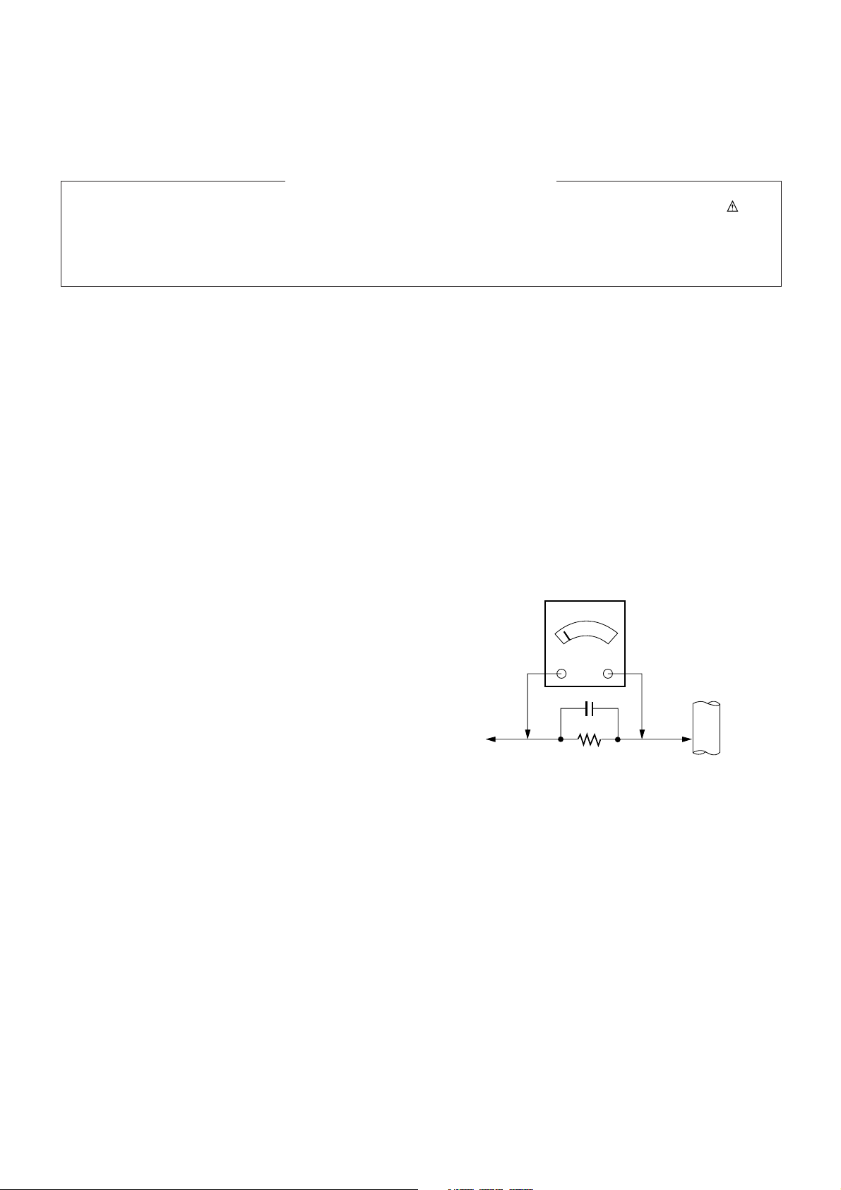
Leakage Current Hot Check (See below Figure)
Plug the AC cord directly into the AC outlet.
Do not use a line Isolation Transformer during this check.
Connect 1.5K/10watt resistor in parallel with a 0.15uF capacitor
between a known good earth ground (Water Pipe, Conduit, etc.)
and the exposed metallic parts.
Measure the AC voltage across the resistor using AC voltmeter
with 1000 ohms/volt or more sensitivity.
Reverse plug the AC cord into the AC outlet and repeat AC voltage
measurements for each exposed metallic part. Any voltage
measured must not exceed 0.75 volt RMS which is corresponds to
0.5mA.
In case any measurement is out of the limits specified, there is
possibility of shock hazard and the set must be checked and
repaired before it is returned to the customer.
Leakage Current Hot Check circuit
AC Volt-meter
Good Earth Ground
such as WATER PIPE,
To Instrument's
exposed
METALLIC PARTS
0.15uF
CONDUIT etc.
1.5 Kohm/10W
Page 4

LGE Internal Use OnlyCopyright © 2008 LG Electronics. Inc. All right reserved.
Only for training and service purposes
- 4 -
CAUTION: Before servicing receivers covered by this service
manual and its supplements and addenda, read and follow the
SAFETY PRECAUTIONS on page 3 of this publication.
NOTE: If unforeseen circumstances create conflict between the
following servicing precautions and any of the safety precautions on
page 3 of this publication, always follow the safety precautions.
Remember: Safety First.
General Servicing Precautions
1. Always unplug the receiver AC power cord from the AC power
source before;
a. Removing or reinstalling any component, circuit board
module or any other receiver assembly.
b. Disconnecting or reconnecting any receiver electrical plug or
other electrical connection.
c. Connecting a test substitute in parallel with an electrolytic
capacitor in the receiver.
CAUTION: A wrong part substitution or incorrect polarity
installation of electrolytic capacitors may result in an
explosion hazard.
2. Test high voltage only by measuring it with an appropriate high
voltage meter or other voltage measuring device (DVM,
FETVOM, etc) equipped with a suitable high voltage probe.
Do not test high voltage by "drawing an arc".
3. Do not spray chemicals on or near this receiver or any of its
assemblies.
4. Unless specified otherwise in this service manual, clean
electrical contacts only by applying the following mixture to the
contacts with a pipe cleaner, cotton-tipped stick or comparable
non-abrasive applicator; 10% (by volume) Acetone and 90% (by
volume) isopropyl alcohol (90%-99% strength)
CAUTION: This is a flammable mixture.
Unless specified otherwise in this service manual, lubrication of
contacts in not required.
5. Do not defeat any plug/socket B+ voltage interlocks with which
receivers covered by this service manual might be equipped.
6. Do not apply AC power to this instrument and/or any of its
electrical assemblies unless all solid-state device heat sinks are
correctly installed.
7. Always connect the test receiver ground lead to the receiver
chassis ground before connecting the test receiver positive
lead.
Always remove the test receiver ground lead last.
8. Use with this receiver only the test fixtures specified in this
service manual.
CAUTION: Do not connect the test fixture ground strap to any
heat sink in this receiver.
Electrostatically Sensitive (ES) Devices
Some semiconductor (solid-state) devices can be damaged easily
by static electricity. Such components commonly are called
Electrostatically Sensitive (ES) Devices. Examples of typical ES
devices are integrated circuits and some field-effect transistors and
semiconductor "chip" components. The following techniques
should be used to help reduce the incidence of component
damage caused by static by static electricity.
1. Immediately before handling any semiconductor component or
semiconductor-equipped assembly, drain off any electrostatic
charge on your body by touching a known earth ground.
Alternatively, obtain and wear a commercially available
discharging wrist strap device, which should be removed to
prevent potential shock reasons prior to applying power to the
unit under test.
2. After removing an electrical assembly equipped with ES
devices, place the assembly on a conductive surface such as
aluminum foil, to prevent electrostatic charge buildup or
exposure of the assembly.
3. Use only a grounded-tip soldering iron to solder or unsolder ES
devices.
4. Use only an anti-static type solder removal device. Some solder
removal devices not classified as "anti-static" can generate
electrical charges sufficient to damage ES devices.
5. Do not use freon-propelled chemicals. These can generate
electrical charges sufficient to damage ES devices.
6. Do not remove a replacement ES device from its protective
package until immediately before you are ready to install it.
(Most replacement ES devices are packaged with leads
electrically shorted together by conductive foam, aluminum foil
or comparable conductive material).
7. Immediately before removing the protective material from the
leads of a replacement ES device, touch the protective material
to the chassis or circuit assembly into which the device will be
installed.
CAUTION: Be sure no power is applied to the chassis or circuit,
and observe all other safety precautions.
8. Minimize bodily motions when handling unpackaged
replacement ES devices. (Otherwise harmless motion such as
the brushing together of your clothes fabric or the lifting of your
foot from a carpeted floor can generate static electricity
sufficient to damage an ES device.)
General Soldering Guidelines
1. Use a grounded-tip, low-wattage soldering iron and appropriate
tip size and shape that will maintain tip temperature within the
range or 500ºF to 600ºF.
2. Use an appropriate gauge of RMA resin-core solder composed
of 60 parts tin/40 parts lead.
3. Keep the soldering iron tip clean and well tinned.
4. Thoroughly clean the surfaces to be soldered. Use a mall wirebristle (0.5 inch, or 1.25cm) brush with a metal handle.
Do not use freon-propelled spray-on cleaners.
5. Use the following unsoldering technique
a. Allow the soldering iron tip to reach normal temperature.
(500ºF to 600ºF)
b. Heat the component lead until the solder melts.
c. Quickly draw the melted solder with an anti-static, suction-
type solder removal device or with solder braid.
CAUTION: Work quickly to avoid overheating the
circuitboard printed foil.
6. Use the following soldering technique.
a. Allow the soldering iron tip to reach a normal temperature
(500ºF to 600ºF)
b. First, hold the soldering iron tip and solder the strand against
the component lead until the solder melts.
c. Quickly move the soldering iron tip to the junction of the
component lead and the printed circuit foil, and hold it there
only until the solder flows onto and around both the
component lead and the foil.
CAUTION: Work quickly to avoid overheating the circuit
board printed foil.
d. Closely inspect the solder area and remove any excess or
splashed solder with a small wire-bristle brush.
SERVICING PRECAUTIONS
Page 5

LGE Internal Use OnlyCopyright © 2008 LG Electronics. Inc. All right reserved.
Only for training and service purposes
- 5 -
IC Remove/Replacement
Some chassis circuit boards have slotted holes (oblong) through
which the IC leads are inserted and then bent flat against the
circuit foil. When holes are the slotted type, the following technique
should be used to remove and replace the IC. When working with
boards using the familiar round hole, use the standard technique
as outlined in paragraphs 5 and 6 above.
Removal
1. Desolder and straighten each IC lead in one operation by gently
prying up on the lead with the soldering iron tip as the solder
melts.
2. Draw away the melted solder with an anti-static suction-type
solder removal device (or with solder braid) before removing the
IC.
Replacement
1. Carefully insert the replacement IC in the circuit board.
2. Carefully bend each IC lead against the circuit foil pad and
solder it.
3. Clean the soldered areas with a small wire-bristle brush.
(It is not necessary to reapply acrylic coating to the areas).
"Small-Signal" Discrete Transistor
Removal/Replacement
1. Remove the defective transistor by clipping its leads as close as
possible to the component body.
2. Bend into a "U" shape the end of each of three leads remaining
on the circuit board.
3. Bend into a "U" shape the replacement transistor leads.
4. Connect the replacement transistor leads to the corresponding
leads extending from the circuit board and crimp the "U" with
long nose pliers to insure metal to metal contact then solder
each connection.
Power Output, Transistor Device
Removal/Replacement
1. Heat and remove all solder from around the transistor leads.
2. Remove the heat sink mounting screw (if so equipped).
3. Carefully remove the transistor from the heat sink of the circuit
board.
4. Insert new transistor in the circuit board.
5. Solder each transistor lead, and clip off excess lead.
6. Replace heat sink.
Diode Removal/Replacement
1. Remove defective diode by clipping its leads as close as
possible to diode body.
2. Bend the two remaining leads perpendicular y to the circuit
board.
3. Observing diode polarity, wrap each lead of the new diode
around the corresponding lead on the circuit board.
4. Securely crimp each connection and solder it.
5. Inspect (on the circuit board copper side) the solder joints of
the two "original" leads. If they are not shiny, reheat them and if
necessary, apply additional solder.
Fuse and Conventional Resistor
Removal/Replacement
1. Clip each fuse or resistor lead at top of the circuit board hollow
stake.
2. Securely crimp the leads of replacement component around
notch at stake top.
3. Solder the connections.
CAUTION: Maintain original spacing between the replaced
component and adjacent components and the circuit board to
prevent excessive component temperatures.
Circuit Board Foil Repair
Excessive heat applied to the copper foil of any printed circuit
board will weaken the adhesive that bonds the foil to the circuit
board causing the foil to separate from or "lift-off" the board. The
following guidelines and procedures should be followed whenever
this condition is encountered.
At IC Connections
To repair a defective copper pattern at IC connections use the
following procedure to install a jumper wire on the copper pattern
side of the circuit board. (Use this technique only on IC
connections).
1. Carefully remove the damaged copper pattern with a sharp
knife. (Remove only as much copper as absolutely necessary).
2. carefully scratch away the solder resist and acrylic coating (if
used) from the end of the remaining copper pattern.
3. Bend a small "U" in one end of a small gauge jumper wire and
carefully crimp it around the IC pin. Solder the IC connection.
4. Route the jumper wire along the path of the out-away copper
pattern and let it overlap the previously scraped end of the good
copper pattern. Solder the overlapped area and clip off any
excess jumper wire.
At Other Connections
Use the following technique to repair the defective copper pattern
at connections other than IC Pins. This technique involves the
installation of a jumper wire on the component side of the circuit
board.
1. Remove the defective copper pattern with a sharp knife.
Remove at least 1/4 inch of copper, to ensure that a hazardous
condition will not exist if the jumper wire opens.
2. Trace along the copper pattern from both sides of the pattern
break and locate the nearest component that is directly
connected to the affected copper pattern.
3. Connect insulated 20-gauge jumper wire from the lead of the
nearest component on one side of the pattern break to the lead
of the nearest component on the other side.
Carefully crimp and solder the connections.
CAUTION: Be sure the insulated jumper wire is dressed so the
it does not touch components or sharp edges.
Page 6
LGE Internal Use OnlyCopyright © 2008 LG Electronics. Inc. All right reserved.
Only for training and service purposes
- 6 -
SPECIFICATION
NOTE : Specifications and others are subject to change without notice for improvement
.
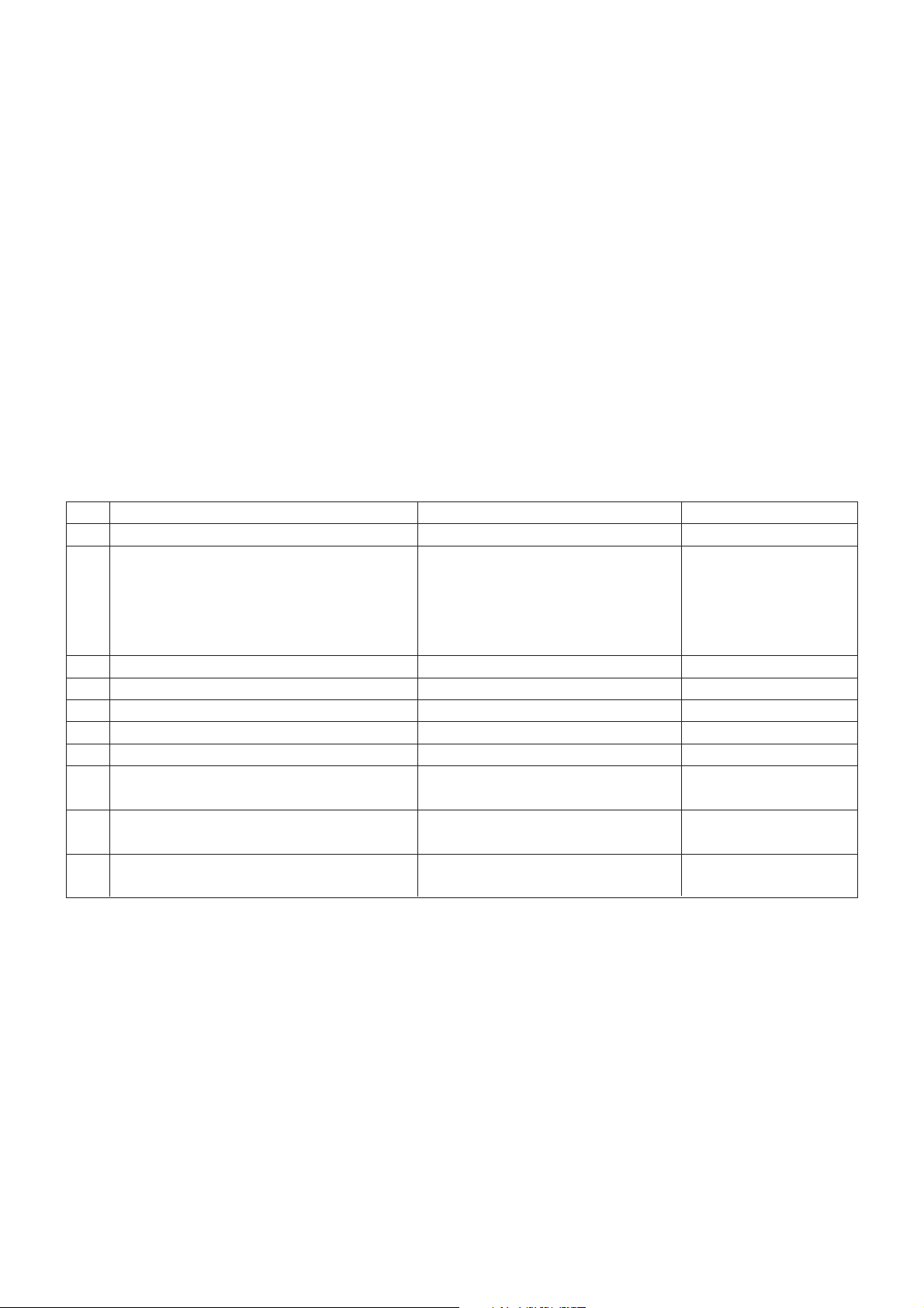
4. General Specification(TV)
No Item Specification Remark
1 Receiving System VSB/64 & 256 QAM/ NTSC-M
2 Available Channel 1) VHF : 02~13
2) UHF : 14~69
3) DTV : 02-69
4) CATV : 01~135
5) CADTV : 01~135
3 Input Voltage 1) AC 100 ~ 240V 50/60Hz
4 Market NORTH AMERICA
5 Screen Size 37, 42 inch Wide
6 Aspect Ratio 16:9
7 Tuning System FS
8 LCD Module LC370WX3-SLD1 LG Philips LCD
LC420WX6-SLD1
9 Operating Environment 1) Temp : 0 ~ 40 deg
2) Humidity : ~ 80 %
10 Storage Environment 1) Temp. : -20 ~ 50 deg
2) Humidity : 10 ~ 90 %
1. Application range
This specification is applied to LA64A chassis.
2. Requirement for Test
Testing for standard of each part must be followed in below
condition.
(1) Temperature : 20 ± 5°C
(2) Humidity : 65% ± 10%
(3) Power : Standard input voltage (100-240V~, 50/60Hz)
*Standard Voltage of each products is marked by
models(4) Specification and performance of each parts are
followed each drawing and specification by part number in
accordance with BOM.
(5) The receiver must be operated for about 20 minutes prior
to the adjustment.
3. Test method
3.1 Performance : LGE TV test method followed
3.2 Demanded other specification
Safety : UL, CSA, IEC Specification
EMC : FCC, ICES, IEC
Page 7

LGE Internal Use OnlyCopyright © 2008 LG Electronics. Inc. All right reserved.
Only for training and service purposes
- 7 -
5. Chroma & Brightness
No Item Min Typ Max Unit Remark
1 White brightness 400 500 cd/m
2
EZ Picture: Daylight, Color
Temperature: Medium
2 Color coordinate RED X 0.602 0.632 0.662 Full Signal Swing
(Default) Y 0.312 0.342 0.372 ± 0.025
GREEN X 0.258 0.288 0.318
Y 0.580 0.610 0.640
BLUE X 0.117 0.147 0.177
Y 0.035 0.065 0.095
WHITE X 0.246 0.287 0.296
Y 0.254 0.289 0.304
3 Brightness uniformity 80 % Full white
4 Contrast ratio 600:1 800:1 EZ Picture: Daylight, Color
Temperature: Medium
5 Color Temperature Standard 8,300 9,300 10,300 oK
Cool 10,000 11,000 12,000 oK
Warm 5,500 6,500 7,500 oK
6. Component Video Input (Y, CB/PB, CR/PR)
No Resolution H-freq(kHz) V-freq.(kHz) Proposed
1 720*480 15.73 59.94 SDTV ,DVD 480I
2 720*480 15.73 60.00 SDTV ,DVD 480I
3 720*480 31.47 59.94 SDTV 480P
4 720*480 31.50 60.00 SDTV 480P
5 1280*720 44.96 59.94 HDTV 720P
6 1280*720 45.00 60.00 HDTV 720P
7 1920*1080 33.72 59.94 HDTV 1080I
8 1920*1080 33.75 60.00 HDTV 1080I
Page 8

LGE Internal Use OnlyCopyright © 2008 LG Electronics. Inc. All right reserved.
Only for training and service purposes
- 8 -
7. RGB Input (PC/DTV)
No Resolution H-freq(kHz) V-freq.(Hz) Pixel clock(MHz) Proposed
PC DDC
1 640*350 31.469 70.08 25.17 DOS X
2 640*480 31.469 59.94 25.17 VESA(VGA) O
3 640*480 37.861 72.80 31.50 VESA(VGA) O
4 640*480 37.500 75.00 31.50 VESA(VGA) O
5 800*600 35.156 56.25 36.00 VESA(SVGA) O
6 800*600 37.879 60.31 40.00 VESA(SVGA) O
7 800*600 48.077 72.18 50.00 VESA(SVGA) O
8 800*600 46.875 75.00 49.50 VESA(SVGA) O
9 1024*768 48.363 60.00 65.00 VESA(XGA) O
10 1024*768 56.476 70.06 75.00 VESA(XGA) O
11 1024*768 60.023 75.02 78.75 VESA(XGA) O
12 1280*768 47.700 60.000 80.140 VESA(WXGA)
1360*768 47.720 59.799 84.750 VESA(WXGA)
1366*768 47.130 59.658 72.000 VESA(WXGA)
DTV
1 720*480 31.50 59.94 SDTV 480P
2 720*480 31.47 60.00 SDTV 480P
3 1280*720 44.96 59.94 HDTV 720P
4 1280*720 45.00 60.00 HDTV 720P
5 1920*1080 33.72 59.94 HDTV 1080I
6 1920*1080 33.75 60.00 HDTV 1080I
8. HDMI1 Input (PC/DTV)
No Resolution H-freq(kHz) V-freq.(Hz) Pixel clock(MHz) Proposed
PC DDC
1 640*480 31.469 59.94 25.17 VESA(VGA) O
2 640*480 37.861 72.80 31.50 VESA(VGA) O
3 640*480 37.500 75.00 31.50 VESA(VGA) O
4 800*600 35.156 56.25 36.00 VESA(SVGA) O
5 800*600 37.879 60.31 40.00 VESA(SVGA) O
6 800*600 48.077 72.18 50.00 VESA(SVGA) O
7 800*600 46.875 75.00 49.50 VESA(SVGA) O
8 1024*768 48.363 60.00 65.00 VESA(XGA) O
9 1024*768 56.476 70.06 75.00 VESA(XGA) O
10 1024*768 60.023 75.02 78.75 VESA(XGA) O
11 1280*768 47.700 60.00 80.140 VESA(WXGA) O
12 1360*768 47.720 59.799 84.750 VESA(WXGA) O
13 1366*768 47.130 59.658 72.000 VESA(WXGA) O
DTV
1 720*480 31.500 59.94 27.00 SDTV 480P
2 720*480 31.469 60.00 27.03 SDTV 480P
3 1280*720 44.96 59.94 HDTV 720P
4 1280*720 45.00 60.00 HDTV 720P
5 1920*1080 33.72 59.94 HDTV 1080I
6 1920*1080 33.75 60.00 HDTV 1080I
Page 9

LGE Internal Use OnlyCopyright © 2008 LG Electronics. Inc. All right reserved.
Only for training and service purposes
- 9 -
10. General specifications (module)
10-1. 37LC5DC
No Item Value Unit Remark
1 Active Screen Size 940.3(diagonal) mm 37.02 inches
2 Outline Dimension 877.0(H)x516.8(V)x46.9(D) mm
3 Pixel Pitch 200 x 600 x RGB um
4 Pixel Format 1366(H)x768(V) stripe arrangement
5 Color Depth 8bit 16.7 Mbit
6 Luminance ,White 500 (center 1 point typ) cd/m2
7 Viewing Angle (CR>10) R/L 178(Typ),U/D 178(Typ) degree
8 Power Consumption 126 Watt
9 Weight 9 kg
10 Display Operating Mode Transmissive mode, normally black
11 Surface Treatment Hard coating (3H)
10-2. 42LC5DC
No Item Value Unit Remark
1 Active Screen Size 1067.308 (diagonal) mm 42.02 inches
2 Outline Dimension 983(H)x576(V)x47.3(D) mm
3 Pixel Pitch 227 x 681 x RGB um
4 Pixel Format 1366(H)x768(V) stripe arrangement
5 Color Depth 8bit 16.7 Mbit
6 Luminance ,White 450 (center 1 point typ) cd/m2
7 Viewing Angle (CR>10) R/L 178(Typ),U/D 178(Typ) degree
8 Power Consumption 168.36 Watt
9 Weight 110(Typ), 12(Max) kg
10 Display Operating Mode Transmissive mode ,normally black
11 Surface Treatment Hard coating (3H)
9. HDMI2 Input (DTV)
No Resolution H-freq(kHz) V-freq.(Hz) Pixel clock(MHz) Proposed
1 720*480 31.500 59.94 27.00 SDTV 480P
2 720*480 31.469 60.00 27.03 SDTV 480P
3 1280*720 44.96 59.94 HDTV 720P
4 1280*720 45.00 60.00 HDTV 720P
5 1920*1080 33.72 59.94 HDTV 1080I
6 1920*1080 33.75 60.00 HDTV 1080I
Page 10

LGE Internal Use OnlyCopyright © 2008 LG Electronics. Inc. All right reserved.
Only for training and service purposes
- 10 -
11. Electro Optical Characteristic Specifications (module standard)
11-1. 37LC5DC
No Item Min Typ Max Unit Remark
1 Contrast Ratio(CR) 700 900
2 Surface Luminance, White 400 500 Cd/m
2
Full white
3 Luminance Variation 1.3 (δwhite/5P)
4 Response Time Gray to Gray 6 10 msec
5 Color coordinate RED X Typ 0.636 Typ Full Pattern
Y -0.03 0.343 +0.03
GREEN X 0.284
Y 0.615
BLUE X 0.144
Y 0.063
WHITE X 0.279
Y 0.292
6 Viewing Angle (CR>10) X axis right(ø=0) 85 89 degree
X axis left(ø=180) 85 89
Yaxis up (ø=90) 85 89
Z axis down(ø=270) 85 89
11-2. 42LC5DC
No Item Min Typ Max Unit Remark
1 Contrast Ratio CR 800 1000
CR with DCR TBD TBD
2 Surface Luminance, White 400 450 Cd/m
2
Full white
3 Luminance Variation 1.3 (δwhite/5P)
4 Response Time Gray to Gray 5 18 msec
Rise+decay 10 14
5 Color coordinate RED X Typ 0.635 Typ Full Pattern
Y -0.03 0.344 +0.03
GREEN X 0.286
Y 0.614
BLUE X 0.146
Y 0.061
WHITE X 0.279
Y 0.292
6 Viewing Angle (CR>10) X axis right(ø=0) 85 89 degree
X axis left(ø=180) 85 89
Yaxis up (ø=90) 85 89
Z axis down(ø=270) 85 89
7 Gray Scale Without DCR 2.2
With DCR
Page 11

LGE Internal Use OnlyCopyright © 2008 LG Electronics. Inc. All right reserved.
Only for training and service purposes
- 11 -
12. Customer Menu Setup (Shipment Condition)
No Item Condition Remark
1 Input Mode TV02CH
2 Volume Level 20
3 Mute Off
4 Aspect Ratio 16:9
5 Video EZ Picture Daylight
Color temperature (Disable)
Can be access only EZ picture is setting user mode
XD Auto
Advanced Cinema: Off
Reset
6 Audio Audio Language Off
EZ SoundRite Off
EZ Sound Normal
Balance 0
Treble 50
Bass 50
Front Surround Off
TV Speaker On
7 Timer Auto clock Off
Manual Clock Off
Off Timer Off
On Timer Off
Auto Off Off
8 Option Aspect Ratio 16:9
Caption/Text Off
Caption Option Off
Language English
ISM Method Normal
SET ID 1
9 Lock Lock System Off
Set password On ( Default : 0000 )
Block channel None
Movie Rating Off
TV Rating-Children Off
TV Rating-General Off
Audio Block Off
10 Channel Memory none
Page 12

LGE Internal Use OnlyCopyright © 2008 LG Electronics. Inc. All right reserved.
Only for training and service purposes
- 12 -
ADJUSTMENT INSTRUCTION
1. Application Range
This spec sheet is applied all of the 'LA64A' Chassis.
2. Specification
2.1 Because this is not a hot chassis, it is not necessary to use
an isolation transformer. However, the use of isolation
transformer will help protect test instrument.
2.2 Adjustment must be done in the correct order.
2.3 The adjustment must be performed in the circumstance of
25±5°C of temperature and 65±10% of relative humidity if
there is no specific designation.
2.4 The input voltage of the receiver must keep 100~240V, 60Hz.
2.5 The receiver must be operated for about 15 minutes prior to
the adjustment.
O After RGB Full White in HEAT-RUN Mode, the receiver
must be operated prior to the adjustment.
O Enter into HEAT-RUN MODE
(1) Press the POWER ON KEY on R/C for adjustment.
(2) OSD display and screen display 100% full WHITE
PATTERN.
- Set is activated HEAT run without signal generator in
this mode.
- Single color pattern (RED / BLUE / GREEN) of HEAT
RUN MODE uses to check panel.
- Caution: If you turn on a still screen more than 20
minutes (Especially digital pattern, cross hatch
pattern), an after image may be occur in the black
level part of the screen.
3. Adjustment items
=> Use cross connected RS-232C Cable. Don°Øt use straightly
connected RS-232C Cable.
(Pin Connection: 1-1, 2-3, 3-2, 4-4, 5-5, 6-6, 7-7, 8-8, 9-9)
O Method of PTC MICOM Download
O Select method of Module type
O Auto AV (CVBS) Color Balance adjustment.
- Standard equipment: 802F Pattern Generator. Master
Pattern Generator (MSPG-925, etc) or same product
O Auto Component Color Balance adjustment.
- tandard equipment: 802F Pattern Generator. Master
Pattern Generator (MSPG-925, etc) or same product
O Auto RGB Color Balance adjustment.
- Standard equipment: PC Pattern Generator(VG828,
VG854, 801GF, MSP3240A, MSPG-925, etc) or same
product
O Auto RF Color Balance adjustment.
- RF 2CH
O EDID/DDC Data input.
O Adjustment of White Balance.
O Factoring Option Data input.
4. Method of PTC MICOM Download
4.1 Connection of MICOM JIG
1) Connect port(3) with Power Code
2) Connect jack(1) with PTC Micom.
3) Connect USB Cable to the computer
4) Download Program execution (SAP Configuration)
* Notice!
Because PTC Download JIG has internal memory, it can save
download files using download program (SAP Configuration).
Push the START button (4) after file saving, then it execute
download.
4.2 Execution of download program (SAP Configuration)
4.2.1 Execution of SAP Configuration
<SAP Configuration>
1
2
3
5
4
Page 13

LGE Internal Use OnlyCopyright © 2008 LG Electronics. Inc. All right reserved.
Only for training and service purposes
- 13 -
1) Select HCS12
2) Target Frequency Settings :
A. Checking the factor -> Use Specified Target Frequency
..., Unsecure target....
B. Insert Target Bus Frequency -> 7372800
3) Specify Algorithm: 9S12dt128_128k .12P
4) Specify S Record: select download file.
5) Checking factor: Erase Device, Blank Check Device,
Program Device, Verify Device
* Notice!
Don't check other checking boxes. You must follow fig.
6) Push the 'Save Image to Cyclone PRO' button, files
transfer from PC to the Download JIG.
5. Select method of Module type
5.1 Setting up like figure
(Setting: Press ADJ Key in the Adjust remocon.
Select "System Control 3" by using
D/E (CH+/-) key, and press
A(ENTER)
Using Adjust remocon, select module)
6. Color Balance adjustment.
6.1 Auto AV (CVBS) Color Balance
6.1.1 Required Equipment
- Remote controller for adjustment
- AV Pattern Generator: 802F Pattern Generator, Master
(MSPG-925FS), etc
(Which has NTSC-J Composite Video format output with
standard (1.0 Vpp) See Fig. 1)
- It is very import to use correct adjustment pattern like
Fig.1.
6.1.2 Method of Auto AV (CVBS) Color Balance
1) Input the NTSC-J Composite Video (Fig.1.) into video
input.
=> MSPG-925FS Model No: 207 / Pattern No: 65 / NTSC-J
2) Set the EZ Picture to Daylight mode in Video menu.
3) Press INSTART key on R/C for adjustment.
4) Press the
G(Vol. +) key operate to set, then it becomes
automatically.
5) Auto-RGB OK means completed adjustment.
* When adjust main picture, sub picture is included.
PC -> Download Jig
<Fig.1> Auto AV (CVBS) Color Balance Test Pattern
Default Value on OSD
Before ADC Calibration, should be executed the "Module type
selection".
Auto Color Balance (Hex)
Auto-RGB G To Set
Source Main
Red Offset1 102
Green Offset1 0C6
Blue Offset1 0DA
Red Offset2 3F
Green Offset2 3F
Blue Offset2 3F
Red Gain 072
Green Gain 070
Blue Gain 07B
Reset
G To Set
Page 14

LGE Internal Use OnlyCopyright © 2008 LG Electronics. Inc. All right reserved.
Only for training and service purposes
- 14 -
6.2 Auto Component Color Balance
6.2.1 Required Test Equipment
- Remote controller for adjustment
- 802F Pattern Generator Which has 720p YPbPr output
with Standard (0.7Vpp) See Fig. 2
- It is very important to use correct adjustment pattern like
Fig. 2.
6.2.2 Method of Auto Component Color Balance
1) Input the Component 1280*720p 60Hz signal into
Component.
=> MSPG-925FS Model No: 217 / Pattern No: 65
2) Set the EZ Pictures to Daylight mode in Video menu.
3) Press INSTART key on R/C for adjustment.
4) Press the
G(Vol. +) key operate To set, then it becomes
automatically.
5) Auto-RGB OK means completed adjustment
6.3 Auto RGB Color Balance
6.3.1 Required Test Equipment
- Remote controller for adjustment
- 802F Pattern Generator, Master (MSPG-925FS), etc.
(Which has XGA 60Hz PC Format output with standard
(0.7Vpp) See Fig. 3 )
- It is very import to use correct adjustment pattern like Fig.
3.
6.3.2 Method of Auto RGB Color Balance
1) Input the PC 1024x768 @ 60Hz into RGB.
=> MSPG-925FS Model No: 60 / Pattern No: 65
2) Set the EZ Pictures to Daylight mode in Video menu.
3) Press INSTART key on R/C for adjustment.
4) Press the
G(Vol. +) key operate To set, then it becomes
automatically.
5) Auto-RGB OK means completed adjustment.
<Fig.2> Auto Component Color Balance Test Pattern
Default Value on OSD
Auto Color Balance (Hex)
Auto-RGB G To Set
Source Main
Red Offset1 0F8
Green Offset1 0DA
Blue Offset1 0BC
Red Offset2 01
Green Offset2 01
Blue Offset2 01
Red Gain 1FE
Green Gain 1FE
Blue Gain 1FE
Reset G To Set
<Fig.3> Auto RGB Color Balance Test Pattern
Default Value on OSD
Auto Color Balance (Hex)
Auto-RGB G To Set
Source Main
Red Offset1 069
Green Offset1 0DA
Blue Offset1 0D0
Red Offset2 37
Green Offset2 39
Blue Offset2 3F
Red Gain 19F
Green Gain 183
Blue Gain 195
Reset G To Set
Page 15

6.4 RF Color Balance
1) Input the RF cable(2 ch)
2) Set the EZ Pictures to Daylight mode in Video menu.
3) Press INSTART key on R/C for adjustment.
4) Press the
G(Vol. +) key operate To set, then it becomes
automatically.
5) Auto-RGB OK means completed adjustment
7. EDID / DDC INPUT
7.1 EDI D(The Extended Display Identification Data) /
DDC(Display Data Channel) download
7.1.1 Required Test Equipment
1) Adjusting PC with S/W for writing EDID Data.
2) A Jig for EDID Download
3) Cable: Serial (9Pin or USB) to D-sub 15Pin cable, D-sub
15Pin cable, DVI to HDMI cable.
7.1.2 Setting of device
- When input HDMI EDID data through RGB or HDMI jack,
writing 8bits of the data at every turn with 'DDC2B'
protocol.
- 15 -
LGE Internal Use OnlyCopyright © 2008 LG Electronics. Inc. All right reserved.
Only for training and service purposes
Default Value on OSD
Auto Color Balance (Hex)
Auto-RGB G To Set
Source Main
Red Offset1 032
Green Offset1 030
Blue Offset1 033
Red Offset2 40
Green Offset2 40
Blue Offset2 40
Red Gain 03C
Green Gain 03C
Blue Gain 01F
Reset G To Set
<Fig.4> Connection Diagram of DDC download
Page 16

7.1.3 Data of EDID for 32/37/42LC5DC-UA,32LX5DC-UA
7.1.3.1 DDC data of Analog-RGB
7.1.3.2 DDC data of Digital-HDMI1
7.1.3.3 DDC data of Digital-HDMI2
8. Adjustment of White Balance
8.1 Required Equipment
- Remote controller for adjustment
- Color Analyzer (CA-210 or same product )
- Auto W/B adjustment instrument(only for Auto adjustment)
- Use inner(SELF) Pattern
8.2 Adjustment of White Balance (For Manual adjustment)
Set TV input to RF.
Operate the zero-calibration of the CA-210, Ch.9.
Then stick sensor to LCD module surface when you adjust.
For manual adjustment, it is also possible by the following
sequence.
1) Select white pattern of heat-run mode by pressing power
on key on remote control for adjustment then operate
heat run more than 15 minutes.
2) Enter the White Balance adjustment mode by pressing
the INSTART key twice (White Balance) on R/C.
3) Stick sensor to center of the screen and select each
items using
D/E(CH +/-) key on R/C.
4) Adjust G Gain / B Gain using
F/G(VOL +/-) key on R/C.
5) Adjust it until color coordination becomes as below.
- By controlling G, B GAIN, adjust X, Y target value.
- R Gain fixed at cool, normal, warm mode.
- But, Control the R GAIN, unless it has correct value
(Initially, R/G/B gain and R/G/B offset values are fixed as below.)
Red Gain: 80h Green Gain: 80h Blue Gain: 80h
Red Offset: 80h Green Offset: 80h Blue Offset: 80h
*Target value
X Y Temp (∆uv)
Cool 0.276 ± 0.002 0.283 ± 0.002 11000k (0.000)
Normal 0.285 ± 0.002 0.293 ± 0.002 9300k (0.000)
Warm 0.313 ± 0.002 0.329 ± 0.002 6500k (0.003)
6) When adjustment is completed, Exit adjustment mode
using EXIT key on R/C.
- 16 -
LGE Internal Use OnlyCopyright © 2008 LG Electronics. Inc. All right reserved.
Only for training and service purposes
Before adjustment of white balance, should be executed the
'color balance adjustment'
Page 17

9. Auto white Balance (AV)
command1 command2 Set ID Data Default value
Min Max
Input Select
x b 01 20h 90h
R-Gain j a 01 0h FEh 77h
G-Gain j b 01 0h FEh 80h
B-Gain j c 01 0h FEh 7ch
R-Offset j d 01 0h FEh 7ch
G-Offset j e 01 0h FEh 80h
B-Offset j f 01 0h FEh 8ch
10. Test factor for commercial model
10.1 IR In/ Out Check
10.1.1 Check Order 'Pass' Judgment
1) Insert RJ45 Cable, RS-232C Cable 2EA. Phone Jack to
each Port as below Picture.
2) Change the Mode 'PTC Only' On OSD(In-start -> Uart
Control -> Download -> PTC°±)
3) Running the 'IR/MPI Check Program' on PC
4) Click the 'AUTO Run' or 'Push the Spacebar' on the
keyboard
5) If the Sign is 'NG' try One More as 'Push the Spacebar'
6) Confirm the 'OK' Sign on Screen that means IR in & MPI
Test Pass / 'NG' Sign is NG
Confirm the 'PASS' Sign of IR Out Check JIG / 'NG' Sign
is NG
7) After finish Check. Change the Mode 'D-Box On'(In-start
-> Uart Control -> D-Box 'ON')
10.1.2 Needs JIG & Equip. & Cable
PC('MPI/IP In' Check Program. RS-232C 2Port), IR Out
Check Jig(With level Shifter), 232C to Phone jack Cable, 5V
Adapter, 232C Cable(Cross) 232C Cable(Cross) 2EZ,
RJ45(Direct) Cable.
10.2 Lodgenet Card & Auto Camport Check
10.3 RJP(Remote Jack Pack) Check
10.3.1 Check Order 'Pass' Judgment
1) Connecting RJP Test JIG & RJP Port of Set with Modem
Cable(8Pin)
2) Check the RJP operation on OSD(In-start -> RJP Pin
Check ->
G
3) 'SUCCESS! PIN CONNECTION OK' -> PASS
4) 'Pin Check Fail!!!!' -> NG
5) If the Result is 'NG', try One More
10.3.2 Needs JIG & Equip. & Cable
1) RJP Check JIG, Modem Cable (8 Pin)
10.4 MPI Card Check
- 17 -
LGE Internal Use OnlyCopyright © 2008 LG Electronics. Inc. All right reserved.
Only for training and service purposes
Page 18

LGE Internal Use OnlyCopyright © 2008 LG Electronics. Inc. All right reserved.
Only for training and service purposes
- 18 -
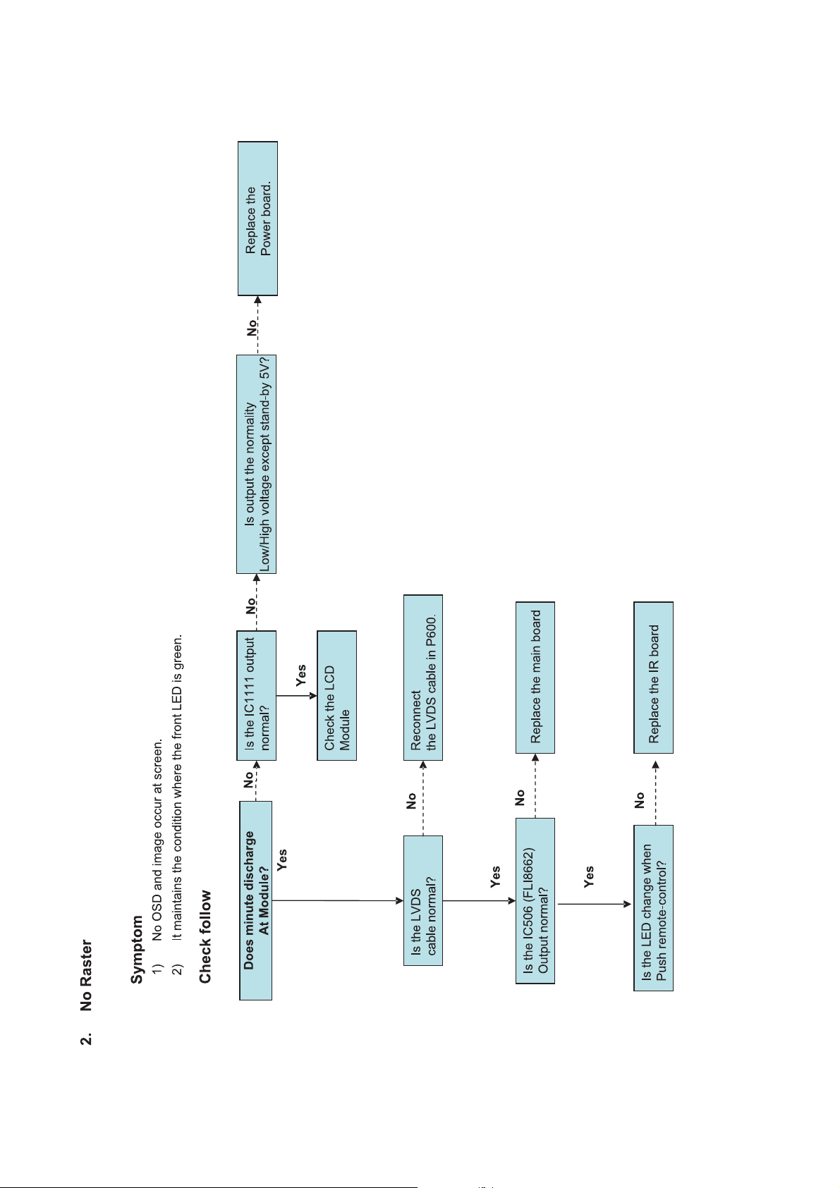
TROUBLESHOOTING
Page 19

LGE Internal Use OnlyCopyright © 2008 LG Electronics. Inc. All right reserved.
Only for training and service purposes
- 19 -
Page 20
LGE Internal Use OnlyCopyright © 2008 LG Electronics. Inc. All right reserved.
Only for training and service purposes
- 20 -
Page 21

LGE Internal Use OnlyCopyright © 2008 LG Electronics. Inc. All right reserved.
Only for training and service purposes
- 21 -
Page 22

LGE Internal Use OnlyCopyright © 2008 LG Electronics. Inc. All right reserved.
Only for training and service purposes
- 22 -
Page 23

LGE Internal Use OnlyCopyright © 2008 LG Electronics. Inc. All right reserved.
Only for training and service purposes
- 23 -
Page 24

BLOCK DIAGRAM
- 24 -
LGE Internal Use OnlyCopyright © 2008 LG Electronics. Inc. All right reserved.
Only for training and service purposes
1. Overall Block Diagram (D2A + BCM7411 + Cortez Adv.)
DIGIT_D[0-23]
H,V_SYNC_DIGIT
DE,CLK_DIGIT
D2A_VIDEO_OUT
TMDS_0
TMDS_1
DDC_I2C_0,1
EEPROM
_1
EEPROM
_0
TUNER_CVBS
ATSC/NTSC
Tuner
R,G,B
VGA_H,V SYNC
CABLE_DET
COMPONENT
(Y,Pb,Pr)
COMPONENT (Y,Pb,Pr)
REAR CVBS
SIDE_CVBS
S_VIDEO Y,C(rear/side)
S_VIDEO DET
TUNER_CVBS
I2S
Comp_1/2 L/R
MSP L/R
Analog L/R
CVBS,S-VIDEO L/R
VGA L/R
MNT_OUT_L/R
SPDIF_OUT
IR
I2C_D2A
(AT)
I2C_Cortez
(NT)
I2C_Cortez
SIDE L/R
D2A
UART_D2A_0
RS232
232C_Tx / Rx
MSP4450K
TPA3100D2
I2C_Cortez
MNT_V_OUT
INV_BR
DIGITAL_IN[24Bit]
DE,CLK_IN
DIGITAL_H,V_SYNC
ANALOG_IN
ANALOG_H,V_SYNC
ANALOG_IN
CABLE_DET
ANALOG_IN
ANALOG_IN
ANALOG_IN
ANALOG_IN
ANALOG IN
INV_BRI
DISPLAY_EN
AI_ON_OFF/OD
SEL_1
LVDS_DATA
LVDS_DATA
DISPLAY_EN
INV_CTL
IR
UART1
UART1
LVDS
Conne cto r
For LCD
POWER
HDMI
SiI9023
NVRAM
EEPROM
16 KB
DDRRAM
(256 Mb )
$4
Flash
2MB
$1
232C Driver
ST3232CDR
NVRAM
EEPROM
32KB
AT49BV160C
F-ROM (2MB)
$ 0.46
DDRRAM
(32MB)
$2.7
I2C MUX
S
I
F
_
T
U
N
E
R
I2S
I2S
NJU26901
ANT./Cable
I2C_D2A
VSB
Pro:Idiom
BCM7411
DDRRAM
(128 MB )
I2S
CPLD
12_to_24
EBI
8_to_16
8
16
DIGITAL_IN[24Bit]
DE,CLK_IN
DIGITAL_H,V_SYNC
UART_D2A_1
SERIAL_TS
I2S
DIGIT_D[0-23]
H,V_SYNC_DIGIT
DE,CLK_DIGIT
Cortez-A.
FLI8662
UART
MUX
UART0
UART0
MSP SPDIF
Paral lel To Serial
SPDIF
MUX
7411 SPDIF
D2A SPDIF
D2A SPDIF
I2S
MUX
Impl emented
in CPLD
I2C_Cortez_5V
Page 25

- 25 -
LGE Internal Use OnlyCopyright LG Electronics. Inc. All right reserved.
Only for training and service purposes
802
808
801
809
520
510
500
300
120
200
800
803
804
807
805
700
600
530
610
601
910
900
620
710
540
400
811
810
806
200T
200N
EXPLODED VIEW
Many electrical and mechanical parts in this chassis have special safety-related characteristics. These
parts are identified by in the Schematic Diagram and EXPLODED VIEW.
It is essential that these special safety parts should be replaced with the same components as
recommended in this manual to prevent X-RADIATION, Shock, Fire, or other Hazards.
Do not modify the original design without permission of manufacturer.
IMPORTANT SAFETY NOTICE
Page 26

LGE Internal Use
Only
Copyright © 2008 LG Electronics. Inc. All right reserved.
Only for training and service purposes
Page 27

LGE Internal Use
Only
Copyright © 2008 LG Electronics. Inc. All right reserved.
Only for training and service purposes
Page 28

LGE Internal Use
Only
Copyright © 2008 LG Electronics. Inc. All right reserved.
Only for training and service purposes
Page 29

LGE Internal Use
Only
Copyright © 2008 LG Electronics. Inc. All right reserved.
Only for training and service purposes
Page 30

Jun., 2008
Printed in KoreaP/NO : MFL36550709
 Loading...