

LG 37LC50 Owner's Manual [es]

User’s Guide Specification
User’s Guide Specification
Model Description
1.
MODEL
SUFFIX
2.
32/37/42LC5DC
32LX5DC/42PX8DC
PANAMA
Printing Specification
1. Trim Size (Format) : 185 mm x 260 mm
2. Printing Colors
• Cover : 1 COLOR (BLACK)
•Inside : 1 COLOR (BLACK)
3. Stock (Paper)
• Cover : Coated paper , Snow White 150 g/㎡
• Inside : Uncoated paper , 백상지 60 g/㎡
4. Printing Method : OFF-SET
5. Bindery : Perfect Bind
6. Language : English/Spanish
7. Number of pages : 180
BRAND
Product Name
LG
32/37/42LC5DC,32LX5DC,
42PX8DC
담 당 관리자
KIM WON
MI
08.01.02
Part No.
KANG KWANG
SUK
08.01.02
MFL34797070
(0904-REV01)
“This part contain Eco-hazardous substances (Pb, Cd, Hg, Cr6+, PBB, PBDE, etc.) within LG standard level,
N
O
T
E
S
Details should be followed Eco-SCM management standard[LG(56)-A-2524].
Especially, Part should be followed and controlled the following specification.
(1)Eco-hazardous substances test report should be submitted
when Part certification test and First Mass Production.
(2) Especially, Don’t use or contain lead(Pb) and cadmium(Cd) in ink.
Special Instructions3.
(1) Origin Notification
* LGESY : China * LGEVN : Vietnam * LGEEG : Egypt * LGEAZ : Brazil
* LGENP : China * LGETH : Thailand * LGEMA : Poland
* LGEIN : Indonesia * LGEIL : India * LGERA : Russia
* LGEDI : Indonesia * LGEAK : Kazakhstan * LGERS : Mexico
4.
Changes
9
8
7
6
5
4
2
1
April./16/09 Kim won mi S9-50216
REV.
NO.
MM/DD/YY
SIGNATURE
CHANGE NO.
[ LA64A ] Add the model name in the manual.
CHANGE CONTENTS

Front cover
LG(EN)
P/No.
LG(SP)
Pagination sheet
Pagination sheet
1
…
…
P/NO. MFL34797070
Total pages : 180 pages
LG
87
Rear cover
LG
1
…
…
87
Please read this manual carefully before operating
your set.
Retain it for future reference.
Record model number and serial number of the set.
See the label attached on the back cover and quote
this informa tion to your dealer
when you require service.
LCD TV
OWNER’S MANUAL
32LC5DC
32LC5DCS
32LC5DCB
37LC5DC
37LC5DCB
37LC5DC1
42LC5DC
32LX5DC
32LX5DCS
42LB5DC
32LC50C
32LC50CS
32LC50CB
32LX50C
32LX50CS
37LC50
37LC50CB
42LB50C
42LC50C
www.lgcommercial.com
PLASMA TV MODEL
42PX8DC
PLASMA TV
P/NO : MFL34797070 (0904-REV01)
LCD TV MODELS
MFL34797070en-1 4/16/09 2:14 PM Page 1

MFL34797070en-1 4/16/09 2:14 PM Page 2

1
SAFETY INSTRUCTION
IMPORTANT SAFETY INSTRUCTIONS
Read these instructions.
Keep these instructions.
Heed all warnings.
Follow all instructions.
Do not use this apparatus near water.
Clean only with dry cloth.
Do not block any ventilation openings. Install in
accordance with the manufacturer’s instructions.
Do not install near any heat sources such as
radiators, heat registers, stoves, or other apparatus
(including amplifiers)that produce heat.
.
Protect the power cord from being walked on
or pinched particularly at plugs, convenience
receptacles, and the point where they exit from
the apparatus.
Only use attachments/accessories specified by
the manufacturer.
Use only with the cart, stand, tripod, bracket,
or table specified by the manufacturer, or sold
with the apparatus. When a cart is used, use
caution when moving the cart/apparatus
combination to avoid injury from tip-over.
Unplug this apparatus during lighting storms or
when unused for long periods of time.
Refer all servicing to qualified service personnel.
Servicing is required when the apparatus has been
damaged in any way, such as power-supply cord or
plug is damaged, liquid has been spilled or objects
have fallen into the apparatus, the apparatus has
been exposed to rain or moisture, does not operate
normally, or has been dropped.
1
2
3
4
6
7
5
8
9
MFL34797070en-1 4/16/09 2:14 PM Page 1
2
SAFETY INSTRUCTION
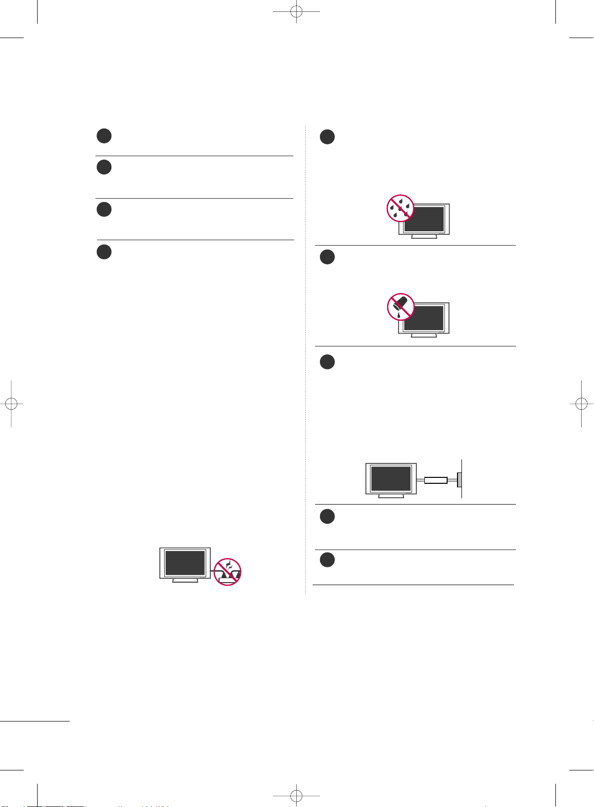
Never touch this apparatus or antenna during a
thunder or lighting storm.
When mounting a TV on the wall, make sure not to
install the TV by the hanging power and signal
cables on the back of the TV.
Do not allow an impact shock or any objects to fall
into the product, and do not drop onto the screen
with something.
CAUTION concerning the Power Cord :
It is recommend that appliances be placed upon a
dedicated circuit; that is, a single outlet circuit which
powers only that appliance and has no additional
outlets or branch circuits. Check the specification
page of this owner's manual to be certain.
Do not connect too many appliances to the same
AC power outlet as this could result in fire or electric shock.
Do not overload wall outlets. Overloaded wall outlets, loose or damaged wall outlets, extension cords,
frayed power cords, or damaged or cracked wire
insulation are dangerous. Any of these conditions
could result in electric shock or fire. Periodically
examine the cord of your appliance, and if its
appearance indicates damage or deterioration,
unplug it, discontinue use of the appliance, and
have the cord replaced with an exact replacement
part by an authorized servicer. Protect the power
cord from physical or mechanical abuse, such as
being twisted, kinked, pinched, closed in a door, or
walked upon. Pay particular attention to plugs, wall
outlets, and the point where the cord exits the
appliance.
Do not make the TV with the power cord plugged
in. Do not use a damaged or loose power cord. Be
sure do grasp the plug when unplugging the power
cord. Do not pull on the power cord to unplug the
TV.
WARNING - To reduce the risk of fire or electrical
shock, do not expose this product to rain, moisture
or other liquids. Do not touch the TV with wet
hands. Do not install this product near flammable
objects such as gasoline or candles or expose the
TV to direct air conditioning.
Do not expose to dripping or splashing and do not
place objects filled with liquids, such as vases, cups,
etc. on or over the apparatus (e.g. on shelves above
the unit).
GGRROOUUNNDDIINNGG
Ensure that you connect the earth ground wire to
prevent possible electric shock. (i.e. a TV with a
three-prong grounded AC plug must be connected
to a three-prong grouned AC outlet) If grounding
methods are not possible, have a qualified electrician install a separate circuit breaker.
Do not try to ground the unit by connecting it to
telephone wires, lightening rods, or gas pipes.
DDIISSCCOONNNNEECCTTIINNGG DDEEVVIICCEE FFRROOMM MMAAIINNSS
Mains plug is the disconnecting device. The plug
must remain readily operable.
Keep the product away from direct sunlight.
11
10
13
12
15
16
17
18
Power
Supply
Short-circuit
Breaker
14
MFL34797070en-1 4/16/09 2:14 PM Page 2

3
Cleaning
When cleaning, unplug the power cord and scrub
gently with a soft cloth to prevent scratching. Do not
spray water or other liquids directly on the TV as
electric shock may occur. Do not clean with chemicals such as alcohol, thinners or benzene.
Moving
Make sure the product is turned off, unplugged
and all cables have been removed. It may take 2 or
more people to carry larger TVs. Do not press
against or put stress on the front panel of the TV.
Ventilation
Install your TV where there is proper ventilation. Do
not install in a confined space such as a bookcase.
Do not cover the product with cloth or other materials (e.g.) plastic while plugged in. Do not install in
excessively dusty places.
If you smell smoke or other odors coming from the
TV or hear strange sounds, unplug the power cord
contact an authorized service center.
Do not press strongly upon the panel with a hand or
sharp object such as nail, pencil or pen, or make a
scratch on it.
21
19
22
23
20
MFL34797070en-1 4/16/09 2:14 PM Page 3
4
CONTENTS
WARNING / CAUTION
. . . . . . . . . . . . . . . . . . . . . . . . . . . . 1
SAFETY INSTRUCTION
. . . . . . . . . . . . . . . . . . . . . . . . . . . . 2
FEATURE OF THIS TV . . . . . . . . . . . . . . . . . . . . . . . . . . . . . . 6
PREPARATION
Accessories
. . . . . . . . . . . . . . . . . . . . . . . . . . . . . . . . . . . . . . . . . . . . . . . . . . . . . . 7
Front Panel Controls
. . . . . . . . . . . . . . . . . . . . . . . . . . . . . . . . . . . . . . . . . 8
Back Panel Information
. . . . . . . . . . . . . . . . . . . . . . . . . . . . . . . . . . . . . 11
Back Cover for Wire Arrangement
. . . . . . . . . . . . . . . . . . . . . 13
Attaching the TV to a Wall
. . . . . . . . . . . . . . . . . . . . . . . . . . . . . . . 16
Swivel Stand
. . . . . . . . . . . . . . . . . . . . . . . . . . . . . . . . . . . . . . . . . . . . . . . . . . . . 16
Attaching the TV to a Desk
. . . . . . . . . . . . . . . . . . . . . . . . . . . . . . 17
Stand Installation
. . . . . . . . . . . . . . . . . . . . . . . . . . . . . . . . . . . . . . . . . . . . . 18
VESA Wall Mounting . . . . . . . . . . . . . . . . . . . . . . . . . . . . . . . . . . . . . . . .19
Desktop Pedestal Installation
. . . . . . . . . . . . . . . . . . . . . . . . . . . 19
Antenna or Cable Connection
. . . . . . . . . . . . . . . . . . . . . . . . . . 20
EXTERNAL EQUIPMENT SETUP
HD Receiver Setup
. . . . . . . . . . . . . . . . . . . . . . . . . . . . . . . . . . . . . . . . . 21
DVD Setup
. . . . . . . . . . . . . . . . . . . . . . . . . . . . . . . . . . . . . . . . . . . . . . . . . . . . . 24
VCR Setup
. . . . . . . . . . . . . . . . . . . . . . . . . . . . . . . . . . . . . . . . . . . . . . . . . . . . . 26
Other A/V Source Setup
. . . . . . . . . . . . . . . . . . . . . . . . . . . . . . . . 28
Digital Audio Output . . . . . . . . . . . . . . . . . . . . . . . . . . . . . . . . . . . . . . 28
PC Setup . . . . . . . . . . . . . . . . . . . . . . . . . . . . . . . . . . . . . . . . . . . . . . . . . . . . . . . . 29
WATCHING TV / CHANNEL CONTROL
Remote Control Functions . . . . . . . . . . . . . . . . . . . . . . . . . . . . . . . 32
Turning On TV
. . . . . . . . . . . . . . . . . . . . . . . . . . . . . . . . . . . . . . . . . . . . . . . . 34
Channel Selection . . . . . . . . . . . . . . . . . . . . . . . . . . . . . . . . . . . . . . . . . . .34
Volume Adjustment
. . . . . . . . . . . . . . . . . . . . . . . . . . . . . . . . . . . . . . . . . 34
On-Screen Menus Selection . . . . . . . . . . . . . . . . . . . . . . . . . . . . . 35
Channel Setup
. . . . . . . . . . . . . . . . . . . . . . . . . . . . . . . . . . . . . . . . . . . . . . . . 36
- Auto Scan (EZ Scan)
. . . . . . . . . . . . . . . . . . . . . . . . . . . . . . . . . 36
- Add / Delete Channel (Manual Scan)
. . . . . . . . . 37
- Channel Editing
. . . . . . . . . . . . . . . . . . . . . . . . . . . . . . . . . . . . . . . . 38
DTV Signal Strength
. . . . . . . . . . . . . . . . . . . . . . . . . . . . . . . . . . . . . . . . 39
Channel Label
. . . . . . . . . . . . . . . . . . . . . . . . . . . . . . . . . . . . . . . . . . . . . . . . . 40
PICTURE CONTROL
Watching DW (Double Window) . . . . . . . . . . . . . . . . . . . . . . . 41
Picture Size (Aspect Ratio) Control
. . . . . . . . . . . . . . . . . . 43
Preset Picture Settings
- EZ Picture - Preset
. . . . . . . . . . . . . . . . . . . . . . . . . . . . . . . . . . . . 45
- Color Tone - Preset.
. . . . . . . . . . . . . . . . . . . . . . . . . . . . . . . . . . 46
Manual Picture Adjustment
- EZ Picture - User Mode
. . . . . . . . . . . . . . . . . . . . . . . . . . . . 47
- Color Tone - User Mode
. . . . . . . . . . . . . . . . . . . . . . . . . . . 48
XD - Picture Improvement Technology
. . . . . . . . . . . . . 49
Advanced - Cinema Mode
. . . . . . . . . . . . . . . . . . . . . . . . . . . . . . . 50
Advanced - Black (Darkness) Level
. . . . . . . . . . . . . . . . . . . 51
Picture Reset
. . . . . . . . . . . . . . . . . . . . . . . . . . . . . . . . . . . . . . . . . . . . . . . . . 52
Low-Power Picture Mode
. . . . . . . . . . . . . . . . . . . . . . . . . . . . . . . . 52
Image Sticking Minimization( ISM) Method
. . . . . . . . . . . . . 53
SOUND & LANGUAGE CONTROL
Auto Volume Leveler (EZ SoundRite)
. . . . . . . . . . . . . . . . 54
Preset Sound Setting (EZ Sound)
. . . . . . . . . . . . . . . . . . . . . 55
Sound Setting Adjustment - User Mode
. . . . . . . . . . . 56
Balance Adjustment
. . . . . . . . . . . . . . . . . . . . . . . . . . . . . . . . . . . . . . . . . 57
TV Speakers On/Off Setup
. . . . . . . . . . . . . . . . . . . . . . . . . . . . . . 58
Stereo/SAP Broadcasts Setup
. . . . . . . . . . . . . . . . . . . . . . . . . . 59
Audio Language
. . . . . . . . . . . . . . . . . . . . . . . . . . . . . . . . . . . . . . . . . . . . . . 60
On-Screen Menus Language Selection
. . . . . . . . . . . . . . 61
Caption/Text
. . . . . . . . . . . . . . . . . . . . . . . . . . . . . . . . . . . . . . . . . . . . . . . . . . 62
- Analog Broadcasting System Captions
. . . . . . . 62
- Digital Broadcasting System Captions
. . . . . . . . 63
Caption Options
. . . . . . . . . . . . . . . . . . . . . . . . . . . . . . . . . . . . . . . . . . . . 64
MFL34797070en-1 4/16/09 2:14 PM Page 4
5
TIME SETTING
Clock Setting . . . . . . . . . . . . . . . . . . . . . . . . . . . . . . . . . . . . . . . . . . . . . . . . . .65
- Auto Clock Setup
. . . . . . . . . . . . . . . . . . . . . . . . . . . . . . . . . . . . 65
- Manual Clock Setup
. . . . . . . . . . . . . . . . . . . . . . . . . . . . . . . . . 66
Auto On/Off Timer Setting
. . . . . . . . . . . . . . . . . . . . . . . . . . . . . 67
Auto Shut-off Setting . . . . . . . . . . . . . . . . . . . . . . . . . . . . . . . . . . . . . . . 68
Sleep Timer Setting
. . . . . . . . . . . . . . . . . . . . . . . . . . . . . . . . . . . . . . . . . 69
SCREEN ADJUSTMENT
Auto Configure (RGB(PC) Mode only) . . . . . . . . . . . . . 70
Manual Configure . . . . . . . . . . . . . . . . . . . . . . . . . . . . . . . . . . . . . . . . . . . . 71
Selecting XGA Mode . . . . . . . . . . . . . . . . . . . . . . . . . . . . . . . . . . . . . . . 72
Initializing (Reset to Original Factory Settings)
. 73
PARENTAL CONTROL / RATINGS
Set Password & Lock System . . . . . . . . . . . . . . . . . . . . . . . . . . . .74
Channel Blocking
. . . . . . . . . . . . . . . . . . . . . . . . . . . . . . . . . . . . . . . . . . . . 76
External Input Blocking
. . . . . . . . . . . . . . . . . . . . . . . . . . . . . . . . . . . . 76
Movie & TV Rating . . . . . . . . . . . . . . . . . . . . . . . . . . . . . . . . . . . . . . . . . .
77
APPENDIX
Troubleshooting . . . . . . . . . . . . . . . . . . . . . . . . . . . . . . . . . . . . . . . . . . . . . . 80
Maintenance . . . . . . . . . . . . . . . . . . . . . . . . . . . . . . . . . . . . . . . . . . . . . . . . . . . 82
Product Specifications
. . . . . . . . . . . . . . . . . . . . . . . . . . . . . . . . . . . . . 83
Programming the Remote Control
. . . . . . . . . . . . . . . . . . . . 84
Set ID
. . . . . . . . . . . . . . . . . . . . . . . . . . . . . . . . . . . . . . . . . . . . . . . . . . . . . . . . . . . . 86
IR Codes
. . . . . . . . . . . . . . . . . . . . . . . . . . . . . . . . . . . . . . . . . . . . . . . . . . . . . . . . 87
MFL34797070en-1 4/16/09 2:14 PM Page 5
6
ON DISPOSAL
(Only Hg lamp used LCD TV)
The fluorescent lamp used in this product contains a small amount of mercury. Do not dispose of this product with general household waste. Disposal of this product must be carried out in accordance to the regulations of your local authority.
FF oorr LLCCDD TTVV
If the TV feels cold to the touch, there may be a small “flicker” when it is turned on. This is normal, there is
nothing wrong with TV.
Some minute dot defects may be visible on the screen, appearing as tiny red, green, or blue spots.
However, they have no adverse effect on the monitor's performance.
Avoid touching the LCD screen or holding your finger(s) against it for long periods of time. Doing so may
produce some temporary distortion effects on the screen.
FEATURE OF THIS TV
MFL34797070en-1 4/16/09 2:14 PM Page 6

PREPARATION
7
PREPARATION
ACCESSORIES
Ensure that the following accessories are included with your product. If an accessory is missing, please contact the dealer where you purchased the product.
User must use shielded signal interface cables (D-sub 15 pin cable) with ferrite cores to maintain standard
compliance for the product.
Owner’s Manual
ENTER
TV
IN
P
U
T
M
O
D
E
DVD
M
U
L
T
I
EXIT
E
Z SO
U
ND
INFO
SWAP
EZ PIC
TIM
ER
MUTE
CH
S
A
P
CC
RATIO
MENU
VCR
POWER
6
9
PIP
PIP CH - PIP CH +
PIP INPUT
ENTER
TVTV
IN
P
U
T
IN
P
U
T
M
O
D
E
DVD
M
U
L
T
I
EXIT
VOL
EZ SO
UN
D
INFO
SWAP
EZ PIC
TIMER
MUTE
CH
S
A
P
CC
RATIO
MENU
VCR
POWER
123
456
789
0
FLASH
BACK
PIP
PIP CH - PIP CH +
PIP INPUT
PAGE
PAGE
Remote Control,
Batteries
Power Cord
PPllaassmmaa TTVV mmooddeell oonnllyy
75 ohm Round
Cable
D-sub 15 Pin
Cable
1.5V 1.5V
* Slightly wipe stained spot on the exterior only
with the polishing cloth for the product exterior if there is stain or fingerprint on surface of
the exterior.
* Do not wipe roughly when removing stain.
Please be cautions of that excessive pressure
may cause scratch or discoloration.
Polishing Cloth
This feature is not available
for all models.
LLCCDD TTVV mmooddeell oonnllyy
D-sub 15 pin Cable
OOppttiioonn EExxttrraass
1-Bolt for fixing the
Cable Holder
(Refer to p.13-14)
Cable Management
(Refer to p.13)
Cable Holder
(Refer to p.13-14)
Only 32/37/42LC5DC*,
32/37/42LC50C*,
42LB5DC,
42LB50C
models
x 2
M4xL22
Torx plus
Star head screw
(Refer to p.8)
Protective Bracket and Bolt for
Power Cord
(This feature is not available for all models.)
(Refer to P.13-14)
4-Bolts for stand
assembly
(Refer to p.18)
Only 32/37LC5DC*,
32/37LC50*
models
MFL34797070en-1 4/16/09 2:31 PM Page 7

PREPARATION
8
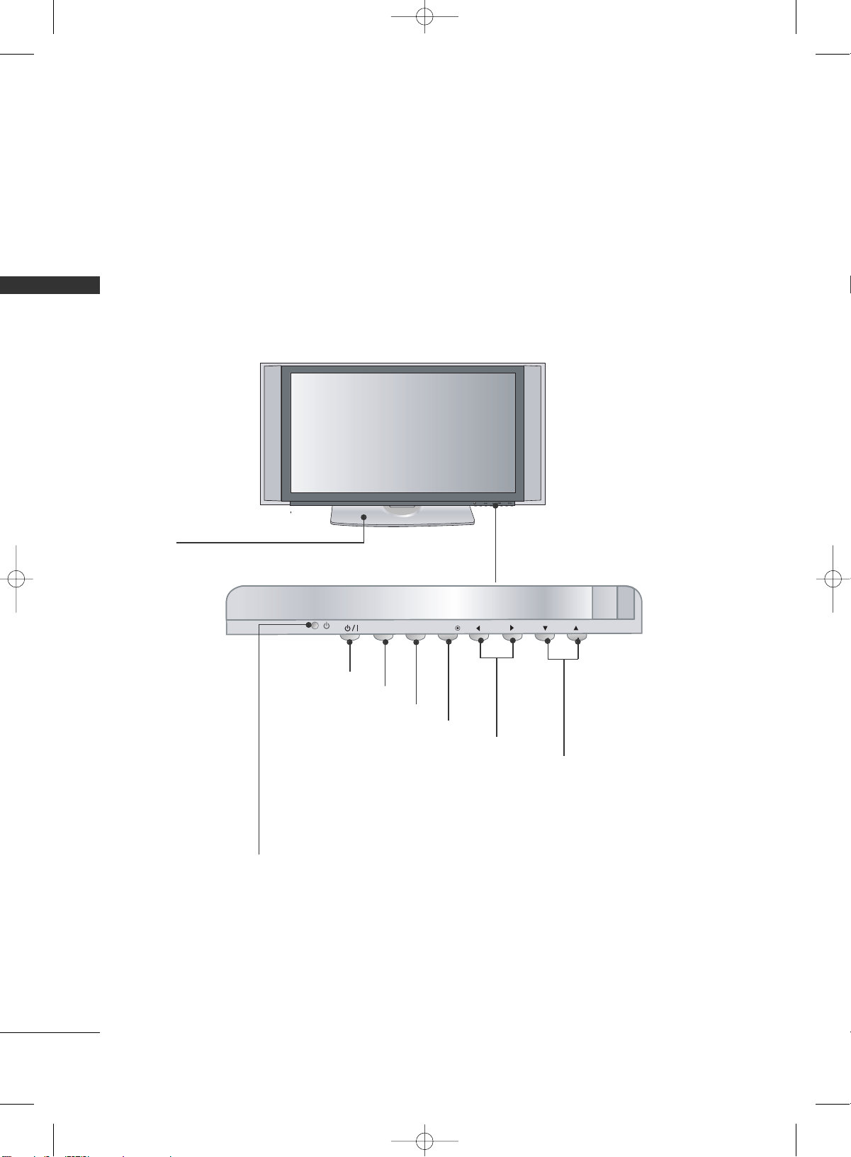
FRONT PANEL CONTROLS
PREPARATION
■
Here shown may be somewhat different from your TV.
CHCH
VOLOL
ENTERENTER
MENUMENU
INPUTINPUT
Remote Control Sensor
Power/Standby Indicator
Illuminates red when the TV is in standby mode.
Illuminates green when the TV is switched on.
CHANNEL Buttons
VOLUME Buttons
ENTER Button
MENU Button
INPUT Button
POWER Button
32/37/42LC5DC*,32/37/42LC50C*, 42LB5DC, 42LB50C
Tighten the two of these four screws and
the two Torx plus star head screws (provided as parts of the TV) to secure the TV.
Tighten the two Torx plus star head screws
with a star head driver bit (not provided
as parts of the TV).
x 2
x 2
x 4
Tighten the stand with the
four screws (provided as parts
of the TV).
or
MFL34797070en-1 4/16/09 2:14 PM Page 8

PREPARATION
9
32LX5DC*, 32LX50C*
CH
VOL
ENTER
INPUT
MENU
ON/OFF
VOLUME Buttons
Remote Control Sensor
Power/Standby
Indicator
Illuminates red when the
TV is in standby mode.
Illuminates green when
the TV is switched on.
CHANNEL Buttons
ENTER Button
ON/OFF Button
INPUT Button
MENU Button
MFL34797070en-1 4/16/09 2:14 PM Page 9
CH
VOL
ENTER
INPUT
MENU
ON/OFF
PREPARATION
10
PREPARATION
42PX8DC
CH
VOL
MENUINPUT
ENTER
INPUTINPUT
ENTERENTER
VOLUME Buttons
CHANNEL Buttons
ENTER Button
POWER Button
INPUT Button
MENU Button
Remote Control Sensor
Power/Standby Indicator
Illuminates red when the TV is in standby mode.
Illuminates green when the TV is switched on.
This TV’s stand is sold, separately.
MFL34797070en-1 4/16/09 2:14 PM Page 10
PREPARATION
11
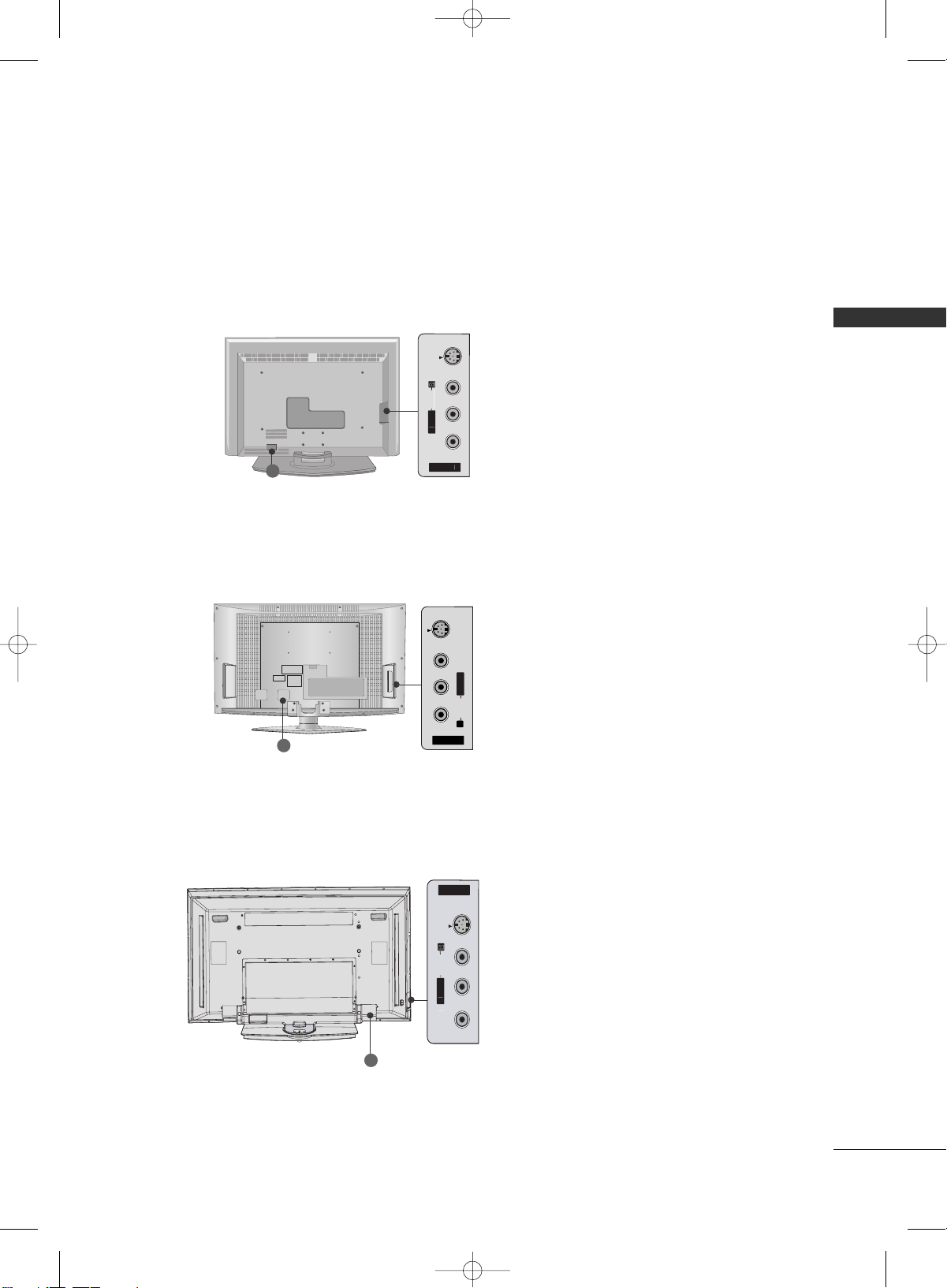
BACK PANEL INFORMATION
■
Here shown may be somewhat different from your TV.
O
O
S-VIDEO
S-VIDEO Input
Provides better picture quality than the
video input.
VIDEO Input
Connects the video signal from a video
device.
AUDIO Input
11
32/37/42LC5DC*,32/37/42LC50C*, 42LB5DC, 42LB50C
32LX5DC*, 32LX50C*
R
S-VIDEO Input
Provides better picture quality than the
video input.
VIDEO Input
Connects the video signal from a video
device.
AUDIO Input
AV IN 2
VIDEO
S-VIDEO
L/MONO
R
AUDIO
42PX8DC
S-VIDEO Input
Provides better picture quality than the
video input.
VIDEO Input
Connects the video signal from a video
device.
AUDIO Input
11
11
O
O
MFL34797070en-1 4/16/09 2:14 PM Page 11
N
IDE
AV IN 2
S-VIDEO
N
VIDE

PREPARATION
12
PREPARATION
HDMI/DVI IN , HDMI IN
Connect a HDMI (DVI) connection to either input.
DIGITAL AUDIO OUT
Connect digital audio from various types of equipment.
Note: In standby mode, these ports do not work.
M.P.I
RESET/UPDATE/REMOTE CONTROL OUT
SERVICE ONLY
RGB IN (PC)
Connect the output from a PC.
AUDIO IN (RGB, DVI)
Connect the audio from a PC or DTV.
SPEAKER OUT 8Ω
AV (Audio/Video) IN
Connect audio/video output from an external
device to these jacks.
S-VIDEO
Connect S-Video out from an S-VIDEO device.
COMPONENT IN
Connect a component video/audio device to these
jacks.
RJP INTERFACE
Power Cord Socket
For operation with AC power.
Caution: Never attempt to operate the TV on DC
power.
ANTENNA IN
Connect over-the air signals to this jack.
1
8
9
10
11
12
2
3
4
5
6
7
VIDEO
AUDIO
VIDEO
AUDIO
MONO
( )
S-VIDEO
REMOTE
CONTROL
OUT
RGB IN
AUDIO
IN
(RGB, DVI)
RESET
UPDATE
M.P.I.
)
RJP
INTERFACE
SERVICE ONLY
N
SPEAKER
OUT
8
AV IN 1
COMPONENT IN
L
O
OUT
(
)
ANTENNA INANTENNA IN
M.P.I.M.P.I.
6
1
5
2
3
4
7
8
9
10
12
13
13
■
Here shown may be somewhat different from your TV.
This part mainly use picture for the LCD TV models.
MFL34797070en-1 4/16/09 2:14 PM Page 12
DIGITA
AUDI
OPTICAL
HDMI/DVI I
1(DVI
PREPARATION
13
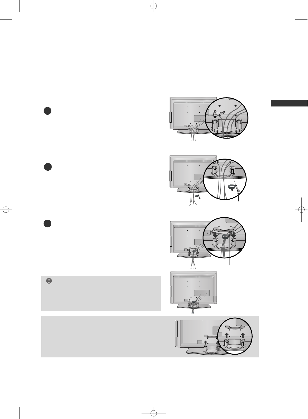
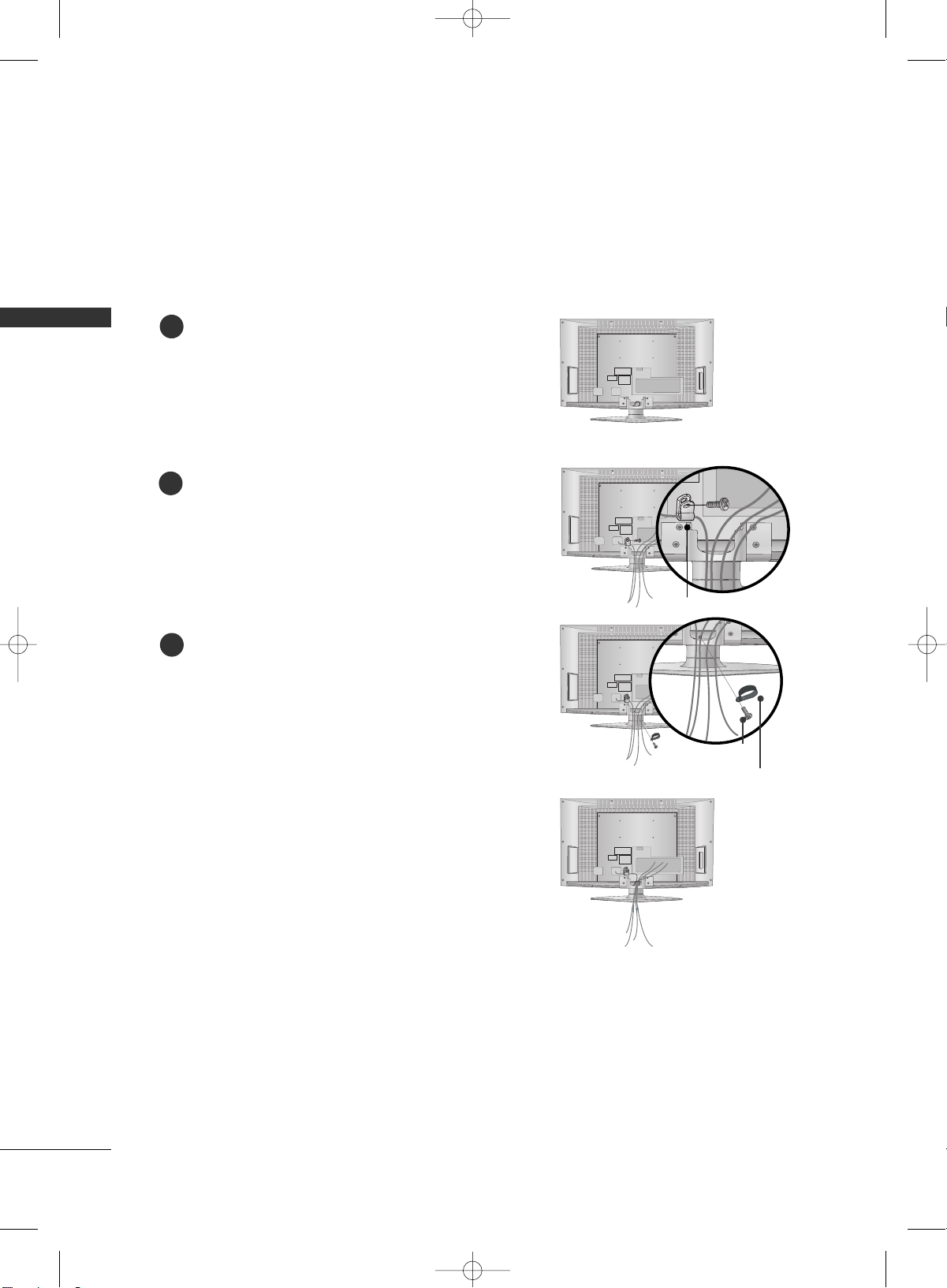
BACK COVER FOR WIRE ARRANGEMENT
Connect the cables as necessary.
To connect an additional equipment, see the EXTERNAL
EQUIPMENT SETUP section.
Secure the power cable with the PROTECTIVE
BRACKET and the screw as shown. It will help prevent
the power cable from being removed by accident.
Install the CABLE MANAGEMENT as shown.
How to remove the CABLE MANAGEMENT
GG
Hold the CABLE MANAGEMENT with both hands and
pull it backward.
CABLE MANAGEMENT
GG
Do not hold the CABLE MANAGEMENT when moving
the product.
- If the product is dropped, you may be injured or the
product may be damaged.
NOTE
1
3
Install the CABLE HOLDER as shown.
CABLE HOLDER
2
BOLT
■
Here shown may be somewhat different from your TV.
PROTECTIVE BRACKET
(This feature is not available for all models.)
MFL34797070en-1 4/16/09 2:14 PM Page 13
PREPARATION
14
BACK COVER FOR WIRE ARRANGEMENT
PREPARATION
■
Here shown may be somewhat different from your TV.
(This feature is not available for all models.)
Connect the cables as necessary.
To connect an additional equipment, see the EXTERNAL
EQUIPMENT SETUP section.
Secure the power cable with the PROTECTIVE
BRACKET and the screw as shown. It will help prevent
the power cable from being removed by accident.
2
Install the CABLE HOLDER as shown.
CABLE
HOLDER
3
BOLT
To separate the CABLE HOLDER, loosen the bolt
installed the set.
1
PROTECTIVE BRACKET
MFL34797070en-1 4/16/09 2:14 PM Page 14

PREPARATION
15
42PX8DC
Hold the CABLE MANAGEMENT with both
hands and pull it as shown.
Connect the cables as necessary.
To connect an additional equipment, see the
EXTERNAL EQUIPMENT SETUP section.
1
2
Install the CABLE MANAGEMENT as shown.
3
45
°
GG
Do not hold the CABLE MANAGEMENT CLIP
when moving the TV.
- If the TV is dropped, you may be injured or
the product may be broken.
NOTE
!
■
Here shown may be somewhat different from your TV.
MFL34797070en-1 4/16/09 2:14 PM Page 15

PREPARATION
16
PREPARATION
The TV can be conveniently swivelled on its stand 20°or 90° to the left or right to provide the optimum viewing angle.
SWIVEL STAND
20° (37LC5DC1, 42LC5DC,
42LC50C,
42PX8DC,
42LB5DC, 42LB50C
models)
90° (32LX5DC/S,
32LX50C/S,
32LC5DC/S,
32LC50C/S,
37LC5DC,
37LC50
models)
ATTACHING THE TV TO A WALL
We recommend that you set up the TV close to a wall so it cannot fall over if pushed backwards.
Additionally, we recommend that the TV be attached to a wall so it cannot be pulled in a forward direction,
potentially causing injury or damaging the product.
Caution: Please make sure that children don’t climb on or hang from the TV.
■
Insert the TV brackets (or eye-bolts) and bolts to tighten the product to the wall as shown in the picture.
*If your product has the bolts in the eye-bolts position before inserting the eye-bolts, loosen the bolts.
Secure the wall brackets with the bolts (not provided as parts of the product, must purchase separately) on
the wall. Match the height of the bracket that is mounted on the wall to the holes in the product.
Ensure the eye-bolts or brackets are tightened securely.
■
Use a sturdy rope (not provided as parts of the product, must purchase separately) to tie the product. It is safer to tie the rope so it
becomes horizontal between the wall and the product.
■
This feature is not available for all models.
MFL34797070en-1 4/16/09 2:14 PM Page 16

PREPARATION
17
ATTACHING THE TV TO A DESK
The TV must be attached to desk so it cannot be pulled in a forward/backward direction,
potentially causing injury or damaging the product.
*
SSccrreewwss -- MM55 xx LL ((ttaabbllee ddeepptthh ++ 88~11 00 mmmm))
ex) table depth-15mm: Bolts - M5 x 25
WARNING
GG
This apparatus must be securely attached to the floor/wall per installation
instructions.Tipping, shaking, or rocking the machine may cause injury/death.
4-Screws
(not provided as parts of the product)
Stand
Desk
32/37/42LC5DC*, 32/37/42LC50C*, 42LB5DC, 42LB50C
32LX5DC*, 32LX50C*
42PX8DC
4-Screws
(not provided as parts of the product)
Stand
Desk
2-Screws
(not provided as parts of the product)
Stand
Desk
MFL34797070en-1 4/16/09 2:14 PM Page 17
PREPARATION
18
PREPARATION
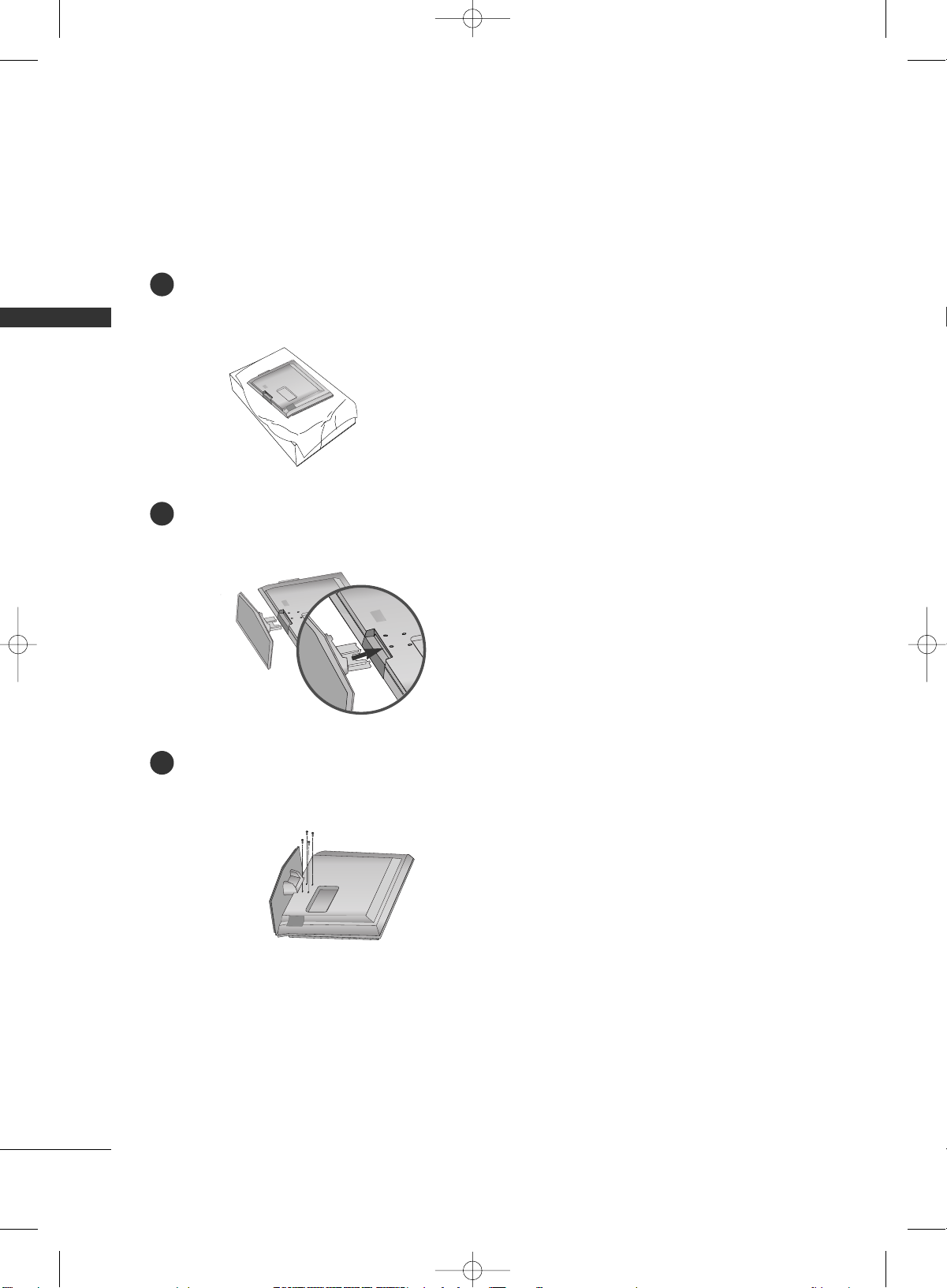
STAND INSTALLATION (Only 32/37LC5DC*,
32/37LC50*
models)
Carefully place the product screen side down on a cushioned surface that will protect product and screen from damage.
Assemble the product stand with the product as shown.
Securely install the 4 bolts provided.
1
2
3
MFL34797070en-1 4/16/09 2:14 PM Page 18

PREPARATION
19
VESA WALL MOUNTING
This product accepts a VESA-compliant mounting interface pad. (optional)
There 4 threaded holes are available for attaching the bracket.
GG
Screw length needed depends on the wall mount used. For further information, refer to the VESA
Wall Mounting Instruction Guide.
NOTE
Product Model
VESA
(A *B)
32LC5DC*, 32LC50C*,
32LX5DC*,
32LX50C*
32/37/42LC5DC*, 32/37/42LC50C*,
42LB5DC, 42LB50C
42PX8DC
200* 10 0
600* 400
600* 400
LCD TV
PLASMA TV
AA
BB
■
This feature is not available for all models.
For proper ventilation, allow a clearance of 4inches on each side from the wall.
■
Image shown may differ from your TV.
DESKTOP PEDESTAL INSTALLATION
GG
Ensure adequate ventilation by following the clearance recommendations.
CAUTION
4 inches
4 inches
4 inches
4 inches
■
This feature is not available for all models.
MFL34797070en-1 4/16/09 2:14 PM Page 19

PREPARATION
20
PREPARATION
ANTENNA OR CABLE CONNECTION
1. Antenna (Analog or Digital)
Wall Antenna Socket or Outdoor Antenna without a Cable Box
Connections.
For optimum picture quality, adjust antenna direction if needed.
2. Cable
Wall
Antenna
Socket
Outdoor
Antenna
(VHF, UHF)
Cable TV
Wall Jack
Multi-family Dwellings/Apartments
(Connect to wall antenna socket)
RF Coaxial Wire (75 ohm)
RF Coaxial Wire (75 ohm)
Single-family Dwellings /Houses
(Connect to wall jack for outdoor antenna)
Be careful not to bend the bronze wire
when connecting the antenna.
Copper Wire
ANTENNA IN
M.P.I.
ANTENNA IN
M.P.I.
ANTENNA IN
M.P.I.
GG
The TV will let you know when the analog, cable, and digital channel scans are complete.
NOTE
■
To improve the picture quality in a poor signal area, please purchase a signal amplifier and install properly.
■
If the antenna needs to be split for two TV’s, install a 2-Way Signal Splitter.
■
If the antenna is not installed properly, contact your dealer for assistance.
Antenna
UHF
Signal
Amplifier
VHF
MFL34797070en-1 4/16/09 2:14 PM Page 20

EXTERNAL EQUIPMENT SETUP
21
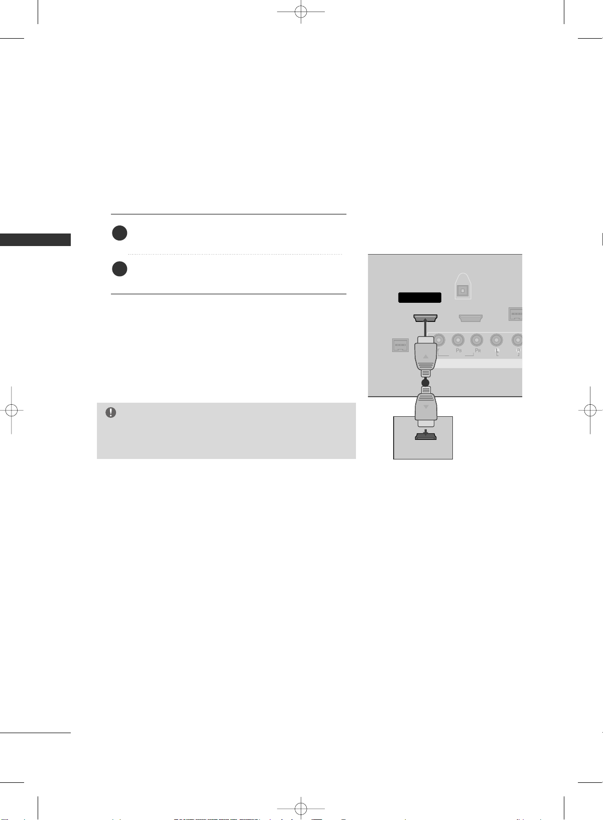
HD RECEIVER SETUP
EXTERNAL EQUIPMENT SETUP
This TV can receive Digital Over-the-air/Cable signals without an external digital set-top box. However, if you
do receive digital signals from a digital set-top box or other digital external device, refer to the figure as shown
below.
( )
S-VIDEO
M.P.I.
1(DVI)
2
HDMI/DVI IN
COMPONENT IN
DIGITAL
AUDIO
OUT
(OPTICAL)
VIDEO
AUDIO
Y L RPB PR
When connecting Component cable
1
2
1. How to connect
Connect the video outputs (Y, P
B, PR
)
of the digital set
top box to the
CCOOMM PP OONNEENNTT IINN VVIIDDEEOO
jacks on
the set. Match the jack colors
(Y = green, P
B = blue, and PR = red).
Connect the audio output of the digital set-top box to
the
CCOOMM PP OONNEENNTT IINN AAUUDD II OO
jacks on the set.
2
1
2. How to use
■
Turn on the digital set-top box.
(
Refer to the owner’s manual for the digital set-top box.
)
■
Select
CCoommpp oonnee nntt
input source with using the
IINNPPUUTT
button on the remote control.
Signal
480i
480p
720 p
10 8 0 i
10 8 0 p
Component
Yes
Yes
Yes
Yes
Yes
HDMI1/DVI,
HDMI2
No
Yes
Yes
Yes
Yes
■
To prevent the equipment damage, never plug in any power cords until you have finished connecting all equipment.
■
This part of external equipment setup mainly use picture for LCD TV models.
* 42LB5DC, 42LB50C model only
MFL34797070en-1 4/16/09 2:14 PM Page 21
EXTERNAL EQUIPMENT SETUP
22
EXTERNAL EQUIPMENT SETUP
When connecting HDMI cable
Connect the digital set-top box to
HHDDMMII//DDVVII IINN
11 ((DDVV II ))
or
22
jack on the set.
No separated audio connection is necessary.
HDMI supports both audio and video.
1. How to connect
2. How to use
■
Turn on the digital set-top box.
(
Refer to the owner’s manual for the digital set-top box.
)
■
Select
HHDDMMII11//DD VVII
or
HHDDMMII22
input source with using
the
IINNPPUUTT
button on the remote control.
2
1
VIDEO
AUDIO
( )
M.P.I
1(DVI)
RJP
INTERFACE
2
HDMI/DVI IN
COMPONENT IN
DIGITAL
AUDIO
OUT
(OPTICAL)
HDMI-DTV OUTPUT
1
GG
If the device does not support Auto HDMI, you need to set
the output resolution appropriately.
NOTE
MFL34797070en-1 4/16/09 2:14 PM Page 22
EXTERNAL EQUIPMENT SETUP
23
VIDEO
AUDIO
VIDEO
AUDIO
MONO
( )
S-VIDEO
REMOTE
CONTROL
OUT
RGB IN
AUDIO
IN
(RGB, DVI)
RESET
UPDATE
M.P.I.
1(DVI)
RJP
INTERFACE
2
SERVICE ONLY
HDMI/DVI IN
SPEAKER
OUT
8
AV IN 1
COMPONENT IN
DIGITAL
AUDIO
OUT
(OPTICAL)
( )
L R
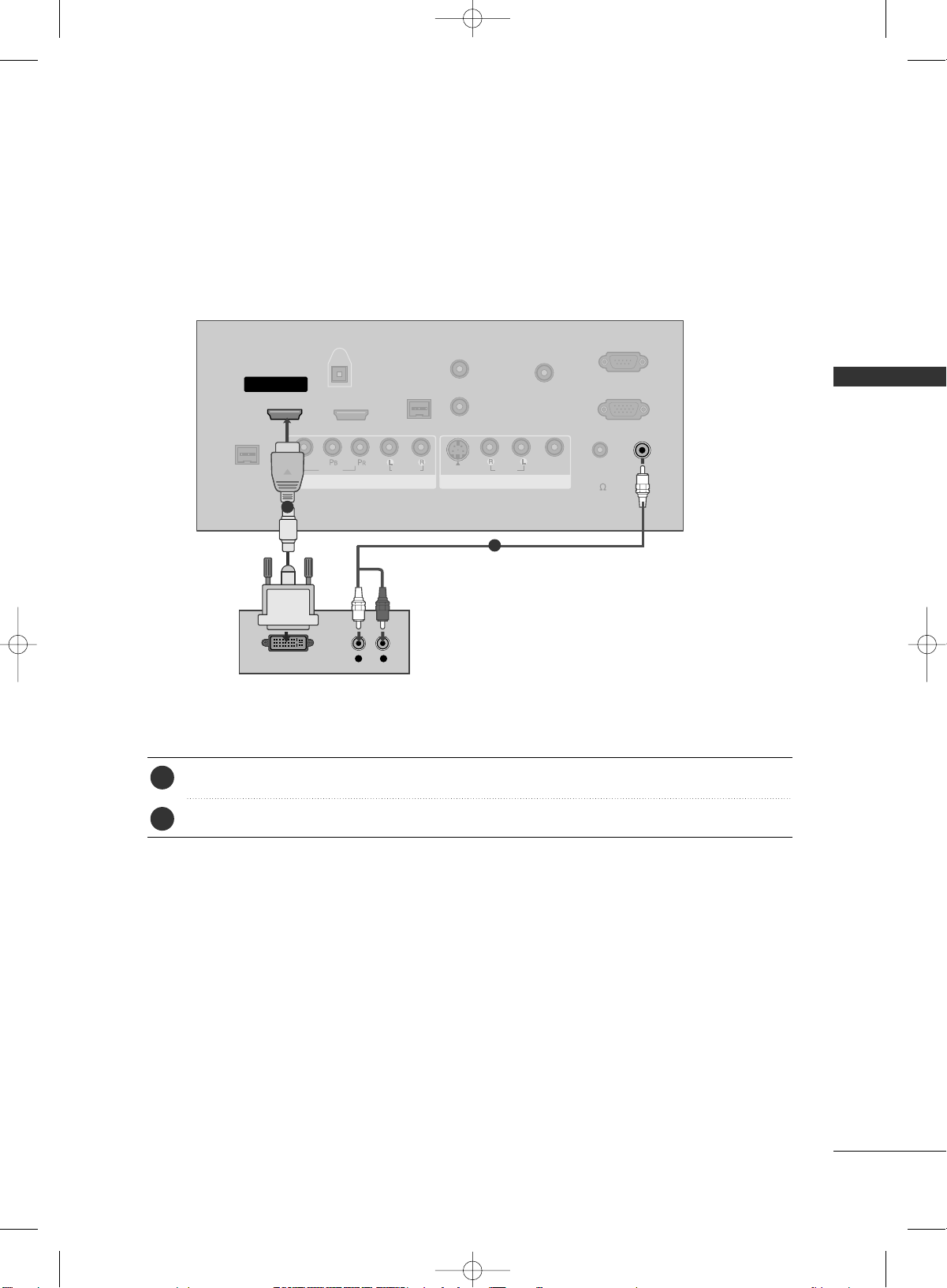
DVI-DTV OUTPUT
Connect the DVI output of the digital set-top box to the
HHDDMMII//DDVVII IINN 11((DDVVII))
or
22
jack on the set.
Connect the audio output of the digital set-top box to the
AAUUDDIIOO IINN ((RRGGBB,,DD VVII
))
jack on the set.
1. How to connect
■
Turn on the digital set-top box. (Refer to the owner’s manual for the digital set-top box.
)
■
Select
HHDDMMII11//DD VVII
or
HHDDMMII 22
input source with using the
IINNPPUUTT
button on the remote control.
2. How to use
2
1
1
2
When connecting HDMI to DVI cable
MFL34797070en-1 4/16/09 2:14 PM Page 23

EXTERNAL EQUIPMENT SETUP
24
EXTERNAL EQUIPMENT SETUP
DVD SETUP
When connecting Component cable
( )
S-VIDEO
M.P.I.
1(DVI)
2
HDMI/DVI IN
COMPONENT IN
DIGITAL
AUDIO
OUT
(OPTICAL)
VIDEO
AUDIO
Y L RPB PR
Component Input ports
To get better picture quality, connect a DVD player to the component input ports as shown below.
Component ports on the TV
YPB PR
Video output ports
on DVD player
Y
Y
Y
Y
P
B
B-Y
Cb
Pb
P
R
R-Y
Cr
Pr
Connect the video outputs (Y, PB
, PR
)
of the DVD to
the
CCOOMM PP OONNEENNTT IINN VVIIDDEEOO
jacks on the set.
Match the jack colors
(
Y = green, P
B = blue, and PR = red
)
.
Connect the audio outputs of the DVD to the
CCOOMM PP OONNEENNTT IINN AAUUDD IIOO
jacks on the set.
1. How to connect
2. How to use
■
Turn on the DVD player, insert a DVD.
■
Select
CCoommpp oonnee nntt
input source with using the
IINNPPUUTT
button on the remote control.
■
Refer to the DVD player's manual for operating instructions.
2
1
1 2
MFL34797070en-1 4/16/09 2:14 PM Page 24
EXTERNAL EQUIPMENT SETUP
25
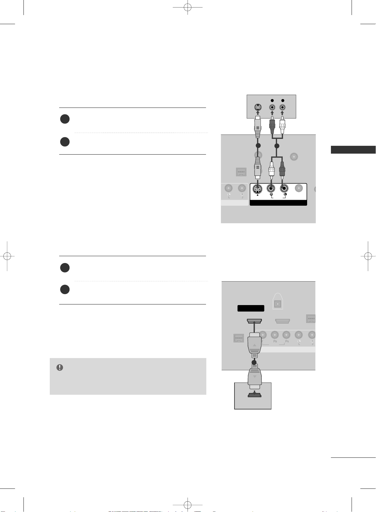
When connecting with an S-Video cable
AUDIO
REMOTE
CONTROL
OUT
RESET
UPDATE
M.P.I.
S
SPEA
O
AV IN 1
( )
AUDIO
MONO
( )
S-VIDEO
VIDEO
L R
S-VIDEO
AUDIO
1
2
VIDEO
AUDIO
( )
M.P.I
1(DVI)
RJP
INTERFACE
2
HDMI/DVI IN
COMPONENT IN
DIGITAL
AUDIO
OUT
(OPTICAL)
HDMI-DVD OUTPUT
1
Connect the S-VIDEO output of the DVD to the
SS --VV II DD EEOO
input on the set.
Connect the audio outputs of the DVD to the
AAUUDD II OO
input jacks on the set.
1. How to connect
2. How to use
■
Turn on the DVD player, insert a DVD.
■
Select
AAVV11
input source with using the
IINNPPUUTT
button on
the remote control.
■
If connected to
AAVV II NN22
, select
AAVV 22
input source.
■
Refer to the DVD player's manual for operating instructions.
When connecting HDMI cable
Connect the HDMI output of the DVD to the
HHDDMMII//DDVVII IINN 11((DDVV II))
or 22jack on the set.
No separated audio connection is necessary.
HDMI supports both audio and video.
1. How to connect
2. How to use
■
Select
HHDDMMII11//DD VVII
or
HHDDMMII 22
input source with using
the
IINNPPUUTT
button on the remote control.
■
Refer to the DVD player's manual for operating instructions.
2
1
2
1
GG
If the device does not support Auto HDMI, you need to
set the output resolution appropriately.
NOTE
MFL34797070en-1 4/16/09 2:14 PM Page 25

EXTERNAL EQUIPMENT SETUP
26
EXTERNAL EQUIPMENT SETUP
VCR SETUP
When connecting with an antenna
■
To avoid picture noise (interference), leave an adequate distance between the VCR and TV.
■
Use the ISM feature in the Option menu to avoid having a fixed image remain on the screen for a long period
of time.
(Only
Plasma TV model). If the 4:3 picture format is used; the fixed images on the sides of the screen
may remain visible on the screen. This phenomenon is common to all manufactures and in consequence the
manufactures warranty does not cover the product bearing this phenomenon.
ANTENNA IN
M.P.I.
L R
S-VIDEO VIDEO
OUTPUT
SWITCH
ANT IN
ANT OUT
Wall Jack
Antenna
1
2
Connect the RF antenna out socket of the VCR to the
AAnntt ee nnnnaa
socket on the set.
Connect the antenna cable to the RF antenna in socket of the VCR.
1. How to connect
■
Set VCR output switch to 3 or 4 and then tune TV to the same channel number.
■
Insert a video tape into the VCR and press PLAY on the VCR. (Refer to the VCR owner’s manual.
)
2. How to use
2
1
MFL34797070en-1 4/16/09 2:14 PM Page 26
 Loading...