

Page 1

CHASSIS : MV-025A
MODEL : KE-14P21B/BX/S/SX
MODEL
CONTENT
Deck Mechanism Disassembly..................4-1
Mechanism Adjustment ............................4-15
Maintenance/Inspection Procedure
......4-22
Mechanism Troubleshooting Guide
.......4-26
Exploded Views .............................................4-31
SECTION 4 MECHANISM PART
TVCR
SERVICE MANUAL
Page 2
4-1
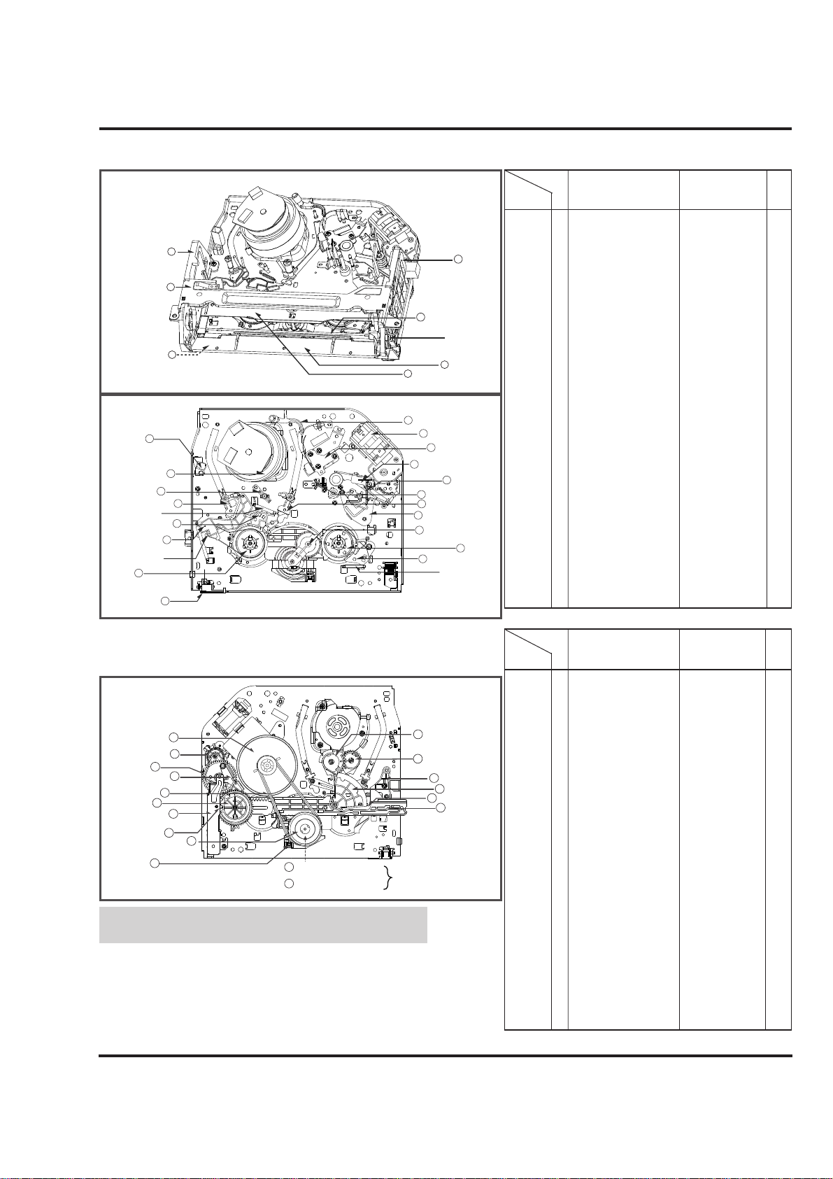
DECK MECHANISM PARTS LOCATIONS(FOR NORMAL MODELS)
• Top View
• Bottom View
Motor Capstan 23
Gear Connector 32
Gear Cam 31
Brake Assembly 29
Capstan
Belt Capstan 22
Gear Drive 30
Guide Rack F/L 27
Gear Rack F/L 28
Clutch Assembly D33-K
24
Lever F/R 25
26 Gear Assembly H-Up/D-K
Option
38 Gear Assembly P3
39 Gear Assembly P2
35 Base Tension
34 Gear Sector
37 Lever Tension
36 Plate Slider
(For High Rewind Models)
26 Gear Assembly Up/D-K
(For Normal Models)
NOTE : When reassembly perform the
procedure in the reverse order.
1) When reassembling, confirm Mechanism and Mode
Switch Alignment Position (Pefer to Page 4-14)
2) When disassembling, the Parts for Starting No. Should
be removed first.
1 Drum Assembly 3 Screws , Cap FPC A-1
2 Plate Assembly Top Two Hooks A-2
2 3 Holder Assembly CST Chassis Hole A-2
4 Guide CST 2 Hooks A-2
2,3,4 5 Bracket Side (L) 1 Screw A-2
2,3,4 6 Bracket Assembly Door 1 Screw A-2
2,3,4,5,6 7 Arm Assembly F/L Chassis Hole A-2
2,3,4,5 8 Lever Assembly S/W Chassis Hole A-2
9 Arm Assembly Cleaner Chassis Embossing A-3
10 Head F/E 2 Hooks A-3
11 Base Assembly A/C Head 1 Screw A-3
12 Brake Assembly S Chassis Hole A-4
2,3 13 Brake Assembly T Chassis Hole A-4
2,3,12, 14 Arm Assembly T ension Chassis Hole A-4
2,3,12,14 15 Reel S Chassis Shaft A-4
2,3,13 16 Reel T Chassis Shaft A-4
17 Support CST Chassis Embossing A-5
18 Base Assembly P4 Chassis Embossing A-5
19 Opener Lid Chassis Embossing A-5
19 20 Arm Assembly T/Up Chassis Embossing A-5
19 21 Arm Assembly Pinch Chassis Shaft A-5
Starting
No.
Pracedure
Part
Fixing Type
Fig-
ure
22 Belt Capstan A-6
22 23 Motor Capstan 3 Screws A-6
24 Clutch Assembly D33-K 1 Washer A-6
22,24 25 Lever F/R 1 Hook A-6
22,24 26 Gear H-Up/D-K 2 Washers A-6
27 Guide Rack F/L 1Screw A-7
27 28 Gear Rack F/L A-7
27, 28 29 Brake Assembly Capstan Chassis Shaft A-7
27, 28 30 Gear Drive 1 Washer A-8
27, 28, 29 31 Gear Cam Chassis Shaft A-8
27, 28, 29, 30
32 Gear Connector Chassis Shaft A-8
33 Bracket Assembly L/D Motor 3 Hooks A-8
34 Gear Sector 3 Washers A-9
35 BaseT ension 1 Screw A-9
22, 24, 25,
36 Plate Slider Chassis Shaft A-9
27, 28, 30, 34
35
22, 24, 25,
27, 28, 30, 34
37 Lever T ension Chassis Hole A-9
35
34 38 Gear Assembly P3 2 Hooks A-10
34, 38 39 Gear Assembly P2 2 Hooks A-10
34, 38, 39 40 Base Assembly P3 Chassis Hole A-10
34, 38, 39, 40
41 Base Assembly P2 Chassis Hole A-10
1, 2 42 Arm Assembly Idler 1 Hook A-10
Starting
No.
Pracedure
Part
Fixing Type
Fig-
ure
Bracket Side 'L' 5
Plate Assembly 2
Top
Lever Assembly 8
S/W
6 Bracket
Assembly Door
7 Arm Assembly F/L
Opener Door
4 Guide CST
3 Holder Assembly CST
9 Arm Assembly Cleaner
Head F/E 10
Drum Assembly 1
Support CST 17
Base Assembly P2 41
Brake Spring S
Brake Assembly S 12
Arm Assembly 14
Tension
Band Assembly
Tension
Reel S 15
Lever
Assembly S/W 8
33 Bracket Assembly
21 Arm Assembly Pinch
L/D Motor
11 Base Assembly
A/C Head
19 Opener Lid
18 Base Assembly P4
40 Base Assembly P3
20 Arm Assembly T/Up
42 Arm Assembly ldler
16 Reel T
13 Brake Assembly T
Brake Spring T
Page 3
4-2
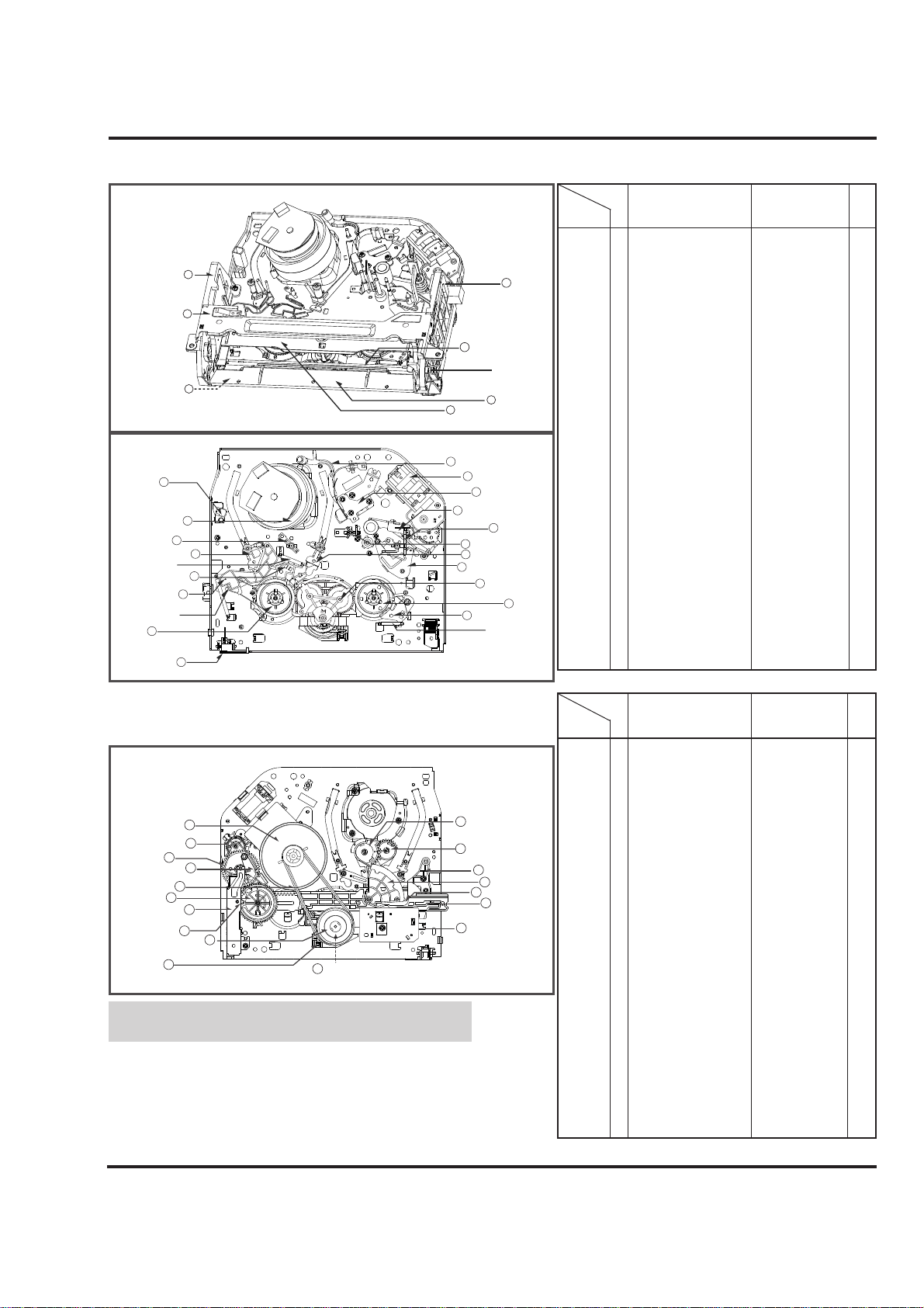
DECK MECHANISM PARTS LOCATIONS(FOR JOG SHUTTLE MODELS)
• Top View
• Bottom View
NOTE : When reassembly perform the
procedure in the reverse order.
1) When reassembling, confirm Mechanism and Mode
Switch Alignment Position (Pefer to Page 4-14)
2) When disassembling, the Parts for Starting No. Should
be removed first.
1 Drum Assembly 3 Screws , Cap FPC A-1
2 Plate Assembly Top Two Hooks A-2
2 3 Holder Assembly CST Chassis Hole A-2
4 Guide CST 2 Hooks A-2
2,3,4 5 Bracket Side (L) 1 Screw A-2
2,3,4 6 Bracket Assembly Door 1 Screw A-2
2,3,4,5,6 7 Arm Assembly F/L Chassis Hole A-2
2,3,4,5 8 Lever Assembly S/W Chassis Hole A-2
9 Arm Assembly Cleaner Chassis Embossing A-3
10 Head F/E 2 Hooks A-3
11 Base Assembly A/C Head 1 Screw A-3
12 Brake Assembly S Chassis Hole A-4
2,3 13 Brake Assembly T Chassis Hole A-4
2,3,12, 14 Arm Assembly Tension Chassis Hole A-4
2,3,12,14 15 Reel S Chassis Shaft A-4
2,3,13 16 Reel T Chassis Shaft A-4
17 Support CST Chassis Embossing A-5
18 Base Assembly P4 Chassis Embossing A-5
19 Opener Lid Chassis Embossing A-5
19 20 Arm Assembly T/Up Chassis Embossing A-5
19 21 Arm Assembly Pinch Chassis Shaft A-5
Starting
No.
Pracedure
Part
Fixing Type
Fig-
ure
22 Belt Capstan A-6
22 23 Motor Capstan 3 Screws A-6
24 Clutch Assembly D33-K 1 Washer A-6
22,24 25 Lever F/R 1 Hook A-6
22,24 26 Gear H-Up/D-K 2 Washers A-6
27 Bracket Assembly Jog 1 Screw A-7
28 Guide Rack F/L 1Screw A-7
28 29 Gear Rack F/L A-7
28, 29 30 Brake Assembly Capstan Chassis Shaft A-7
28, 29 31 Gear Drive 1 Washer A-8
28, 29, 30 32 Gear Cam Chassis Shaft A-8
28, 29, 30, 31
33 Gear Connector Chassis Shaft A-8
34 Bracket Assembly L/D Motor 3 Hooks A-8
35 Gear Sector 3 Washers A-9
36 BaseT ension 1 Screw A-9
22, 24, 25, 27
37 Plate Slider Chassis Shaft A-9
28, 29, 31, 35
36
22, 24, 25, 27
28, 29, 31, 35
38 Lever T ension Chassis Hole A-9
36
35 39 Gear Assembly P3 2 Hooks A-10
35, 39 40 Gear Assembly P2 2 Hooks A-10
35, 39, 40 41 Base Assembly P3 Chassis Hole A-10
35, 39, 40, 41
42 Base Assembly P2 Chassis Hole A-10
1, 2 43 Arm Assembly Idler Jog 1 Hook A-10
Starting
No.
Pracedure
Part
Fixing Type
Fig-
ure
Bracket Side 'L' 5
Plate Assembly 2
Top
Lever Assembly 8
S/W
6 Bracket
Assembly Door
7 Arm Assembly F/L
Opener Door
4 Guide CST
3 Holder Assembly CST
34 Bracket Assembly
L/D Motor
11 Base Assembly
A/C Head
19 Opener Lid
18 Base Assembly P4
41 Base Assembly P3
43 Arm Assembly
ldler Jog
16 Reel T
13 Brake Assembly T
Brake Spring T
Head F/E 10
Drum Assembly 1
Support CST 17
Base Assembly P2 42
Brake Spring S
Brake Assembly S 12
Arm Assembly 14
Tension
Band Assembly
Tension
Reel S 15
Lever
Assembly S/W 8
9 Arm Assembly Cleaner
21 Arm Assembly Pinch
20 Arm Assembly T/Up
39 Gear Assembly P3
40 Gear Assembly P2
36 Base Tension
35 Gear Sector
38 Lever Tension
37 Plate Slider
27 Bracket Assembly
Jog
Motor Capstan 23
Gear Connector 33
Gear Cam 32
Brake Assembly 30
Capstan
Belt Capstan 22
Gear Drive 31
Guide Rack F/L 28
Gear Rack F/L 29
Clutch Assembly D33-K
Lever F/R 25
24
26 Gear H-Up/D-K
Page 4
4-3
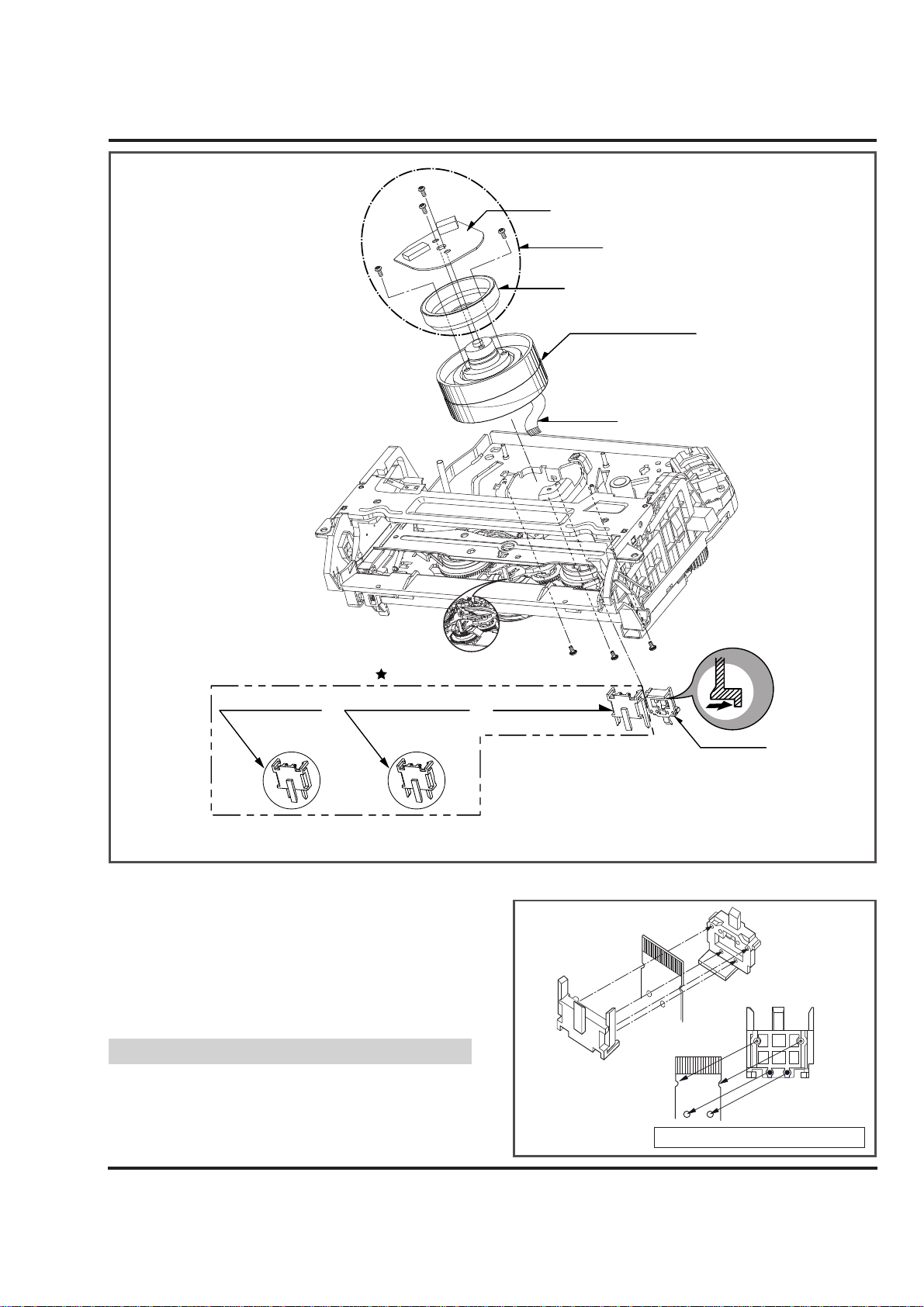
DECK MECHANISM DISASSEMBLY
(S2)
1. Drum Assembly (Fig. A-1-1)
1) Unhook the (H1) on the back side of the Chassis and
separate the Cap FPC.
2) Remove three Screws (S1) and lift up the Drum
Assembly.
3) Remove two Screws (S2) and Separate the Stator of
Drum Motor.
4) Remove two Screws (S3) and Separate the Rotor of
Drum Motor from the Drum Sub Assembly.
(1) When reassembling Cap FPC, two Holes of Drum FPC
are inserted to the two Bosses of Holder FPC correctly.
(Refer to Fig. B-1)
Fig. A-1
NOTE
(Fig. A-1-1)
(Fig. A-1-1)
(Fig. B-1)
Holder FPC
Drum FPC
Cap FPC
Figure in the opposite direction
(S3)
(S2)
Stator
(S3)
Drum Motor
Rotor
Drum Sub Assembly
Drum FPC
Holder FPC
(only for 2HD Models) (only for 4HD-Mono Models) (only for 4HD-Hi-Fi Models)
or Holder FPC or Holder FPC
(For Jog Shuttle Models)
Optional Parts
(S1)
(S1)
(S1)
H1
Cap FPC
Page 5
4-4
DECK MECHANISM DISASSEMBLY
H1
Fig. A-2
(Fig. A-2-1)
(Fig. A-2-2)
(Fig. A-2-6)
(Fig. A-2-7)
(Fig. A-2-5)
(Fig. A-2-3)
(Fig. A-2-4)
(A)
Plate Assembly Top
Arm Assembly F/L
H2
(B)
Holder Assembly CST
Lever Stopper(R)
Bracket Side (L)
H3
(H5)
(S4)
Guide CST
Groove
Lever Assembly S/W
(For Jog Shuttle Models)
Arm F/L
(S4)
Gear Rack F/L Groove
Bracket
Assembly Door
H4
Page 6
4-5
DECK MECHANISM DISASSEMBLY
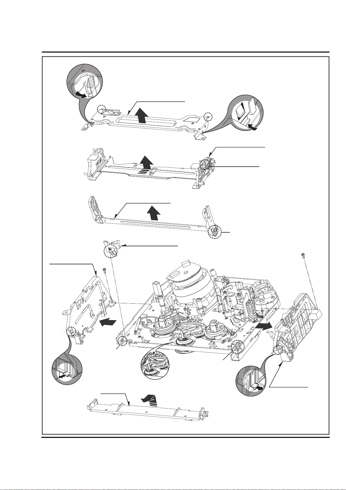
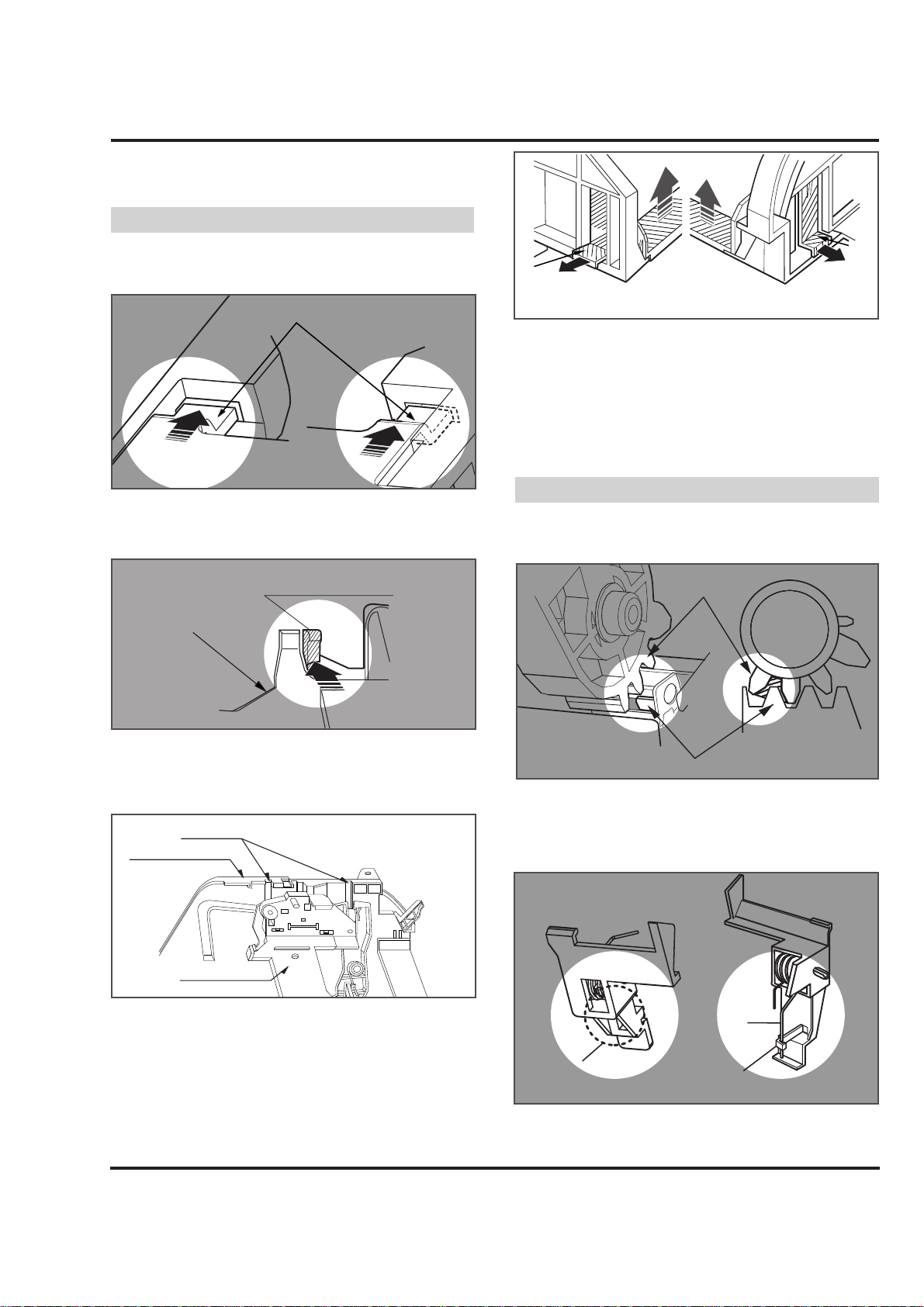
2. Plate Assembly Top (Fig. A-2-1)
1) Unhook the (H1) and separate the Left Side.
2) Unhook the (H2) and lift up the Plate Assembly Top.
(1) When reassembling, confirm (A),(B) Part of the Plate
Assembly Top is inserted to the (L),(R) Grooves of the
Bracket Side(L) and Bracket Assembly Door.
3. Holder Assembly CST (Fig.A-2-2)
1) Push the Lever Stopper (R) in the direction of the arrows
(A) and move the Holder Assembly CST.
2) Push the Bracket Assembly Door to the right and lift up
the Holder Assembly CSTalong the Guide Groove of the
Bracket Assembly Door.
4. Guide CST (Fig.A-2-3)
1) Unhook(H3) in the direction of the arrow and separate
the left side.
2) Unhook (H4) as above No.1) and disassemble the Guide
CST in the direction of the arrow.
5. Bracket Side(L) (Fig. A-2-4)/
Bracket Assembly Door (Fig.A-2-5)
1) Remove the Screw (S4) and disassemble the Bracket
Side(L) in the front.
2) Remove the Screw (S4) and disassemble the Bracket
Assembly Door in the front.
6. Arm Assembly F/L (Fig. A-2-6)
1) Push the Arm Assembly F/L to the left and lift up it.
(1) When reassembling, confirm that the Gear(A) of the Arm
F/L and the Gear(B) of the Gear Rack F/Lare assembled
as below.
7. Lever Assembly S/W (Fig. A-2-7)
1) Hook the Spring Lever S/W on (H5).
2) Lift up the left side of the Lever S/W from the Groove(A)
of the Chassis.
NOTE
Plate Assembly Top
Bracket Side (L)
Bracket Assembly Door
Lever Stopper (R)
Holder Assembly CST
(A)
Bracket Side (L)
Bracket Assembly Door
(H3)
(H4)
NOTE
Gear (B)
Gear (A)
(H5)
Spring
Lever S/W
(H5)
(L)
(A)
(R)
(B)
Guide Groove
Bracket Assembly Door
Holer Assembly CST
Page 7
4-6
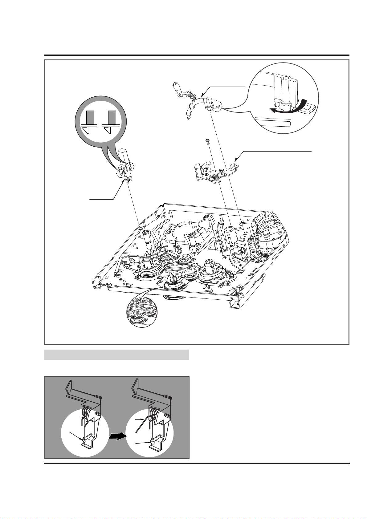
(1) Place the Spring Lever S/W of the above (No.1) as
original position.
8. Arm Assembly Cleaner(Fig. A-3-1)
1) Break away the (A) part shown above Fig. A-3-1 from the
Embossing of the Chassis in the clockwise direction and
lift up the Arm Assembly Cleaner.
9. Head F/E (Fig. A-3-2)
1) Unhook the two Hooks (H1) on the back side of the
Chassis and lift up the Head F/E.
10. Base Assembly A/C Head (Fig. A-3-3)
1) Remove the Screw (S5) and lift up the Base Assembly
A/C Head.
NOTE
DECK MECHANISM DISASSEMBLY
Arm Assembly
Fig. A-3
(Fig. A-3-1)
(Fig. A-3-3)
(Fig. A-3-2)
Spring
Lever S/W
(H5)
(H5)
Cleaner
( H1)
Head F/E
(A)
(S5)
Base Assembly A/C Head
(For Jog Shuttle Models)
Page 8
4-7
DECK MECHANISM DISASSEMBLY
Arm Assembly
Fig. A-4
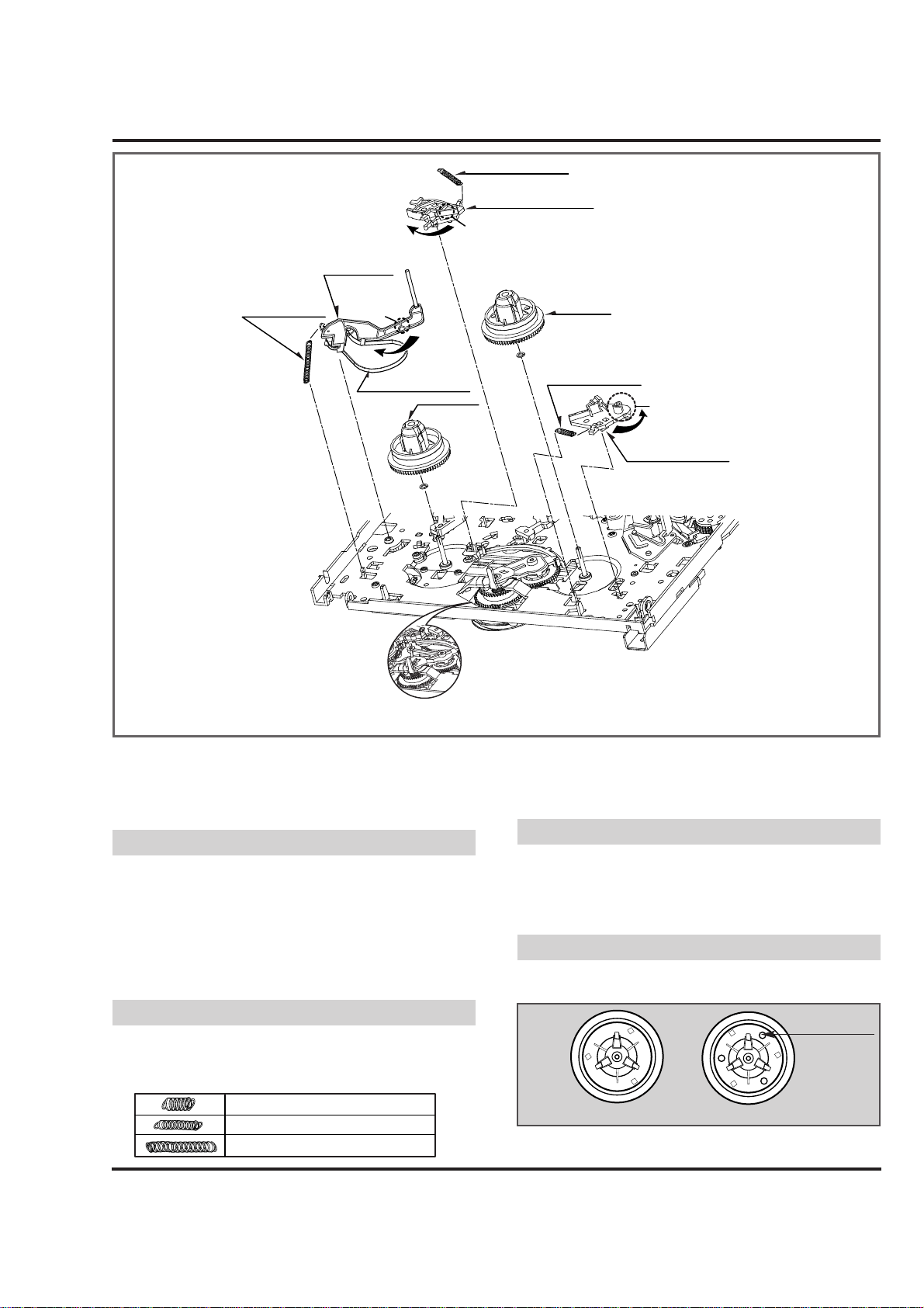
11. Brake Assembly S (Fig. A-4-1)
1) Remove the Spring S Brake.
2) Hold the (A) part shown above Fig. A-4-1 and turn to the
clockwise direction, and then lift up the Brake Assembly S.
(1) When reassembling, be careful not to change the Spring
with below No.12.(Refer to Fig. B-2).
12. Brake Assembly T (Fig. A-4-2)
1) Remove the Spring T Brake.
2) Hold the (B) part shown above Fig. A-4-2 and turn to the
counterclockwise direction, and then lift up the Brake
Assembly T.
(1) When reassembling, be careful not to change the Spring
with above No.11.(Refer to Fig. B-2).
13. Arm Assembly Tension (Fig. A-4-3)
1) Remove the Spring Tension.
2) Hold the (C) part shown above Fig. A-4-3 and turn to the clockwise direction, and then lift up the Arm Assembly Tension.
(1) When reassembling, be careful not to change the Spring
with above No.11,12.(Refer to Fig. B-2).
14. Reel S (Fig. A-4-4) & Reel T (Fig. A-4-5)
1) Lift up the Reel S and Reel T.
(1) When reassembling, be careful not to change the Reel S
and Reel T each other.
(2) Confirm two Slide Washers under the Reel S and Reel T.
NOTE
NOTE
(Difference for Springs)
Color (Black)
Three Holes
Reel S
Reel T
(Fig. B-2)
NOTE
NOTE
(Fig. A-4-1)
(Fig. A-4-5)
(Fig. A-4-3)
(Fig. A-4-4)
(Fig. A-4-2)
Tension
Spring S Brake
Brake Assembly S
(A)
Spring Tension
(C)
Band
Assembly
Tension
Reel S
(For Jog Shuttle Models)
Reel T
Spring T Brake
B
Brake Assembly T
Spring T Brake
Spring S Brake
Spring Tension
Page 9
4-8
DECK MECHANISM DISASSEMBLY
Fig. A-5
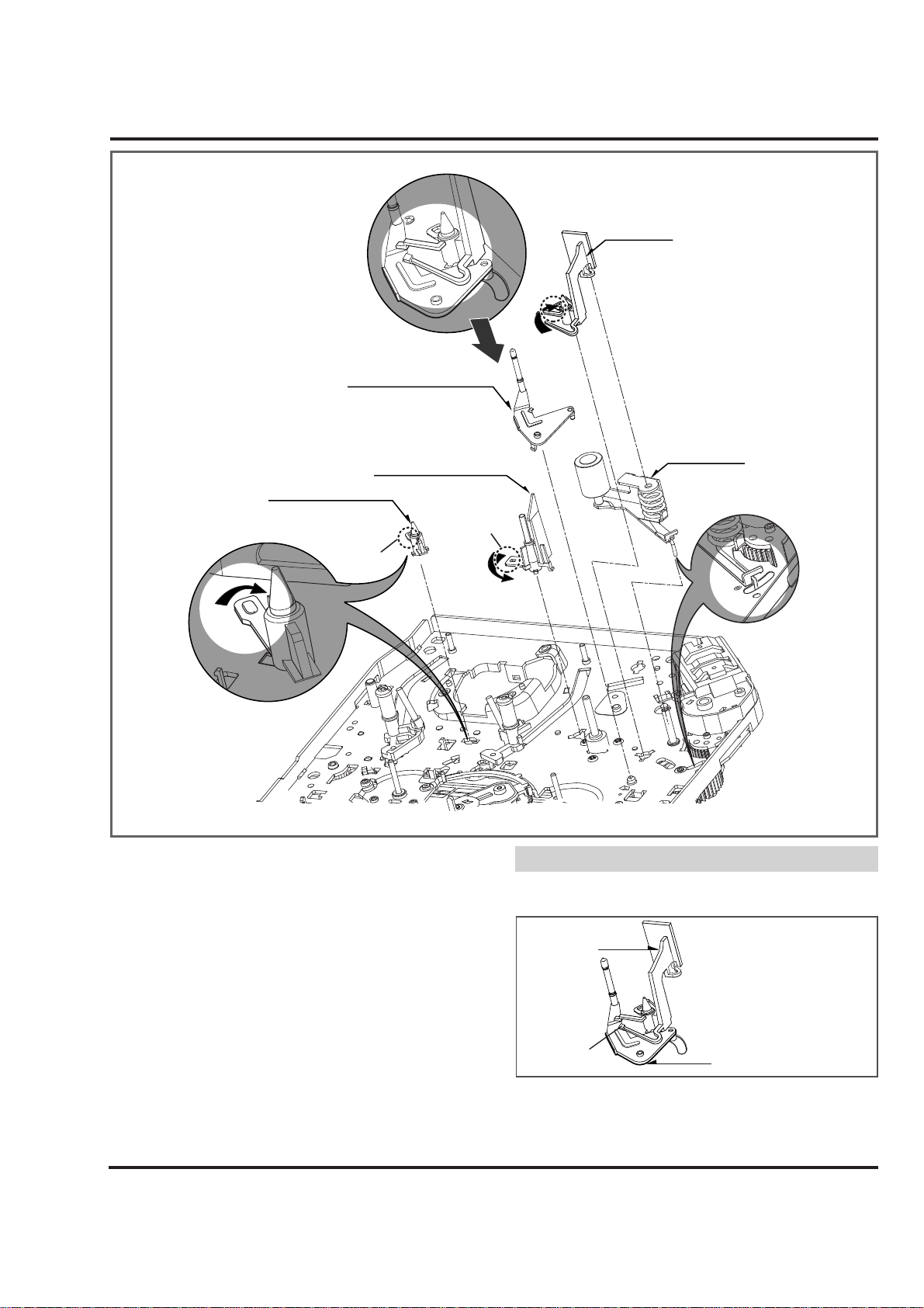
15. Support CST (Fig. A-5-1)
1) Break away the (A) part shown above Fig. A-5-1 from the
Embossing of the Chassis in the clockwise direction, and
lift up the Support CST.
16. Base Assembly P4 (Fig. A-5-2)
1) Break away the (B) part shown above Fig. A-5-2 from the
Embossing of the Chassis in the counterclockwise direction and lift up the Base Assembly P4.
17. Opener Lid (Fig. A-5-3)
1) Break away the (C) Part of the Opener Lid from the
Embossing of the Chassis in the Clockwise direction and
lift up the Opener Lid.
18. Arm Assembly T/up (Fig. A-5-4)
1) Just lift up the Arm Assembly T/UP.
(1) When reassembling, confirm the opener lid is placed on
the Hook(H1) of the Arm Assembly T/UP as below figure.
19. Arm Assembly Pinch (Fig. A-5-5)
1) Lift up the Arm Assembly Pinch.
NOTE
Opener Lid
Arm Assembly T/up
(Fig. A-5-3)
(Fig. A-5-4)
(Fig. A-5-1)
(Fig. A-5-2)
(Fig. A-5-5)
Arm Assembly T/up
Base Assembly P4
Support CST
(A)
(D)
Opener Lid
(C)
Arm
Assembly
Pinch
(B)
(H1)
Page 10
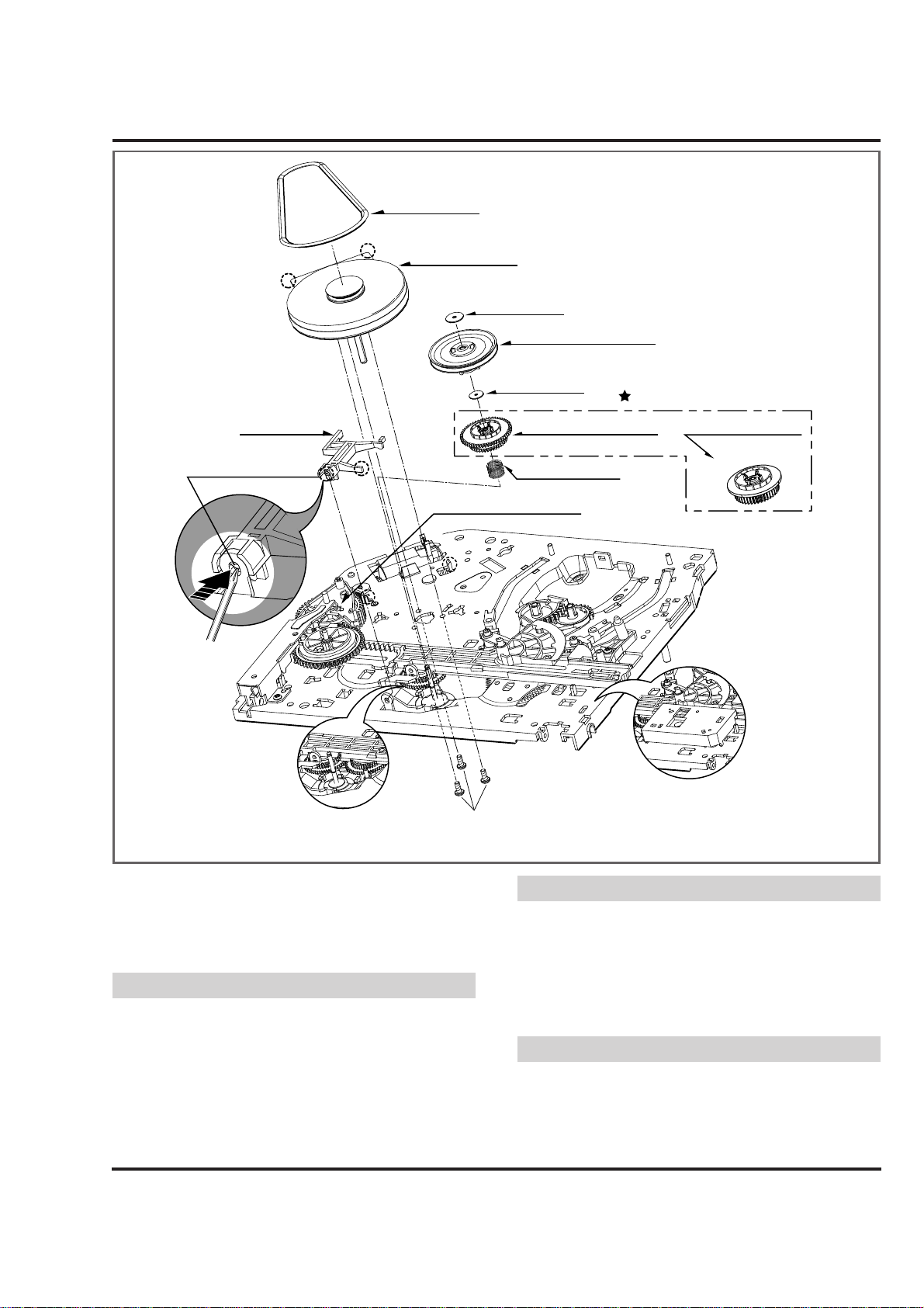
4-9
DECK MECHANISM DISASSEMBLY
Belt Capstan
Fig. A-6
20. Belt Capstan (Fig. A-6-1)/
Motor Capstan (Fig. A-6-2)
1) Remove the Belt Capstan.
2) Remove three Screws(S6) on the back side of the
Chassis and lift up the Motor Capstan.
(1) When reassembling, Confirm the (A), (B) parts of Motor
Capstan is located to the (A'), (B') of the Chassis.
21. Clutch Assembly D33-K (Fig. A-6-3)
1) Remove the Washer(W1) and lift up the Clutch Assembly
D33-K.
22. Lever F/R (Fig. A-6-4)
1) Unhook the (H1) shown above Fig. A-6-4 and lift up the
Lever F/R.
(1) When reassembling, move the (C) part of the Lever F/R up
and down, then confirm if it is returned to original position.
23. Gear H-Up/D-K or Gear Up/D-K
(Fig. A-6-5)
1) Remove the Washer(W2) and lift up the Gear H-up/D-K.
2) Remove the Spring Up/D.
(1) Gear H-Up/D-K is for Hi-Rewind Models.
(2) Gear Up/D-K is for Normal Models except Hi-Rewind Models.
NOTE
NOTE
(Fig. A-6-1)
(Fig. A-6-2)
(Fig. A-6-3)
(Fig. A-6-5)
(Fig. A-6-4)
NOTE
(B)
(A)
Lever F/R
Hook(H1)
(C)
( A')
Motor Capstan
Washer(W1)
Clutch Assembly D33-K
Washer(W2 )
(For Hi-Rewind Models) (For Normal Models)
Spring Up/D
Brake Assembly Capstan
(For 4HD Models)
(B ')
Optional Parts
Gear H-Up/D-K
or Gear Up/D-K
(For Jog Shuttle Models)
(For Jog Shuttle Models)
(S6)
Page 11
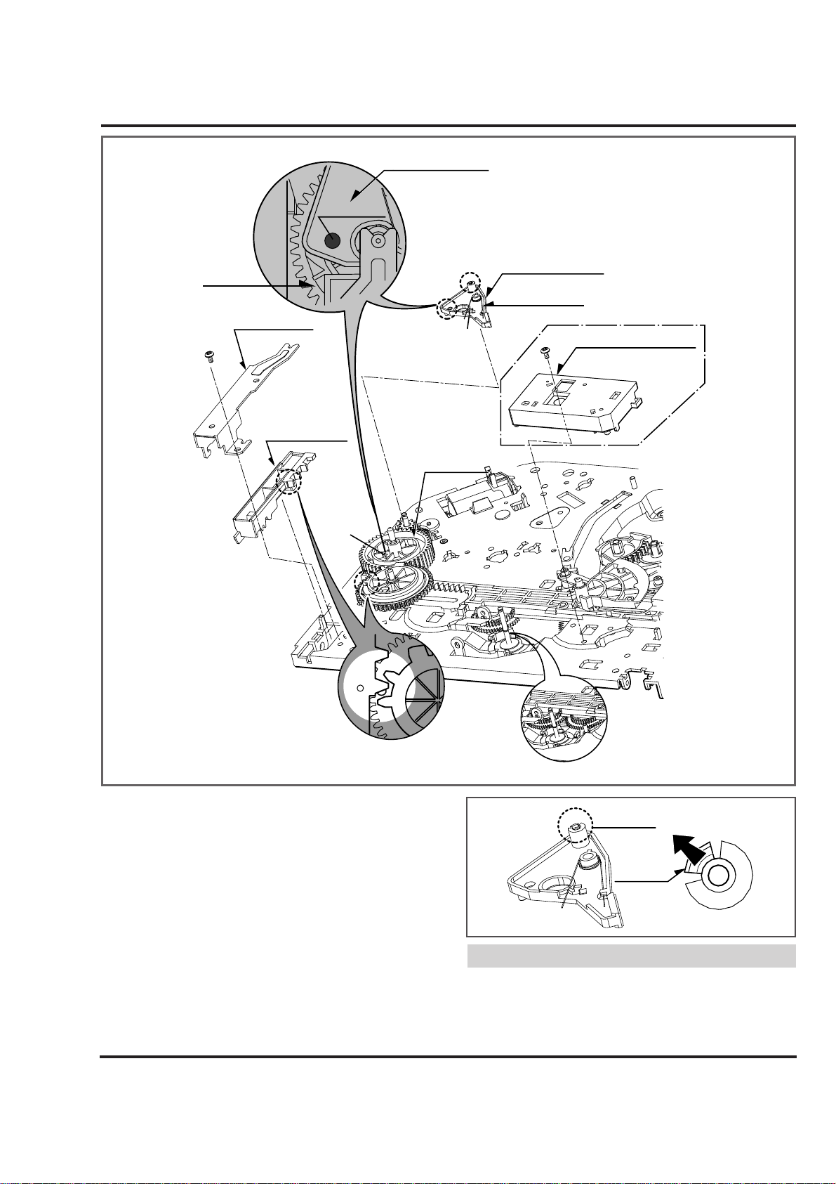
4-10
DECK MECHANISM DISASSEMBLY
Hole (A)+(B)
Fig. A-7
24. Bracket Assembly Jog (Fig. A-7-1)
(Jog shuttle model option)
1) Remove the Screw(S4) and lift up the Bracket Assembly
Jog.
25. Guide Rack F/L (Fig. A-7-2)/
Gear Rack F/L (Fig. A-7-3)
1) Remove the Screw(S4) and lift up the Guide Rack F/L.
2) Lift up the Gear Rack F/L.
26. Brake Assembly Capstan (Fig. A-7-4)
(4HD model option)
1) Hook the Spring Capstan on the Hook(H1).
2) Unhook the Hook(H2) and lift up the Brake Assembly
Capstan.(Refer to Fig. to the right)
(1) When reassembling, confirm that the Hole(A) of the
Brake Assembly Capstan is aligned to the Hole(B) of the
Gear Cam.
(Refer to above Fig. A-7-4).
NOTE
(Fig. A-7-4)
(Fig. A-7-1)
(Fig. A-7-2)
(Fig. A-7-3)
Brake
Assembly Capstan
Gear Cam
Guide Rack F/L
(S4)
Gear Rack F/L
Hole (B)
(H2)
Hole (A)
Gear Cam
(H1)
Barke
Assembly Capstan
(For 4HD Models)
Spring Capstan
(S4)
Barke Assembly Jog
(For Jog Shuttle Models)
(For Jog Shuttle Models)
Hook(H2)
Hook(H2)
Page 12
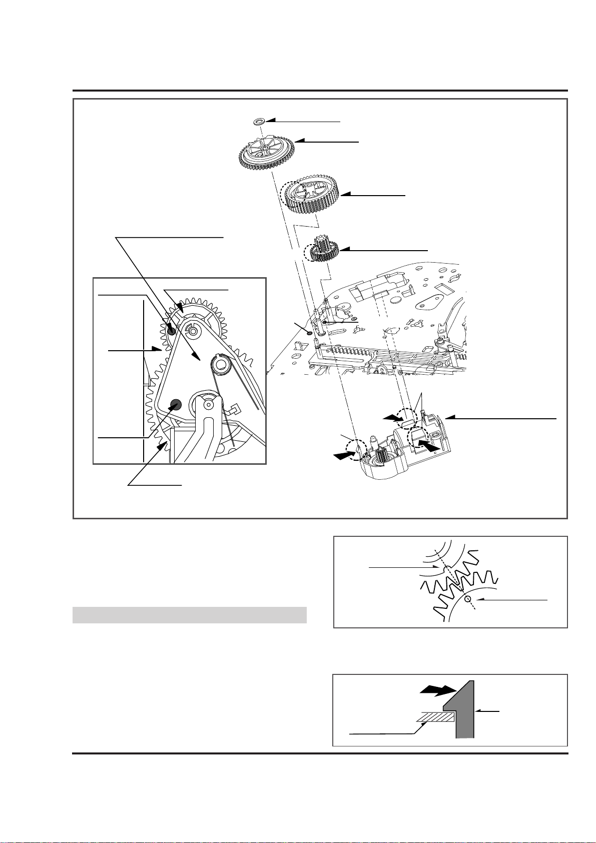
4-11
DECK MECHANISM DISASSEMBLY
Fig. A-8
27. Gear Drive (Fig. A-8-1)/
Gear Cam (Fig. A-8-2)/
Gear Connector (Fig. A-8-3)
1) Remove the Washer(W1) and lift up the Gear Drive.
2) Lift up the Gear Cam.
3) Lift up the Gear Connector.
(1) When reassembling, confirm that the Hole (A) of the
Gear Connector is aligned to the Hole (A') of the Chassis
(Fig. A-8-3).
(2) When reassembling, confirm that the Hole (B) of the
Gear Cam is aligned to the Hole (B') of the Chassis (Fig.
A-8-2).
(3) When reassembling, confirm that the (C) part of the Gear
Cam is aligned to the (D) part of the Gear Drive as shown
Fig. B-3
28. Bracket Assembly L/D Motor (Fig. A-8-4)
1) Unhook the three Hooks(H1),(H2) and push down the
Bracket Assembly L/D Motor.
NOTE
Gear Cam (C)
Gear Drive (D)
Hook (H1), (H2)
Chassis
(Fig. B-3)
(Fig. A-8-1)
(Fig. A-8-2)
(Fig. A-8-3)
(Fig. A-8-4)
Washer (W1)
Gear Drive
Brake Assembly Capstan
Hole (A')+(A)
Chassis
Hole (B')+(B)
(For 4HD Models)
Gear Connector
Hole (B)
Hole (A)
Hole (B')
Gear Cam
Gear Connector
Hole (A')
H1
Bracket Assembly
L/D Motor
H2
Gear Cam
Page 13
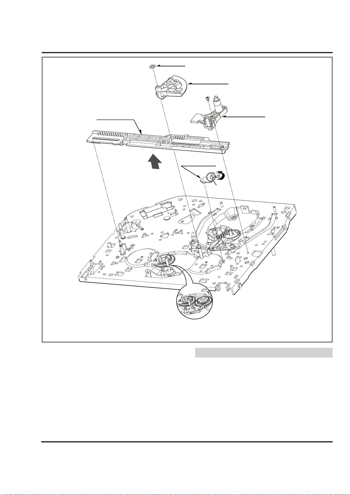
4-12
DECK MECHANISM DISASSEMBLY
(W1)
Fig. A-9
29. Gear Sector (Fig. A-9-1)
1) Remove the Washer(W1) and lift up the Gear Sector.
30. Base Tension (Fig. A-9-2)/
Plate Slider (Fig. A-9-3)/
Lever Tension (Fig. A-9-4)
1) Remove the Screw(S4) and lift up the Base Tension.
2) Lift up the Plate Slider.
3) Hold the (A) Part of the Lever Tension and turn to the
counterclockwise direction, and then lift up the Lever
Tension.
(1) When reassembling, turn the Lever Tension to the clock-
wise direction in maximum.
(2) Push the plate slide right side to be guided by the shaft.
NOTE
(Fig. A-9-1)
(Fig. A-9-2)
(Fig. A-9-4)
(Fig. A-9-3)
Washer
Gear Sector
(S4)
Plate Slider
Base Tension
Lever Tension
(A)
(For Jog Shuttle Models)
Page 14
4-13
DECK MECHANISM DISASSEMBLY
Fig. A-10
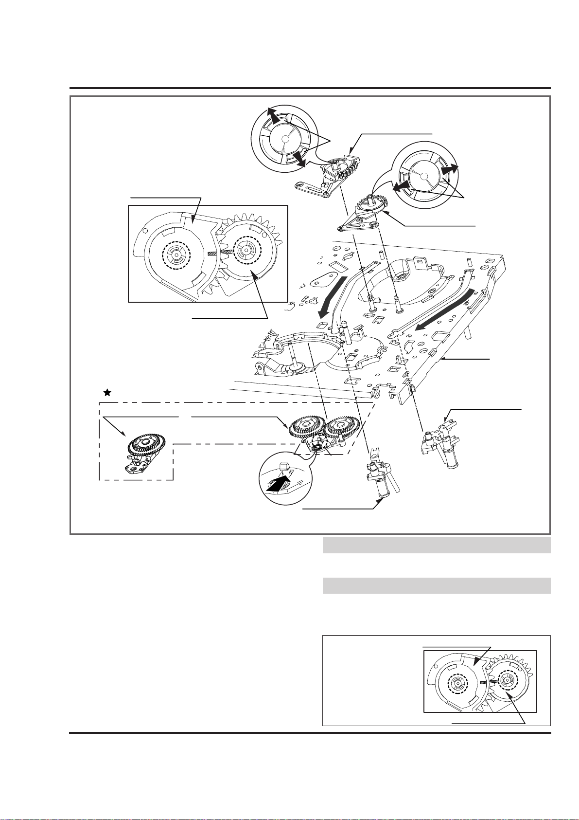
31. Gear Assembly P3 (Fig. A-10-1)/
Gear Assembly P2 (Fig. A-10-2)
1) Unhook the two Hooks(H1) and lift up the Gear Assembly
P3.
2) Unhook the two Hooks(H2) and lift up the Gear Assembly
P2.
32. Base Assembly P3 (Fig. A-10-3)/
Base Assembly P2 (Fig. A-10-4)
1) Move the Base Assembly P3 in the direction of the arrow of
the Chassis Hole(A) and push down the Base Assembly P3.
2) Move the Base Assembly P2 in the direction of the arrow of
the Chassis Hole(B) and push down the Base Assembly P2.
33. Arm Assembly Idler or Arm Assembly
Idler Jog(Fig. A-10-5)
1) Unhook the Hook(H3) and push down the Arm Assembly
Idler Jog.
1) Arm Assembly Idler is for Normal Models.
2) Arm Assembly Idler Jog is for Jog Shuttle Models.
1) When reassembling, confirm that the (A) Part of the Gear
Assembly P3 is aligned to the (B) Part of the Gear Assembly
P2 as shown below.
NOTE
NOTE
(Fig. A-10-1)
(Fig. A-10-2)
(Fig. A-10-4)
(Fig. A-10-3)
(Fig. A-10-5)
(Unloading Condition)
Gear Assembly P3
H1
Gear Assembly P3
Optional Parts
Arm Assembly Idler
(For Normal Models) (
(A)
(B)
Gear Assembly P2
Arm Assembly Idler Jogor
For Jog Shuttle Models)
(A)
(H3)
H2
Gear Assembly P2
(B)
Chassis
Base Assembly P2
Base Assembly P3
Gear Assembly P3
Gear Assembly P2
(A)
(B)
Page 15
4-14
DECK MECHANISM DISASSEMBLY
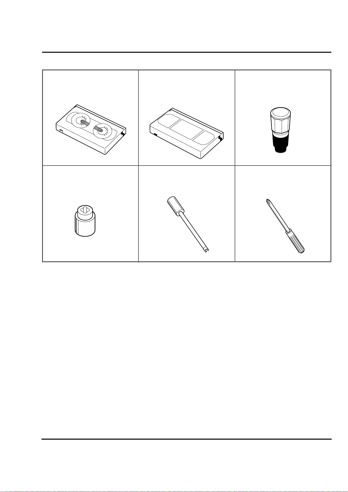
• Tools and Fixfures for Service
1. Cassette Torque meter
1. SRK-VHT-303(Not SVC part)
1. Parts No: D00-D006
4. Torque gauge adaptor
Parts No:D09-R001
5. Post height adjusting driver
Parts No:DTL-0005
6. + Type driver (ø 5)
2. Alignment tape
Parts No NTSC: DTN-001
PAL:DTN-0002
3. Torque gauge
3. 600g.Cm ATG
3. Parts No:D00-D002
SRK
VIDEO
CASSETTE
TORQUE
METER
VHT-303
S
R
K
-
V
H
T
-
S
S
R
K
-
V
H
T
-
T
300
250
200
150
50
0
300
250
200
150
50
0
100
Page 16
4-15
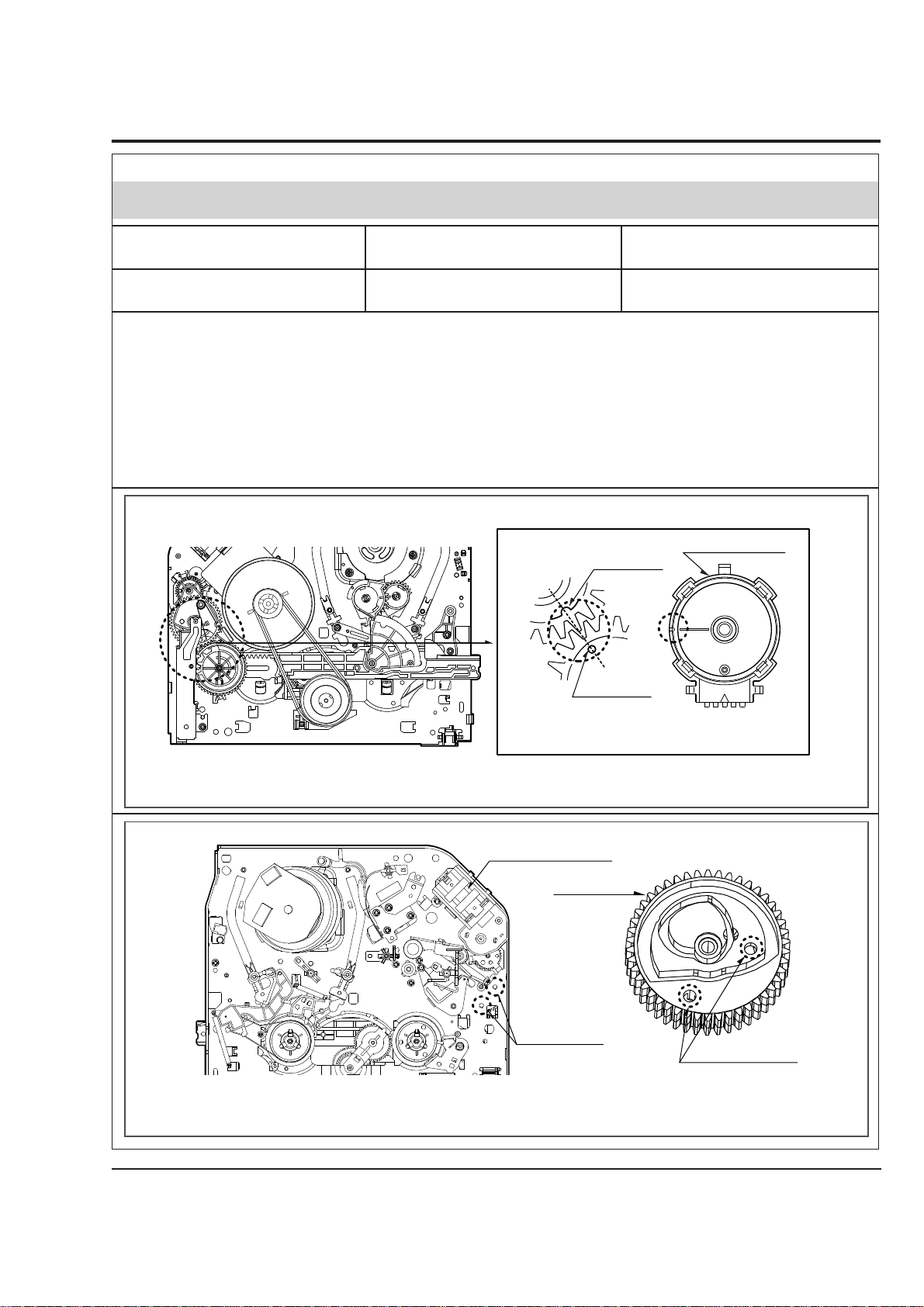
Purpose:To determine if the Mechanism is in the correct position, when a Tape is ejected.
DECK MECHANISM ADJUSTMENT(FOR NORMAL MODELS)
1.Mechanism Alignment Position Check
1) Turn the Power S/W on and eject the Cassette by pressing the Eject Button.
2) Remove the Top Cover and Plate Assembly Top, visually check if the Gear Cam Hole is aligned with the
Chassis Hole as below Fig. C-2.
3) IF not, rotate the Shaft of the Loading Motor to either
Clockwise or Counterclockwise until the Alignment is
as below Fig. C-2.
4) Remove the Screw which fixes the Deck Mechanism
and Main Frame and confirm if the Gear Cam is aligned
with the Gear Drive as below Fig. C-1(A).
5) Confirm if the Mode S/W on the Main P.C.Board is
aligned as below Fig. C-1(B).
6) Remount the Deck Mechanism on the Main P.C.Board
and check each operation.
Mode S/W
Gear Cam
Gear Drive
(A)
(B)
L/D Motor Assembly
Gear Cam Hole
Gear Cam
Chassis Hole
Test Equipment/ Fixture
• Blank tape
Test Conditions (Mechanism
Condition)
• Eject Mode (with Cassette ejected)
Check Point
• Mechanism and Mode Switch Position
Fig. C-1
Fig. C-2
CHECK DIAGRAM
BOTTOM VIEW
TOP VIEW
Gear Cam (o) and Gear Drive (o) groove alignment
Page 17
4-16
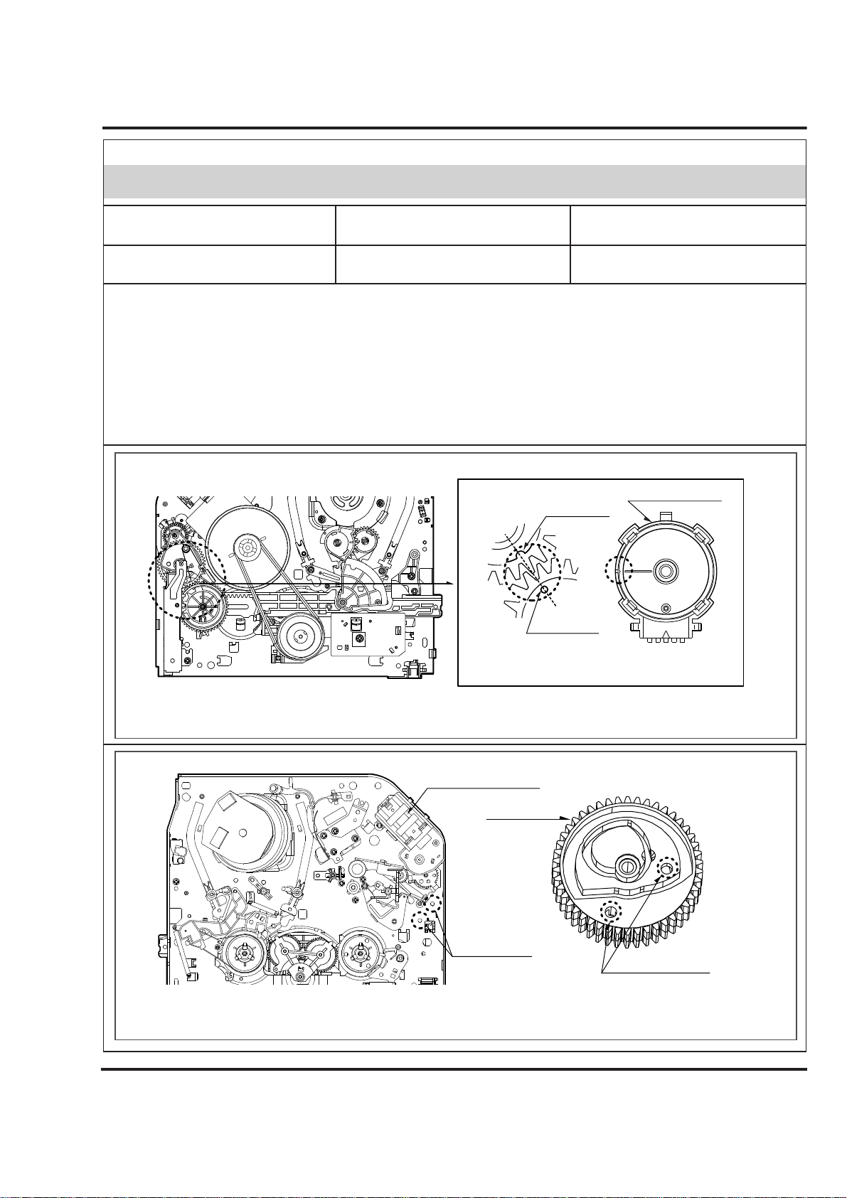
Purpose:To determine if the Mechanism is in the correct position, when a Tape is ejected.
DECK MECHANISM ADJUSTMENT(FOR JOG SHUTTLE MODELS)
1.Mechanism Alignment Position Check
1) Turn the Power S/W on and eject the Cassette by pressing the Eject Button.
2) Remove the Top Cover and Plate Assembly Top, visually check if the Gear Cam Hole is aligned with the
Chassis Hole as below Fig. C-2.
3) IF not, rotate the Shaft of the Loading Motor to either
Clockwise or Counterclockwise until the Alignment is
as below Fig. C-2.
4) Remove the Screw which fixes the Deck Mechanism
and Main Frame and confirm if the Gear Cam is aligned
with the Gear Drive as below Fig. C-1(A).
5) Confirm if the Mode S/W on the Main P.C.Board is
aligned as below Fig. C-1(B).
6) Remount the Deck Mechanism on the Main P.C.Board
and check each operation.
Mode S/W
Gear Cam
Gear Drive
(A)
(B)
L/D Motor Assembly
Gear Cam Hole
Gear Cam
Chassis Hole
Test Equipment/ Fixture
• Blank tape
Test Conditions (Mechanism
Condition)
• Eject Mode (with Cassette ejected)
Check Point
• Mechanism and Mode Switch Position
Fig. C-1
Fig. C-2
CHECK DIAGRAM
BOTTOM VIEW
TOP VIEW
Gear Cam (o) and Gear Drive (o) groove alignment
Page 18
4-17
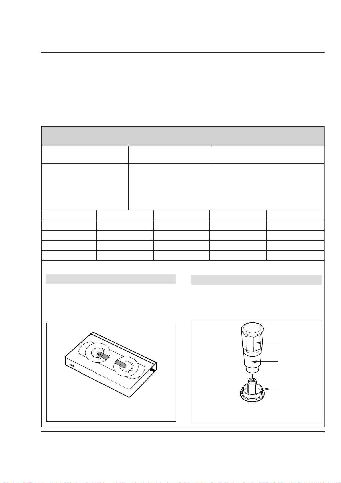
Purpose: To insure smooth Transport of the Tape during each Mode of Operation.
If the Tape Transport is abnormal, then check the Torque as indicated by the chart below.
DECK MECHANISM ADJUSTMENT
2. Preparation for Adjustment (To set the
Deck Mechanism to the Loading state
without inserting a Cassette Tape).
1) Unplug the Power Cord from the AC Outlet.
2) Disassemble the Top Cover and Plate Assembly Top.
3) Plug the Power Cord into the AC Outlet.
4) Turn the Power S/W on and push the Lever Stopper
(L),(R) of the Holder Assembly CST to the back for
Loading the Cassette without Tape.
Cover the Holes of the End Sensors at the both sides of
the Bracket Side(L) and Bracket Assembly Door to prevent a light leak.
Then The Deck Mechanism drives to the Stop Mode.
In this case, The Deck Mechanism can accept inputs of
each mode, however the Rewind and Review Operation
can not be performed for more than a few seconds
because the Take-up Reel Table is in the Stop State
and can not be detected the Reel Pulses.
3. Checking Torque
The Values are measured by using a Torque Gauge and
Torque Gauge Adaptor with the Torque Gauge affixed.
The Torque reading to measure occurs when the Tape
abruptly changes direction from Fast Forward of Rewind
Mode, when quick bracking is applied to both Reels.
SRK
VIDEO
CASSETTE
TORQUE
METER
VHT-303
S
R
K
-
V
H
T
-
S
S
R
K
-
V
H
T
-
T
300
250
200
150
50
0
300
250
200
150
50
0
100
Test Equipment/ Fixture
• Torque Gauge(600g/cm ATG)
• Torque Gauge Adaptor
• Cassette Torque Meter
SRK-VHT-303
Checking Method
• Perform each Deck Mechanism Mode without
inserting a Cassette Tape(Refer to above No.2
Preparation for Adjustment).
• Read the Measurement of the Take-up or Supply
Reels on the Cassette Torque Meter(Fig. C-3-2).
• Attach the Torque Gauge Adaptor to the Torque
Gauge and then read the Value of it(Fig. C-3-1).
NOTE:
Fig. C-3-2
Fig. C-3-1
Torque Gauge
Torque Gauge
Adaptor
Reel Table
Item
Fast Forward Torque
Rewind Torque
Play Take-Up Torque
Review Torque
Mode
Fast Forward
Rewind
Play
Review
Test Equipment
Cassette Torque Gauge
Cassette Torque Gauge
Cassette Torque Meter
Cassette Torque Meter
Take-Up Reel
Supply Reel
Take-Up Reel
Supply Reel
More than 400g/cm
More than 400g/cm
70~120g/cm
130~210g/m
Measurement Reel
Measurement Values
Test Conditions
(Mechanism Condition)
• Play (FF) or Review (REW) Mode
NOTE:
• Cassette Torque Meter (SRK-VHT-303)
• Torque Gauge (600g.cm ATG)
Page 19
4-18
DECK MECHANISM ADJUSTMENT
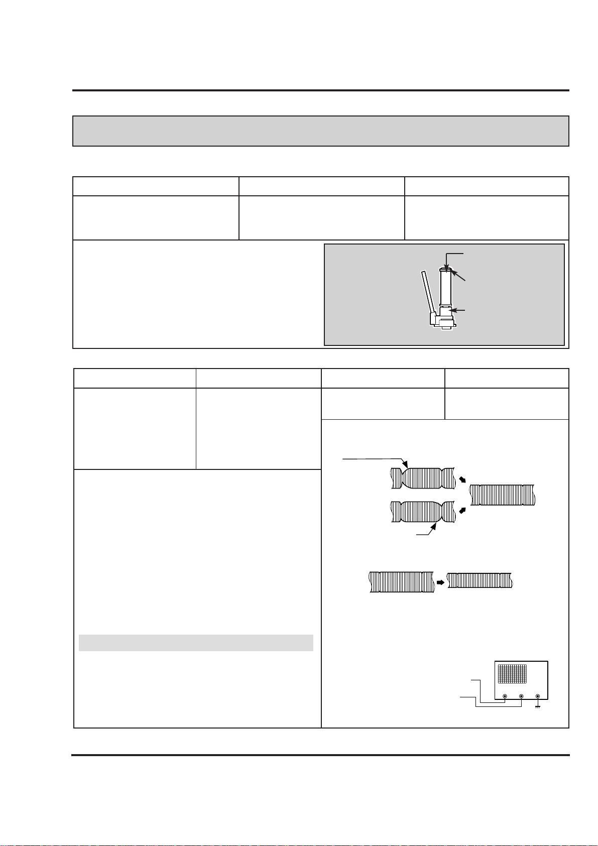
4.Guide Roller Height Adjustment
Adjustment Procedure
1) Confirm if the Tape runs along the Tape Guide Line of the
Lower Drum.
2) If the Tape runs the Bottom of the Guide Line, turn the Guide
Roller Height Adjustment Screw to Clockwise direction.
3) If it runs the Top, turn to Counterclockwise direction.
4) Adjust the Height of the Guide Roller to be guided to the Guide
Line of the Lower Drum from the Starting and Ending Point of
the Drum.
Purpose: To regulate the Height of the Tape so that the Bottom of the Tape runs along the
Tape Guide Line on the Lower Drum.
Test Equipment/ Fixture
• Post Height Adjusting Driver
Test Conditions (Mechanism Condition)
• Play or Review Mode
Adjustment Point
• Guide Roller Height Adjustment
screws on the Supply and Take-Up
Guide Rollers.
Fig. C-4-1
Upper Flange
Guide Roller
Retaining Screw
Guide Roller Height
Adjustment screw
ADJUSTMENT DIAGRAM
Test Equipment/Fixture
• Oscilloscope
• Alignment Tape
• Post Height Adjusting
Driver
Test Equipment Connection Points
• CH-1:PB RF Envelope
• CH-2:NTSC: SW 30Hz
PAL: SW 25Hz
• Head Switching Output
Point
• RF Envelope Output
Point
Test Conditions VCR(VCP) State
• Play an Alignment Tape
Adjustment Point
• Guide Roller Height
Adjustment Screws
Fig. C-4-2
Fig. C-4-3
P3 POST
ADJUSTMENT
P2 POST
ADJUSTMENT
Turn the Roller Guide Height
Adjustment Screw slightly
to flatten the waveform.
Tracking control at center
RF ENVELOPE OUTPUT TEST POINT
OSCILLOSCOPE
HEAD SWITCHING OUTPUT TEST
POINT
Turn(Move) the tracking
control to both directions
4-1. Preliminary Adjustment
4-2. Precise Adjustment
Adjustment Procedure
1) Play an Alignment Tape after connecting the Probe of the
Oscilloscope to the RF Envelope Output Test Point and
Head Switching Output Test Point.
2) Tracking Control(in PB Mode) : Center Position(When
this Adjustment is performed after the Drum Assembly
has been replaced, set the Tracking Control so that the
RF Output is Maximum).
3) Height Adjustment Screw : Flatten the RF Waveform.
(Fig. C-4-2)
4) Turn(Move) the Tracking Control(in PB Mode)
Clockwise and Counterclockwise.(Fig. C-4-3)
5) Check that any Drop of RF Output is uniform at the
Start and End of the Waveform.
If the adjustment is excessive or insufficient the tape
will jam or fold.
NOTE
Waveform Diagrams
Connection Diagram
Page 20
4-19
DECK MECHANISM ADJUSTMENT
5. Audio/Control (A/C) Head Adjustment
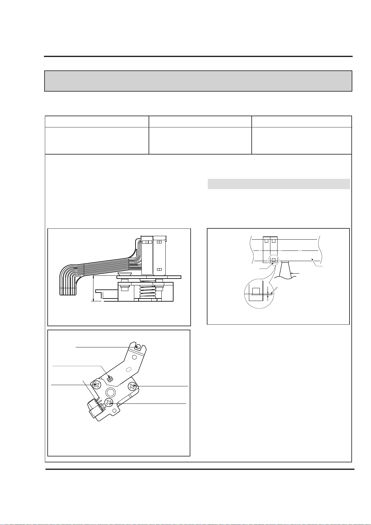
Purpose: To insure that the Tape passes accurately over the Audio and Control Tracks in exact
Alignment in both the Record and Playback Modes.
Test Equipment/ Fixture
• Blank Tape
• Screw Driver(+) Type 5mm
• Play the blank tape
Test Conditions (Mechanism Condition)
Adjustment Point
• Tilt Adjustment Screw(C)
• Height Adjustment Screw(B)
• Azimuth Adjustment Screw(A)
Fig. C-5-1
A/C Head Base
Fig. C-5-2
Height Adjustment
Screw(B)
Tilt Adjustment
Screw(C)
Azimuth Adjustment
Screw(A)
X-Value Adjustment
Hole
Fixed Screw
Fig. C-5-3
A/C Head
Tape
Tape
0.2~0.25mm
P4
5-1. Preliminary Adjustment (Height and Tilt Adjustment)
Perform the Preliminary Adjustment, when there is no Audio Output Signal with the Alignment Tape.
1) Initially adjust the Base Assembly A/C Head as shown
Fig. C-5-1 by using the Height Adjustment Screw(B).
2) Play a Blank Tape and observe if the Tape passes accurately over the A/C Head without Tape Curling or
Folding.
3) If Folding or Curling is occured then adjust the Tilt
Adjustment Screw(C) while the Tape is running to
resemble Fig. C-5-3.
4) Reconfirm the Tape Path after Playback about 4~5 seconds.
Ideal A/C head height occurs, when the tape runs
between 0.2~0.25mm above the bottom edge of the A/C
head core.
NOTE
Adjustment Procedure/Diagrams
A/C Head Assembly
10.9
Page 21
4-20
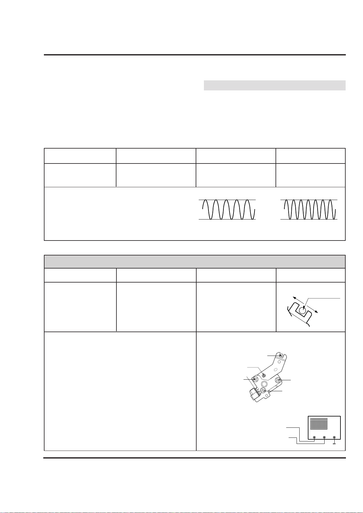
Purpose: To obtain compatibility with other VCR(VCP) Models.
DECK MECHANISM ADJUSTMENT
5-2. Confirm that the Tape passes smoothly
between the Take-up Guide and Pinch
Roller(using a Mirror or the naked eye).
1) After completing Step 5-1.(Preliminary Adjustment),
check that the Tape passes around the Take-up Guide
and Pinch Roller without Folding or Curling at the Top or
Bottom.
(1) If Folding or Curling is observed at the Bottom of
the Take-up Guide then slowly turn the Tilt
Adjustment Screw(C) in the Clockwise direction.
(2) If Folding or Curling is observed at the Top of it then
slowly turn the Tilt Adjustment Screw(C) in the
Counterclockwise direction.
Check the RF Envelope after adjusting the A/C Head, if
the RF Waveform differs from Fig. C-5-4, performs
Precise Adjustment to flat the RF Waveform.
Test Equipment/ Fixture
• Oscilloscope
• Alignment Tape(SP)
• Screw Driver(+) Type 5mm
Connection Point
• Audio output jack
Test Conditions
(Mechanism Condition)
• Play an Alignment Tape
1KHz, 7KHz Sections
Adjustment Point
• Azimuth Adjustment Screw(A)
• Height Adjustment Screw(B)
1) Connect the Probe of the Oscilloscope to Audio Output
Jack.
2) Alternately adjust the Azimuth Adjustment Screw(A) and
the Tilt Adjustment Screw(C) for Maximum Output of the
1Khz and 7Khz segments, while maintaining the flattest
Envelope differential between the two Frequencies.
Adjustment Procedure
5-3. Precise Adjustment (Azimuth adjustment)
6. X-Value Adjustment
Fig. C-5-4
1KHZ
• Oscilloscope
• Alignment tape(SP only)
• Screw Driver(+) Type 5mm
• CH-1: PB RF Envelope
• CH-2: NTSC: SW 30Hz
PAL: SW 25Hz
• Head Switching Output
Test Point
• RF Envelope Output Test
Point
Test Conditions
(Mechanism Condition)
• Play an Alignment Tape
Adjustment PointConnection PointTest Equipment/ Fixture
Adjustment Procedure
1) Release the Automatic Tracking to run long enough for
Tracking to complete it’s Cycle.
2) Loosen the Fixed Mounting Screw and move the Base
Assembly A/C Head in the direction as shown in the
Diagram to find the center of the peak that allows for the
maximum Waveform Envelope.
This method should allow the 31um Head to be centrally
located over the 58um Tape Track.
3) Tighten the Base Assembly A/C Head mounting Screw.
7KHZ
A:Maximum
B:Maximum
Left
Right
Groove at the
Base A/C
Height Adjustment Screw(B)
Tilt Adjustment Screw(C)
Azimuth Adjustment
Screw(A)
X-Value Adjustment Hole
Fixed Screw
RF ENVELOPE OUTPUT TEST POINT
OSCILLOSCOPE
HEAD SWITCHING OUTPUT TEST POINT
Connection Diagram
Adjustment Diagram
NOTE:
CH-1
CH-2
Page 22
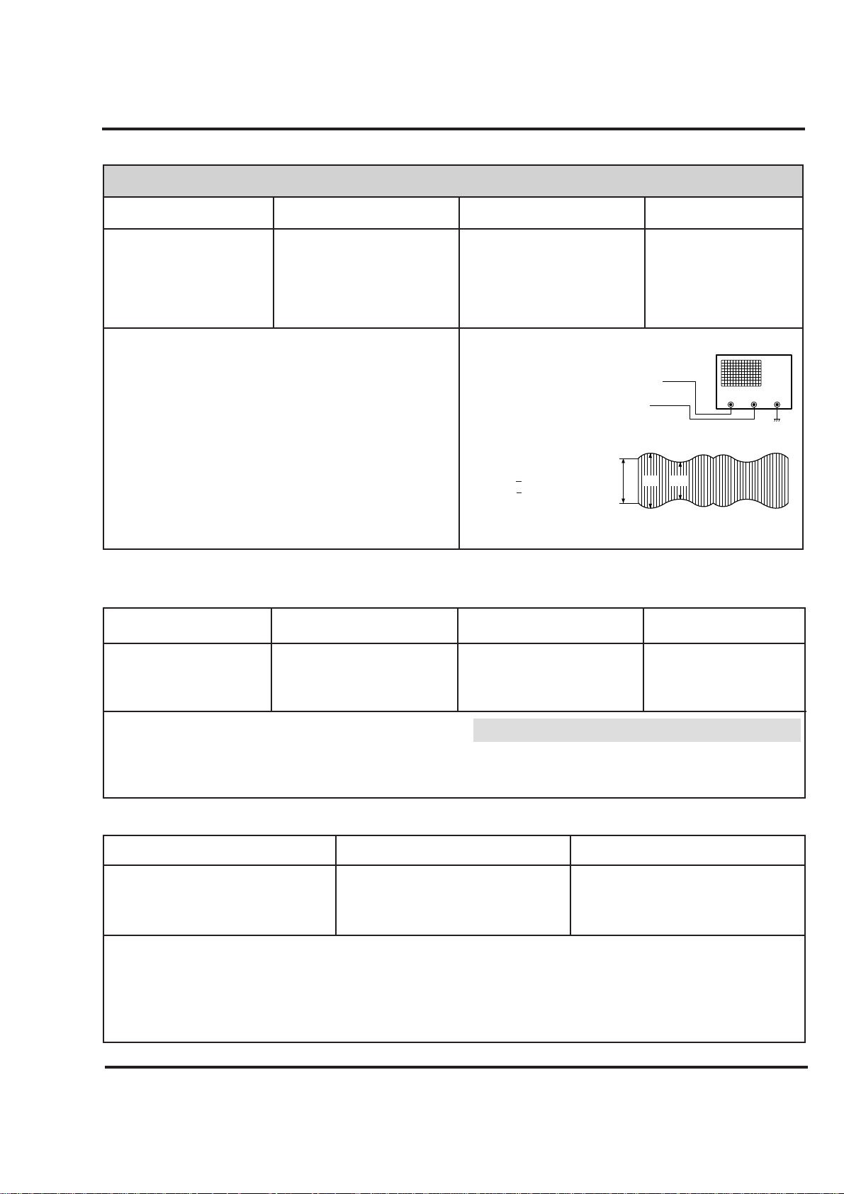
4-21
Purpose: To correct for shift in the Roller Guide and X value after replacing the Drum.
8-2.Check for tape curling or jamming
Test Equipment/ Fixture
• T-160 Tape
• T-120 Tape
Specification
• Be sure there is no tape jamming or curling
at the begining, middle or end of the tape.
VCR(VCP) State
•
Run the CUE, REV play mode at the
beginning and the end of the tape.
Test Conditions (Mechanism Condition)
1) Confirm that the tape runs smoothly around the roller
guides, drum and A/C head assemblies while abruptly
changing operating modes from Play to CUE or REV.
This is to be checked at the begining, middle and end
sections of the cassette.
2) Confirm that the tape passes over the A/C head assembly as indicated by proper audio reproduction and proper tape counter performance.
Checking Procedure
DECK MECHANISM ADJUSTMENT
7. Adjustment after Replacing Drum Assembly (Video Heads)
Test Equipment/ Fixture
• Oscilloscope
• Alignment tapes
• Blank Tape
• Post Height Adjusting Driver
• Screw Driver(+) Type 5mm
Connection Point
• CH-1: PB RF Envelope
• CH-2: NTSC: SW 30Hz
PAL: SW 25Hz
• Head Switching Output
Test Point
• RF Envelope Output Test Point
Test Conditions
(Mechanism Condition)
• Play the blank tape
• Play an alignment tape
Adjustment Points
• Guide Roller Precise
Adjustment
• Switching Point
• Tracking Preset
• X-Value
Checking/Adjustment Procedure
Play a blank tape and check for tape curling or creasing around
the roller guide. If there is a problem then follow the procedure
4. "Guide Roller Height" and 5. "Audio Control(A/C) Head
Adjustment".
RF ENVELOPE OUTPUT TEST POINT
OSCILLOSCOPE
HEAD SWITCHING OUTPUT TEST
POINT
Connection Diagram
Waveform
V1/V MAX ≤0.7
V2/V MAX ≤0.8
RF ENVELOPE OUTPUT
Fig. C-7
8. Check the Tape Travel after Reassembling Deck Assembly.
8-1.Check Audio and RF Locking Time during playback and after CUE or REV (FF/REW)
Test Equipment/ Fixture
• Oscilloscope
• Alignment tapes(with 6H
3kHz Color Bar Signal)
• Stop Watch
Specification
• RF Locking Time: Less than 5 sec.
• Audio Locking Time:Less than
10sec
Test Equipment
Connection Points
• CH-1: PB RF Envelope
• CH-2: Audio Output
• RF Envelope Output Point
• Audio Output Jack
Test Conditions
(Mechanism Condition)
• Play an alignment tape
(with 6H 3kHz Color Bar
Signal)
Checking Procedure
Play an alignment tape then change the operating mode to
CUE or REV and confirm if the unit meets the above listed
specifications.
1) CUE is fast forward mode (FF)
2) REV is the rewind mode (REW)
3) Referenced to the Play mode
NOTES:
V1
V
V2
CH1 CH2
Connection Points
Page 23
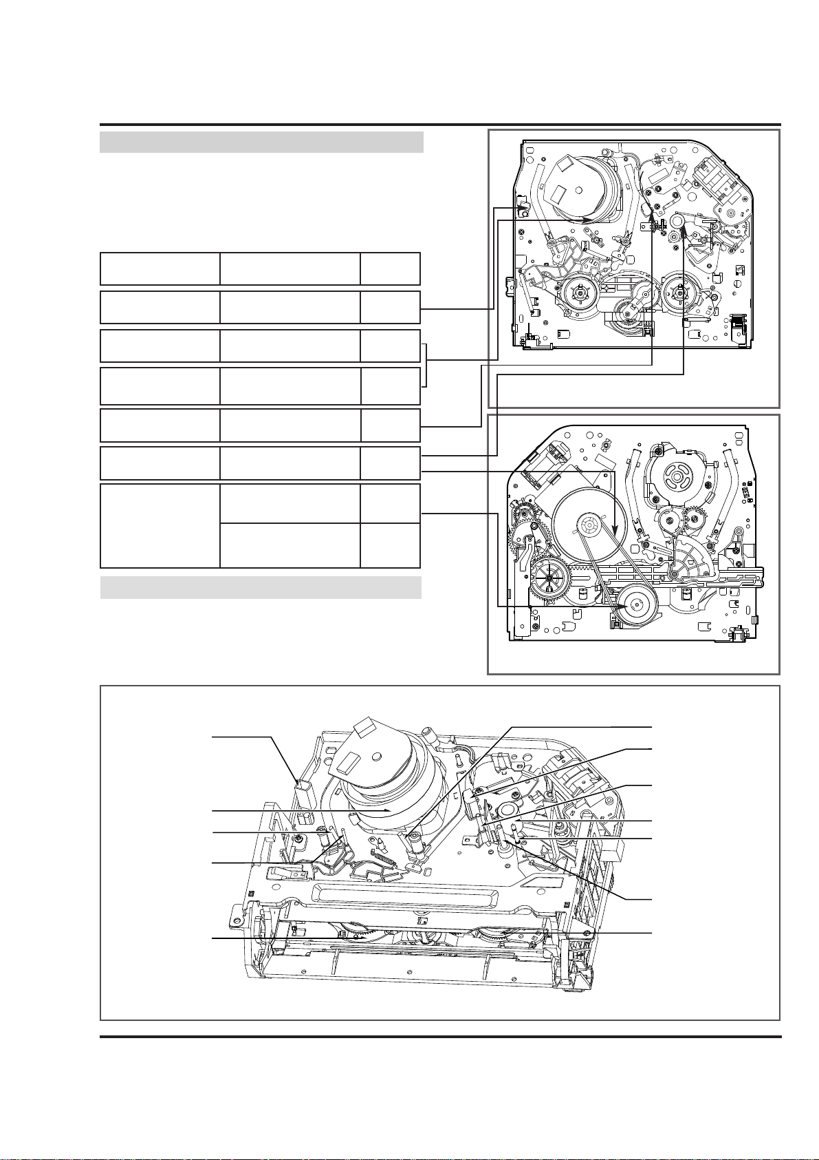
4-22
MAINTENANCE/INSPECTION PROCEDURE(FOR NORMAL MODELS)
(4) F/E Head
(3) P1 Post
(6) Drum Assembly
(Video Head)
(5) Base
Assembly P2
(2) Tension Post
(1) Supply Reel
(7) Base Assembly P3
The following faults can be remedied by cleaning and oiling.
Check the needed lubrication and the conditions of cleanliness in the unit.
Check with the customer to find out how often the unit is
used, and then determine that the unit is ready for inspection
and maintenance. Check the following parts.
1 Check before starting repairs
Phenomenon Inspection
Replace-
ment
Color beats Dirt on full-erase head
o
Poor S/N, no color
Dirt on video head
Vertical or
Horizontal jitter
Dirt on Audio/control head
Dirt on pinch roller
If locations marked with o do not operate normally after
cleaning, check for wear and replace.
See the EXPLODED VIEWS at the end of this manual as
well as the above illustrations See the Greasing (Page 4-22)
for the sections to be lubricated and greased.
NOTE
o
o
o
o
Dirt on video head
Dirt on tape transport system
Low volume,
Sound distorted
Tape does not run.
Tape is slack
o
In Review and
Unloading (off mode),
the Tape is rolled up
loosely.
Clutch Assembly D33K
Torque reduced
Cleaning Drum and
transport system
Fig. C-9-3
(8) A/C Head
(9) P4 Post
(11) Pinch Roller
(12) Take-up Guide Post
(10) Capstan Shaft
(13) Take-up Reel
* No. (1)~(13) Indicates the Tape Path to be traveled from Supply Reel to Take-up Reel.
Fig. C-9-1 Top VIEW
Fig. C-9-2 BOTTOM VIEW
F/E Head
Video Head
A/C Head
Pinch Roller
Belt Capston
Clutch
Assembly D33K
Fig. C-9-3 Tape Transport System
Page 24
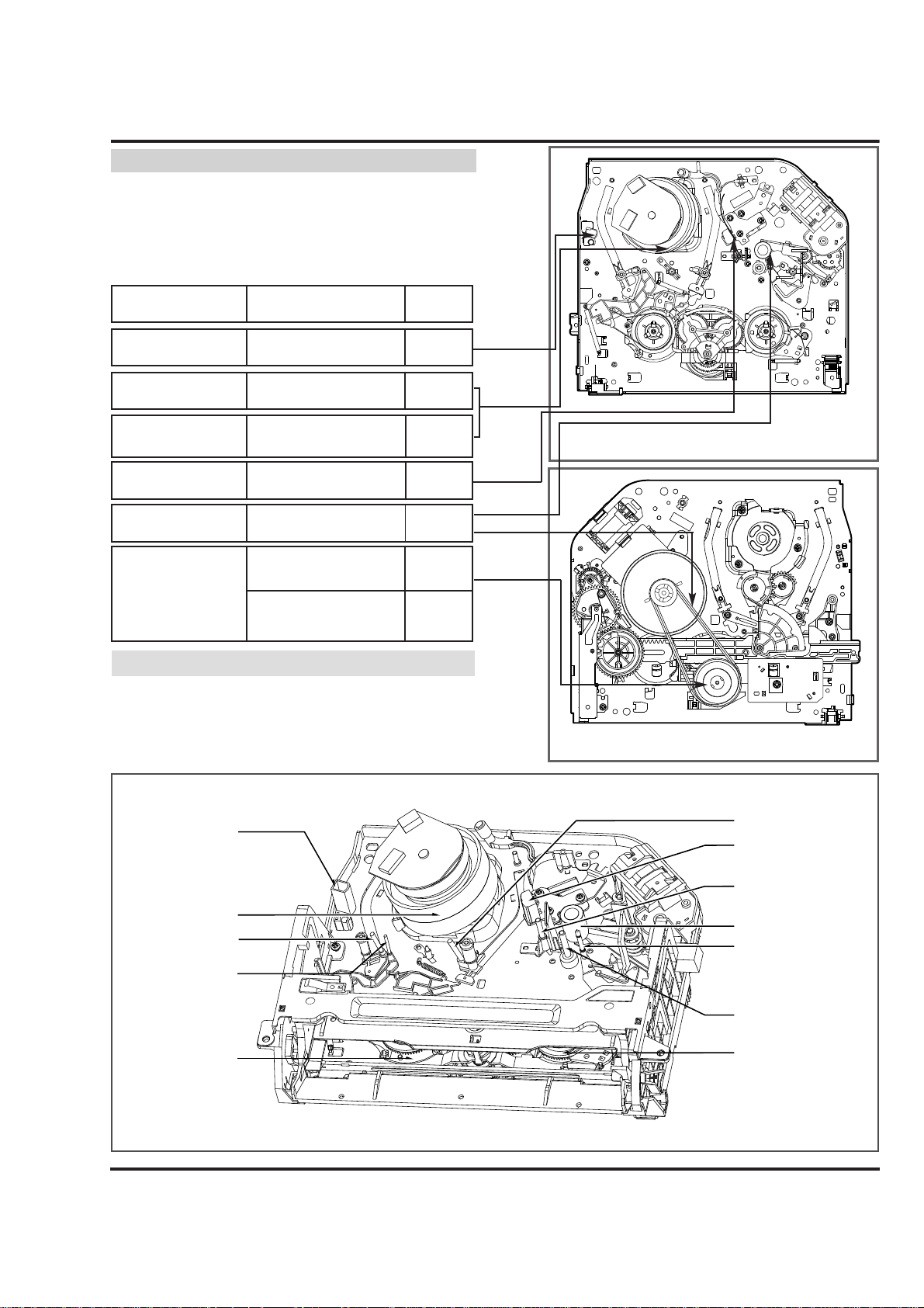
4-23
MAINTENANCE/INSPECTION PROCEDURE(FOR JOG SHUTTLE MODELS)
(4) F/E Head
(3) P1 Post
(6) Drum Assembly
(Video Head)
(5) Base
Assembly P2
(2) Tension Post
(1) Supply Reel
(7) Base Assembly P3
The following faults can be remedied by cleaning and oiling.
Check the needed lubrication and the conditions of cleanliness in the unit.
Check with the customer to find out how often the unit is
used, and then determine that the unit is ready for inspection
and maintenance. Check the following parts.
1 Check before starting repairs
Phenomenon Inspection
Replacement
Color beats Dirt on full-erase head
o
Poor S/N, no color
Dirt on video head
Vertical or
Horizontal jitter
Dirt on Audio/control head
Dirt on pinch roller
If locations marked with o do not operate normally after cleaning, check for wear and replace.
See the EXPLODED VIEWS at the end of this manual as well
as the above illustrations See the Greasing (Page 4-22) for the
sections to be lubricated and greased.
NOTE
o
o
o
o
Dirt on video head
Dirt on tape transport system
Low volume,
Sound distorted
Tape does not run.
Tape is slack
o
In Review and
Unloading (off mode),
the Tape is rolled up
loosely.
Clutch Assembly D33K
Torque reduced
Cleaning Drum and
transport system
Fig. C-9-3
(8) A/C Head
(9) P4 Post
(11) Pinch Roller
(12) Take-up Guide Post
(10) Capstan Shaft
(13) Take-up Reel
* No. (1)~(13) Indicates the Tape Path to be traveled from Supply Reel to Take-up Reel.
Fig. C-9-1 Top VIEW
Fig. C-9-2 BOTTOM VIEW
F/E Head
Video Head
A/C Head
Pinch Roller
Belt Capston
Clutch
Assembly D33K
Fig. C-9-3 Tape Transport System
Page 25
4-24
MAINTENANCE/INSPECTION PROCEDURE
The recording density of a VCR(VCP) is much higher than
that of an audio tape recorder. VCR(VCP) components must
be very precise, at tolerances of 1/1000mm, to ensure compatiblity with other VCRs. If any of these components are
worn or dirty, the symptoms will be the same as if the part is
defective. To ensure a good picture, periodic inspection and
maintenance, including replacement of worn out parts and
lubrication, is necessary.
Schedules for maintenance and inspection are not fixed
because they vary greatly according to the way in which the
customer uses the VCR(VCP), and the environment in which
the VCR(VCP) is used.
But, in general home use, a good picture will be maintained
if inspection and maintenance is made every 1,000 hours.
The table below shows the relation between time used and
inspection period.
Table 1
(1) Grease : Kanto G-311G (Blue) or equivalent
(2) Isopropyl Alcohol or equivalent
(3) Cleaning Patches
(4) Grease : Kanto G-381(Yellow) : Used only for Reel S and
Reel T
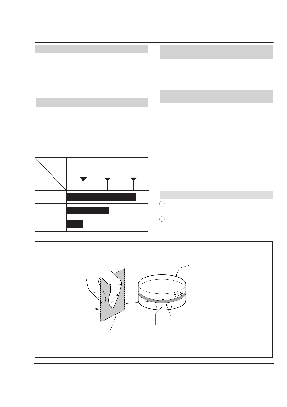
(1) Cleaning video head
First use a cleaning tape. If the dirt on the head is too
stubborn to remove by tape, use the cleaning patch. Coat
the cleaning patch with Isopropyl Alcohol. Touch the
cleaning patch to the head tip and gently turn the
head(rotating cylinder) right and left.
(Do not move the cleaning patch vertically. Make sure
that only the buckskin on the cleaning patch comes into
contact with the head. Otherwise, the head may be damaged.)
Thoroughly dry the head. Then run the test tape. If lsopropyl Alcohol remains on the video head, the tape may
be damaged when it comes into contact with the head
surface.
(2) Clean the tape transport system and drive system, etc,
by wiping with a cleaning patch wetted with Isporopyl
Alcohol.
1 It is the tape transport system which comes into contact
with the running tape. The drive system consists of those
parts which moves the tape.
2 Make sure that during cleaning you do not touch the tape
transport system with the tip of a screw driver and no that
force is that would cause deforming or damage applied to
the system.
2.Required Maintenance
3.Scheduled Maintenance
5) Maintenance Procedure
5-1) Cleaning
NOTES:
About 1
year
One hour
Two hours
Three hours
When
inspection is
necessary
Average
hours used
per day
About 18
months
About 3
years
4.Supplies Required for Inspection and
Maintence
Fig. C-9-4
Drum
(Rotating Cylinder)
Head Tip
Coat With Isopropyl Alcohol
Touch this section of cleaning
patch to the head tip and gently
turn the Drum (Rotating Cylinder)
Cleaning Patch
Page 26
4-25
MAINTENANCE/INSPECTION PROCEDURE
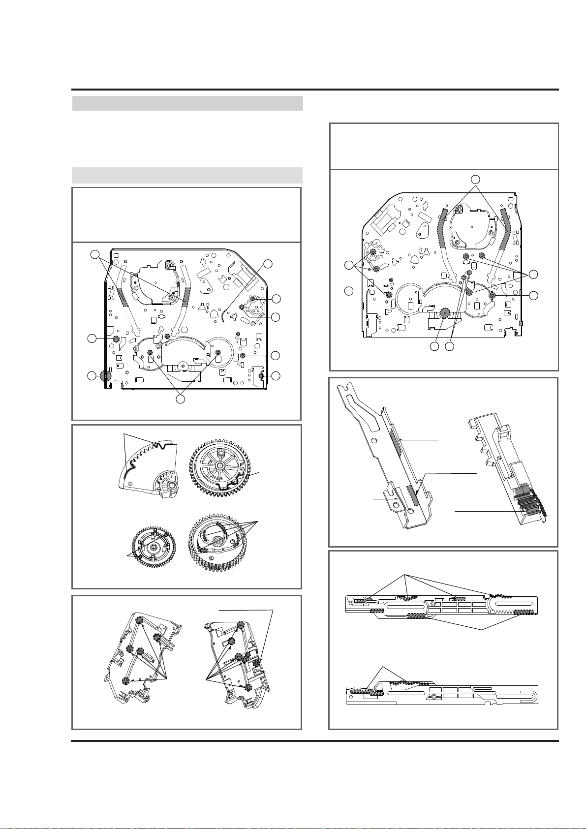
(1) Greasing guidelines
Apply grease, with a cleaning patch. Do not use excess
grease. It may come into contact with the tape transport
or drive system. Wipe any excess and clean with clean
ing patch wetted in Isopropyl Alcohol.
(2) Periodic greasing
Grease specified locations every 5,000 hours.
5-2) Greasing
NOTE:Greasing Points
1)Loading Path Inside & Top side
2)Base Tension Boss inside Hole
3)Arm Assembly F/L "U" Groove
4)Arm Take-up Rubbing Section
5)L/D Motor Worm Wheel Part
6)Shaft
7)Arm Assembly F/L of Buming
Inside Hole
8)Reel S, T Shaft (G381:Yellow)
9)Brake T Groove
Gear Assembly Up/D
Gear Drive
Gear Sector
Gear Cam
Press
Cam Part
Cam Part
Gear Part
Stopper Part
Bracket Side (L)
Bracket Assembly Door
1) Loading Path Inside & Top side
2) Shaft
3) Gear Rack F/L Moving Section
4) Shaft
5) Lever Tension Groove
6) Clutch Assembly D33 Shaft
7) Brake "S" Rubbing Section
Chassis (Top)
Chassis (Bottom)
Guide Rack F/L Gear Rack F/L
Side
Bottom
inside
Bottom
Cam &
Gear Part
Cam Part
Cam Part
Gear Part
1
2
4
5
6
9
1
2
3
76
4
5
3
8
Guide Rail
7
Plate Slider (Top)
Plate Slider (Bottom)
Page 27
4-26
MECHANISM TROUBLESHOOTING GUIDE
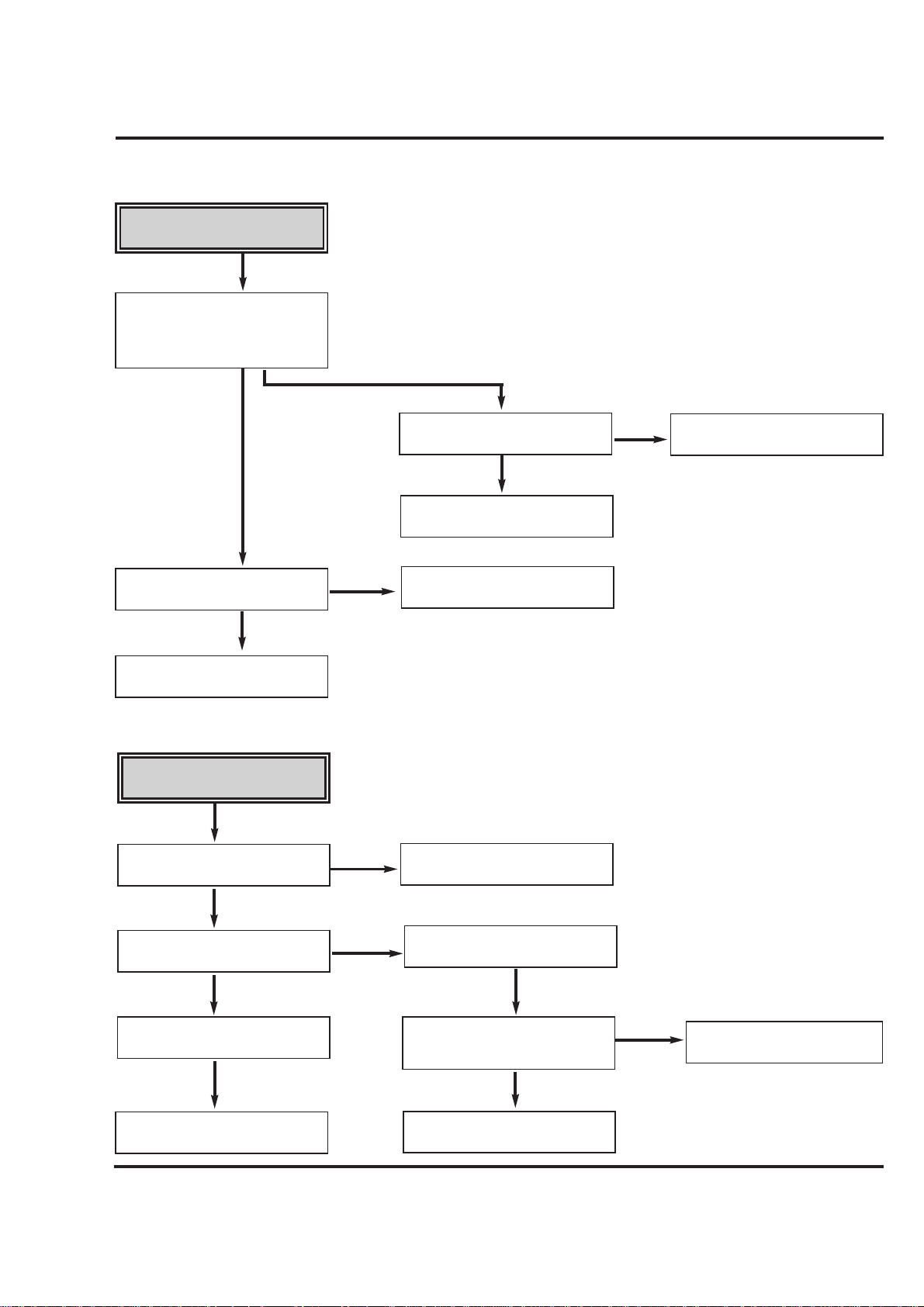
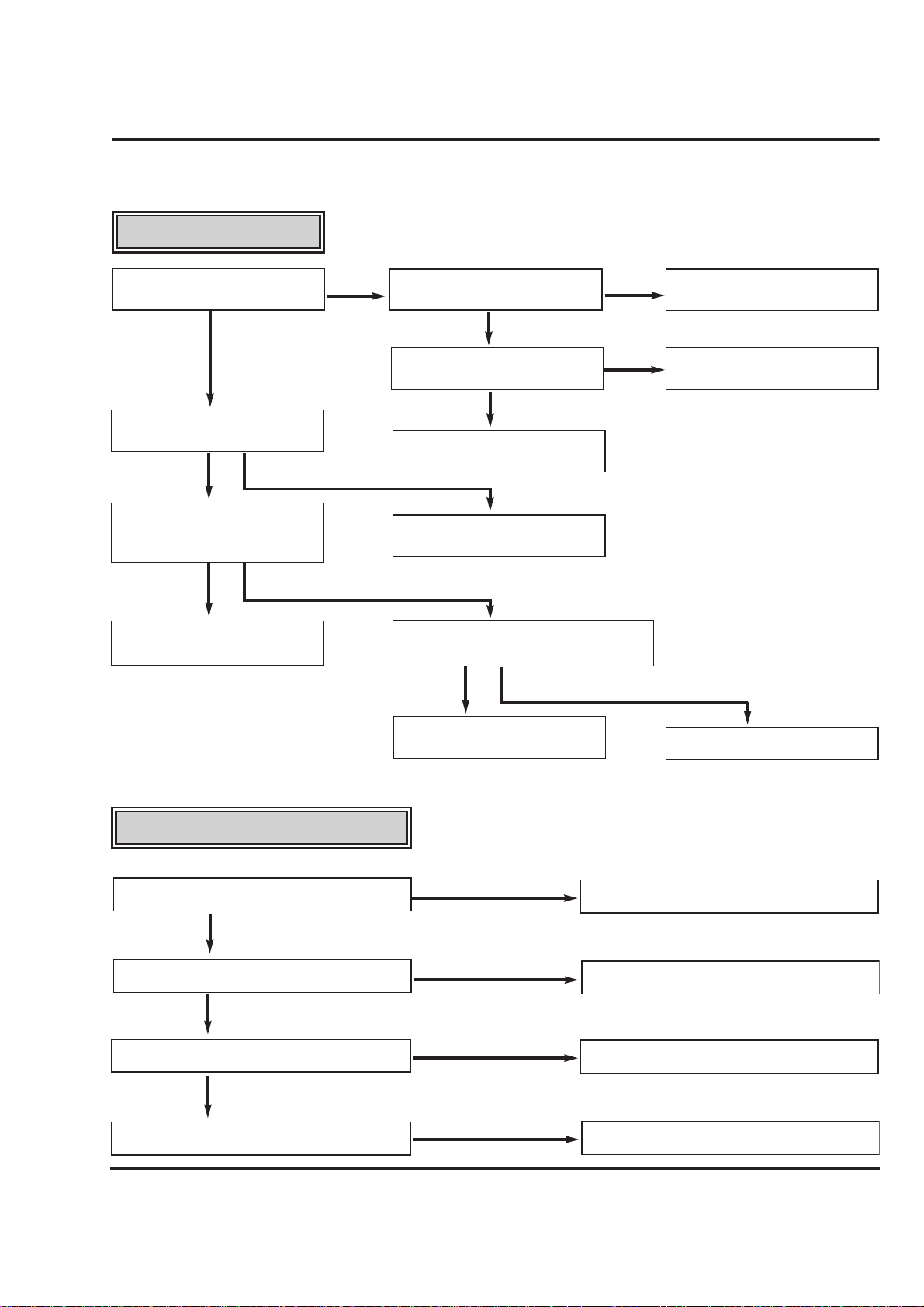
Auto REW doesn't work.
Is the output of END sensor
of supply side "H"?
“H”: more than 3.5V
“L”: less than 0.7V~1V
Is the voltage across IR LED
between 0.8~1.5V?
Replace LED.
Is the Vcc. voltage of End
sensor 5V?
Check the syscon power.
Replace End sensor.
Check syscon circuit.
NO
YES
YES
YES
NO
NO
NO
1.Deck Mechanism
A.
NO
NO
NO
No F/R modes.
Is the present mode,
F/R Mode?
Is the mode SW assembled
correctly (refer to Pages 4-14.)
Is the normal voltage supplied to
the Capstan Motor Vcc1, Vcc2.?
Does terminal voltage(Vctl) of
Capstan Motor supply side
more than 4V?
Check Servo, Power Circuits.
Replace the Capstan Motor.
Does the Capstan Motor rotate?
Do the T/Up, Supply Reel rotate?
Check syscon circuit.
YES
YES
YES
YES
YES
YES
B.
Page 28
4-27
MECHANISM TROUBLESHOOTING GUIDE
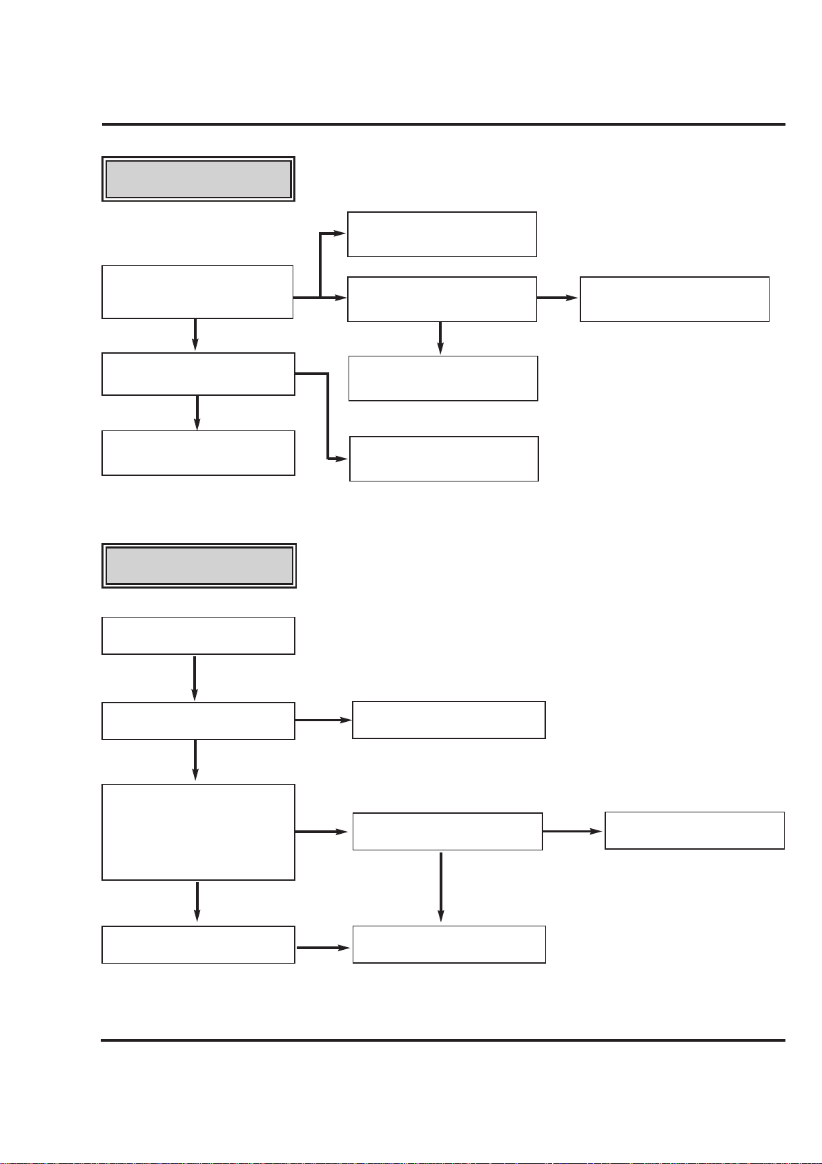
AUTO STOP.
(PLAY/CUE/REV)
Are there T/up and supply reel
pulses.
In Play/Cue/Rev is the pinch
roller in contact with the capstan
shaft.
Replace Reel Sensor.
Is the output of DFG, DPG OK?
Check aligment positions (page 4-
14) Check spring Pinch.
Replace Drum Motor.
Check Servo, Syscon.
Check the Syscon, µ-COM.
No cassette loading.
Insert the cassette.
Check Cassette Carry Assembly.
Is there variation for F/L S/W
Output?
(In Tape with REC Tab
“L”→“H”→“L”)
(In Tape without REC Tab
“L”→“H”→“L”→“H”)
Does the F/L S/W work normally?
Does the lever S/W work
normally.
Check Syscon Circuit.
Check Syscon Circuit.
Replace F/L S/W.
YES
YES
YES
YES
YES
YES
NO
NO
NO
NO
NO
NO
NO
YES
C.
D.
Page 29
4-28
MECHANISM TROUBLESHOOTING GUIDE
In PB mode Tape Presence
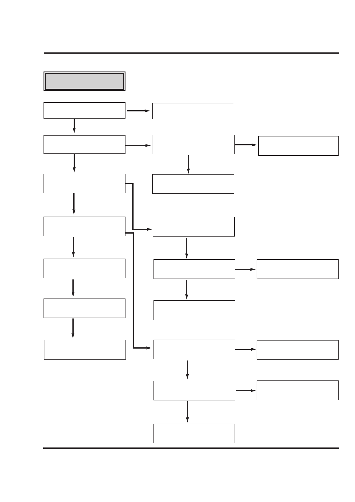
not sensed.
Is the Pinch Roller attached
to the Capstan Motor Shaft?
Check Alignment positions
(page 4-14)
Does the T/Up
Reel turn?
Replace the Belt.
Is the Belt ok?
Does the Drum
Motor turn?
Are there DPG,
DFG Pulses?
Are the T/Up Supply Reel Sensors
ok?
Check Syscon,
Circuit.
Check Syscon,
Circuit.
Check Servo, Syscon.
Does the Capstan Motor turn?
Is the terminal voltage
of the Drum Motor
more than 2.3V?
Replace the
Drum Motor.
Is the Vcc voltage of the Drum
Motor normal?
Check the clutch and the Idler
Assembly.
YES
YES
YES
YES
YES
YES
YES
YES
NO
NO
NO
NO
NO
Is the terminal voltage of Capstan
Motor supplied more than 4V?
Replace the
Capstan Motor.
Is the Voltage supplied to the Capstan
Motor Vcc1,Vcc2 each?
YES
YES
YES
Check Servo,
Power.
NO
NO
NO
E.
Page 30
4-29
MECHANISM TROUBLESHOOTING GUIDE
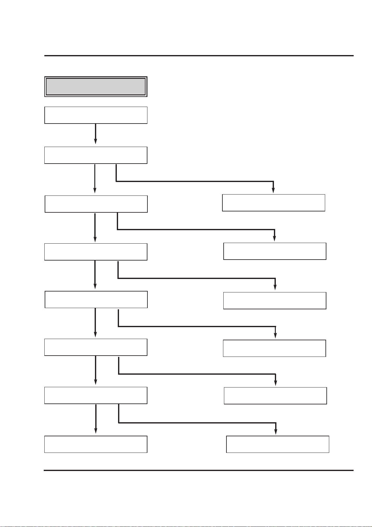
Cassette cannot be inserted.
Does the Lever Switch work?
Is the Lever Switch Spring
damaged or omitted?
Does the F/L switch work
normally?
Replace or add the
Lever Switch Spring.
Is the Vcc of Main P.C.Board
5V?
YES
YES
Check syscon circuit.
YES
Check power circuit.
NO
Is the voltage between cassette
switch and GND on Main
P.C.Board 5V??
YES
Is there a short circuit between cassette
switch and GND on main P.C.Board?
Remove the short circuit part or
Replace the main P.C.Board.
NO
Check Mode switch location and
syscon circuit.
Replace F/L Switch.
YES
NO
YES
NO
NO
Replace F/L Switch.
NO
NO
Cassette will not eject.
Does the L/D motor rotate in reverse?
Check L/D Motor or Drive IC.
Replace lever Switch.
Does the Lever Switch work?
YES
NO
NO
Does the Arm Assembly F/L work normally?
YES
NO
Does the Opener Door work?
YES
Replace Arm Assembly F/L.
Replace the Opener Door.
2. Front Loading Mechanism
A.
B.
Page 31
4-30
MECHANISM TROUBLESHOOTING GUIDE
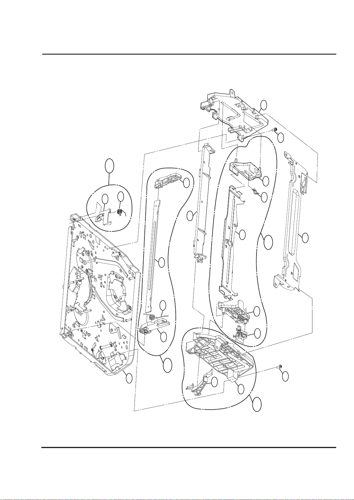
Cassette will not load.
Does the CST insert?
Does the opener Lid work?
Is the opener Door assembled correctly?
Replace the Opener Lid.
Replace the Arm Assembly F/L.
Check the power of L/D Motor.
Is the Holder Assembly Cassette
assembled correctly?
Replace the Rear Rack F/L.
Does the Gear Rack F/L work?
Does the Opener Door work?
Does the Arm Assembly F/L work?
Does the L/D Motor work?
Does the Holder Assembly Cassette
move the Arm Assembly F/L?
Replace the Front Loading
Mechanism Assembly.
YES
YES
YES
YES
NO
NO
NO
YES
NO
YES
NO
YES
NO
C.
Page 32
4-31
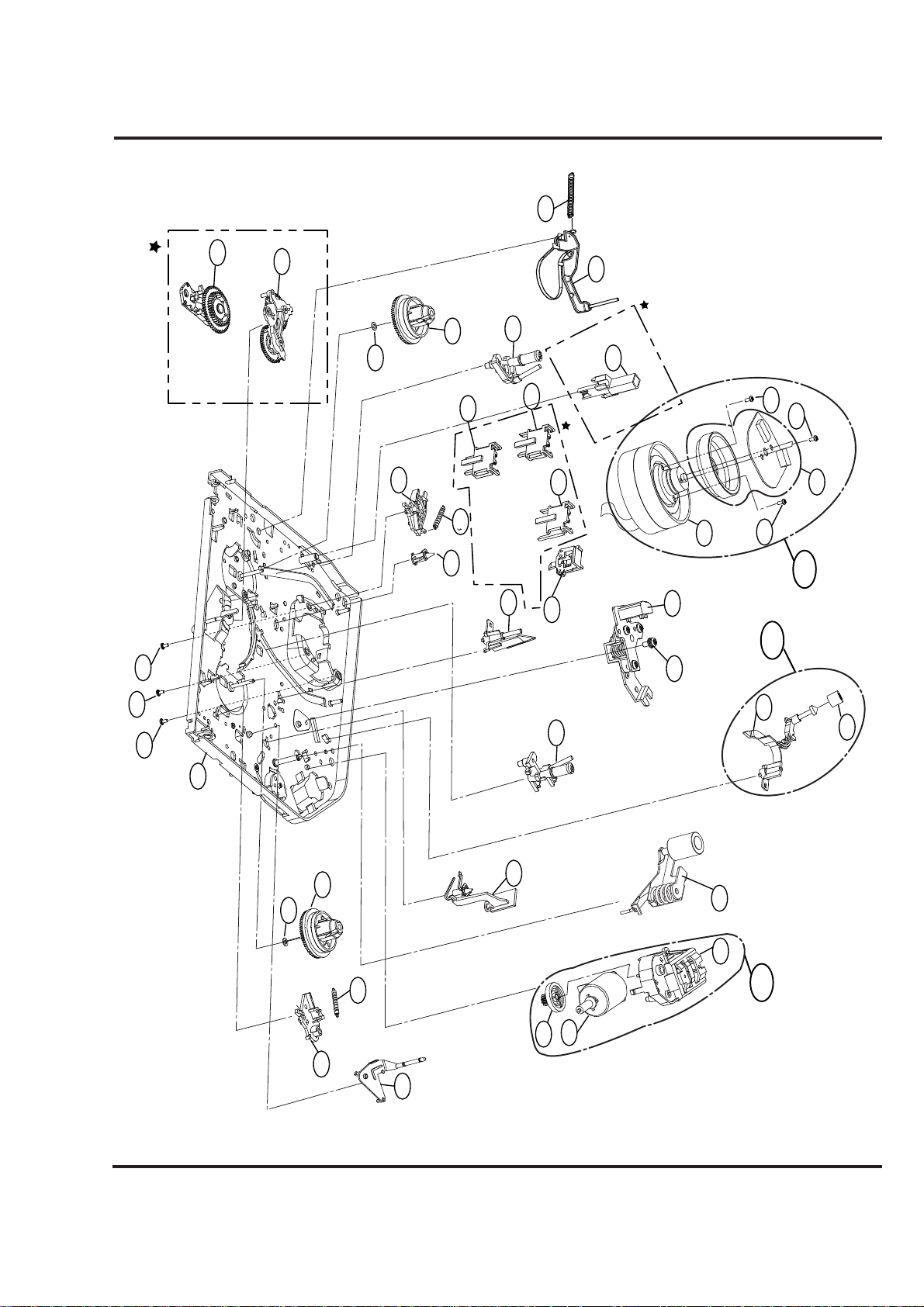
EXPLODED VIEWS
1. Front Loading Mechanism Section
A24
101
426
116
115
112
113
114
110
104
105
106
107
103
117
A21
100
032
A23
426
109
108
A22
Page 33
4-32
EXPLODED VIEWS
031
2. Moving Mechanism Section(1)
024
Optional Parts
024
(Only for Jog-shuttle Models)
(For Normal Models)
406
504
019
017
003
(Only for 2HD Models)
018
023
011
012
022
003
(Only for 4HD Mono Models)
014
Optional Parts
003
(Only for 4HD Hi-Fi Models)
004
Optional Parts
(Only for VCR Models)
001
016
409
401
401
002
401
A01
A03
406
406
032
504
028
021
020
009
015
027
013
007
006
029
025
A04
026
Page 34
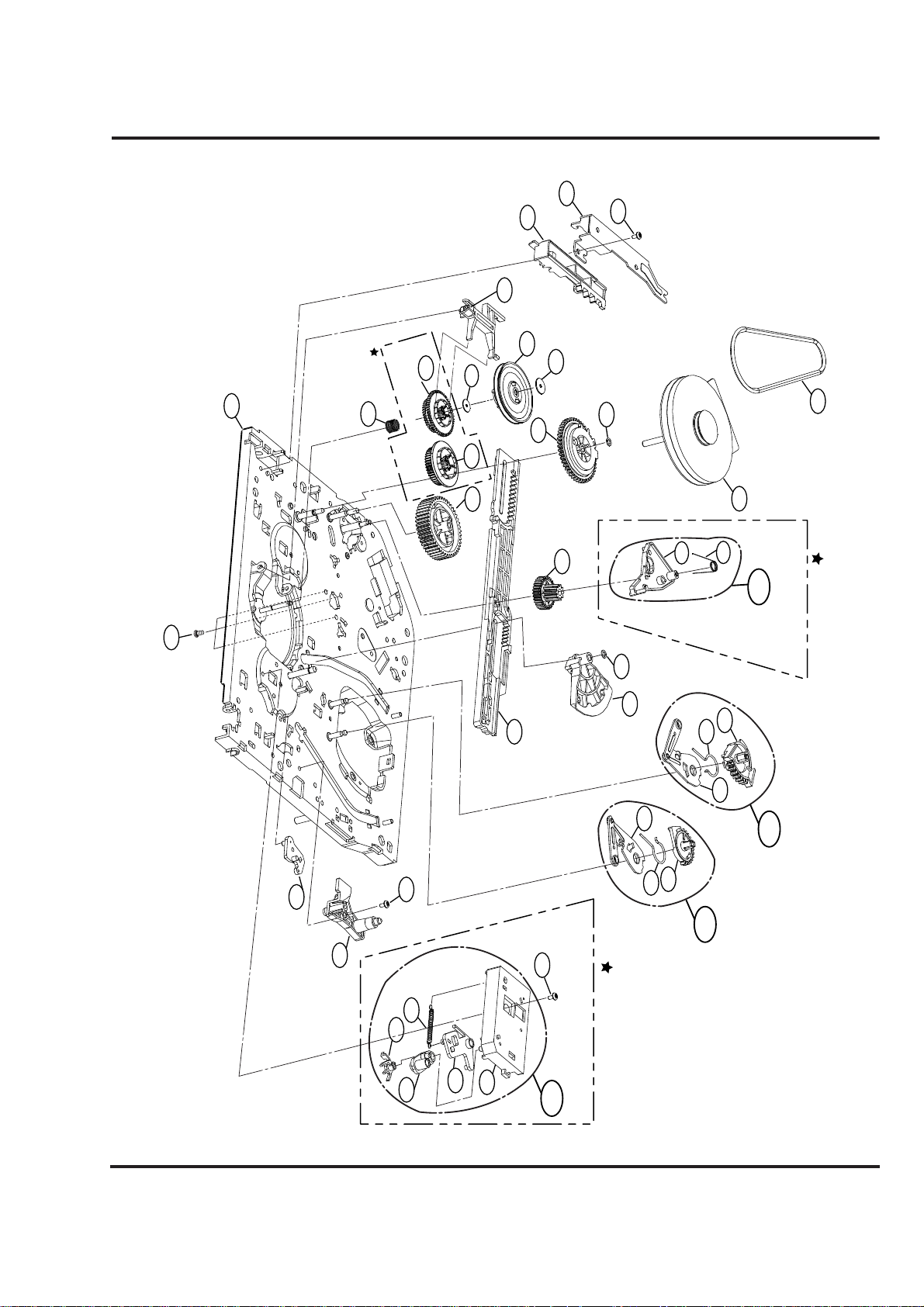
4-33
EXPLODED VIEWS
054
3. Moving Mechanism Section(2)
053
426
032
410
(Only for
Hi-Rewind Models)
Optional Parts
063
Nomal Models)
062
(Only for
519
062
056
060
077
061
055
517
057
518
518
064
058
066
059
067
052
051
(Only for 4HD Models)
A14
Optional Parts
078
079
075
426
074
076
072
071
070
(Only for Jog-Shuttle Models)
426
Optional Parts
A13
069
065
A11
068
A12
 Loading...