

Page 1

MFL34797007en-simp 9/8/08 3:15 PM Page 1
ST'_
t r
i
i
I LCD TV I PLASMA TV
OWNER'S MANUAL
LCD TV MODELS PLASMA TV MODEL
32LCSDC 32LCSOC 42PX8DC
32LCSDCS 32LC50CS 42PG65C
32LCSDCB 32LCSOCB 42PG60C
37LCSDC 32LX50C
37LC5DCB 32LXSOCS
37LCSDC1 37LC50C
42LC5DC 37LCSOCB
32LXSDC 42LBSOC
32LXSDCS 42LC50C
42LBSDC
Please read this manual
your set.
Retain it for
serial number of the set.
bed on the back cover and quote
service.
,rmation to your dealer when you require
\j/
P/NO : MFL34797007 (0809-REVIO)
Printed in Korea
i
i
Page 2
MFL34797007en-simp 9/8/08 3:15 PM Page 2
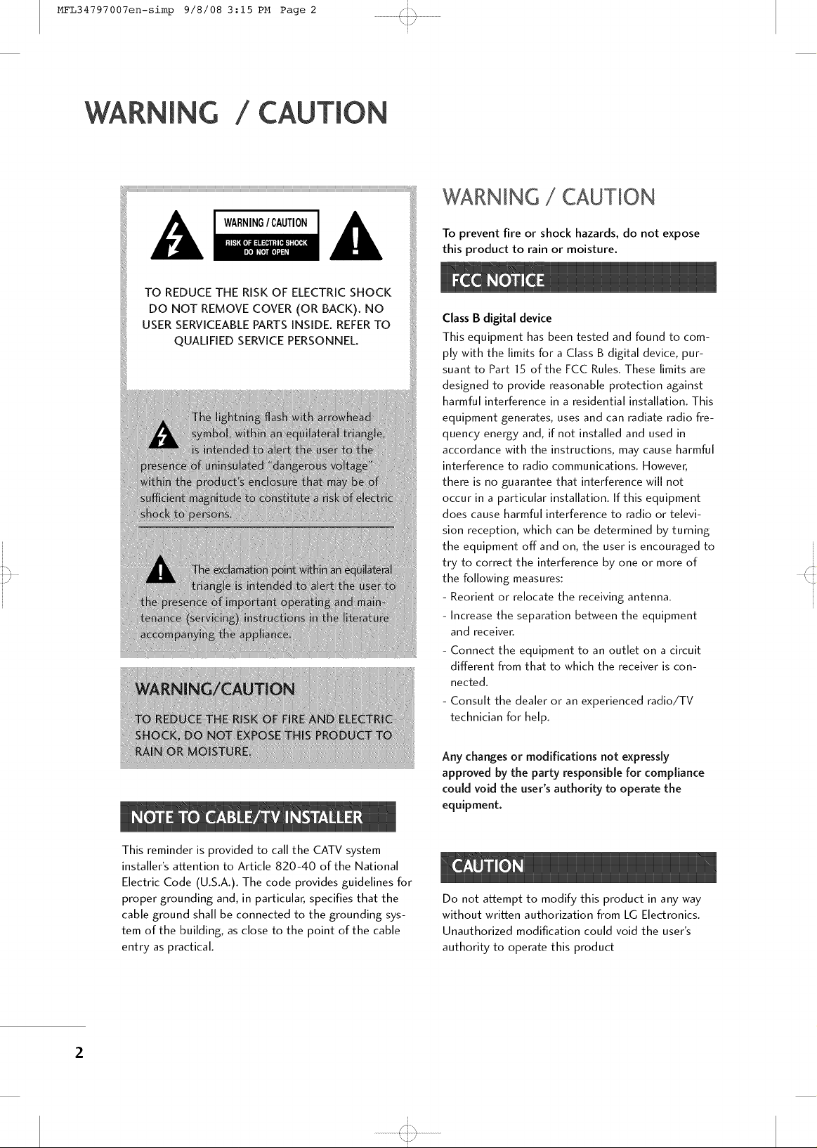
WARNING / CAUTION
TO REDUCE THE RISK OF ELECTRIC SHOCK
DO NOT REMOVE COVER (OR BACK). NO
USER SERVICEABLE PARTS INSIDE. REFER TO
QUALIFIED SERVICE PERSONNEL.
_Ta!i_ iiiii
rat u _ iiii
i
t r
i
WARNING / CAUTION
To prevent fire or shock hazards, do not expose
this product to rain or moisture.
Class B digital device
This equipment has been tested and found to com-
ply with the limits for a Class B digital device, pur-
suant to Part 15 of the FCC Rules. These limits are
designed to provide reasonable protection against
harmful interference in a residential installation. This
equipment generates, uses and can radiate radio fre-
quency energy and, if not installed and used in
accordance with the instructions, may cause harmful
interference to radio communications. However,
there is no guarantee that interference will not
occur in a particular installation. [f this equipment
does cause harmful interference to radio or televi-
sion reception, which can be determined by turning
the equipment off and on, the user is encouraged to
try to correct the interference by one or more of
the following measures:
- Reorient or relocate the receiving antenna.
- increase the separation between the equipment
and receiver.
- Connect the equipment to an outlet on a circuit
different from that to which the receiver is con-
nected.
- Consult the dealer or an experienced radio/TV
technician for help.
Any changes or modifications not expressly
approved by the party responsible for compliance
could void the user's authority to operate the
equipment.
This reminder is provided to call the CATV system
installer's attention to Article 820-40 of the National
Electric Code (U.S.A.). The code provides guidelines for
proper grounding and, in particular, specifies that the
cable ground shall be connected to the grounding sys-
tem of the building, as close to the point of the cable
entry as practical.
Do not attempt to modify this product in any way
without written authorization from LG Electronics.
Unauthorized modification could void the user's
authority to operate this product
2
i
\j/
i
Page 3
MFL34797007en-simp 9/8/08 3:15 PM Page 3
SAFETYINSTRUCTIONS
IMPORTANT SAFETY INSTRUCTIONS
Read these instructions.
Keep these instructions.
Heed all warnings.
Follow all instructions.
S]%
t r
i
i
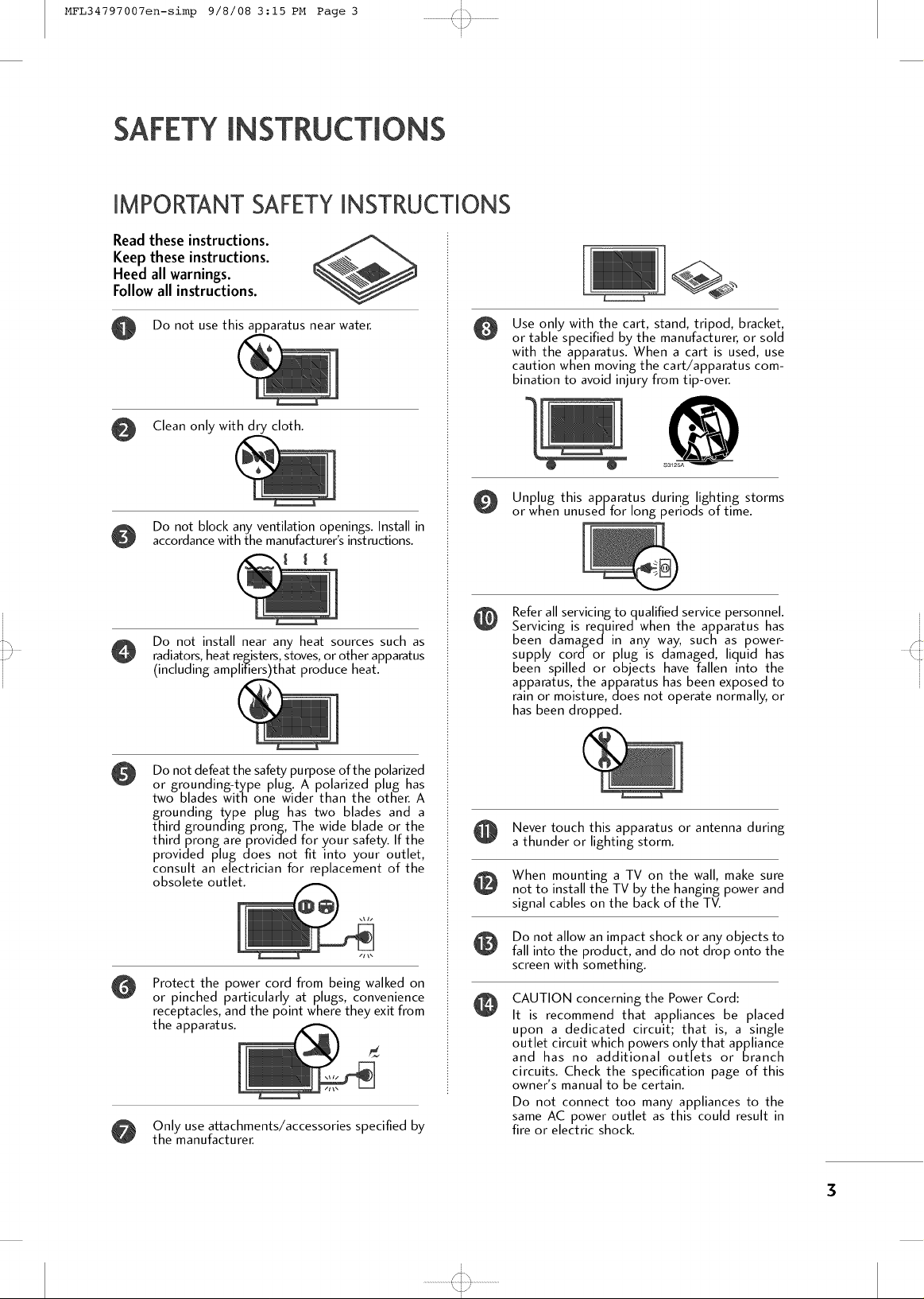
Do not use this apparatus near water.
Clean only with dry cloth.
Do not block any ventilation openings. Install in
accordance with the manufacturer's instructions.
I I I
Do not install near any heat sources such as
radiators, heat registers, stoves, or other apparatus
(including amplifiers)that produce heat.
Do not defeat the safety purpose of the polarized
@
or grounding-type plug. A polarized plug has
two blades with one wider than the other. A
grounding type plug has two blades and a
third grounding prong, The wide blade or the
third prong are provided for your safety. If the
provided plug does not fit into your outlet,
consult an electrician for replacement of the
obsolete outlet.
Use only with the cart, stand, tripod, bracket,
@
or table specified by the manufacturer, or sold
with the apparatus. When a cart is used, use
caution when moving the cart/apparatus com-
bination to avoid injury from tip-over.
O Unplug this apparatus during lighting storms
or when unusedfor long periods of time.
Refer all servicing to qualified service personnel.
@
Servicing is required when the apparatus has
been damaged in any way, such as power-
supply cord or plug is damaged, liquid has
been spilled or objects have fallen into the
apparatus, the apparatus has been exposed to
rain or moisture, does not operate normally, or
has been dropped.
Never touch this apparatus or antenna during
a thunder or lighting storm.
When mounting a TV on the wall, make sure
not to install the TV by the hanging power and
signal cables on the back of the TV.
Protect the power cord from being walked on
@
or pinched particularly at plugs, convenience
receptacles, and the point where they exit from
the apparatus.
Only use at2achments/accessories specified by
the manufacturer.
Do not allow an impact shock or any objects to
fall into the product, and do not drop onto the
screen with something.
CAUTION concerning the Power Cord:
It is recommend that appliances be placed
upon a dedicated circuit; that is, a single
outlet circuit which powers only that appliance
and has no additional outlets or branch
circuits. Check the specification page of this
owner's manual to be certain.
Do not connect too many appliances to the
same AC power outlet as this could result in
fire or electric shock.
i
........................4:,,,,,_.,,,,,I.........................
\j/
i
3
Page 4
MFL34797007en-simp 9/8/08 3:15 PM Page 4
SAFETYINSTRUCTIONS
i
t r i
i
Do not overload wall outlets. Overloaded wall
outlets, loose or damaged wall outlets, extension
cords, frayed power cords, or damaged or
cracked wire insulation are dangerous. Any of
these conditions could result in electric shock
or fire. Periodically examine the cord of your
appliance, and if its appearance indicates damage
or deterioration, unplug it, discontinue use of
the appliance, and have the cord replaced with
an exact replacement part by an authorized
servicer. Protect the power cord from physical
or mechanical abuse, such as being twisted,
kinked, pinched, closed in a door, or walked
upon. Payparticular attention to plugs, wall
outlets, and the point where the cord exits the
appliance.
Do not make the TV with the power cord
plugged in. Do not use a damaged or loose
power cord. Be sure do grasp the plug when
unplugging the power cor& Do not pulFon the
power cora to unplug the TV.
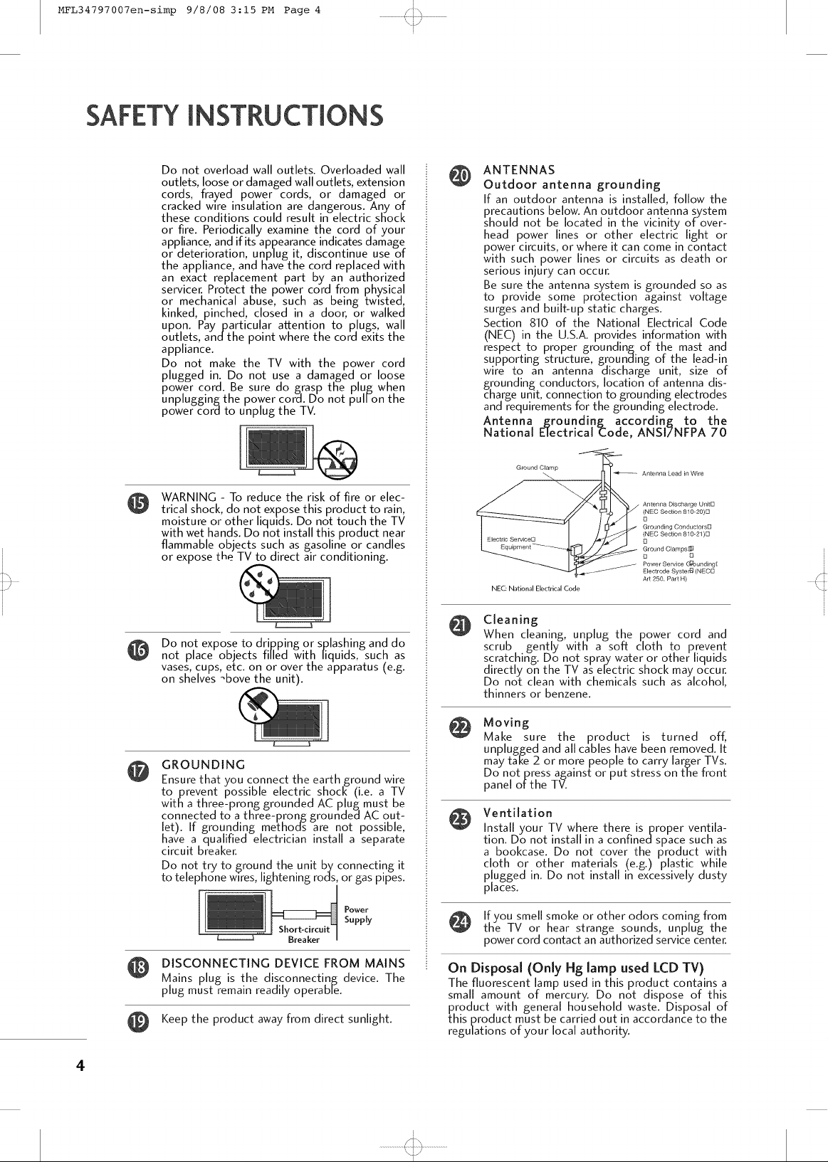
WARNING - To reduce the risk of fire or elec-
@
trical shock, do not expose this product to rain,
moisture or other liquids. Do not touch the TV
with wet hands. Do not install this product near
flammable objects such as gasoline or candles
or expose the TV to direct air conditioning.
ANTENNAS
@
Outdoor antenna grounding
If an outdoor antenna is installed, follow the
precautions below. An outdoor antenna system
should not be located in the vicinity of over-
head power lines or other electric light or
power circuits, or where it can come in contact
with such. power lines or circuits as death or
serious Injury can occur.
Be sure the antenna system is grounded so as
to provide some protection against voltage
surges and built-up static charges.
Section 810 of the National Electrical Code
(NEC) in the U.S.A. provides information with
respect to proper grounding of the mast and
supporting structure, grounaing of the lead-in
wire to an antenna discharge unit, size of
grounding conductors, location of antenna dis-
charge unit, connection to grounding electrodes
and requirements for the grounding electrode.
Antenna _roundinf_ according to the
National Electrical _ode, ANSI7NFPA 70
Ground Clamp Antenna Lead in Wire
(NEC Section 810-20)D
D
Grounding Conductors[3
(NEC Section 810-21)[3
_ Antenna Discharge UnitD
. Electrode Syste ri9 (NECD
NEC: National Electrical Code
D
Ground Clam ps[_]
D D
Power Service G_ounding[
Art 250, Part H)
Do not expose to dripping or splashing and
not place objects filled with liquids, such _
vases, cups, etc. on or over the apparatus (e.g.
on shelves _bove the unit).
GROUNDING
@
Ensure that you connect the earth ground wire
to prevent possible electric shocl< (i.e. a TV
with a three-prong grounded AC plug must be
connected to a three-prong groundea AC out-
let). If grounding methods are not possible,
have a qualified electrician install a separate
circuit breaker.
Do not try to ground the unit by connecting it
to telephone wires, lightening rods, or gas pipes.
DISCONNECTING DEVICE FROM MAINS
Mains plug is the disconnecting device. The
plug must remain readily operable.
Keep the product away from direct sunlight.
Supply
Power
(o
Cleaning
@
When cleaning, unplug the power cord and
scrub gently with a soft cloth to prevent
scratching. Do not spray water or other liquids
directly on the TV as electric shock may occur.
Do not clean with chemicals such as alcohol,
thinners or benzene.
Moving
@
Make sure the product is turned off,
unplugged and all cables have been removed. It
may take 2 or more people to carry larger TVs.
Do not press against or put stress on the front
panel of the TV.
Ventilation
@
Install your TV where there is proper ventila-
tion. Do not install in a confinedspace such as
a bookcase. Do not cover the product with
cloth or other materials (e.g.) plastic while
plugged in. Do not install in excessively dusty
places.
If you smell smoke or other odors coming from
the TV or hear strange sounds, unplug the
power cord contact an authorized service center.
On Disposal (Only Hg lamp used LCD TV)
The fluorescent lamp used in this product contains a
small amount of mercury. Do not dispose of this
product with general household waste. Disposal of
this product must be carried out in accordance to the
regulations of your local authority.
4
i
........................4:+,,_-,,,I.........................
\j./
i
Page 5
MFL34797007en-simp 9/8/08 3:15 PM Page 5
WARNING / CAUTION ............................ 2
i
t r
i
SAFETY INSTRUCTIONS ..........................3
HD Receiver Setup ......................................... 21
DVD Setup ..................................................... 22
VCR Setup ..................................................... 23
PC Setup ........................................................ 24
Accessories ...................................................... 6
Front Panel Information ...................................... 7
Back Panel Information ...................................... 9
Stand Installation ............................................. 11
Remote Control Functions ................................ 12
Back Cover for Wire Arrangement ..................... 14
Protection Cover ............................................. 16
Attaching the TV to a Wall ............................... 17
Swivel Stand .................................................... 17
Attaching the TV to a desk ............................... 18
VESA Wall Mounting ........................................ 19
Desktop Pedestal Installation ........................... 19
Antenna or Cable Connection .......................... 20
Turning On the TV .......................................... 27
Channel Selection ........................................... 27
Volume Adjustment ......................................... 27
Channel Setup ................................................ 28
On-Screen Menus Selection ............................ 29
Troubleshooting .............................................. 32
Maintenance ................................................... 34
Product Specifications ..................................... 35
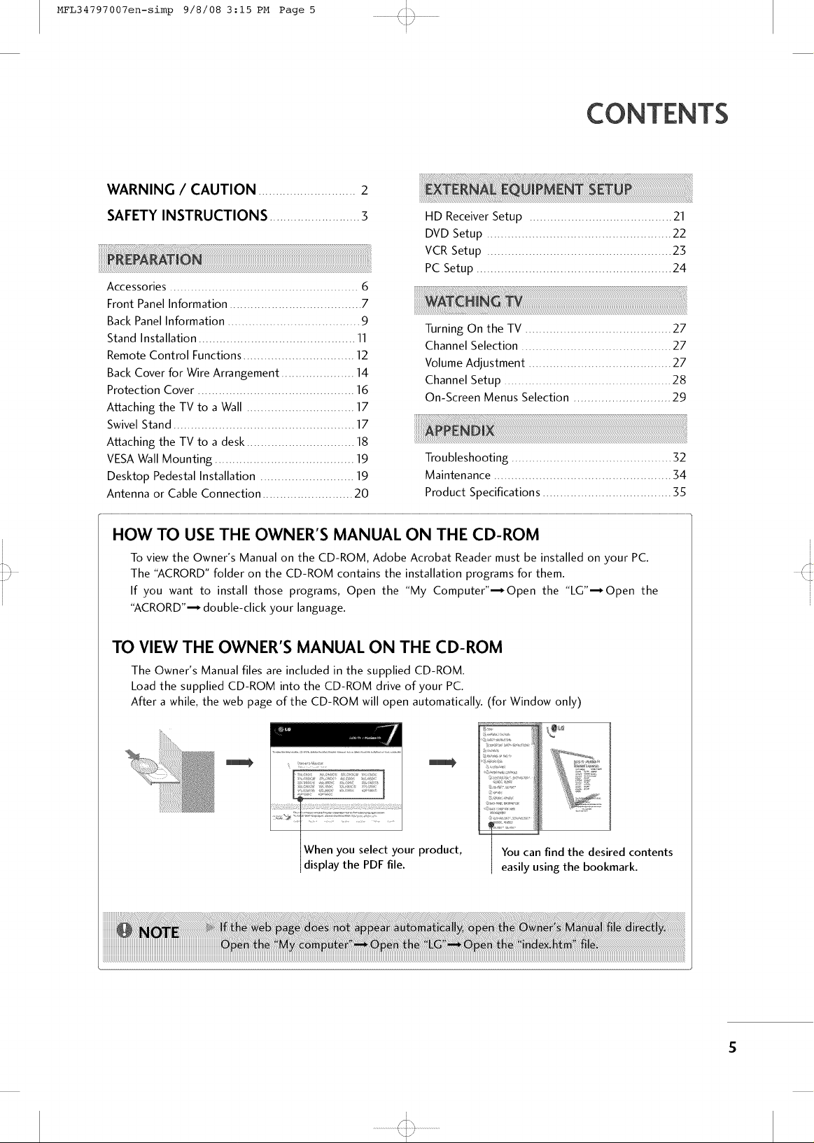
HOW TO USE THE OWNER'S MANUAL ON THE CD-ROM
To view the Owner's Manual on the CD-ROM, Adobe Acrobat Reader must be installed on your PC.
The "ACRORD" folder on the CD-ROM contains the installation programs for them.
If you want to install those programs, Open the "My Computer"--_Open the "LG"--_Open the
"ACRORD"--_ double-click your language.
TO VIEW THE OWNER'S MANUAL ON THE CD-ROM
The Owner's Manual files are included in the supplied CD-ROM.
Load the supplied CD-ROM into the CD-ROM drive of your PC.
After a while, the web page of the CD-ROM will open automatically. (for Window only)
iilZ:++++ii
7,7 ;,
........... +
:tL{...... 7
You can find the desired contents
easily using the bookmark.
i
........................p,+.,,,,,,;.........................
\j/
i
Page 6
MFL34797007en-simp 9/8/08 3:15 PM Page 6
PREPARATION
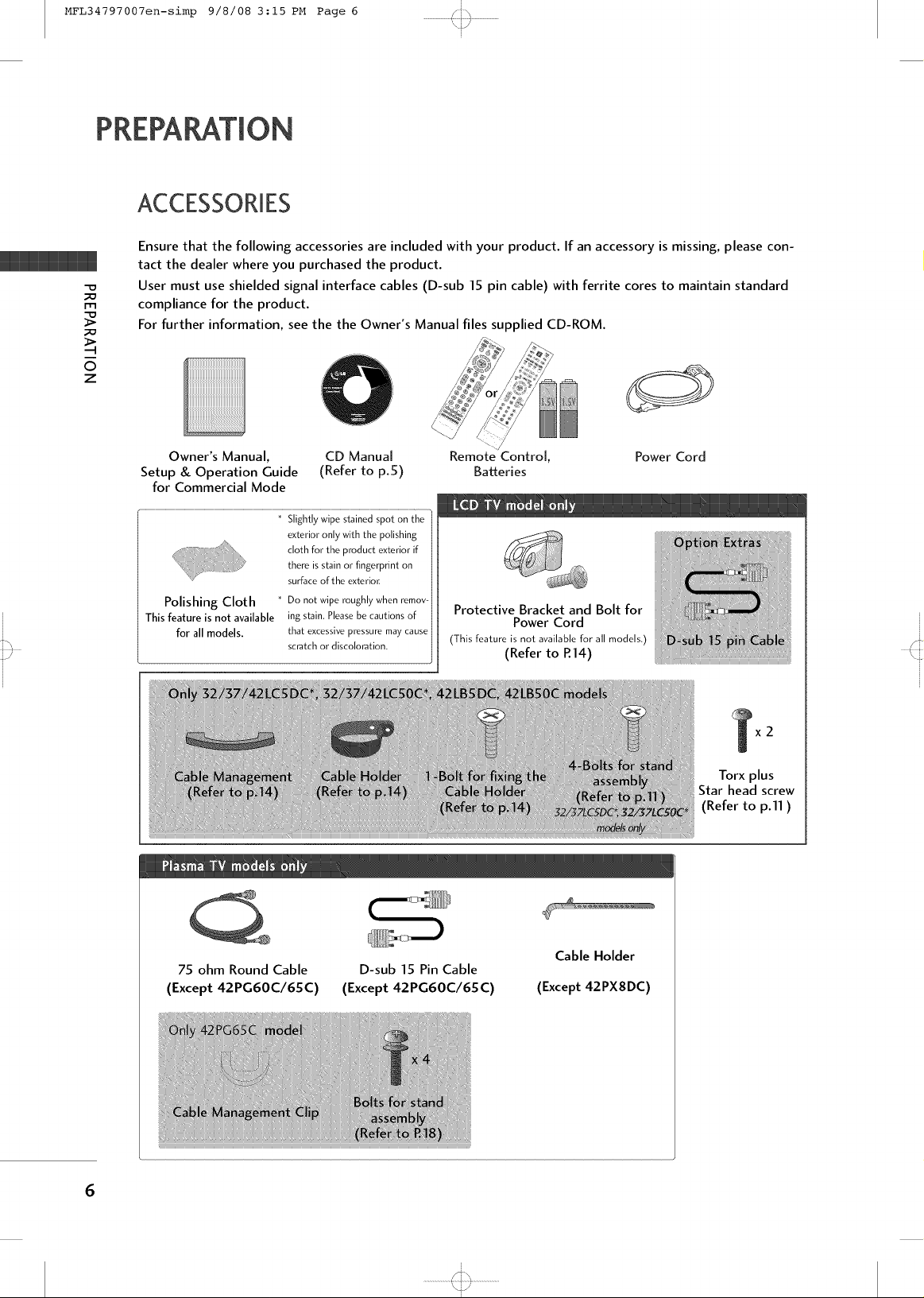
ACCESSORMES
Ensure that the following accessories are included with your product. If an accessory is missing, please con-
tact the dealer where you purchased the product.
User must use shielded signal interface cables (D-sub 15 pin cable) with ferrite cores to maintain standard
compliance for the product.
For further information, see the the Owner's Manual files supplied CD-ROM.
0
z
ST'_
t r i
i
i
Owner's Manual, CD Manual
Setup & Operation Guide (Refer to p.5)
for Commercial Mode
....................................................................................................................................................................................; 77i_{,y77_7stZZ77o{o_Z7
exterior only with the polishing
cloth for the product exterior if
there is stain or fingerprint on
surface of the exterion
Polishing Cloth
This feature is not available
for all models.
I1iiii!iiiiii_
* Do not wipe roughly when remov-
ing stain. Please be cautions of
that excessive pressure may cause
scratch or discoloration.
Remote Control, Power Cord
Batteries
Protective Bracket and Bolt for
Power Cord
(This feature is not available for all models.)
(Refer to R14)
Torx plus
Star head screw
(Refer to p.ll )
75 ohm Round Cable
(Except 42PG60C/6SC)
D-sub 15 Pin Cable
(Except 42PG60C/6SC)
(Except 42PXSDC)
6
i
........................4:--,_.--,I.........................
\j/
i
Cable Holder
Page 7
MFL34797007en-simp 9/8/08 3:15 PM Page 7
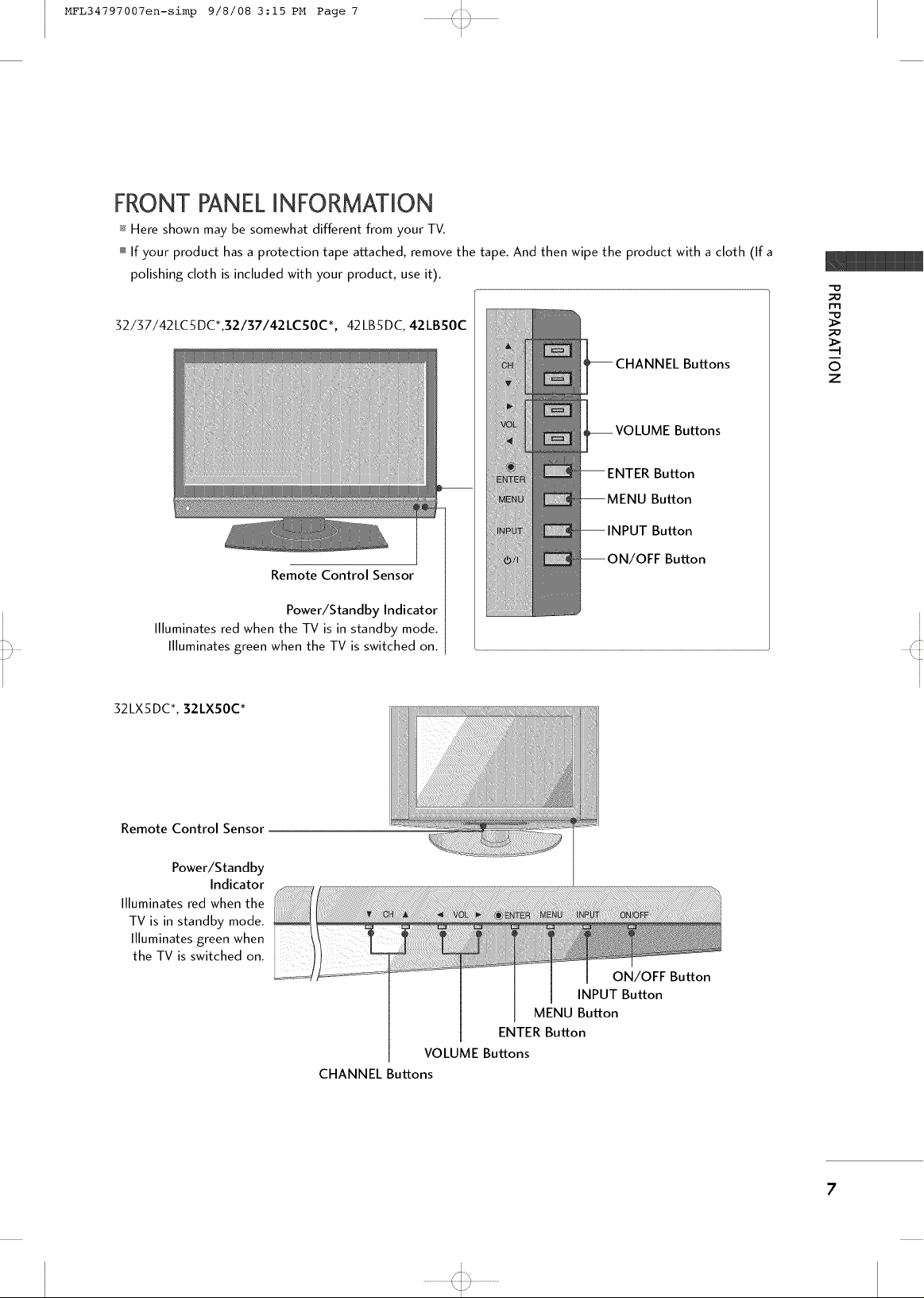
FRONT PANELINFORMATION
+ Here shown may be somewhat different from your TV.
mIf your product has a protection tape attached, remove the tape. And then wipe the product with a cloth (Ifa
polishing cloth is included with your product, use it).
32/37/42LC5DC*,32/37/42LCSOC*, 42LB5DC, 42LB50C
S]%
t r
i
i
-D
Remote Control Sensor
Power/Standby Indicator
Illuminates red when the TV is in standby mode.
Illuminates green when the TV is switched on.
32LX5DC*, 32LX50C*
Buttons
Buttons
Button
Button
Button
IOFF Button
©
z
Remote Control Sensor
Power/Standby
Indicator
Illuminates red when the
TV is in standby mode.
Illuminates green when
the TV is switched on.
CHANNEL Buttons
ENTER Button
VOLUME Buttons
i
\j/
i
ON/OFF Button
INPUT Button
MENU Button
Page 8
MFL34797007en-simp 9/8/08 3:15 PM Page 8
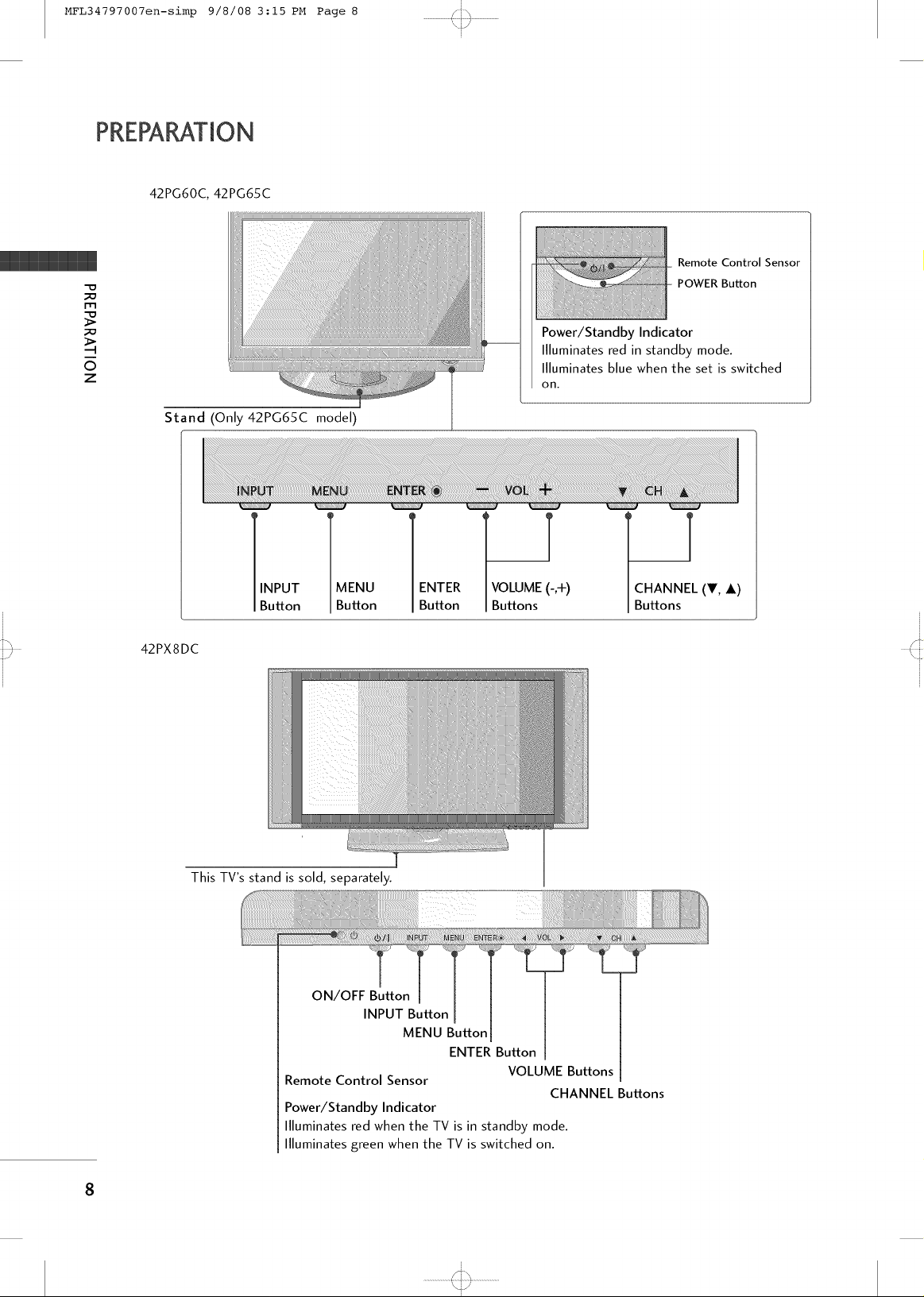
42PG60C, 42PG65C
m
O
z
Stand (Only42PG65C model)
S]%
t r
i
i
Remote Control Sensor
POWER Button
Power/Standby Indicator
Illuminates red in standby mode.
Illuminates blue when the set is switched
on.
42PX8DC
INPUT
Button
This TV's stand is sold, separately.
Remote Control Sensor
Power/Standby Indicator
llluminates red when the TV is in standby mode.
llluminates green when the TV is switched on.
MENU
Button
ON/OFF Button
INPUT Button
ENTER
Button
MENU Button
ENTER Button
1
VOLUME (-,+)
Buttons
VOLUME Buttons
CHANNEL Buttons
1
CHANNEL (_V, i)
Buttons
8
i
........................4:,,,,,_.,,,,,I.........................
\j/
i
Page 9
MFL34797007en-simp 9/8/08 3:15 PM Page 9
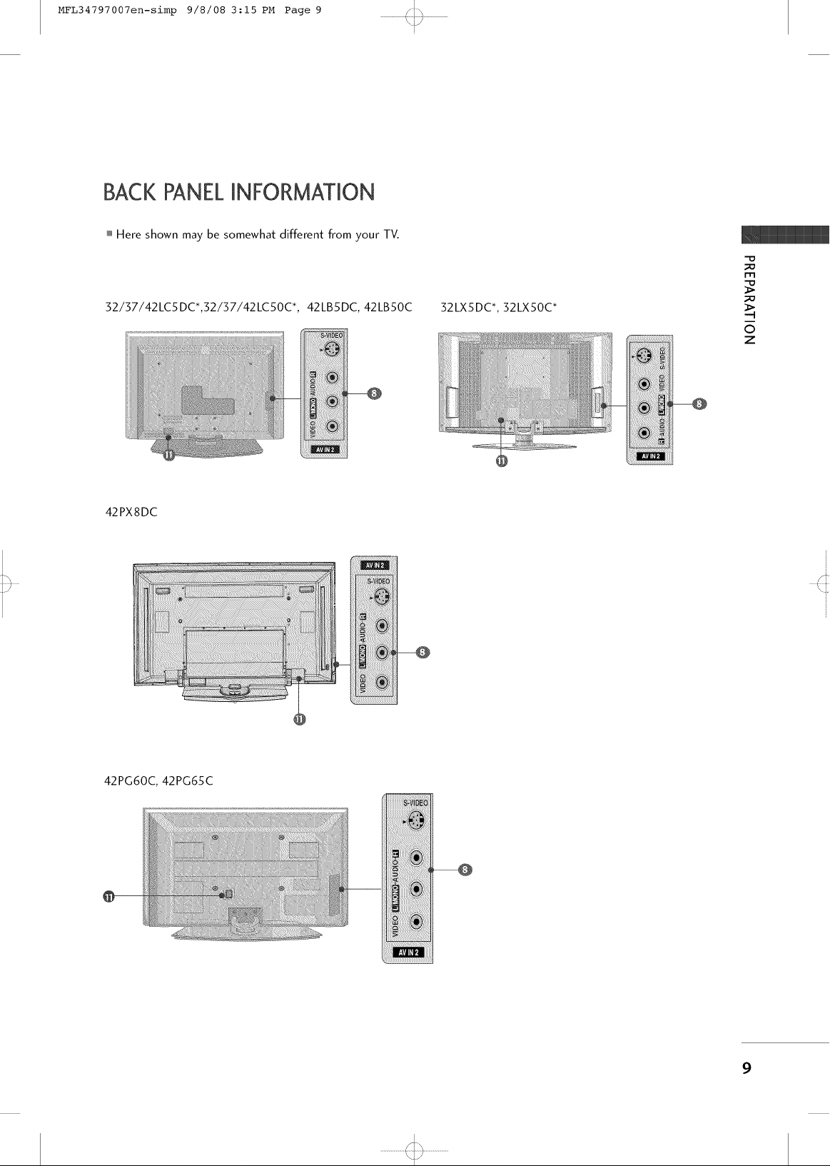
BACK PANELINFORMATION
Here shown may be somewhat different from your TV.
ST'_
t r
i
i
m
52/57/42LC5 DC*,52/57/42LCSOC +,
42PX8DC
42LBSDC, 42LB50C 52LXSDC +, 52LX50C +
©
z
42PG60C, 42PG65C
777777777777777i/iD£_
;;;;;;;7;7;7;717_!7777
i
S\
........................4:,,,,,_.,,,,,I.........................
\j/
i
9
Page 10
MFL34797007en-simp 9/8/08 3:15 PM Page i0 /ih
PREPARATION
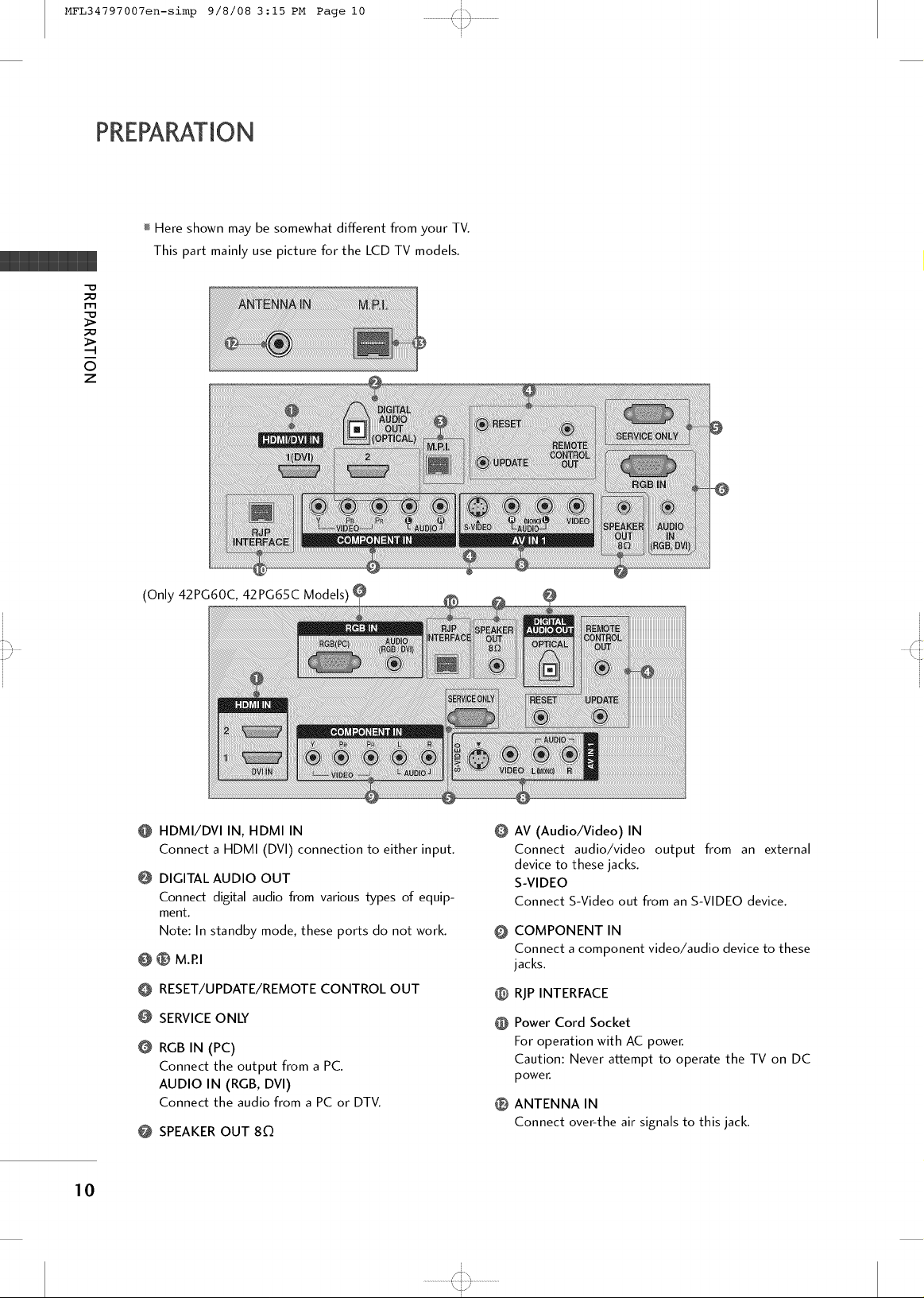
Here shown may be somewhat different from your TV.
This part mainly use picture for the LCD TV models.
m
O
z
J
(Only 42PG60C, 42PG65C Models) O
@
HDMI/DVI IN, HDMI IN
Connect a HDMI (DVI) connection to either input.
@
DIGITAL AUDIO OUT
Connect digital audio from various types of equip-
ment.
Note: In standby mode, these ports do not work.
® M.P.I
O
RESET/UPDATE/REMOTE CONTROL OUT
O
O
SERVICEONLY
O
RGB IN (PC)
Connect the output from a PC.
AUDIO IN (RGB, DVI)
Connect the audio from a PC or DTV.
@ SPEAKER OUT 80
@
AV (Audio/Video) IN
Connect audio/video output from an external
device to these jacks.
S-VIDEO
Connect S-Video out from an S-VIDEO device.
COMPONENT IN
@
Connect a component video/audio device to these
jacks.
@
RJP INTERFACE
Power Cord Socket
@
For operation with AC power.
Caution: Never at:kempt to operate the TV on DC
power.
ANTENNA IN
®
Connect over-the air signals to this jack.
10
i
........................4:,,,,,_-,,,I.........................
\jJ
i
Page 11
MFL34797007en-simp 9/8/08 3:15 PM Page ii
STAND INSTALLATION
ST'_
t r
i
i
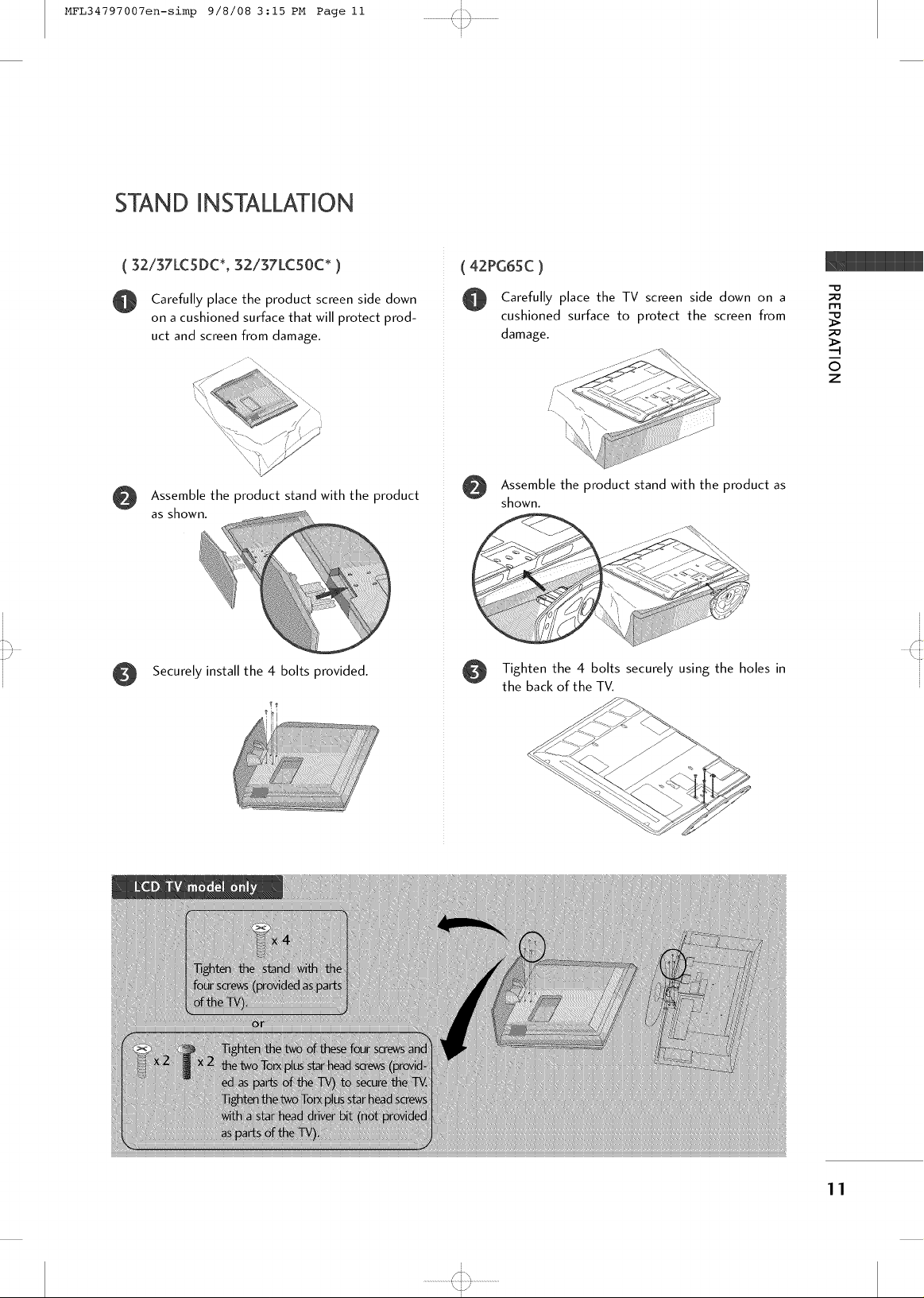
( 32137LC5DC*, 32/37LC50C* )
Carefully place the product screen side down
on a cushioned surface that will protect prod-
uct and screen from damage.
i
Assemble the product stand with the product
as shown.
Securely install the 4 bolts provided.
( 42PG65C )
Carefully place the TV screen side down on a
cushioned surface to protect the screen from
damage.
"\\
Assemble the product stand with the product as
@
shown.
_ _ ,,,_S_!:!I
Tighten the 4 bolts securely using the holes in
the back of the TV.
-D
m
©
z
\j/
11
i
i
Page 12

MFL34797007en-simp 9/8/08 3:15 PM Page 12 /ih
PREPARATION
REMOTECONTROL FUNCTMONS
[
m
O
z
When using the remote control, aim it at the remote control sensor on the TV.
POWER
TV INPUT
- _ + Adjusts brightness on screen.
PIP CH +i-
PIP INPUT
EZ PIC environment.
EZ SOUND Selects the factory preset sound for type of program.
Turns your TV or any other programmed equipment on
or off, depending on mode.
In AV 1-2, Component, RGB, HDMI1/DVI, and HDMI2
input sources, screen returns to the last TV channel.
INPUT
External input modes rotate in regular sequence: TV, AV1 -
2, Component, RGB, HDMI1/DVI and HDMI2.
MULTI Selects: RGB,HDMI1/DVI, HDMI2 and Component input
sources.
PIP
Switchesthe sub picture Double Window or off mode.
Changes the PIP channel.
Select the connected input source for the sub-picture.
Selects the factory preset picture depend on the viewing
POWER
RATIO
12
SWAP(or PIP
SWAP) Exchange the main/sub images.
VCRiDVD Control video cassette recorders or DVD players.
control buttons
NUMBER button
-- (DASH) Used to enter a program number for multiple program
FLASH BACK Tune to the last channel viewed.
channels such as 2-1,2-2, etc.
[
\j/
i
Page 13

MFL34797007en-simp 9/8/08 3:15 PM Page 13
(Only 42PG60C, 42PG65C models)
RATIO CC
THUMBSTICK Navigate the on-screen menus and adjust the system set-
(Up/Down/Left tings to your preference.
/Right/ENTER)
i
ST'_
t r i
i
MODE Select the remote's operating mode: TV, DVD, VCR (or
STB).
RATIO Change the aspect ratio.
CC Select a closed caption.
-D
m
©
z
EXIT(or
RETURN)
MENU
VOLUME UP
Clears all on-screen displays and returns to TV viewing
from any menu.
Displays the main menu.
INFO
Display information at the top of the screen.
Increase/decrease the sound level.
/DOWN
TIMER
CHANNEL
UP/DOWN
UP/DOWN
Select the amount of time before your TV turns off auto-
matically.
MUTE Switch the sound on or off.
Select available channels.
PAGE
Move from one full set of screen information to the next one.
i
........................4:,,,,,_-,,,I.........................
\j/
i
13
Page 14

MFL34797007en-simp 9/8/08 3:15 PM Page 14 /ih
PREPARATION
BACK COVERFORWMREARRANGEMENT
mHere shown may be somewhat different from your TV.
(This feature is not available for all models.)
m
O onnect the cables as necessary.
To connect an additional equipment, see the EXTERNAL
O
z
EQUIPMENT SETUP section.
Secure the power cable with the PROTECTIVE
BRACKET and the screw as shown. It will help prevent
the power cable from being removed by accident.
J
PROTECTIVE BRACKET
Install the CABLE HOLDER as shown.
Install the CABLE MANAGEMENT as shown.
CABLE HOLDER
CABLE MANAGEMENT
BOLT
14
i
........................4:+,,_.,,,,,,j.........................
\jJ
i
Page 15

MFL34797007en-simp 9/8/08 3:15 PM Page 15 /ih
BACK COVERFORWMREARRANGEMENT
Here shown may be somewhat different from your TV.
J
(This feature is not available for all models.)
O o separate the CABLE HOLDER, loosen the bolt
installed the set.
Connect the cables as necessary.
O
To connect an additional equipment, see the EXTERNAL
EQUIPMENT SETUP section.
Secure the power cable with the PROTECTIVE
BRACKET and the screw as shown. It will help prevent
the power cable from being removed by accident.
Install the CABLE HOLDER as shown.
O
m
_o
©
z
\PROTECTIVE BRACKET
/ \
BOLT CABLE
HOLDER
15
i
........................4:,,,,,_.,,,,,I.........................
\jJ
i
Page 16

MFL34797007en-simp 9/8/08 3:15 PM Page 16
PREPARATION
S]%
t r
i
i
42PX8DC
I-I"1
O
z
Hold the CABLE MANAGEMENT with both
hands and pull it as shown.
Connect the cables as necessary.
O
To connect an additional equipment, see the
EXTERNAL EQUIPMENT SETUP section.
42PG60C, 42PG65C
Connect the cables as necessary.
To connect additional equipment, see the
EXTERNAL EQUIPMENT SETUP section.
Install the CABLE MANAGEMENT CLIP as
shown. (Except 42PG60C model)
If your TV has CABLE HOLDER, fix it as shown
and bundle the cables.
Install the CABLE MANAGEMENT as shown.
@
:ABLE MANAGEMENT CABLE HOLDER
CLIP
How to remove the
CABLE MANAGEMENT CLIP
(Except 42PG60C model)
First, press the cable management. Hold the
CABLE MANAGEMENT CLIP with both
hands and pull it upward.
16
i
........................4:,,,,,_.,,,,,I.........................
\j/
i
Page 17

MFL34797007en-simp 9/8/08 3:15 PM Page 17 /ih
ATTACHING THE TV TO A WALL
I This feature is not available for all models.
We recommend that you set up the TV close to a wall so it cannot fall over if pushed backwards.
Additionally, we recommend that the TV be attached to a wall so it cannot be pulled in a forward direction,
potentially causing injury or damaging the product.
Caution: Please make sure that children don't climb on or hang from the TV.
[
-D
m
©
z
i Insert the TV brackets (or eye-bolts) and bolts to tighten the product to the wall as shown in the picture.
*If your product has the bolts in the eye-bolts position before inserting the eye-bolts, loosen the bolts.
Secure the wall brackets with the bolts (not provided as parts of the product, must purchase separately) on
the wall. Match the height of the bracket that is mounted on the wall to the holes in the product.
Ensure the eye-bolts or brackets are tightened securely.
I Use a sturdy rope (not provided as parts of the product, must pur-
chase separately) to tie the product. It is safer to tie the rope so it
becomes horizontal between the wall and the product.
SWIVELSTAND
20 ° (57LC5DC1,42LC5DC, 42LC50C, 42PX8DC,
42LB5DC, 42LB50C, 42PG65C models)
%
The TV can be conveniently swivelled on its stand 20°or 90 ° to the left or right to provide the opti-
mum viewing angle.
90 ° (52LX5DC/S, 32LX50C/S, 52LC5DC/S,
32LC50C/S, 57LC5DC, 37LC50C models)
[
........................4:,,,,,_.,,,,,I.........................
\jJ
i
17
Page 18

MFL34797007en-simp 9/8/08 3:15 PM Page 18 /ih
PREPARATION
ATTACHING THE TV TO A DESK
Here shown may be somewhat different from your TV.
The TV must be attached to desk so it cannot be pulled in a forward/backward direction,
potentially causing injury or damaging the product.
I-I"1
32/37/42LC5DC*, 32/37/42LC50C*, 42LB5DC, 42LB50C
0
z
[
Stand
32LX5DC*, 32LX50C*
42PX8DC
42PG65C
gQ
4-Screws
Stand
T Desk
Stand
2-Screws
T Desk
18
Stand
///
//
4-Screws
gll
[
........................4:,,,,,_.,,,,,I.........................
\jJ
i
Desk
Page 19

MFL34797007en-simp 9/8/08 3:15 PM Page 19
VESAWALL MOUNTING
This product accepts a VESA-compliant mounting interface pad. (optional)
There 4 threaded holes are available for attaching the bracket.
i
t r
i
m
0
z
42PG60C
42PX8DC
DESKTOP PEDESTALINSTALLATION
For proper ventilation, allow a clearance of 4inches on each side from the wall.
mImage shown may differ from your TV.
4 inches
4 i,
4 inches
4 inches
400. 400
600.400
19
i
\j/
i
Page 20

MFL34797007en-simp 9/8/08 3:15 PM Page 20 /ih
ANTENNA OR CABLE CONNECTMON
1. Antenna (Analog or Digital)
"O
_o
I'm
_o
Wall Antenna Socket or Outdoor Antenna without a Cable Box
Connections.
For optimum picture quality, adjust antenna direction if needed.
J
O
z
Wall
Antenna
Socket
Outdoor
Antenna
(VHF, UHF)
Multi-family Dwellings/Apartments
(Connect to wall antenna socket)
RF Coaxial Wire (75 ohm)
Single-family Dwellings/Houses
(Connect to wall jack for outdoor antenna)
Copper Wir_
Becareful not to bend the bronze wire
when connecting the antenna.
2°Cable
.............Ca
w_,,Ja_,M _ _
] RFCoaxial Wire (7S ohm)
3. Using both cable and antenna
RF Coaxial Wire (75 ohm)
Diplexer
(Signal
Combinner)
2O
UHF
...................: ..............................
VHF
I To improve the picture quality in a poor signal area, please purchase a signal amplifier and install properly.
i If the antenna needs to be split for two TV's, install a 2-Way Signal Splitter.
If the antenna is not installed properly, contact your dealer for assistance.
[
........................4:,,,,,_.,,,,,I.........................
\]J
i
Page 21

MFL34797007en-simp 9/8/08 3:15 PM Page 21
t r
EXTERNAL EQUIPMENT SETUP
i To prevent the equipment damage, never plug in any power cords until you have finished connecting all equipment.
i This part of external equipment setup mainly use picture for LCD TV models.
HD RECEIVERSETUP
This TV can receive Digital Over-the-air/Cable signals without an external digital set-top box. However, if you
do receive digital signals from a digital set-top box or other digital external device, refer to the figure as shown
below.
When connecting Component cable
1. How to connect
Connect the video outputs (Y, PB, PR) of the digital set
@
top box to the COMPONENT IN VIDEO jacks on
the set. Match the jack colors
(Y = green, PB = blue, and PR= red).
Connect the audio output of the digital set-top box to
the COMPONENT IN AUDIO jacks on the set.
i
i
m
x
-I
m
z
>
m
_0
c
-o
m
z
.-I
m
-I
c
2. How to use
I Turn on the digital set-top box.
(Refer to the owner's manual for the digital set-top box.)
i Select Component input source with using the INPUT
button on the remote control.
iiiiiiiiiiiiiiiiiiiiiiiiiiiiii! Yes No
iiiiiiiiiiiiiiiiiiii7!!!! Yes Yes
Yes Yes
Yes Yes
i
........................4:,,,,,_.,,,,,I.........................
\j/
i
21
Page 22

MFL34797007en-simp 9/8/08 3:15 PM Page 22
EXTERNALEQUIPMENT SETUP
DVD SETUP
When connecting Component cable
1. How to connect
Connect the video outputs (Y, PB, PR) of the DVD to
i-m
x
i-m
z
>
m
c
the COMPONENT IN VIDEO jacks on the set.
Match the jack colors
(Y = green, PB = blue, and PR = red).
Connect the audio outputs of the DVD to the
COMPONENT IN AUDIO jacks on the set.
/i%
t r
i
i
i-m
z
m
c
-O
2. How to use
I Turn on the DVD player, insert a DVD.
i Select Component input source with using the INPUT
button on the remote control.
i Refer to the DVD player's manual for operating instructions.
When connecting HDM! cable
1. How to connect
Connect the HDMI output of the DVD to the
HDMI/DVI IN 1 (DVI) or 2 jack on the set.
No separated audio connection is necessary.
HDMI supports both audio and video.
2. How to use
22
I Select HDMI1/DVI or HDMI2 input source with using
the INPUT button on the remote control.
i Refer to the DVD player's manual for operating instructions.
i
........................4:,,,,,_.,,,,,I.........................
\j/
i
Page 23

MFL34797007en-simp 9/8/08 3:15 PM Page 23
VCR SETUP
When connecting with a RCA cable
1. How to connect
S]%
t r
i
i
Connect the AUDIO/VIDEO jacks between TV and
VCR. Match the jack colors (Video = yellow, Audio Left
= white, and Audio Right = red)
2. How to use
I Insert a video tape into the VCR and press PLAY on the
VCR. (Refer to the VCR owner's manual.)
i Select AV1 input source by using the INPUT button on
the remote control.
ii_iIf connected to AV IN2, select AV2 input source.
When connecting with an S-Video cable
1. How to connect
Connect the S-VIDEO output of the VCR to the
S-VIDEO input on the set.
m
x
-q
m
_o
z
>
m
c
-o
m
z
m
-q
c
-0
Connect the audio outputs of the VCR to the AUDIO
input jacks on the set.
2. How to use
I Insert a video tape into the VCR and press PLAY on the VCR.
(Refer to the VCR owner's manual.)
i Select AV1 input source by using the INPUT button on the
remote control.
i If connected to AV IN2, select AV2 input source.
\j/
23
i
i
Page 24

MFL34797007en-simp 9/8/08 3:15 PM Page 24
EXTERNALEQUIPMENT SETUP
PCSETUP
When connecting D-sub 15pin cable
1. How to connect
m
x
m
_o
z
>
m
c
2. How to use
m
z
m
c
-O
Connect the RGB output of the PC to the RGB IN
jack on the set.
Connect the PC audio output to the AUDIO IN
(RGB, DVI) jack on the set.
I Turn on the PC and the TV.
i Select RGB-PC input source by using the INPUT button
on the remote control.
S]%
t r
i
i
When connecting HDM[ to DV! cable
1. How to connect
Connect the DVI output of the PC to the HDMI/DVI
IN 1 (DVl) jack on the set.
Connect the PC audio output to the AUDIO IN
(RGB/DVI) jack on the set.
2. How to use
I Turn on the PC and the set
i Select HDMI1/DVI input source with using the INPUT
button on the remote control.
24
i
........................4:,,,,,_.,,,,,I.........................
\j/
i
Page 25

MFL34797007en-simp 9/8/08 3:15 PM Page 25 /ih
Supported Display Specifications (RGB/HDMII-PC) Supported Display Specifications (HDMI2-DTV)
t r
i
31.469 70.08
31.469 59.94
3Z861 72.80
3Z500 75.00
35.156 56.25
3Z879 60.31
48.077 72.18
46.875 75.00
48.363 60.00
56.476 70.06
60.023 75.02
47.720 59.799
...............................................................................
4Z130 59.658
Supported Display Specifications (RGB/HDMII -DTV)
31.500 60.00
31.469 59.94
44.960 59.94
45.000 60.00
33.720 59.94
33.750 60.00
Supported Display Specifications (Y, CB/PB, CR/PR)
15.73 59.94
15.73 60.00
31.47 59.94
31.50 60.00
44.96 59.94
45.00 60.00
33.72 59.94
33.75 60.00
m
x
-4
z
I"-
m
c
-D
r'rl
z
-4
r'rl
-4
c
-D
31.50 60.00
31.47(HDMI1-DTV:31.469) 59.94
44.96 59.94
45.00 60.00
33.72 59.94
33.75 60.00
\jJ
25
[
i
Page 26

MFL34797007en-simp 9/8/08 3:15 PM Page 26
* 42LB5DC, 42LB50C
Supported Display Specifications (RGB/HDMII -PC) Supported Display Specifications (HDMI2-DTV)
ST'_
t r
i
i
JO
31.469 70.08
31.500 60.00
31.469 59.94
31.469 59.94
3Z861 72.80
3Z500 75.00
35.156 56.25
m
x
-4
m
z
>
m
c
-O
m
z
-4
m
-4
c
-O
3Z879 60.31
48.077 72.18
46.875 75.00
48.363 60.00
56.476 70.06
60.023 75.02
4Z700 60.00
4Z720 59.799
4Z130 59.658
Supported Display Specifications (Y, CB/PB, CR/PR)
71_i!i!!i_i_!ii!iiiiiiiii_ii_ii_i7i!!i_i__i7iiiiiiiiiiiiiiiiiiiiiiiiiiiiiiiiiiiiiiiiiiiiiiiiiiiiiiiiiiiiiiiiiiiiiiiiiiiiiiiiiiiiiiiiiiiiiiiiiiii_i_i7!!15.73 59.94
11111111117;15.73 6o.oo
44.960 59.94
45.000 60.00
33.720 59.94
33.750 60.00
67.500 60.00
31.47 59.94
31.50 60.00
..................................................................................................................................................................................................................................._i!i!i!i!i!i!i!i!i!i!i!i!i!i!i!i!i!i!i!i!i!i!i!i!i!i!i!i!i!i!i!i!i!i!i!i!i!i!i!i!i!i!i!i!i!i!i!i!i!i!i!i!i!i!i!i!i!i!i!i!i!i!i!i!i!i!i!i!i!i!_
65.317 59.978
74.537 59.869
66.587 59.934
33.72 59.94
33.75 60.00
6Z50 60.00
26
iiiiiii : 74.038 59.950
Supported Display Specifications (RGB/HDMII -DTV)
31.50 60.00
31.47(HDMI1-DTV:31.469)59.94
44.96 59.94
45.00 60.00
33.72 59.94
33.75 60.00
6Z43 (HDMI1 -DTV:6ZS) 59.94
\j/
i
i
Page 27

MFL34797007en-simp 9/8/08 3:15 PM Page 27 /ih
WATCHING TV
TURNING ON THE TV
First, connect power cord correctly.
@
At this moment, the TV switches to standby mode.
i In standby mode to turn TV on, press the (b/I (or ON/OFF) button on
the TV or press the POWER button on the remote control.
Select the viewing source by using the INPUT(or TV INPUT) button on
the remote control.
i This TV is programmed to remember which power state it was last set to,
even if the power cord is out.
When finished using the TV, press the POWER button on the remote con-
trol. The TV reverts to standby mode.
[
N
Z
CHANNEL SELECTION
Press the CH ( + or - ) or CH ( ^ or v ) or NUMBER buttons to select
a channel number.
VOLUME ADJUSTMENT
Adjust the volume to suit your personal preference.
Press the VOL (+ or -) button to adjust the volume.
If you want to switch the sound off, press the MUTE button.
@
You can cancel the Mute function by pressing the MUTEor VOL (+ or -)
button.
\jJ
27
[
i
Page 28

MFL34797007en-simp 9/8/08 3:15 PM Page 28 /ih
WATCHING TV
CHANNEL SETUP
Auto Scan (EZ Scan)
Automatically finds all channels available through antenna
or cable inputs, and stores them in memory on the channel
list.
Run EZ Scan again after any Antenna/Cable connection
changes.
A password is required to gain access to EZ Scan menu if
the Lock System is turned on.
-p
z
[
<
Press the MENU button and then use • or• or
^ or v button to select the SETUP menu.
Pressthe • or > button and then use • or • or
^ or v button to select EZ Scan.
@
Press the ENTER button to begin the channel search.
Allow EZ Scan to complete the channel search cycle
for ANTENNA and CABLE.
@
28
[
........................4:,,,,,_.,,,,,I.........................
\jJ
i
@
Page 29

MFL34797007en-simp 9/8/08 3:15 PM Page 29 /ih
ON-SCREEN MENUS SELECTION
Your TV's OSD (On Screen Display) may differ slightly from what is shown in this manual.
Press the MENU button and then use • or • or ^ or v button to select the each
menu.
Press the• or > button and then use• • _1 • or ^ v < > button to display the
available menus.
SETUP
"""User can do manual channel selectionand add or delete
individualchannels.
[
z
VIDEO
'!"[".Y°u. ca_.na__!ct.or. _!eIe!e !.n.! I_e. c:ha.nne!..li.st:....................................
_ i _ [ _ Set a label to each channel.
ZZZZZZZZZZZZZZZZZZZZZZZII!_!_I!!
i Selects the factory preset picture depend on the viewing
environment: Daylight, Normal, Night Time, User1, User2.
i Choose one of three automatic color adjustments
: Cool, Normal, Warm, User
i It is LG Electronic's unique picture improving technology to
display a real HD source through an advanced digital signal
processing algorithm.
i Select Auto or Manual (XD Contrast, XD Color, XD NR,
MPEG NR).
i Cinema Mode (On, Off)
Set up the TV for the best picture appearance for viewing
movies.
Black Level (Low, High)
Adjusting the contrast and the brightness of the screen
using the black level of the screen.
Use to quickly reset all the Video menu options to their
.... original factory preset values.
[
........................4_,,,,,_.,,,,,I.........................
\j/
i
29
Page 30

MFL34797007en-simp 9/8/08 3:15 PM Page 30
WATCHING TV
ST'_
t r
i
i
N
--I-
X
C_
<
AUDIO
TIME
i You can available other language if a digital signal is pro-
vided by the broadcasting station•
i Automatically keeps on an equal volume level even if you
change channel•
Se ects the factory preset sound for type of program
:Normal, Stadium, News, Music, Theater, and User
_ ice _ Adjust the left/right sound of speaker•
kers i Turn the TV speaker On or off.
IIIIIIIIThe time is set automatically from a digital channel signal•
iiiiiiiiSelect your viewing area time zone•
iiiiiiiiSelect Auto, Off, On depending on whether or not your
viewing area observes Daylight Saving time•
Set the clock manually•
• .................................................................................................................................
i Select On or Off.
,,,,,,,_Select On or Off.
llllllllllllll!
i i iiiiiiiiSelect the amount of time before your TV turns off auto-
matically: Off, 10, 20,50, 60, 90, 120, 180, 240•
30
OPTION
Only 42PXSDC model
IIIIIIIISelect the desired picture format•
: Set by program, 4:5, 16:9, Horizon, Zoom1, Zoom2.
iiiiiiiiSelect a caption mode for displaying captioning information
: Off, CC1 ~ 4, Text 1 ~ 4.
iiiiiiiiCustomize the DTV/CADTV captions that appear on your
screen•
....Select your desired language for on screen menus
: English, Spanish, French•
IIIIIIIIUse it to minimize any fixed image on the screen•
: Normal, White Wash, Orbiter, Inversion.
l"J"[R.ed9_es } I_e F_.l.asm.<_d!s .P!a_.I_o'_er.c?9su.rnP!!O9".......................
Choose the desired TV ID number.
i
\j/
i
Page 31

MFL34797007en-simp 9/8/08 3:15 PM Page 31
SCREEN
i
ST'_
t r
i
IIIIIIIIAutomatically adjusts picture position and minimizes
image shaking.
iiiiiiiiAdjusts screen manually.
: Phase, Clock, H-Position, and V-Position
iiiiiiiiSelematch the resolution of RGB mode and selection of
XGA mode.
mTo initialize the adjusted value.
LOCK For USA
For Canada
>
"D
"D
z
E:I
x
+iT!iT'iT'iTi!_!_i_ii_i_ii_ii+ii_ii_i+_ii!iTi!Ti!7!_i_Se!e?!?n?r0_.......................................................................................
iiiiiiiiiiiiiiiiiiii i
mSelect a channel number that you wish to block.
IIIIIIiiBlocks movies according to the movie ratings limits specified.
IIIIIIIIPrevents children from watching certain children's TV programs,
according to the ratings limit set.
...._Bzecionti4eZtingzi_;iocksce_tainTVpzg_am7tflat
you and your family do not want to view.
mSelecting canadian english language rating system.
_ ig-re _ .._ .Se!ec!.ing .c<_n.<_d!a.n,f're n.ch..!angu.a.ge..ra!!n.g,s_-ys!e.m7..................
mEnables you to select a source to block from the external
source devices you have hooked up.
mThis function may become available in the future and will
be available only for digital channel signal.
31
i
\j/
i
Page 32

MFL34797007en-simp 9/8/08 3:15 PM Page 32
APPENDIX
TROUBLESHOOTING
i Check to see if there is any object between the product and the remote control
causing obstruction. Ensure you are pointing the remote control directly at the TV.
i Ensure that the bat2eries are installed with correct polarity (+ to % - to -).
i Ensure that the correct remote operating mode is set: TV, VCR etc.
i Install new bat2eries.
I Is the sleep timer set?
i Check the power control set2ings. Power interrupted.
No broadcast on station tuned with Auto off activated.
>
m
z
i
x
Y]%
t r ?
i
i
I Check whether the product is turned on.
i Try another channel. The problem may be with the broadcast.
i Is the power cord inserted into wall power outlet?
i Check your antenna direction and/or location.
i Test the wall power outlet, plug another product's power cord into the outlet
where the product's power cord was plugged in.
i This is normal, the image is muted during the product startup process. Please
contact your service centen if the picture has not appeared after five minutes.
i Adjust Color in menu option.
i Keep a sufficient distance between the product and the VCR.
i Try another channel. The problem may be with the broadcast.
i Are the video cables installed properly?
i Activate any function to restore the brightness of the picture.
i Check for local interference such as an electrical appliance or power tool.
i Station or cable product experiencing problems, tune to another station.
i Station signal is weak_ reorient antenna to receive weaker station.
i Check for sources of possible interference.
32
i
........................4:,,,,,_.,,,,,I.........................
\j/
i
Page 33

MFL34797007en-simp 9/8/08 3:15 PM Page 33
I Adjust Balance in menu option.
i A change in ambient humidity or temperature may result in an unusual noise when
the product is turned on or off and does not indicate a fault with the product.
7 ii!
IIIIIIIIAdjust resolution, horizontal frequency, or vertical frequency.
iiiiiiiiCheck the input source.
Y]%
t r
i
i
>
m
z
E:I
x
iiiiiiiiWork the Auto configure or adjust clock, phase, or H/V position. (Option)
11111111Check the signal cable.
Reinstall the PC video card.
i
........................_:,,,,,_-,,,,,I.........................
\j/
33
Page 34

MFL34797007en-simp 9/8/08 3:15 PM Page 34 /ih
MAINTENANCE
Early malfunctions can be prevented. Careful and regular cleaning can extend the amount of time you can
enjoy your new TV.
Caution: Be sure to turn the power off and unplug the power cord before you begin any cleaning.
Cleaning the Screen
Here's a great way to keep the dust offyour screen for a while. Wet a soft cloth in a mixture of lukewarm
water and a little fabric softener or dish washing detergent. Wring the cloth until it's almost dry, and then
use it to wipe the screen.
@
"O
"O
z
x
Make sure the excess water is off the screen, and then let it air-dry before you turn on your TV.
Cleaning the Cabinet
I To remove dirt or dust, wipe the cabinet with a soft, dry, lint-free cloth.
i Please be sure not to use a wet cloth.
[
Extended Absence
PRODUCT SPECIFICATIONS
Width x Height x Depth
(inches/mm)
Weight (pounds / kg)
With Stand ....
(Only42PG65C) 41.1x 28.9 x12.1 inches
• _2 P_(:Zg5 (C I _ [P_G_D_i:
......................................!°44:4._._>S..4x.3°8.?mr_1.............................................
• 41.1 x26.7x4.2 inches I 41.1x 26.7x 3.1 inches
Without Stand 1044.4 x680.5x 10Z6mmI 1044.4 x680.5x 79.6mm
With Stand 61.2pounds/ 2Z8kg
(Only 42PG65C)
Without Stand 55.1 pounds/ 25.0 kg
34
[
........................P,,,_-,,,,,1.........................
\jJ
l
Page 35

MFL34797007en-simp 9/8/08 3:15 PM Page 35
PRODUCT SPECIFICATIONS
ST'_
t r ?
i
i
Width x Height x Depth
(inches/mm)
Weight (pounds / ks)
Width x Height x Depth
(inches/mm)
Weight (pounds / ks)
Width x Height x Depth
(inches/mm)
Weight (pounds / ks)
Width x Height x Depth
(inches/mm)
Weight (pounds / ks)
Width x Height x Depth
(inches/mm)
Weight (pounds / ks)
Width x Height x Depth
I
Power requirement
Television System
Program Coverage
External Antenna Impedance
Operating Temperature Range
Operating Humidity Range
Storage Temperature Range
Storage Humidity Range
I The specifications shown above may be changed without prior notice for quality improvement.
(inches/mm)
Weight (pounds / ks)
With Stand
..................................................................3_:8x _i.7 x i8:,Jhes...................
Without Stand 806.6 x 552.3 x 9Z2 mm
With Stand 33.7 pounds / 15.3kg
Without Stand 2Z6 pounds / 12.5 kg
With Stand 926.8 x 695.8 x 264.6 mm
...................................................................36.sx7_4;:8x4;:7_il:,_i:,es.....................
Without Stand 926.8 x 629.8 x 107.4 mm
With Stand 4Z2 pounds / 21.4 kg
Without Stand 36.8 pounds / 16.7 kg
With Stand
.................................................................4:b:7x27:bx4.7 iJi_e_.....................
Without Stand 1033.1 x 686.5 x 110.2 mm
With Stand 61.3 pounds / 2Z8 kg
Without Stand 4Z2 pounds / 21.4 kg
With Stand 36.3 x 24.2 x 11.3 inches
................................................................3{;;3x_i .Sx3k;iZi:Z.....................
Without Stand
With Stand 39.0 pounds / 1Z7 kg
Without Stand 30.4 pounds / 13.8 kg
With Stand 46.7 x 28.1 x 10.6 inches
Without Stand 46.7 x 25.7 x 3.9 inches
With Stand 72.5 pounds / 32.9 kg
Without Stand 55.6 pounds / 25.2 kg
With Stand 40.7 x 29.6 x 11.6 inches
Without Stand 40.7 x 2ZOx 4.3 inches
With Stand 61.3 pounds / 2Z8 kg
Without Stand 4Z2 pounds / 21.4 kg
AC100-240V ~ 50/60Hz
NTSC-M, ATSC, 64 & 256 QAM
VHF 2-13, UHF 14-69, CATV 1-135, DTV 2-69, CADTV 1-135
32 ~ 104°F (0 ~ 40°C)
Less than 80%
-4 ~ 140°F (-20 ~ 60°C)
Less than 85%
31.8 x 23.9 x 9.8 inches
806.6 x 60Z5 x 249.0 mm
36.5 x 2Z4 x 10.4 inches
40.7 x 29.6 x 11.6 inches
1033.1 x 750.7 x 294.2 mm
922.0 x 615.0x 288.0 mm
922.0 x 546.0 x 98.0 mm
1186.0 x 714.0 x 270.0 mm
1186.0 x 654.0 x 99.0 mm
1033.1 x 750.7 x 294.2 mm
1033.1 x 686.5 x 110.2 mm
75 ohm
>
-D
-D
Z
i
x
\j/
35
i
i
Page 36

MFL34797007en-simp 9/8/08 3:15 PM Page 36
ST_
t r
i
i
LG ÷ nits In€°
\j/
i
i
 Loading...