

LG 32LCSDCS, 32LCSDC, 32LCSOCS, 42PX8DC, 32LCSOCB Owner's Manual
...
LCD TV I PLASMA TV
OWNER'S MANUAL
LCD TV MODELS PLASMA TV MODEL
32LCSDC 32LCSOCS 42PX8DC
32LCSDCS 32LCSOCB 42PG65C
32LCSDCB 32LXSOC 42PG60C
37LCSDC 32LXSOCS
37LCSDCB 37LCSOC
37LCSDC1 37LCSOCB
42LCSDC 42LBSOC
32LXSDC 42LCSOC
32LXSDCS 32LGS00H
42LBSDC 37LGS00H
32LCSOC 42LGS00H
Please read this _perating
your set.
Jmber and serial number of the set.
label attached on the back cover and quote
this information to your dealer when you require
service.
_CEiiii!!
iM_iil
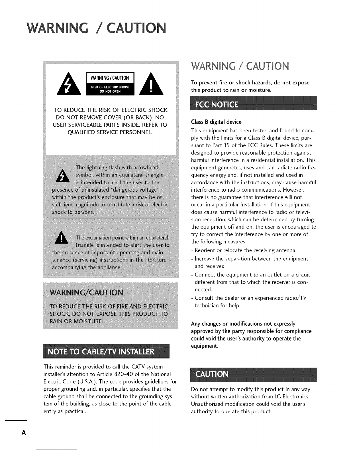
WARNING / CAUTION
To prevent fire or shock hazards, do not expose
this product to rain or moisture.
Class B digital device
This equipment has been tested and found to com-
ply with the limits for a Class B digital device, pur-
suant to Part 15 of the FCC Rules. These limits are
designed to provide reasonable protection against
harmful interference in a residential installation. This
equipment generates, uses and can radiate radio fre-
quency energy and, if not installed and used in
accordance with the instructions, may cause harmful
interference to radio communications. However,
there is no guarantee that interference will not
occur in a particular installation. If this equipment
does cause harmful interference to radio or televi-
sion reception, which can be determined by turning
the equipment off and on, the user is encouraged to
try to correct the interference by one or more of
the following measures:
- Reorient or relocate the receiving antenna.
- Increase the separation between the equipment
and receiver.
- Connect the equipment to an outlet on a circuit
different from that to which the receiver is con-
nected.
- Consult the dealer or an experienced radio/TV
technician for help.
Any changesor modifications not expressly
approved by the party responsible for compliance
could void the user's authority to operate the
equipment.
This reminder is provided to call the CATV system
installer's attention to Article 820-40 of the National
Electric Code (U.S.A.). The code provides guidelines for
proper grounding and, in particular, specifies that the
cable ground shall be connected to the grounding sys-
tem of the building, as close to the point of the cable
entry as practical.
Do not attempt to modify this product in any way
without written authorization from LG Electronics.
Unauthorized modification could void the user's
authority to operate this product
A
SAFETYIN
IMPORTANT SAFETYINSTRUCTIONS
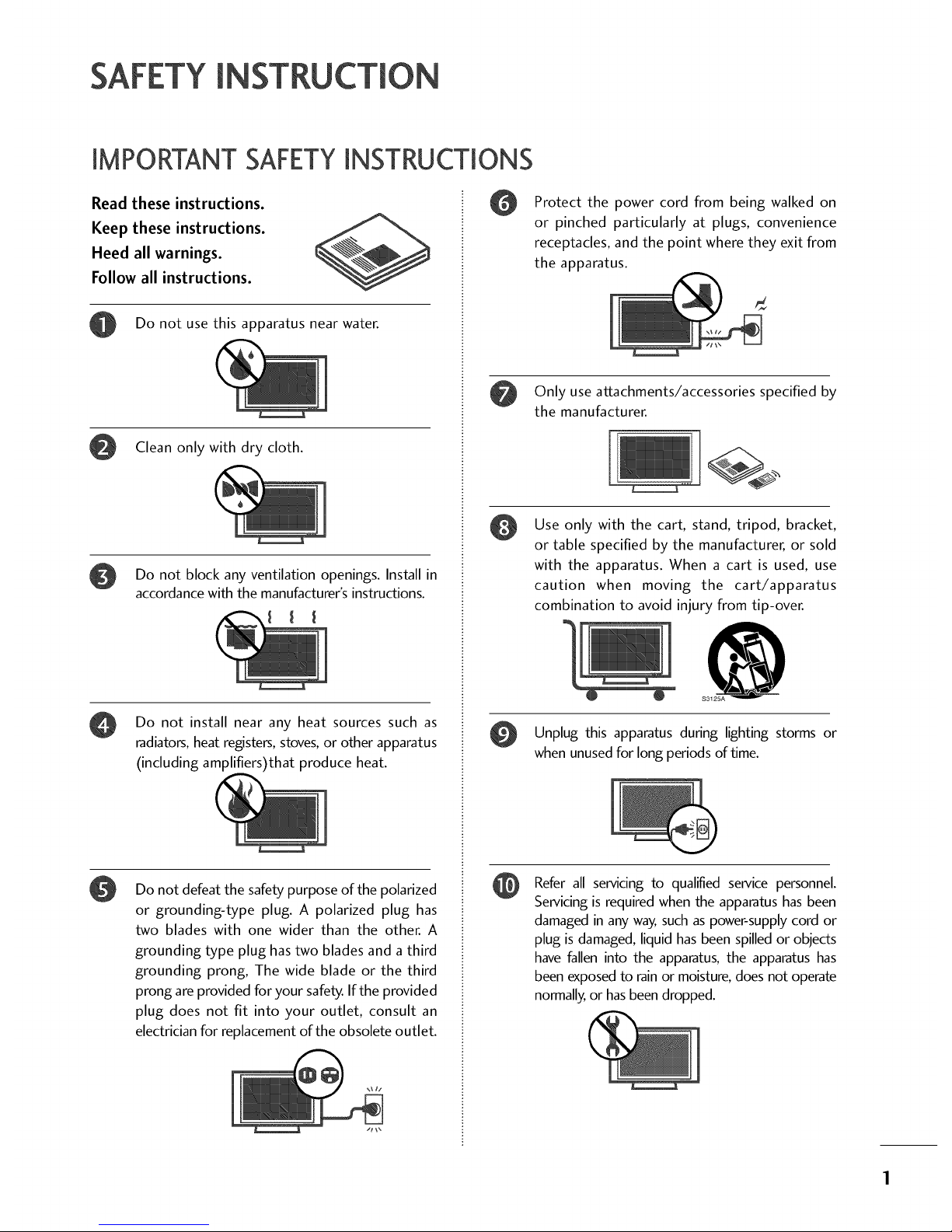
Read these instructions.
Keep these instructions.
Heed all warnings.
Follow all instructions.
Do not use this apparatus near water.
Clean only with dry cloth.
Do not block any ventilation openings. Install in
accordance with the manufacturer's instructions.
Do not install near any heat sources such as
radiators, heat registers, stoves, or other apparatus
(including amplifiers)that produce heat.
0
Do not defeat the safety purpose of the polarized
or grounding-type plug. A polarized plug has
two blades with one wider than the other. A
grounding type plug has two blades and a third
grounding prong, The wide blade or the third
prong are provided for your safety. If the provided
plug does not fit into your outlet, consult an
electrician for replacement of the obsolete outlet.
Protect the power cord from being walked on
or pinched particularly at plugs, convenience
receptacles, and the point where they exit from
the apparatus.
Only use attachments/accessories specified by
the manufacturer.
Use only with the cart, stand, tripod, bracket,
or table specified by the manufacturer, or sold
with the apparatus. When a cart is used, use
caution when moving the cart/apparatus
combination to avoid injury from tip-over.
@
S3125A
Unplug this during lighting storms or
apparatus
when unused for long periods of time.
Refer all servicing to qualified service personnel.
Servicing is required when the apparatus has been
damaged in any way, such as power-supply cord or
plug is damaged, liquid has been spilled or objects
have fallen into the apparatus, the apparatus has
been exposed to rain or moisture, does not operate
normally, or has been dropped.
SAFETYIN
Never touch this apparatus or antenna during a
thunder or lighting storm.
When TV the wall, make not to
mounting
a on sure
install the TV by the hanging power and signal
cables on the back of the TV.
@
Do not allow an impact shock or any objects to fall
into the product, and do not drop onto the screen
with something.
CAUTION concerning the Power Cord :
It is recommend that appliances be placed upon a
dedicated circuit; that is,asingle outlet circuit which
powers only that appliance and has no additional
outlets or branch circuits. Check the specification
page of this owner's manual to be certain.
Do not connect too many appliances to the same
AC power outlet as this could result in fire or elec-
tric shock.
Do not overload wall outlets. Overloaded wall out-
lets, loose or damaged wall outlets, extension cords,
frayed power cords, or damaged or cracked wire
insulation are dangerous. Any of these conditions
could result in electric shock or fire. Periodically
examine the cord of your appliance, and if its
appearance indicates damage or deterioration,
unplug iL discontinue use of the appliance, and
have the cord replaced with an exact replacement
part by an authorized servicer. Protect the power
cord from physical or mechanical abuse, such as
being twisted, kinked, pinched, closed in a door, or
walked upon. Payparticular attention to plugs, wall
outlets, and the point where the cord exits the
appliance.
Do not make the TV with the power cord plugged
in. Do not use a damaged or loose power cord. Be
sure do grasp the plug when unplugging the power
cord. Do not pull on the power cord to unplug the
TV.
@
WARNING - To reduce the risk of fire or electrical
shock, do not expose this product to rain, moisture
or other liquids. Do not touch the TV with wet
hands. Do not install this product near flammable
objects such as gasoline or candles or expose the
TV to direct air conditioning.
Do not expose to dripping or splashing and do not
place objects filled with liquids, such asvases, cups,
etc. on or over the apparatus (e.g. on shelves above
the unit).
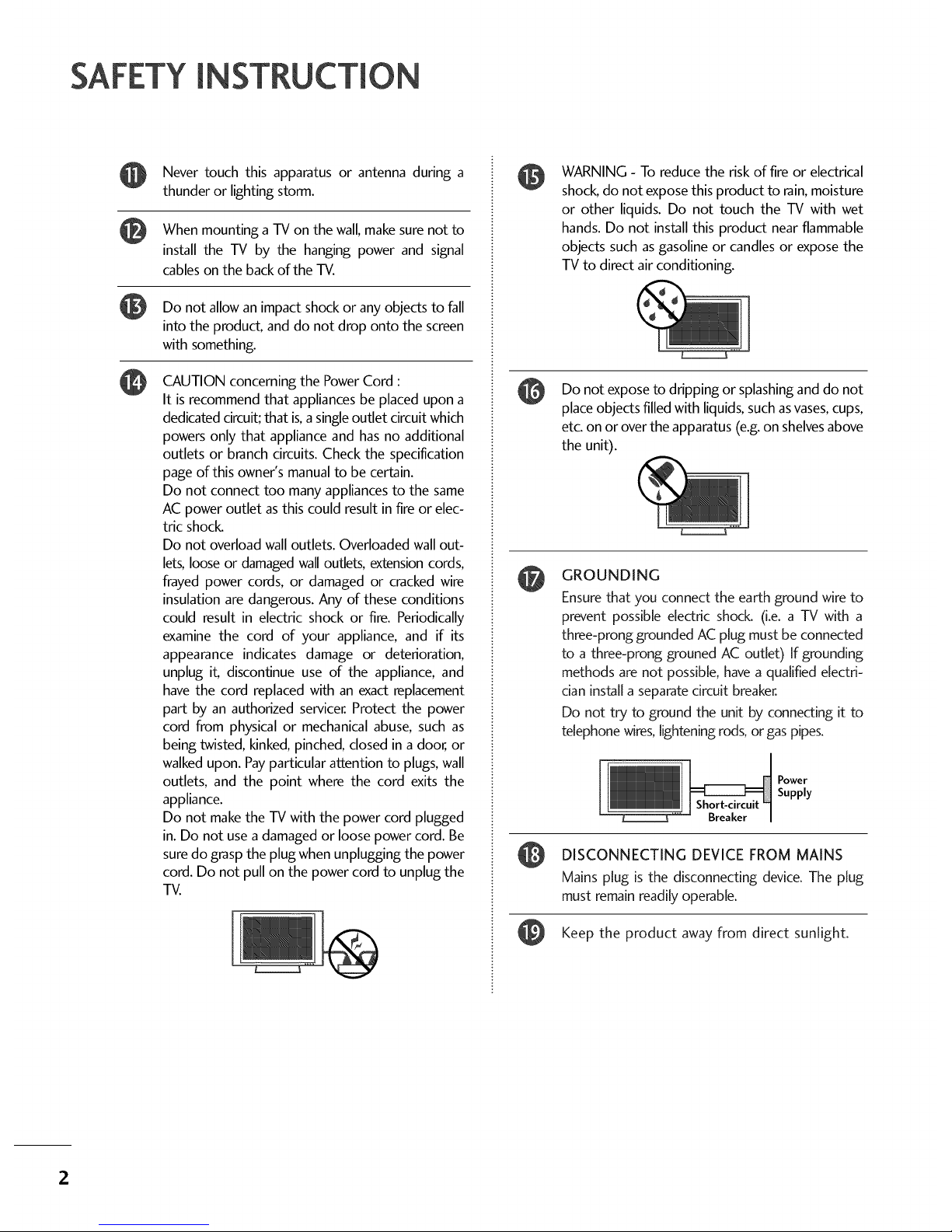
GROUNDING
Ensure that you connect the earth ground wire to
prevent possible electric shock. (i.e. a TV with a
three-prong grounded AC plug must be connected
to a three-prong grouned AC outlet) If grounding
methods are not possible, have a qualified electri-
cian install a separate circuit breaker.
Do not try to ground the unit by connecting it to
telephone wires, lightening rods, or gas pipes.
Power
Supply
Breaker
DISCONNECTING DEVICE FROM MAINS
Mains plug is the disconnecting device. The plug
must remain readily operable.
Keep the product away from direct sunlight.
2
@
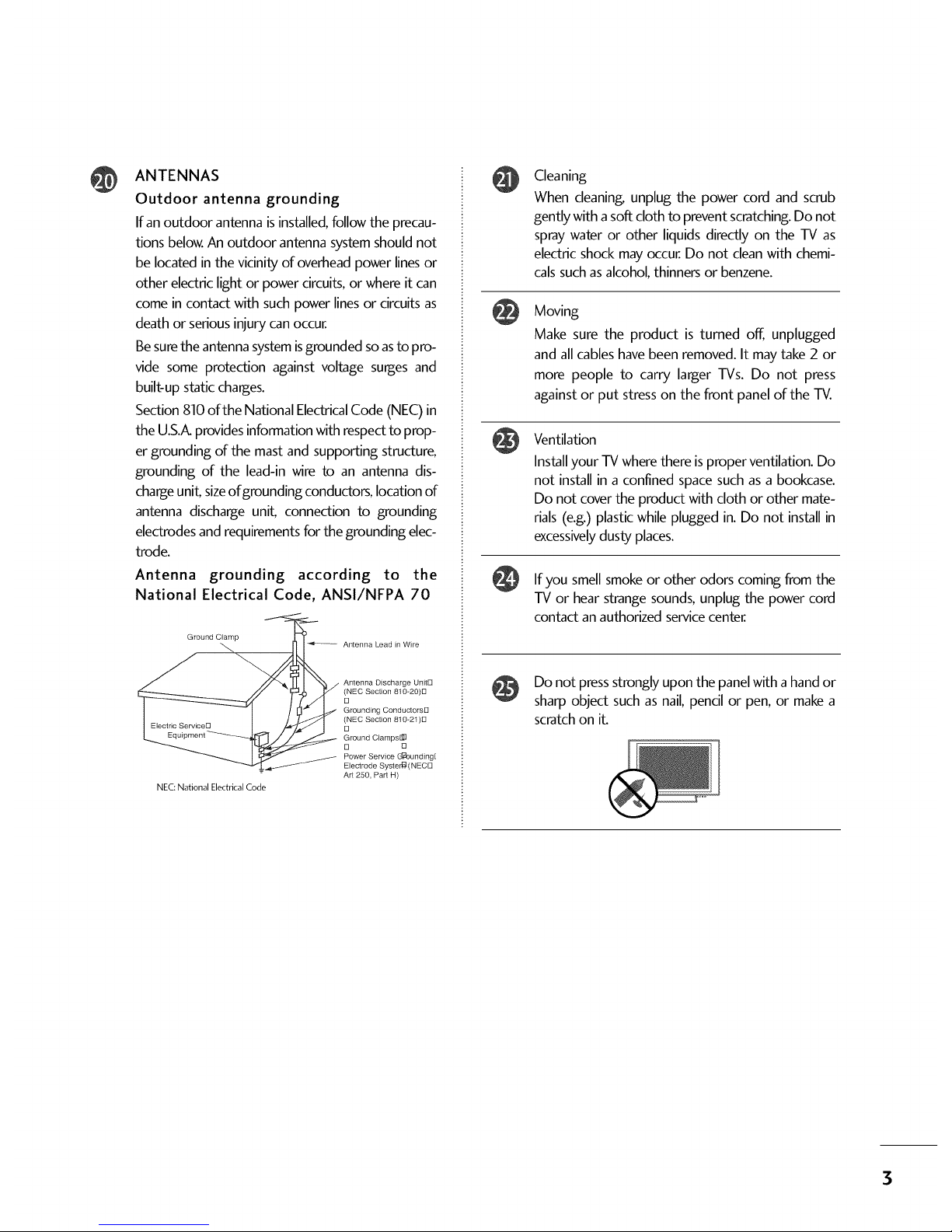
ANTENNAS
Outdoor antenna grounding
If an outdoor antenna is installed, follow the precau-
tions below. An outdoor antenna system should not
be located in the vicinity of overhead power lines or
other electric light or power circuits, or where it can
come in contact with such power lines or circuits as
death or serious injury can occur.
Be sure the antenna system isgrounded soas to pro-
vide some protection against voltage surges and
built-up static charges.
Section 810 of the National Electrical Code (NEC) in
the U.S.A.provides information with respect to prop-
er grounding of the mast and supporting structure,
grounding of the lead-in wire to an antenna dis-
charge uniL sizeof grounding conductors, location of
antenna discharge uniL connection to grounding
electrodes and requirements for the grounding elec-
trode.
Antenna grounding according to the
National Electrical Code, ANSl/NFPA 70
Ground Clamp
_ Antenna Lead in Wire
_ Antenna Discharge UnitE]
E]NEC Section 810-20)8
Grounding Conductorsl3
E]NEC Section 810-21)E]
Ground Clamps@
D 13
Power Service (J:_ounding[
_ Electrode Syster_ (NECl3
Art 250, Part H)
NEC:National Electrical Code
@
@
@
Cleaning
When cleaning, unplug the power cord and scrub
gently with a soft cloth to prevent scratching. Do not
spray water or other liquids directly on the TV as
electric shock may occur. Do not clean with chemi-
cals such as alcohol, thinners or benzene.
Moving
Make sure the product is turned off, unplugged
and all cables have been removed. It may take 2 or
more people to carry larger TVs. Do not press
against or put stress on the front panel of the TV.
Ventilation
Install your TV where there is proper ventilation. Do
not install in a confined space such as a bookcase.
Do not cover the product with cloth or other mate-
rials (e.g.) plastic while plugged in. Do not install in
excessivelydusty places.
If you smell smoke or other odors coming from the
TV or hear strange sounds, unplug the power cord
contact an authorized servicecenter.
Do not press strongly upon the panel with a hand or
sharp object such as nail, pencil or pen, or make a
scratch on iL
3

4
WARNING / CAUTION ............................ A
SAFETY INSTRUCTION ............................ 1
FEATURE OF THIS TV .............................. 5
Accessories ...................................................... 5
Front Panel Controls ......................................... 7
Back Panel Information .................................... 10
Back Cover for Wire Arrangement ..................... 12
Stand Installation ............................................ 15
Attaching the TV to a Wall ............................... 17
Swivel Stand .................................................... 17
Attaching the TV to a Desk .............................. 18
VESAWall Mounting ........................................ 19
Desktop Pedestal Installation ........................... 19
Antenna or Cable Connection .......................... 20
HD ReceiverSetup ......................................... 21
DVD Setup ..................................................... 24
VCR Setup ..................................................... 26
Other A/V Source Setup ................................ 28
Digital Audio Output ...................................... 28
PC Setup ........................................................ 29
Remote Control Functions ............................... 32
Turning On TV ................................................ 34
Channel Selection ........................................... 34
Volume Adjustment ......................................... 34
On-Screen Menus Selection ............................. 35
Channel Setup ................................................ 36
- Auto Scan (EZ Scan)................................. 36
- Add / Delete Channel (Manual Scan)......... 37
- Channel Editing ........................................ 38
DTV Signal Strength ........................................ 39
Channel Label ................................................. 40
Watching DW (Double Window) ....................... 41
Picture Size (Aspect Ratio) Control .................. 43
Preset Picture Settings
- EZ Picture - Preset .................................... 45
- Color Tone - Preset................................... 46
Manual Picture Adjustment
- EZ Picture - User Mode ............................ 47
- Color Tone - User Mode ........................... 48
XD - Picture Improvement Technology ............. 49
Advanced - Cinema Mode ............................... 50
Advanced - Black (Darkness) Level ................... 51
Picture Reset ................................................. 52
Low-PowerPicture Mode ................................ 52
ImageStickingMinimization(ISM)Method ............. 53
Auto Volume Leveler (EZ SoundRite) ................ 54
Preset Sound Setting (EZ Sound) ..................... 55
Sound Setting Adjustment - User Mode ........... 56
BalanceAdjustment ......................................... 57
TV SpeakersOn/Off Setup .............................. 58
Stereo/SAP Broadcasts Setup .......................... 59
Audio Language .............................................. 60
On-Screen Menus Language Selection .............. 61
Caption/Text .................................................. 62
- Analog Broadcasting System Captions ....... 62
- Digital Broadcasting System Captions ........ 63
Caption Options ............................................ 64
Clock Setting .................................................. 65
- Auto Clock Setup .................................... 65
- Manual Clock Setup ................................. 66
Auto On/Off Timer Setting ............................. 67
Auto Shut-off Setting ....................................... 68
Sleep Timer Setting ......................................... 69
Auto Configure (RGB(PC) Mode only) ............. 70
Manual Configure ............................................ 71
Selecting XGA Mode ....................................... 72
Initializing (Reset to Original Factory Settings) .73
Set Password& Lock System ............................ 74
- Setting up Your Password ......................... 74
- Set Password ........................................... 75
- Lock System ............................................. 75
Channel Blocking ............................................ 76
External Input Blocking .................................... 76
Movie & TV Rating.......................................... 77
- Movie Rating (MPAA) ................................ 77
- Downloadable Rating ................................ 77
- TV Rating Children & General ................... 78
- TV Rating English & French ....................... 79
Troubleshooting .............................................. 80
Maintenance ................................................... 82
Product Specifications ..................................... 83
Programming the Remote Control .................... 84
Set ID ............................................................ 86
IRCodes ........................................................ 87
OF THiS TV
FOR LCD TV
If the TV feels cold to the touch, there may be a
small "flicker" when it is turned on. This is normal,
there is nothing wrong with TV.
Some minute dot defects may be visible on the
screen, appearing as tiny red, green, or blue spots.
However, they have no adverse effect on the moni-
tor's performance.
Avoid touching the LCD screen or holding your fin-
ger(s) against it for long periods of time. Doing so
may produce some temporary distortion effects on
the screen.
On Disposal
a. The fluorescent lamp used in this product con-
tains a small amount of mercury.
b. Do not dispose of this product with general
household waste.
c. Disposal of this product must be carried out in
accordance to the regulations of your local
authority.
©
z
PR
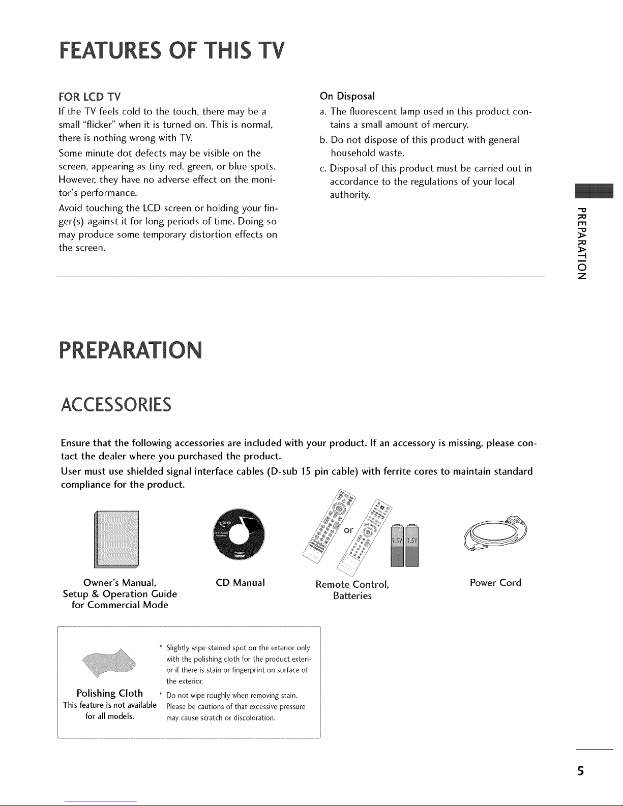
ACCESSORIES
Ensure that the following accessories are included with your product. If an accessory is missing, please con-
tact the dealer where you purchased the product.
User must use shielded signal interface cables (D-sub 15 pin cable) with ferrite cores to maintain standard
compliance for the product.
Owner's Manual,
Setup & Operation Guide
for Commercial Mode
CD Manual Remote Control, Power Cord
Batteries
Polishing Cloth
Thisfeatureisnot available
for all models.
* Slightly wipe stained spot on the exterior only
with the polishing cloth for the product exteri-
or if there is stain or fingerprint on surface of
the exterior,
* Do not wipe roughly when removing stain.
Please be cautions of that excessive pressure
may cause scratch or discoloration.
5
;D
m
0
z
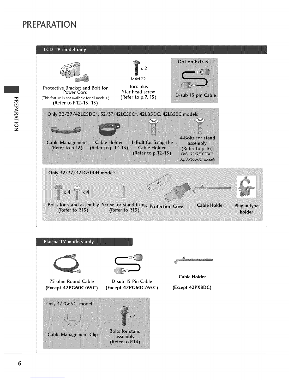
Protective Bracket and Bolt for
Power Cord
(This feature is not available for all models.)
(Refer to R12-13, 15)
x2
M4xL22
Torx plus
Star head screw
(Refer to p.Z 15)
75 ohm Round Cable
(Except 42PG60C/65C)
D-sub 15 Pin Cable
(Except 42PG60C/65C)
Cable Holder
(Except 42PX8DC)
6
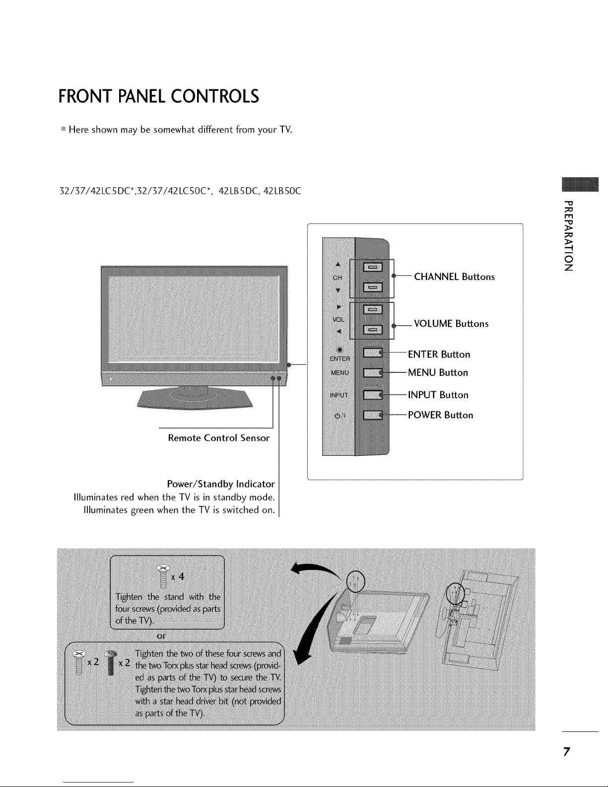
FRONT PANELCONTROLS
Here shown may be somewhat different from your TV.
32/37/42LC5DC*,32137142LC50C*, 42LB5DC, 42LB50C
Remote Control Sensor
Power/Standby Indicator
Illuminates red when the TV is in standby mode.
Illuminates green when the TV is switched on.
Buttons
Buttons
Button
Button
Button
Button
-O
_o
r_
_o
©
z
7

PREPARATION
32LX5DC*, 32LX50C*
O
z
Remote Control Sensor
Power/Standby
Indicator
Illuminates red when the
TV is in standby mode.
Illuminates green when
the TV is switched on.
ON/OFF Button
INPUT Button
MENU Button
ENTER Button
VOLUME Buttons
CHANNEL Buttons
32/37/42LGSOOH
Intelligent Sensor
Adjusts picture according to
the surrounding conditions
Indicator
Illuminates red in standby mode.
Illuminates blue when the set is switched on.
Remote Control Sensor
POWER Button
CHANNEL
Buttons
VOLUME
Buttons
-- ENTER Button
Button
Button
8
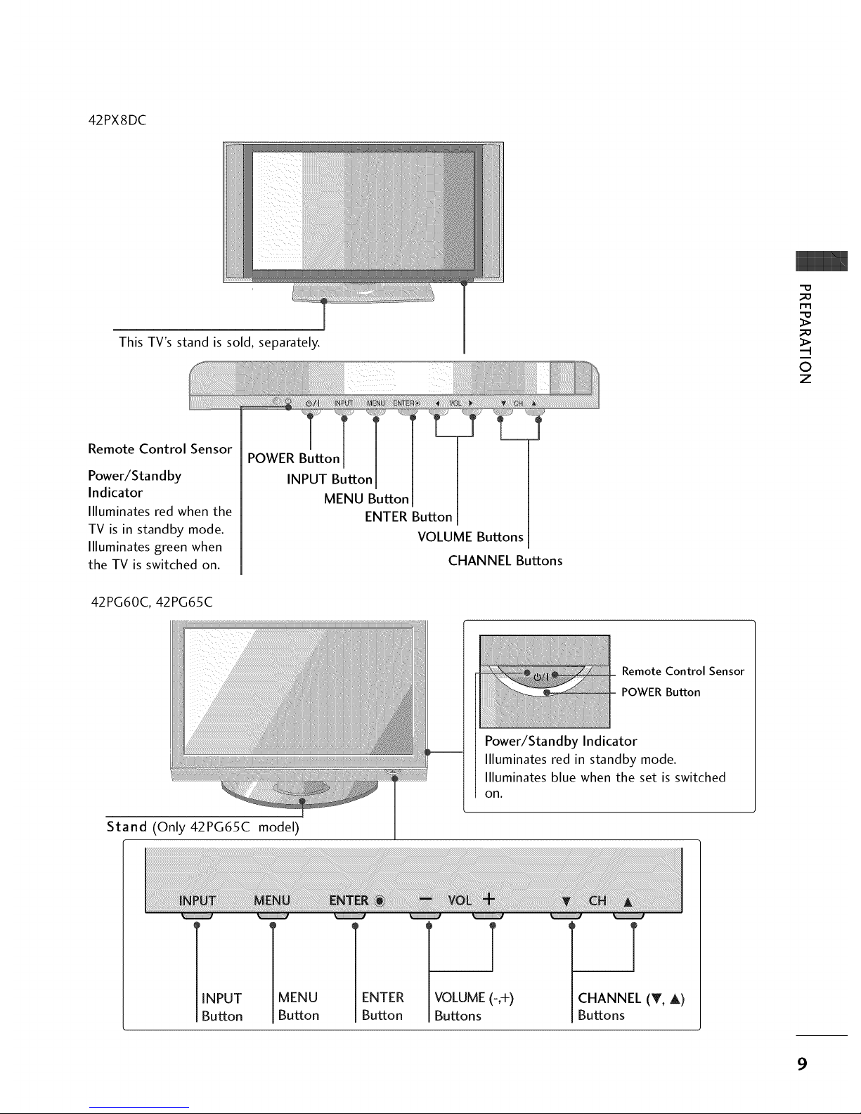
42PX8DC
This TV's stand is sold, separately.
-0
_o
m
_o
©
z
Remote Control Sensor
Power/Sta nd by
Indicator
llluminates red when the
TV is in standby mode.
llluminates green when
the TV is switched on.
POWER Button
INPUT Button
MENU Button
ENTER Button
VOLUME Buttons
CHANNEL Buttons
42PG60C, 42PG65C
MENU ENTER
Button Button
Remote Control Sensor
POWER Button
Stand (Only42PG65C model)
Power/Standby Indicator
llluminates red in standby mode.
Illuminates blue when the set is switched
on.
INPUT
Button
T
VOLUME (-,+)
Buttons
T
CHANNEL (T, A)
Buttons
9
PREPARATION
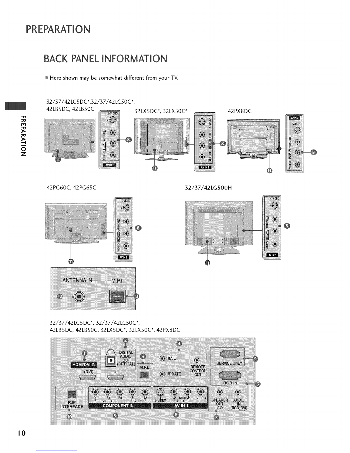
BACK PANELINFORMATION
,,,IHere shown may be somewhat different from your TV.
-O
m
©
z
32/37/42 LC5DC*,32/37/42 LCSOC*,
42LBSDC, 42LB50C
iii ii_ _
32LXSDC*, 32LX50C*
42PX8DC
S-_IDEO
42PG60C, 42PG65C
i _iii
_iiiiiiiiiiiiiiiiiiiii_
32/37/42LG500H
_ VIDE0
52/57/42LC5 DC*, 52/57/42LC50C*,
42LBSDC, 42LB50C, 32LXSDC*, 32LX50C*, 42PX8DC
10
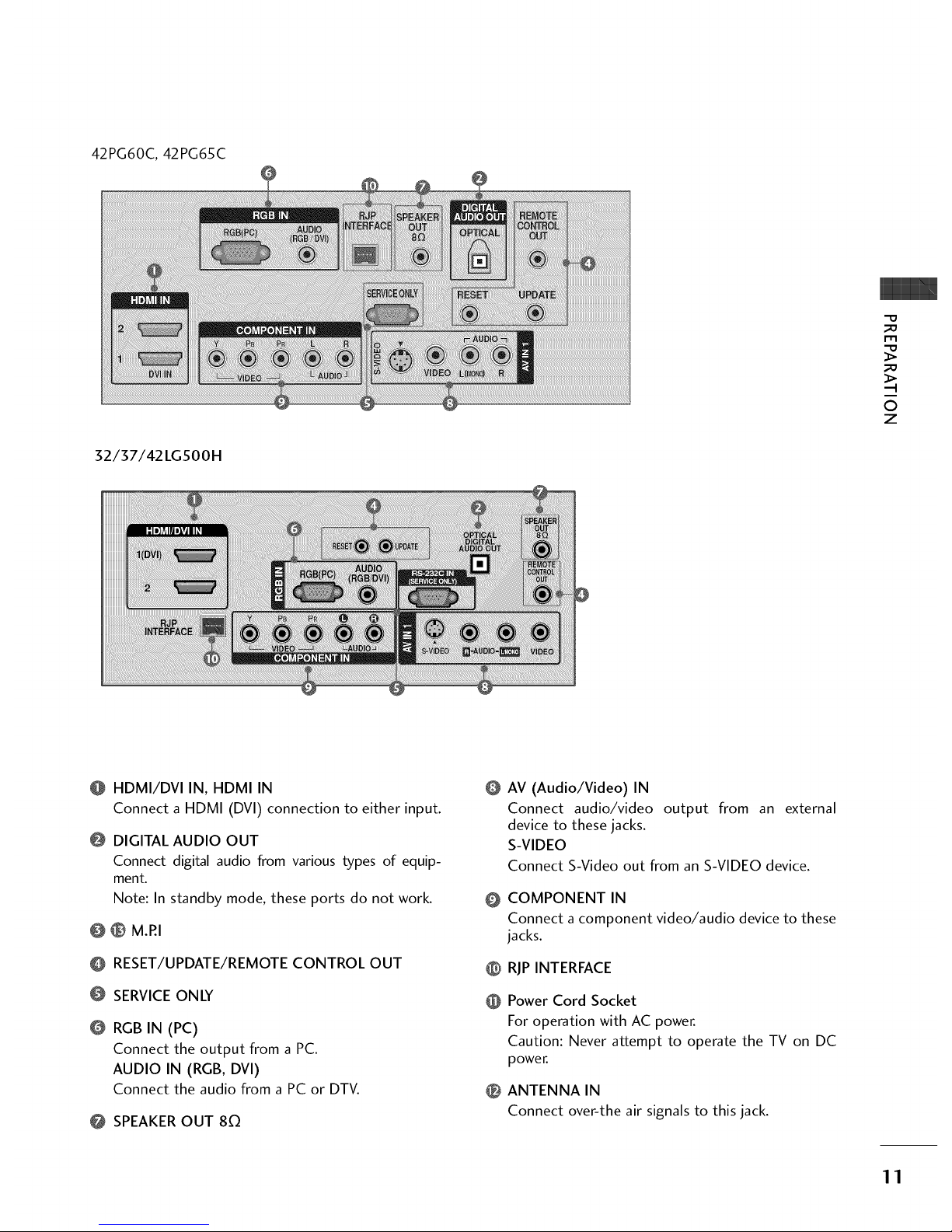
42PG60C, 42PG65C
O
32/37/42 LG500H
"O
r'rl
....-t
©
Z
HDMI/DVI IN, HDMI IN
Connect a HDMI (DVI) connection to either input.
@ DIGITAL AUDIO OUT
Connect digital audio from various types of equip-
ment.
Note: In standby mode, these ports do not work.
@ _ M.RI
O RESET/UPDATE/REMOTE CONTROL OUT
SERVICEONLY
RGBIN (PC)
Connect the output from a PC.
AUDIO IN (RGB, DVI)
Connect the audio from a PC or DTV.
@ SPEAKEROUT 80
O
AV (Audio/Video) IN
Connect audio/video output from an external
device to these jacks.
S-VIDEO
Connect S-Video out from an S-VIDEO device.
COMPONENT IN
Connect a component video/audio device to these
jacks.
@ RJP INTERFACE
Power Cord Socket
For operation with AC power.
Caution: Never attempt to operate the TV on DC
power.
0 ANTENNA IN
Connect over-the air signals to this jack.
11
PREPARATION
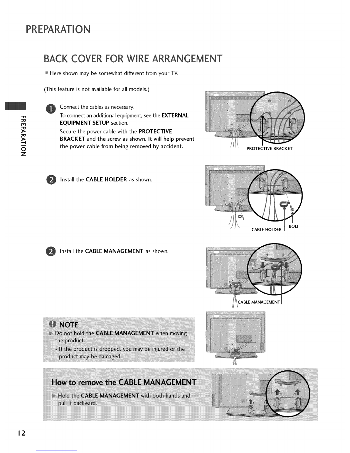
BACKCOVERFORWIREARRANGEMENT
,,,IHere shown may be somewhat different from your TV.
©
Z
(This feature is not available for all models.)
Connect the cables as necessary.
To connect an additional equipment, see the EXTERNAL
EQUIPMENT SETUP section.
Secure the power cable with the PROTECTIVE
BRACKET and the screw as shown. It will help prevent
the power cable from being removed by accident.
PROTECTIVE BRACKET
Install the CABLE HOLDER as shown.
BOLT
CABLE HOLDER
Install the CABLE MANAGEMENT as shown.
12
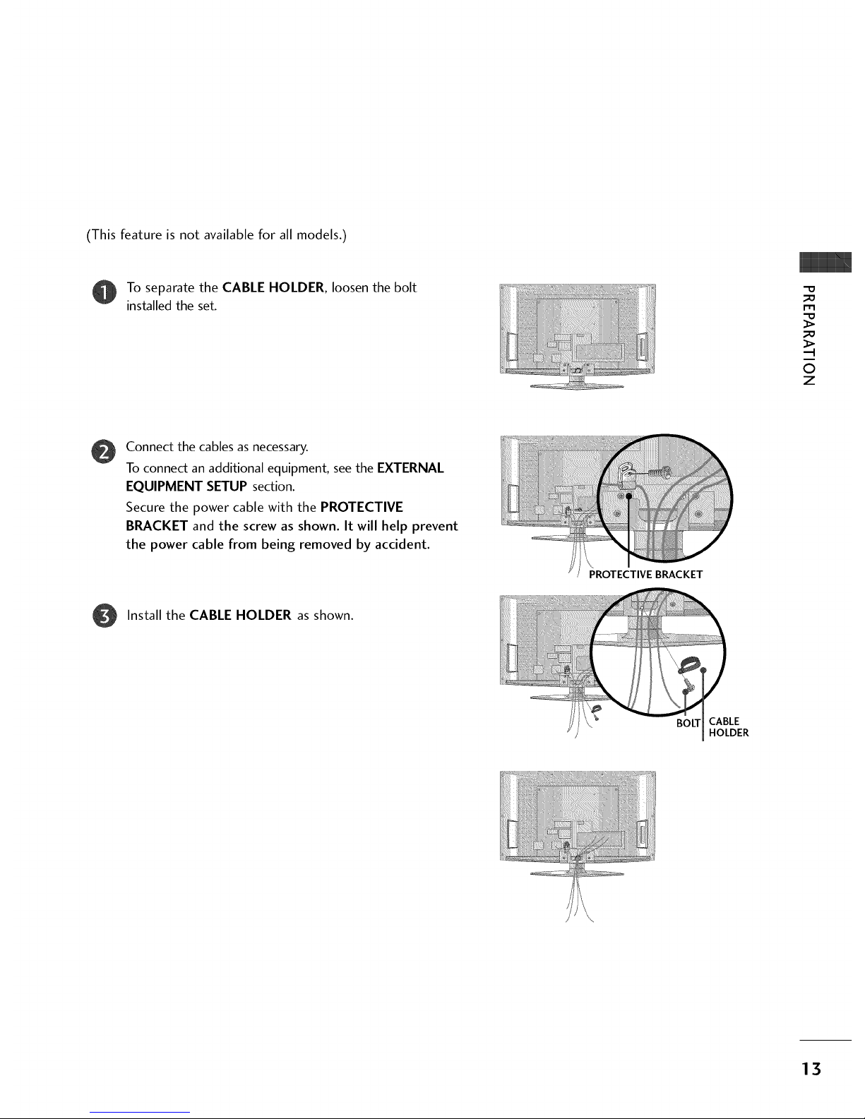
(This feature is not available for all models.)
To separate the CABLE HOLDER, loosen the bolt
installed the set.
_D
m
_D
©
z
@
Connect the cables as necessary.
To connect an additional equipment, see the EXTERNAL
EQUIPMENT SETUP section.
Secure the power cable with the PROTECTIVE
BRACKET and the screw as shown. It will help prevent
the power cable from being removed by accident.
PROTECTIVE BRACKET
Install the CABLE HOLDER as shown.
BOLT CABLE
HOLDER
\
13
PREPARATION
BACKCOVERFORWIREARRANGEMENT
Here shown may be somewhat different from your TV.
©
Z
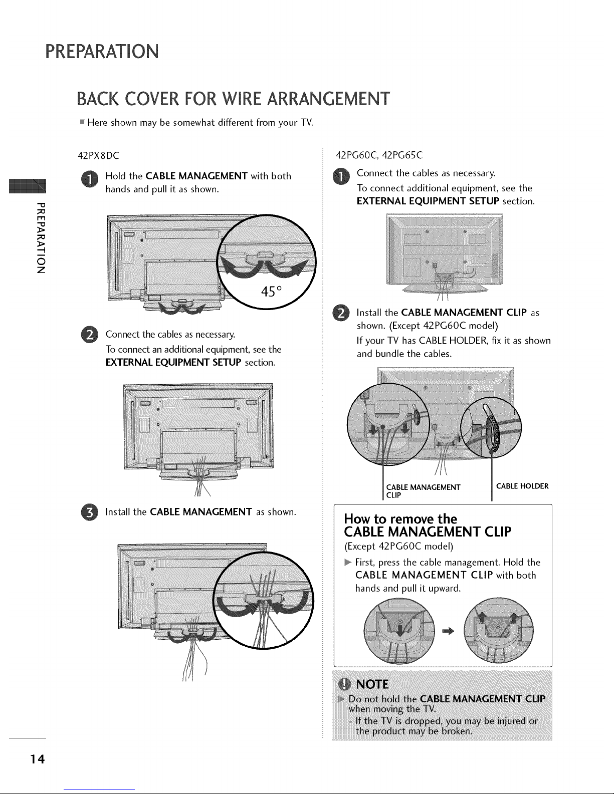
42PX8DC
Hold the CABLE MANAGEMENT with both
hands and pull it as shown.
@
Connect the cables as necessary.
To connect an additional equipment, see the
EXTERNAL EQUIPMENT SETUP section.
O Install the CABLE MANAGEMENT as shown.
42PG60C, 42PG65C
Connect the cables asnecessary.
To connect additional equipment, seethe
EXTERNAL EQUIPMENT SETUP section.
Install the CABLE MANAGEMENT CLIP as
shown. (Except 42PG60C model)
If your TV has CABLE HOLDER, fix it as shown
and bundle the cables.
CABLE MANAGEMENT CABLE HOLDER
CLIP
How to remove the
CABLE MANAGEMENT CLIP
(Except 42PG60C model)
First, press the cable management. Hold the
CABLE MANAGEMENT CLIP with both
hands and pull it upward.
14
32/3 7/42LGSooH
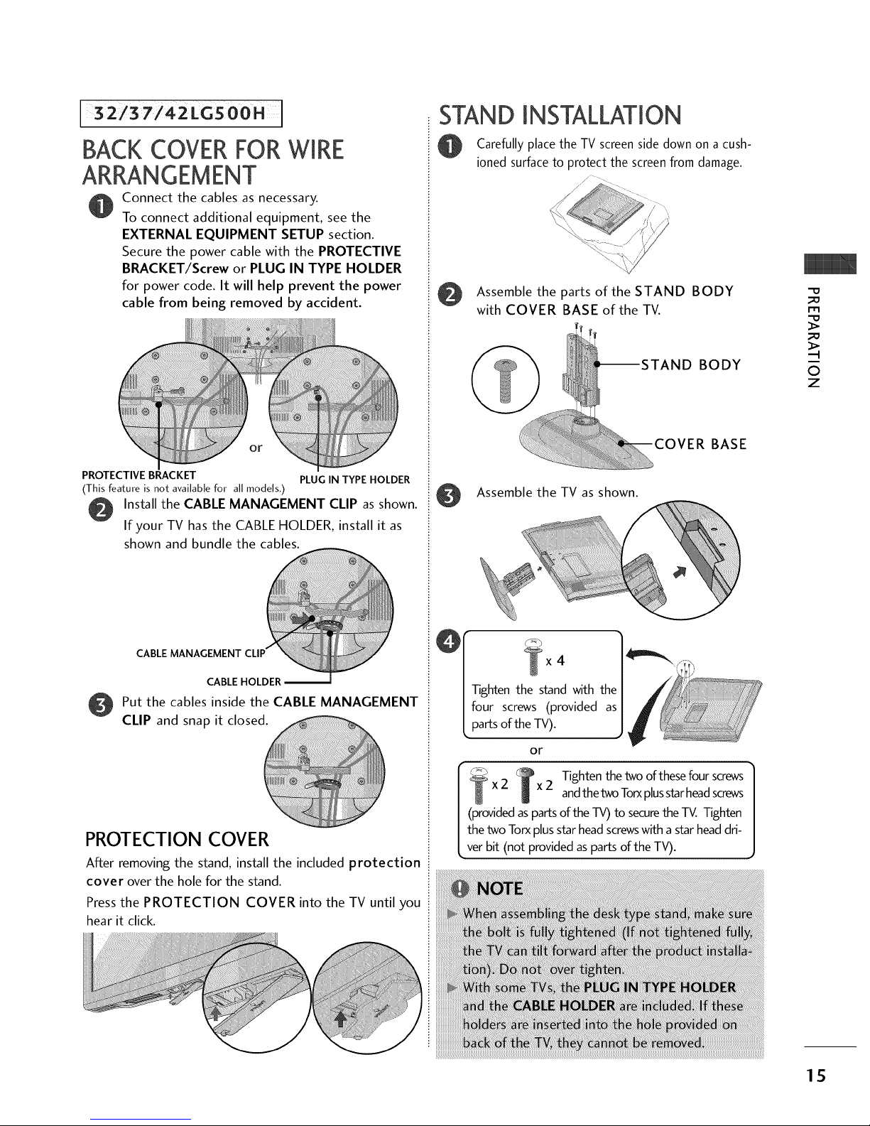
BACKCOVERFORWIRE
ARRANGEMENT
Connect the cables as necessary.
To connect additional equipment, see the
EXTERNAL EQUIPMENT SETUP section.
Secure the power cable with the PROTECTIVE
BRACKET/Screw or PLUG IN TYPE HOLDER
for power code. It will help prevent the power
cable from being removed by accident.
........................® o
PROTECTIVE BRACKET PLUG IN TYPE HOLDER
(This feature is not available for all models.)
Install the CABLE MANAGEMENT CLIP as shown.
If your TV has the CABLE HOLDER, install it as
shown and bundle the cables.
CABLE MANAGEMENT
CABLE HOLDER
O Put the cables inside the CABLE MANAGEMENT
CLIP and snap it closed._
PROTECTION COVER
After removing the stand, install the included protection
cover over the hole for the stand.
Press the PROTECTION COVER into the TV until you
hear it click.
STAND INSTALLATION
Carefully place the TV screen side down on a cush-
ioned surface to protect the screen from damage.
//
Assemble the parts of the STAND BODY
with COVER BASE of the TV.
BODY
BASE
Assemble the TV as shown.
4
or
f _ _ Tighten the two of these four screws
/-_ xZ x2 andthetwoTorxplusstarheadscrews
J
| (provided as parts of the TV) to securethe TV. Tighten
| the two Torxplus starhead screwswith astar headdri-
L,ver bit (not provided as parts of the TV).
-0
_o
m
_o
0
z
15
PREPARATION
STAND INSTALLATION
m
©
z
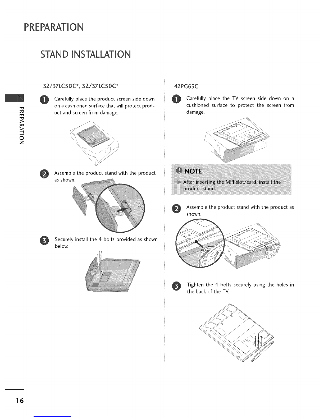
32/37LCSDC*, g2ig7LCS0C*
Carefully place the product screen side down
on a cushioned surface that will protect prod-
uct and screen from damage.
Assemble the product stand with the product
as shown.
Securely install the 4 bolts provided as shown
below.
42PG65C
Carefully place the TV screen side down on a
cushioned surface to protect the screen from
damage.
Assemble the product stand with the product as
shown.
Tighten the 4 bolts securely using the holes in
the back of the TV.
16

ATTACHINGTHETV TO A WALL
This feature is not available for all models.
We recommend that you set up the TV close to a wall so it cannot fall over if pushed backwards.
Additionally, we recommend that the TV be attached to a wall so it cannot be pulled in a forward direction,
potentially causing injury or damaging the product.
Caution: Please make sure that children don't climb on or hang from the TV.
Insert the TV brackets (or eye-bolts) and bolts to tighten the product to the wall as shown in the picture.
If your product has the bolts in the eye-bolts position before inserting the eye-bolts, loosen the bolts.
Secure the wall brackets with the bolts (not provided as parts of the product, must purchase separately) on
the wall. Match the height of the bracket that is mounted on the wall to the holes in the product.
Ensure the eye-bolts or brackets are tightened securely.
©
Z
0,_Use a sturdy rope (not provided as parts of the product, must pur-
chase separately) to tie the product. It is safer to tie the rope so it
becomes horizontal between the wall and the product.
SWIVELSTAND
20 °
90 °
(37LC5DC1,42LC5DC, 42LC50C, 42PX8DC,
42LB5DC, 42LB50C, 42PG65C models)
(32LX5DC/S, 32LX50C/S, 32LC5DC/S,
32LC50C/S, 37LC5DC, 37LC50C,32/37/42LG500H
models)
The TV can be conveniently swivelled on its stand 20°or 90 ° to the left or right to provide the opti-
mum viewing angle.
17
PREPARATION
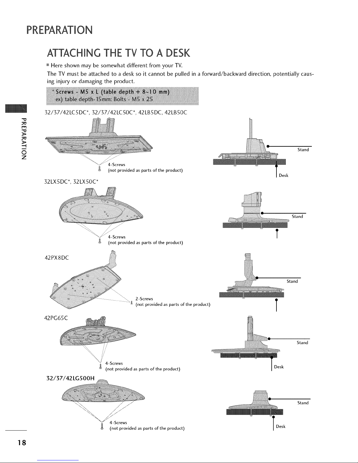
ATTACHING THE TV TO A DESK
,,,IHere shown may be somewhat different from your TV.
The TV must be attached to a desk so it cannot be pulled in a forward/backward direction, potentially caus-
ing injury or damaging the product.
-o
_o
m
_o
©
z
32/37/42LC5DC*, 32/37/42LC50C*, 42LB5DC, 42LB50C
4-Screws
(not provided as parts of the product)
32LX5DC*, 32LX50C*
Stand
D
Stand
4-Screws
g (not provided as parts of the product)
4 g 2-Screws
(not provided as parts of the product)
42PG65C
T
Stand
T
32/37/42 LGSOOH
//'
//
//'
i/
4 4-Screws
g (not provided as parts of the product)
Stand
,/ /
\;_\, / /
"_ 4-Screws
(not provided as parts of the product)
T Desk
Stand
18
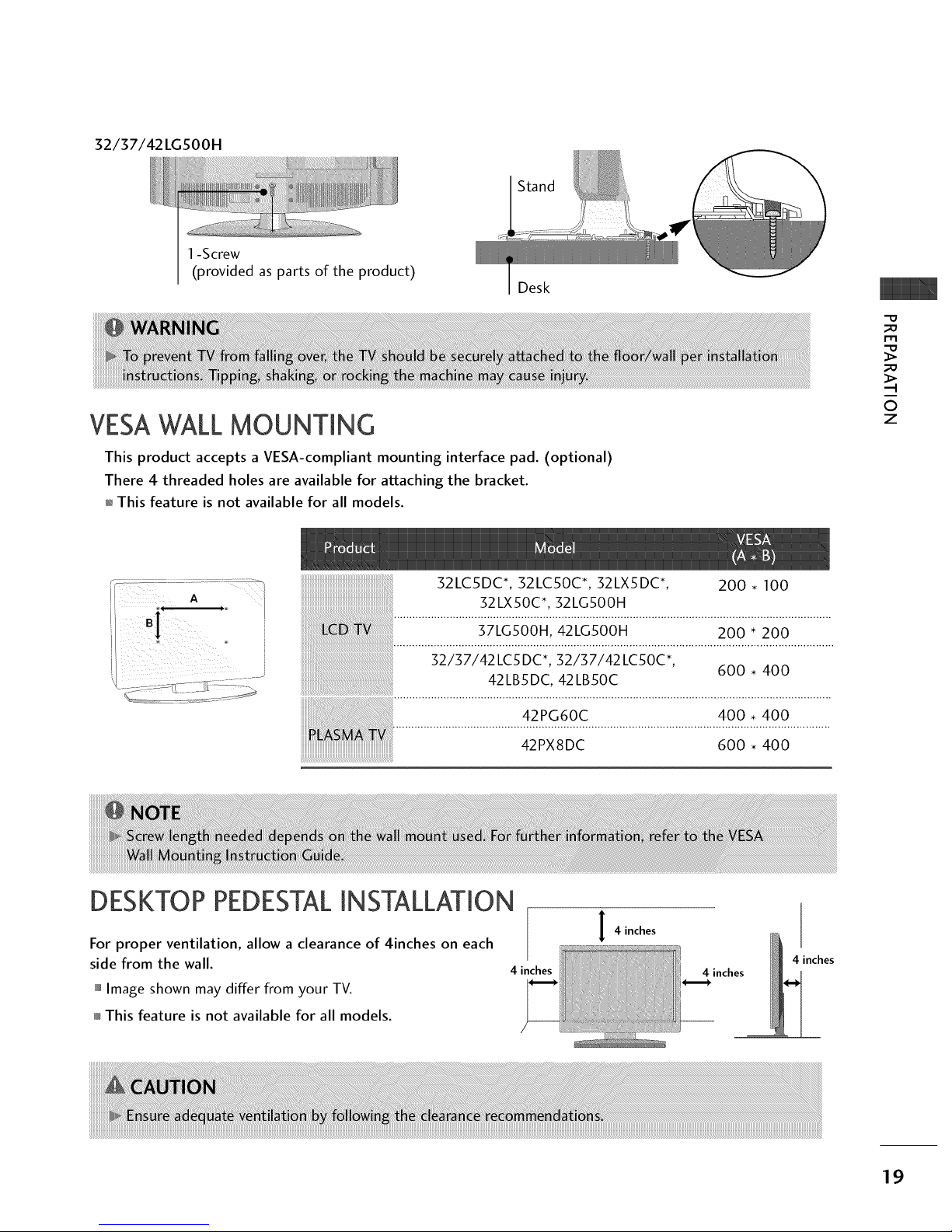
32/37/42LGSOOH
1-Screw
(provided as parts of the product)
Stand
Desk
VESAWALLMOUNTING
This product accepts a VESA-compliant mounting interface pad. (optional)
There 4 threaded holes are available for attaching the bracket.
01_This feature is not available for all models.
_D
m
_D
0
z
52LC5DC*, 52LC50C*, 52LX5DC*,
52LX50C*, 52LG500H
DESKTOP PEDESTALINSTALLATION
200 • 100
42PG60C
42PX8DC
400 • 400
600 • 400
For proper ventilation, allow a clearance of 4inches on each
side from the wall.
,,,iImage shown may differ from your TV.
This feature is not available for all models.
4 inches
I 4 inches
4 inches
4 inches
19

PREPARATION
ANTENNA OR CABLECONNECTION
_D
r'rl
_D
.-t
©
z
1. Antenna (Analog or Digital)
Wall Antenna Socket or Outdoor Antenna without a Cable Box
Connections.
For optimum picture quality, adjust antenna direction if needed.
2. Cable
Cable TV
Wall Jack
Be careful not to bend the bronze wire
when connecting the antenna.
iiiiiiiiiiiiiiiii__!_!!i!ii_iiiiiiiiiiiiiiiiiiiiii'¸''
UHF
Antenna __
VHF
01_To improve the picture quality in a poor signal area, please purchase a signal amplifier and install properly.
01_If the antenna needs to be split for two TV's, install a 2-Way Signal Splitter.
01_If the antenna is not installed properly, contact your dealer for assistance.
2O

EXTERNAL EQUIPMENT SETUP
01_To prevent the equipment damage, never plug in any power cords until you have finished connecting all equipment.
01_This part of external equipment setup mainly use picture for LCD TV(Except 32/37/42LGSOOH) models.
HD RECEIVERSETUP
This TV can receive Digital Over-the-air/Cable signals without an external digital set-top box. However, if you
do receive digital signals from a digital set-top box or other digital external device, refer to the figure as shown
below.
When connecting Component cable
1. How to connect
Connect the video outputs (Y, PB, PR) of the digital set
top box to the COMPONENT IN VIDEO jacks on
the set. Match the jack colors
(Y = green, PB = blue, and PR = red).
Connect the audio output of the digital set-top box to
the COMPONENT IN AUDIO jacks on the set.
2. How to use
Turn on the digital set-top box.
(Refer to the owner's manual for the digital set-top box.)
Select Component input source with using the INPUT
button on the remote control.
m
x
m
z
m
_D
c
m
z
m
c
Yes No
Yes Yes
Yes Yes
Yes Yes
21
EXTERNALEQUIPMENT SETUP
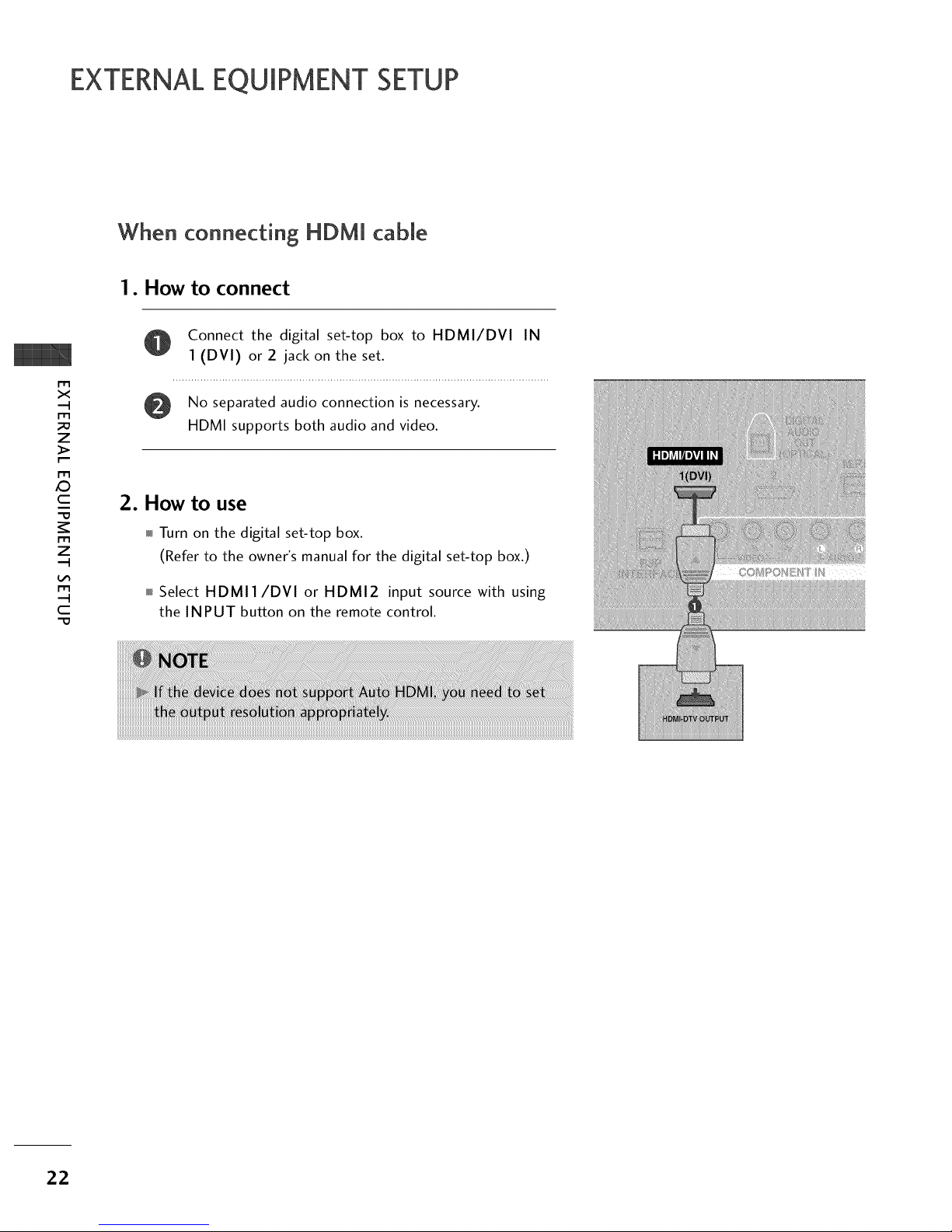
When connecting HDM[ cable
1. How to connect
m
x
m
_o
z
_>
m
_D
c
"O
m
z
m
c
"O
Connect the digital set-top box to HDMI/DVI IN
1 (DVI) or 2 jack on the set.
No separated audio connection is necessary.
HDMI supports both audio and video.
2. How to use
Turn on the digital set-top box.
(Refer to the owner's manual for the digital set-top box.)
Select HDMI1/DVI or HDMI2 input source with using
the INPUT button on the remote control.
22

When connecting HDM[ to DVi cable
@
m
x
m
_o
z
m
XZ)
c
m
z
m
c
1. How to connect
Connect the DVI output of the digital set-top box to the HDMI/DVI IN 1 (DVI) or 2 jack on the set.
Connect the audio of the box to the AUDIO IN (RGB,DVI) the set.
output digital set-top jack
on
2. How to use
01_Turn on the digital set-top box. (Refer to the owner's manual for the digital set-top box.)
01_Select HDMI1/DVI or HDMI2 input source with using the INPUT button on the remote control.
23
EXTERNALEQUIPMENT SETUP
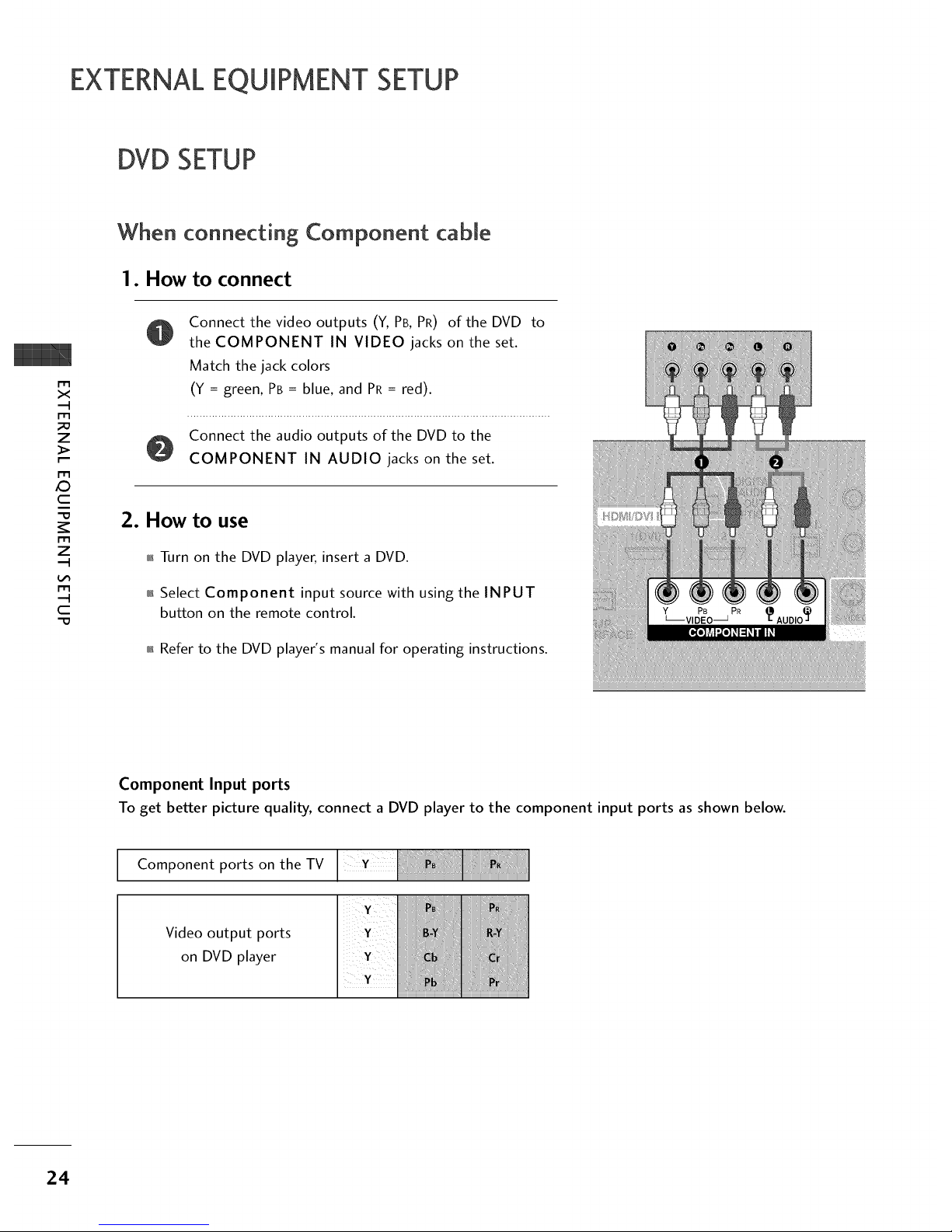
DVD SETUP
m
x
m
z
m
XD
c
m
z
m
c
-0
When connect+ng Component cable
1. How to connect
Connect the video outputs (Y, PB, PR) of the DVD
the COMPONENT IN VIDEO jacks on the set.
Match the jack colors
(Y = green, PB = blue, and PR= red).
to
Connect the audio outputs of the DVD to the
COMPONENT IN AUDIO jacks on the set.
2. How to use
m Turn on the DVD player, insert a DVD.
m Select Component input source with using the INPUT
button on the remote control.
m Refer to the DVD player's manual for operating instructions.
PB PR
Component Input ports
To get better picture quality, connect a DVD player to the component input ports as shown below.
Component ports on the TV
Video output ports
on DVD player
24
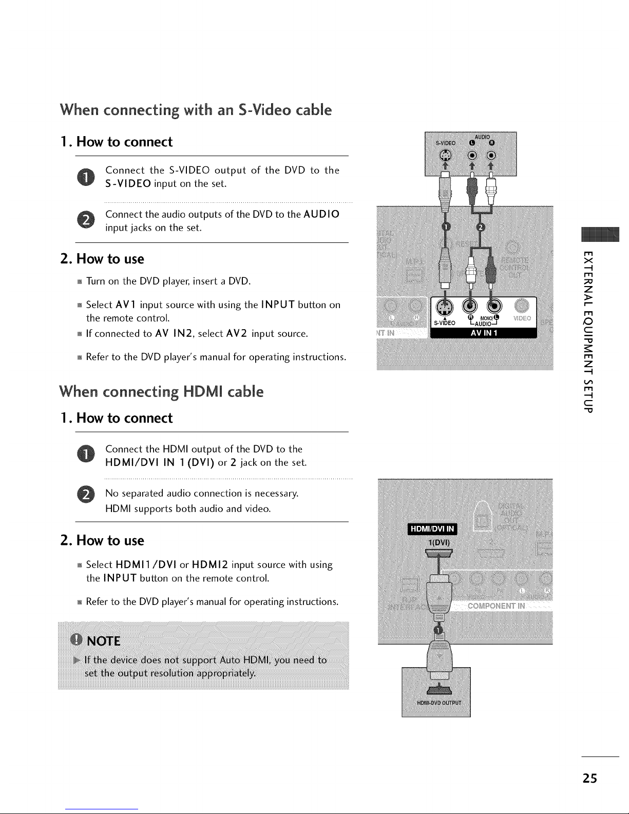
When connecting with an S-Video cable
1. How to connect
Connect the S-VIDEO output of the DVD to the
S-VIDEO input on the set.
Connect the audio outputs of the DVD to the AUDIO
input jacks on the set.
2. How to use
01_Turn on the DVD player, insert a DVD.
01_Select AV1 input source with using the INPUT button on
the remote control.
01_If connected to AV IN2, select AV2 input source.
01_Refer to the DVD player's manual for operating instructions.
When connecting HDMI cable
1. How to connect
m
x
m
z
m
XD
c
m
z
m
c
-0
Connect the HDMI output of the DVD to the
HDMI/DVI IN 1 (DVI) or 2 jack on the set.
No separated audio connection is necessary.
HDMI supports both audio and video.
2. How to use
01_Select HDMI1/DVI or HDMI2 input source with using
the INPUT button on the remote control.
n_Refer to the DVD player's manual for operating instructions.
2S
 Loading...