

LG 32LX4DC, 32LX4DCS User Manual
LCD TV
Please read this manual carefully before operating your set.
Retain it for future reference.
Record model number and serial number of the set.
See the label attached on the back cover and quote
this information to your dealer
when you require service.
OWNER’S MANUAL
MODELS: 32LX4DC
32LX4DCS
32LX4DCW
Internet Home Page : http://www.lgcommercial.com
P/NO : 3828TUL309N (0608-REV01)
Printed in Korea

2
Warning
WARNING:
TO REDUCE THE RISK OF ELECTRIC SHOCK DO NOT REMOVE COVER (OR BACK). NO USER
SERVICEABLE PARTS INSIDE. REFER TO QUALIFIED SERVICE PERSONNEL.
The lightning flash with arrowhead symbol, within an equilateral triangle, is intended to alert the user to
the presence of uninsulated “dangerous voltage” within the product’s enclosure that may be of sufficient magnitude to constitute a risk of electric shock to persons.
The exclamation point within an equilateral triangle is intended to alert the user to the presence of
important operating and maintenance (servicing) instructions in the literature accompanying the appliance.
NOTE TO CABLE/TV INSTALLER:
This reminder is provided to call the CATV system installer’s attention to Article 820-40 of the National Electric
Code (U.S.A.). The code provides guidelines for proper grounding and, in particular, specifies that the cable
ground shall be connected to the grounding system of the building, as close to the point of the cable entry as practical.
REGULATORY INFORMATION
This equipment has been tested and found to comply with the limits for a Class B digital device, pursuant to Part
15 of the FCC Rules. These limits are designed to provide reasonable protection against harmful interference in
a residential installation. This equipment generates, uses and can radiate radio frequency energy and, if not
installed and used in accordance with the instructions, may cause harmful interference to radio communications.
However, there is no guarantee that interference will not occur in a particular installation. If this equipment does
cause harmful interference to radio or television reception, which can be determined by turning the equipment off
and on, the user is encouraged to try to correct the interference by one or more of the following measures:
- Reorient or relocate the receiving antenna.
- Increase the separation between the equipment and receiver.
- Connect the equipment into an outlet on a circuit different from that to which the receiver is connected.
- Consult the dealer or an experienced radio/TV technician for help.
Any changes or modifications not expressly approved by the party responsible for compliance could void the
user’s authority to operate the equipment.
CAUTION:
Do not attempt to modify this product in any way without written authorization from LG Electronics Corporation.
Unauthorized modification could void the user’s authority to operate this product.
U.S.A. only -----------------------------------------------
COMPLIANCE:
The responsible party for this product’s compliance is:
LG Electronics U.S.A., Inc.
1000 Sylvan Avenue, Englewood Cliffs, NJ 07632
Phone: (888) 865-3026
http://www.lgcommercial.com
---------------------------------------------------------------
CAUTION
RISK OF ELECTRIC SHOCK
DO NOT OPEN
W
W
arning
arning
3
Safety Instructions
WARNING :
To Reduce The Risk Of Fire Or Electric Shock, Do Not Expose This Apparatus To Rain Or Moisture.
Apparatus shall not be exposed to dripping or splashing and no objects filled with liquids, such as vases, shall be placed on the
apparatus.
IMPORTANT SAFETY INSTRUCTIONS
1. Read these instructions.
2. Keep these instructions.
3. Heed all warnings.
4. Follow all instructions.
5. Do not use this apparatus near water.
6. Clean only with a dry cloth.
7. Do not block any of the ventilation openings. Install in
accordance with the manufacturer’s instructions.
8. Do not install near any heat sources such as radiators,
heat registers, stoves, or other apparatus (including
amplifiers) that produce heat.
9. Do not defeat the safety purpose of the polarized or
grounding type plug. A polarized plug has two blades
with one wider than the other. A grounding type plug has
two blades and a third grounding prong. The wide blade
or the third prong is provided for your safety. When the
provided plug does not fit into your outlet, consult an
electrician for replacement of the obsolete outlet.
10. Protect the power cord from being walked on or
pinched particularly at plugs, convenience receptacles, and the point where they exit from the apparatus.
11. Only use the attachments / accessories specified by
the manufacturer.
Safety Instructions
Safety Instructions
O
w
n
e
r's
M
a
n
u
a
l
4
Safety Instructions
Safety Instructions continued
Safety Instructions continued
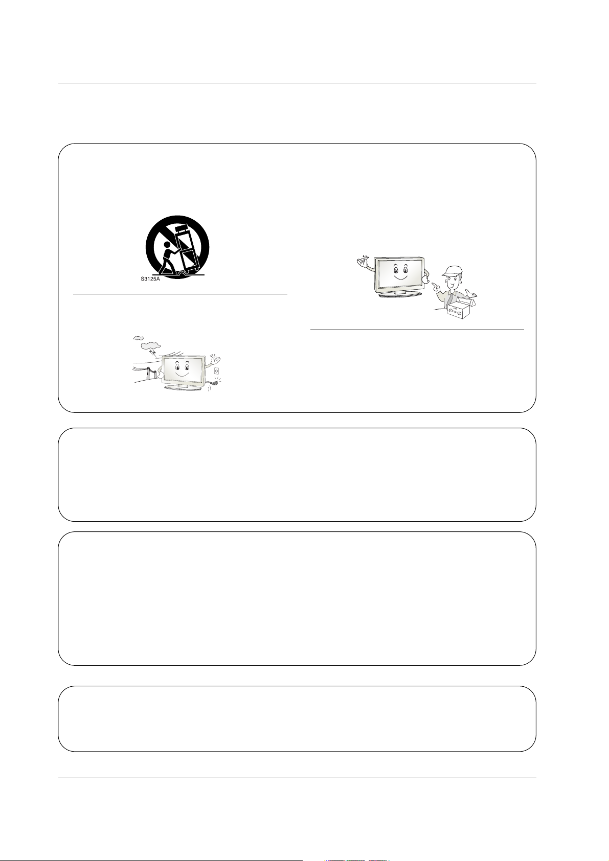
12. Use only with a cart, stand, tripod, bracket, or table
specified by the manufacturer, or sold with the apparatus. When a cart is used, use caution when moving
the cart / apparatus combination to avoid injury from
tip-over.
13. Unplug this apparatus during lightning storms or when
unused for long periods of time.
14. Refer all servicing to qualified service personnel.
Servicing is required when the apparatus has been
damaged in any way, such as power supply cord or
plug is damaged, liquid has been spilled or objects
have fallen into the apparatus, the apparatus has been
exposed to rain or moisture, does not operate normally, or has been dropped.
15. DISCONNECTING DEVICE FROM MAINS
- Mains plug is the disconnecting device. The plug
must remain readily operable.
On Disposal
a. The fluorescent lamp used in this product contains a small amount of mercury.
b. Do not dispose of this product with general household waste.
Disposal of this product must be carried out in accordance to the regulations of your local authority.
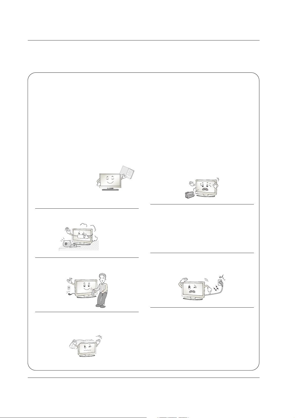
Note
- If the TV feels cold to the touch, there may be a small “flicker” when when it is turned on. This is normal, there is nothing wrong with TV.
- Some minute dot defects may be visible on the screen, appearing as tiny red, green, or blue spots. However, they have
no adverse effect on the monitor's performance.
- Avoid touching the LCD screen or holding your finger(s) against it for long periods of time. Doing so may produce some
temporary distortion effects on the screen.
CAUTION concerning the Power Cord
Most appliances recommend they be placed upon a dedicated circuit; that is, a single outlet circuit which powers only that
appliance and has no additional outlets or branch circuits. Check the specification page of this owner's manual to be certain.
Do not overload wall outlets. Overloaded wall outlets, loose or damaged wall outlets, extension cords, frayed power cords,
or damaged or cracked wire insulation are dangerous. Any of these conditions could result in electric shock or fire.
Periodically examine the cord of your appliance, and if its appearance indicates damage or deterioration, unplug it, discontinue use of the appliance, and have the cord replaced with an exact replacement part by an authorized servicer.
Protect the power cord from physical or mechanical abuse, such as being twisted, kinked, pinched, closed in a door, or
walked upon. Pay particular attention to plugs, wall outlets, and the point where the cord exits the appliance.

5
Contents
Contents
Contents
Introduction
Installation
Operation
23 Adjustments for screen Position, Clock, and Phase
23 Initializing (Reset to original factory values)
24 Turning on the TV
24 Volume Adjustment
24 Channel Selection
24 On-screen Menus Language Selection
25 Screen Menus Selection and Adjustment
26 EZ Scan (Channel Search)
26 Manual Scan
27 Channel Edit
28 DTV Signal Strength
28 Channel Label Setup
29 Main Picture Source Selection
30 EZ Picture
30 Manual Picture Control (EZ Picture-Custom Option)
31 Color Temperature Control
31 Video Reset
32 Audio Language
32 EZ SoundRite
33 EZ Sound
33 Manual Sound Control (EZ Sound-Custom Option)
34 Stereo/SAP Broadcasts Setup
34 Front Surround
35 TV Speakers On/Off Setup
35 BBE
2 Warnings
3~4 Safety Instructions
7 Controls
8 Connection Options
9~12 Remote Control Key Functions
13 Various Installation
13 Swivel Stand
14 Attaching the TV to a wall
15 How to use back cover
16 Antenna Connection
17 External AV Source Setup
17 Digital Audio Output
18 VCR Setup
19 DVD Setup
20 HDSTB Setup
21~22 PC Setup
22 Power Cord Connection
Setup Menu
Options
Video Menu
Options
Audio Menu
Options
Screen Setup
for PC mode
Basic operation
External
Equipment
Connections
Installation
Instruction

6
Contents
Reference
36 Auto Clock Setup
36 Manual Clock Setup
37 On/Off Timer Setup
37 Sleep Timer
38 Auto Off
39 Aspect Ratio Control
40 Cinema 3:2 Mode Setup
40 Caption
41 Caption/Text
42 Caption Option
42 Front Display
43~44 Parental Lock Setup
45 Watching the Double Window
45 Selecting an Input Signal Source for Double Window
45 TV Program Selection for PIP
45 Swapping the Double Window
46 Key Code
47 Programming the Remote Control
48~49 Programming Codes
50~51 Troubleshooting Checklist
52 Maintenance
52 Product Specifications
Option Menu
Features
Lock Menu Options
Double Window
Time Menu
Options
Operation
7
Introduction
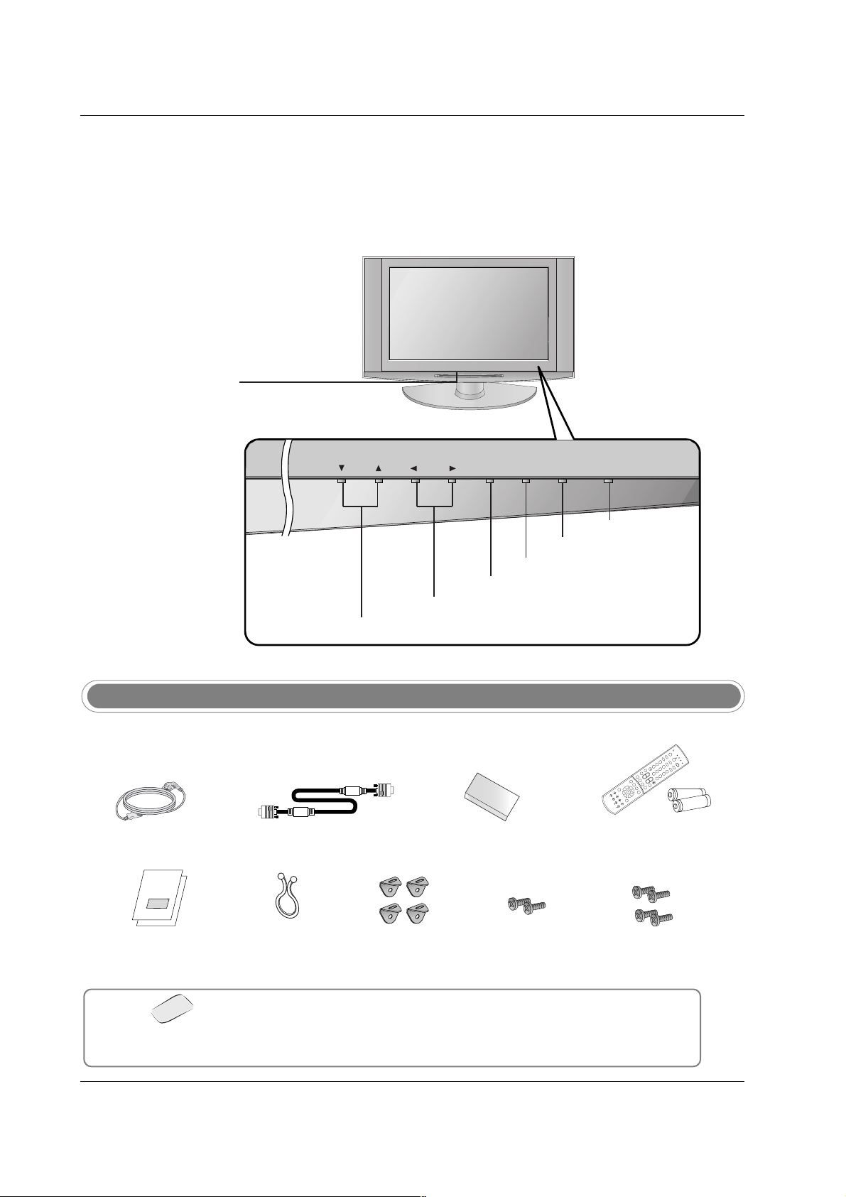
Controls
Controls
Introduction
Introduction
- This is a simplified representation of front panel.
- Here shown may be somewhat different from your TV.
CH
VOLVOL ENTERENTER INPUTINPUTMENUMENU ON/OFFON/OFF
VOLUME (F,G) Buttons
Remote Control Sensor
/Power Standby Indicator
Illuminates red when the
TV is in standby mode,
illuminates green when the
TV is switched on.
CHANNEL (E, D) Buttons
ENTER Button
ON/OFF Button
INPUT Button
MENU Button
Ensure that the following accessories are included with your TV. If any accessory is missing, please contact the
dealer from where you purchased the product.
Accessories
Owner’s Manual
/ Commercial Interface
Control Box Manual
Power Cord
D-sub 15 pin Cable
6 Shield Foams
1.5V
1.5V
1
2
3
4
5
6
7
8
9
0
T
V
M
O
D
E
P
O
W
E
R
T
V
/A
V
Z
O
O
M
I
N
F
O
V
C
R
CABLE
D
V
D
S
A
T
MUTE
SWAPPIPCH- PIPCH+
PIP
RATIO
R
E
C
O
R
D
S
T
O
P
P
A
U
S
E
R
E
W
P
L
A
Y
F
F
MENU EXIT
CC FREEZE
PIP INPUT
VOL
CH
SURF
SAP
VIDEO
S
IG
N
A
L
A
D
J
U
S
T
M
U
L
T
IM
E
D
IA
S
K
I
P
F
L
A
S
H
B
K
+
-
Remote Control /
AA Batteries
Twister Holder
Arrange the wires with
the twister holder.
2-TV Brackets,
2-Wall Brackets
2-TV Bracket Bolts 4 Bolts for security
Polishing Cloth
Polish the screen with the cloth.
* Slightly wipe stained spot on the exterior only with the polishing cloth for the
product exterior if there is stain or fingerprint on surface of the exterior.
* Do not wipe roughly when removing stain. Please be cautions of that excessive
power may cause scratch or discoloration.
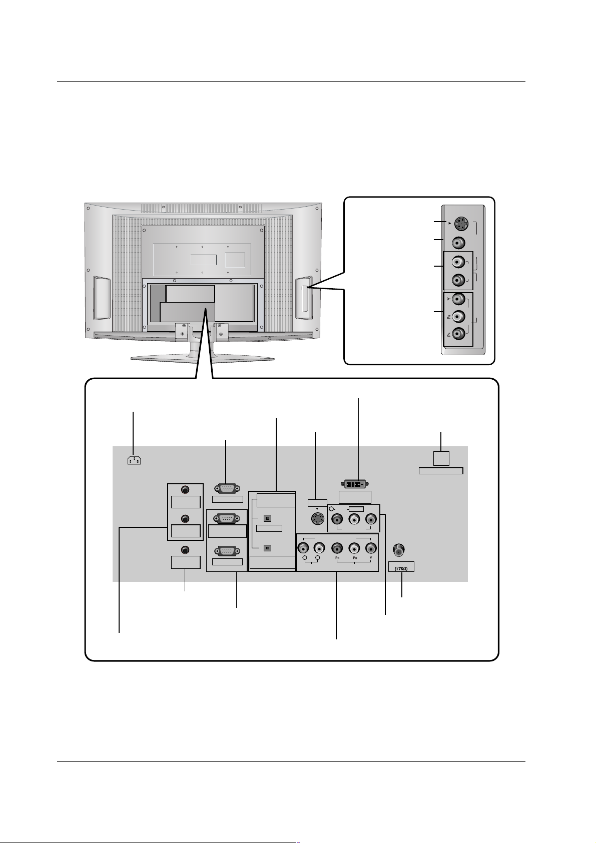
Connection Options
Connection Options
* For Service Jacks: PC INPUT2, PC AUDIO INPUT2, SPEAKER OUT, and RJP INTERFACE
Be careful not to use this jack. Just contact your dealer or service center.
8
Introduction
R
(MONO)
L VIDEO
S-VIDEO
VIDEO
AUDIO
COMPONENT 2
VIDEO 2
Antenna
PC AUDIO
INPUT2
DIGITAL AUDIO
(OPTICAL)
PC INPUT2
DVI INPUT
(PC/DTV INPUT)
L/MONO
PC INPUT1
AUDIO INPUT
AUDIO VIDEO
VIDEO INPUT
VIDEO1
COMPONENT1
RL
R
PC AUDIO
INPUT1
COMPONENT1/DVI
INPUT
SPEAKER
OUT
RS-232C INPUT
(CONTROL/SERVICE)
AC IN
S-VIDEO
RJP INTERFACE
OUTPUT
DIGITAL AUDIO OUTPUT
/ COMPONENT1/DVI INPUT
* PC INPUT2
(For service)
AUDIO/VIDEO INPUT1
COMPONENT1 (Y, P
B, PR / AUDIO INPUT)
S-VIDEO INPUT
DVI INPUT (PC/DTV INPUT)
ANTENNA INPUT
Power Cord Socket
PC AUDIO INPUT1
* PC AUDIO INPUT2 / SPEAKER OUT
(For service)
PC INPUT1
/ RS-232C INPUT (CONTROL/SERVICE)
* RJP INTERFACE
(For service)
COMPONENT2
(VIDEO Input)
AUDIO Input
VIDEO2
S-VIDEO

9
Introduction
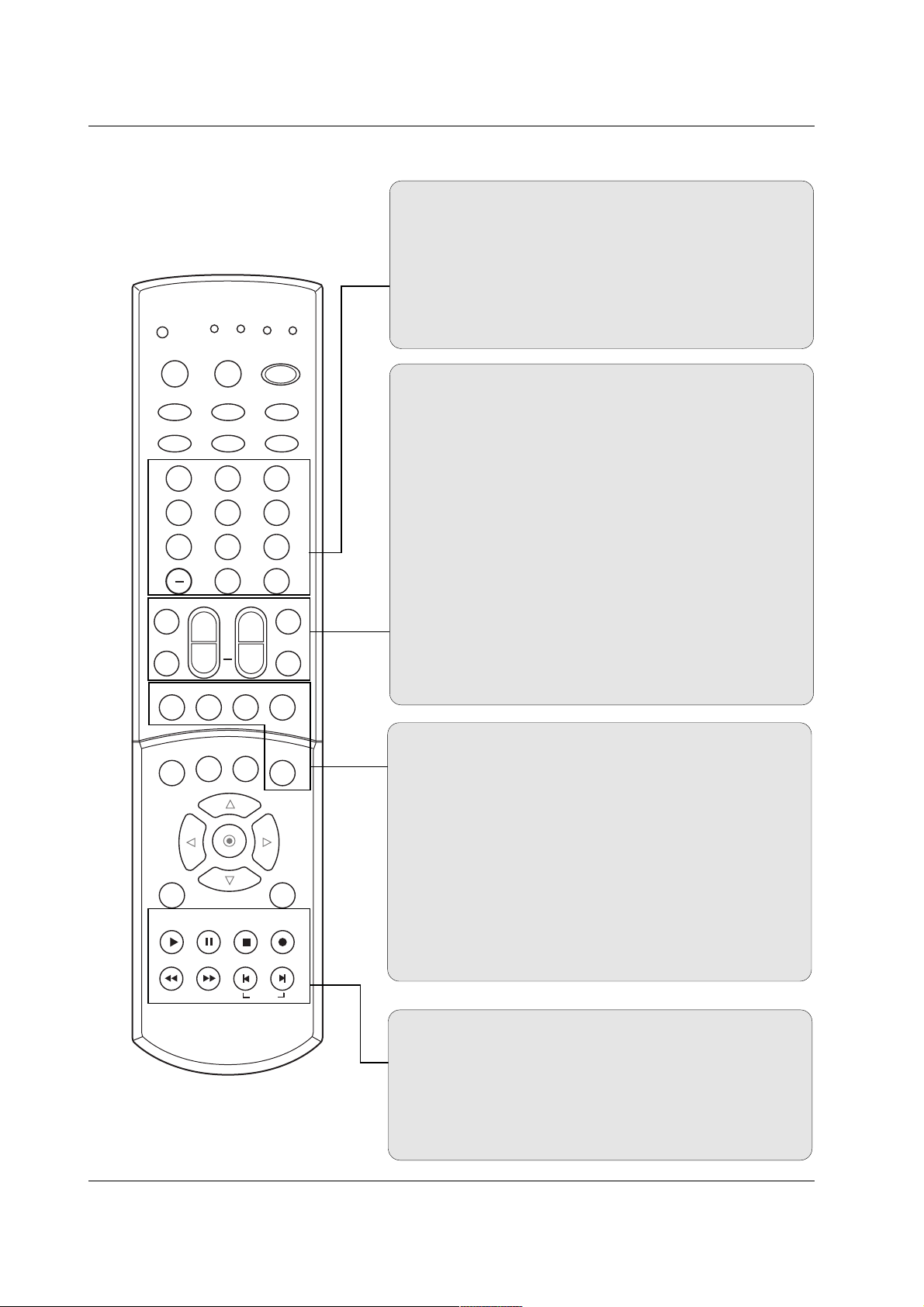
Remote Control Key Functions
Remote Control Key Functions
ADJUST
Adjusts screen position, size, and phase in PC mode.
(Refer to p.23)
MODE
Selects the remote operating mode: TV, VCR, CABLE, DVD,
HDSTB. Select other operating modes, for the remote to operate external devices.
Indicator Lights
Shows active remote mode every time any button is pressed.
INFO
When you watch the TV, displays information on top of the screen.
Not available in Component 1-2, RGB 1-2 and DVI mode.
SIGNAL
Displays the digital signal strength. (Refer to p.28)
EZ SOUND
Selects the sound appropriate for the program's character.
(Refer to p.33)
POWER
Turns your TV or any other programmed equipment on or
off, depending on mode.
1 2 3
4 5 6
7 8 9
0
TV
MODE
INFO
POWER
INPUT
EZ PIC
EZ SOUND
VCR
CABLE
DVD
HDSTB
MUTE
SWAPPIPCH- PIPCH+
PIP
RATIO
RECORD
STOP
PAUSE
REW
PLAY
FF
MENU EXIT
CC FREEZE
PIP INPUT
VOL
CH
FAV
SAP
TIMER
SIGNALADJUST
MULTIMEDIA
SKIP
FLASHBK
+
INPUT Selects:
MULTIMEDIA Selects:
Tuner AV 1 AV 2
Component 1
Component 2
RGB1
RGB2
DVI
Component 1-2 RGB1
DVI RGB2
EZ PIC
Adjusts the factory preset picture according to the room.
(Refer to p.30)
10
Introduction
1 2 3
4 5 6
7 8 9
0
TV
MODE
INFO
POWER
INPUT
EZ PIC
EZ SOUND
VCR
CABLE
DVD
HDSTB
MUTE
SWAPPIPCH- PIPCH+
PIP
RATIO
RECORD
STOP
PAUSE
REW
PLAY
FF
MENU EXIT
CC FREEZE
PIP INPUT
VOL
CH
FAV
SAP
TIMER
SIGNALADJUST
MULTIMEDIA
SKIP
FLASHBK
+
MUTE
Switches the sound on or off.
FAV
Use to scroll the Surf channel list.
SAP
Selects MTS sound: Mono, Stereo, and SAP. Change the
audio language in DTV mode. (Refer to p.34)
TIMER
Lets you select the amount of time before your TV turns
itself off automatically. (Refer to p.37)
CHANNEL UP/DOWN
Selects available channels found with EZ scan.
VOLUME UP/DOWN
Increases/decreases the sound level.
NUMBER buttons
— (DASH)
Used to enter a program number for multiple program channels such as 2-1, 2-2,etc.
FLASHBK
Return to the last channel viewed.
PIP
Switches between PIP and Double Window modes.
(Refer to p.45)
PIPCH-/PIPCH+
Changes to next higher/lower PIP channel.
(Refer to p.45)
SWAP
Exchanges the PIP/main images. (Refer to p.46)
PIP INPUT
Selects the input source for the sub picture.
(Refer to p.45)
VCR/DVD BUTTONS
Control some video cassette recorders or DVD player
("RECORD" button is not available for DVD player).
SKIP
Playing CDs: Selects songs.
Playing DVDs: Selects movie chapters.
11
Introduction
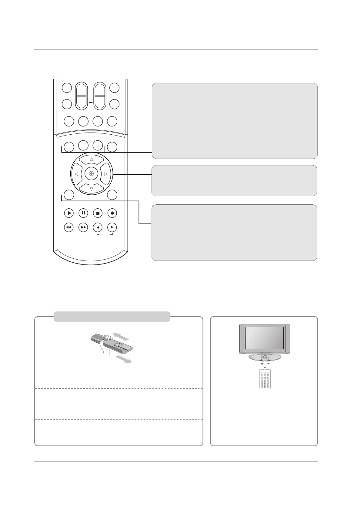
THUMBSTICK (Up/Down/Left/Right)
Allows you to navigate the on-screen menus and adjust the
system settings to your preference.
MENU
Brings up the main menu to the screen.
EXIT
Clears all on-screen displays and returns to TV viewing from
any menu.
MUTE
SWAPPIPCH- PIPCH+
PIP
RATIO
RECORD
STOP
PAUSE
REW
PLAY
FF
MENU EXIT
CC FREEZE
PIP INPUT
VOL
CH
FAV
SAP
TIMER
SKIP
+
CC
Select a closed caption mode:
Off, CC1, CC2, CC3, CC4,
Text1, Text2, Text3, or Text4. (Refer to p.41)
FREEZE
Freezes the currently-viewed picture. Main picture is frozen
in PIP/Double Window mode.
RATIO
Changes the aspect ratio. (Refer to p.39)
Installing Batteries
Open the battery compartment cover on the back side.
Insert two 1.5V AA size batteries in correct polarity (+ with
+, - with -). Don’t mix old or used batteries with new ones.
Close the cover.
* Point the remote towards the remote
control sensor of the wireless TV and
use it within about 7 meters.
* Put the used batteries into the recy-
cling bin since it can negatively affect
the environment.
1
2
3
VCR
CABLE
DVD
SAT
TV
MODE
POWER
MULTIMEDIA
TV/AV
ZOOM
INFO
SIGNALADJUST
1 2 3
4 5 6
7 8 9
FLASHBK
0
12
Introduction
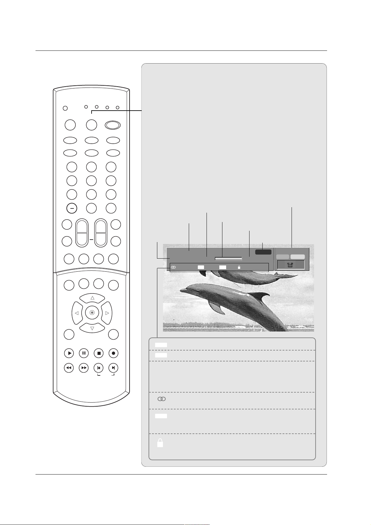
Brief Info.
Brief Info.
What is Brief Info?
: Brief Info shows the present screen information.
: On Watching with the upper Input signal, press the INFO
button.
How to use?
1. Press the INFO button to show the Brief Info on the screen.
2. Press the INFO button or EXIT button to exit.
- The INFO button does not work in Component1,
Component2, RGB1, RGB2, DVI modes.
This function works in the following mode:
• Watching TV/DTV/CATV/CADTV
• Watching AV1, AV2
Brief Info Title Test Brief Info Title Test Brief Inf..
SAT, Jan 20, 2005 7:00PM
Multilingual
Caption 1080i TV-PG D L S V
6:55AM
ANALOG 2
CC 4:3
Program title
Program start time
Banner information
Program progress bar
Program finish time
Present time
Day of week
Month, Year
The original aspect ratio of the video is 4:3
The original aspect ratio of the video is 16:9 (wide)
The video resolution is 720x480i
The video resolution is 720x480p
The video resolution is 1280x720p
The video resolution is 1920x1080i
Multilingual: The program contains two or more audio
services. Press the SAP button to select wanted Audio.
Caption: The program contains one or more caption services. Press the CC button to select wanted Closed caption.
V-Chip: The program contains V-Chip information. Refer
to the
LOCK menu: A (Age), D (Dialogue), L (Language), S
(Sex), V (Violence), FV (Fantasy Violence)
16 : 9
4 : 3
CC
480i
480p
720p
1080i
10:40AM
MONO STEREO
1 2 3
4 5 6
7 8 9
0
TV
MODE
INFO
POWER
INPUT
EZ PIC
EZ SOUND
VCR
CABLE
DVD
HDSTB
MUTE
SWAPPIPCH- PIPCH+
PIP
RATIO
RECORD
STOP
PAUSE
REW
PLAY
FF
MENU EXIT
CC FREEZE
PIP INPUT
VOL
CH
FAV
SAP
TIMER
SIGNALADJUST
MULTIMEDIA
SKIP
FLASHBK
+

13
Installation
Installation
Installation
Various Installation
For proper ventilation, allow a clearance of 4" on each side
and 2" from the wall. Detailed installation instructions are
available from your dealer, see the optional Tilt Wall
Mounting Bracket Installation and Setup Guide.
Wall Mount: Horizontal installation
Desktop Pedestal Installation
For proper ventilation, allow a clearance of 4" on each side
and the top, and 2" from the wall.
4 inches
4 inches4 inches
4 inches
4 inches
4 inches
4 inches4 inches
4 inches
14
Installation
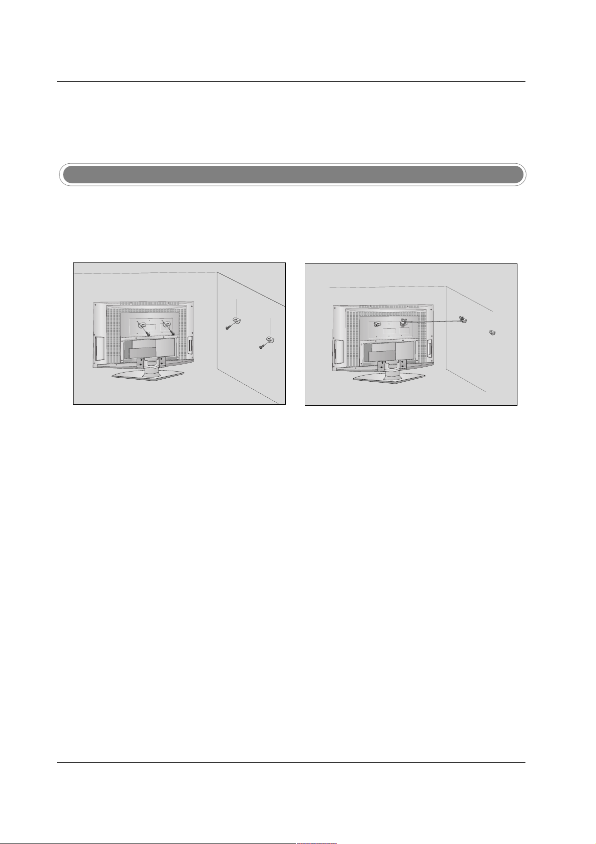
Attaching the TV to a wall
Notes
• When moving the product to another place undo the ropes first.
• Use a product holder or a cabinet that is big and strong enough for the size and weight of the product.
• To use the product safely make sure that the height of the bracket that is mounted on the wall is same
as that of the product.
Use the bracket and the bolt to fix the product to the wall as shown in the picture.
Secure the bracket with the bolt (not provided as parts of the product, must purchase separately) on
the wall.
Use a sturdy rope (not provided as parts of the product, must purchase separately) to tie the product.
It is safer to tie the rope so it becomes horizontal between the wall and the product.
1
2
3
- Set it up close to the wall so the product doesn’t fall over when it is pushed backwards.
- The instructions shown below is a safer way to set up the product, which is to fix it on the wall so the product doesn’t fall over when it is pulled in the forward direction. It will prevent the product from falling forward and hurting people. It will also prevent the product from damage caused by fall. Please make sure that children don’t climb on or
hang from the product.
2
1
3
15
Installation
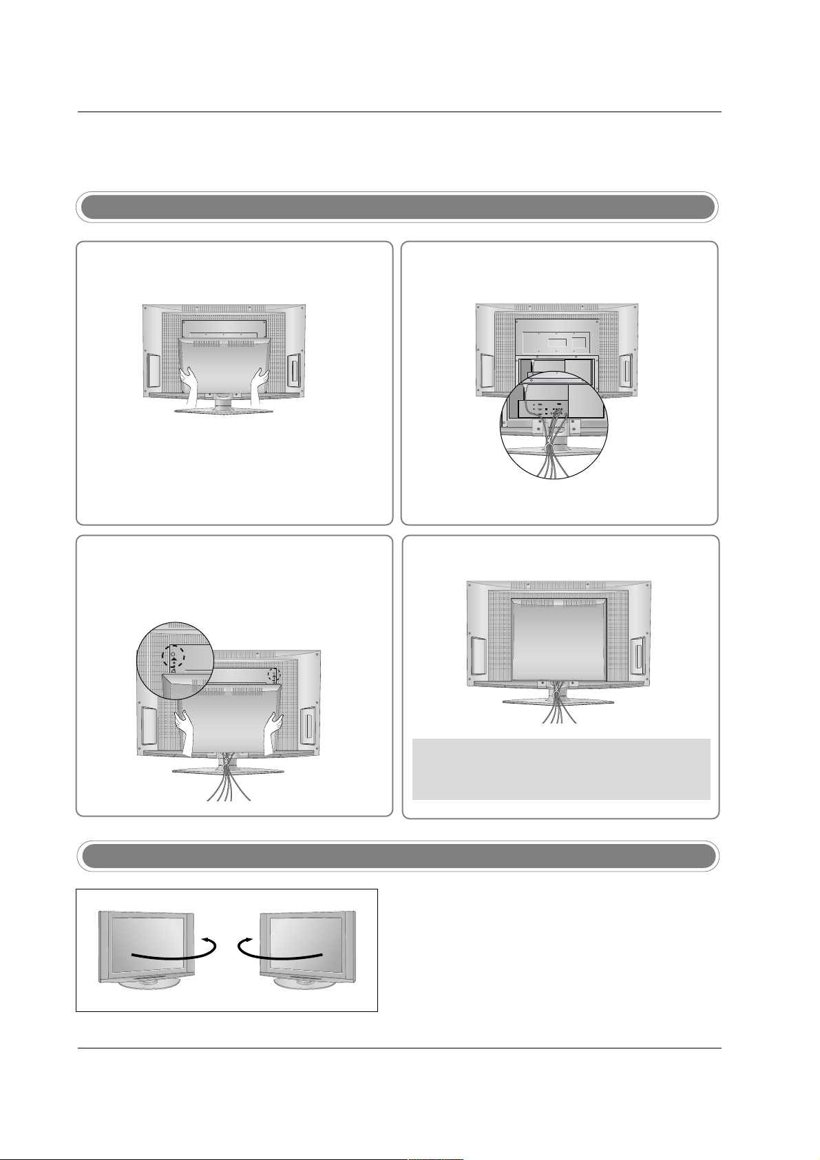
How to use back cover
- The TV can be conveniently swivelled on its stand 90°
to the left or right to provide the optimum viewing angle.
Swivel Stand
34
2
Install wires as necessary.
(To install various wires, refer to p.14~21.)
Align the holes on the TV back panel with the
protuberance on the back cover and insert.
Reinstall the cover.
Wire Arrangement
- Pull the cables through the hole on the set.
Hold the back cover with both hands and
pull it backward.
1
* Arrange the signal input cable and the power
cord by holder, as shown.

16
Installation
NOTE: If you are not sure of the type of signal(s) you are receiving, let EZ Scan complete all the channel signal-
type searches. The TV will let you know when the analog, cable, and digital channel scans are complete.
External Equipment Connections
External Equipment Connections
Antenna Connection
- Antenna or Cable Service without a Cable Box Connections.
- For optimum picture quality, adjust antenna direction if needed.
Multi-family Dwellings/Apartments
(Connect to wall antenna socket)
Single-family Dwellings /Houses
(Connect to wall jack for outdoor antenna)
Outdoor Antenna
Wall Antenna Socket
VHF Antenna
UHF Antenna
RF Coaxial Wire (75 ohm)
Turn clockwise to tighten.
• In a poor signal area to improve picture quality, purchase
and install a signal amplifier.
• If the antenna needs to be split for two TV’s, install a “2Way Signal Splitter” in the connections.
• If the antenna is not installed properly, contact your dealer for assistance.
Antenna
Bronze Wire
Be careful not to bend the bronze wire when
connecting the antenna.
Signal
Amplifier
R
L/MONO
AUDIO VIDEO
VIDEO1
COMPONENT1
L
INPUT
VIDEO INPUT
Antenna
 Loading...