

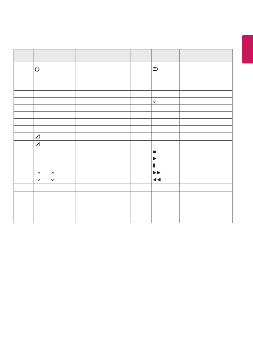
IR codes
Features may vary depending on models.
Code
(Hexa)
08
F0 TV/RAD Remote control Button 5B EXIT Remote control Button
39
30 AV MODE Remote control Button 40
79 RATIO Remote control Button 41 Remote control Button
0B INPUT Remote control Button 07 < Remote control Button
10-19 Number Key 0-9 Remote control Button 06 > Remote control Button
53 LIST Remote control Button 72 RED Remote control Button
1A Q.VIEW Remote control Button 71 GREEN Remote control Button
02
03
1E FAV Remote control Button B1 Remote control Button
AB GUIDE Remote control Button B0 Remote control Button
09 MUTE Remote control Button BA Remote control Button
00 P / PAGE Remote control Button 8E Remote control Button
01 P / PAGE Remote control Button 8F Remote control Button
20 TEXT Remote control Button 7E SIMPLINK Remote control Button
21 T.OPT(T.Option) Remote control Button 0C PORTAL Remote control Button
43 SETTINGS Remote control Button 95 ENERGY SAVING Remote control Button
45 Q.MENU Remote control Button 0E SLEEP Remote control Button
AA INFO Remote control Button 7C
Function Note
(POWER)
SUBTITLE
+
-
Remote control Button
(Power On/O)
Remote control Button 44 OK Remote control Button
Remote control Button 63 YELLOW Remote control Button
Remote control Button 61 BLUE Remote control Button
28
Code
(Hexa)
Function Note
BACK
^
Remote control Button
Remote control Button
ENGLISH
1
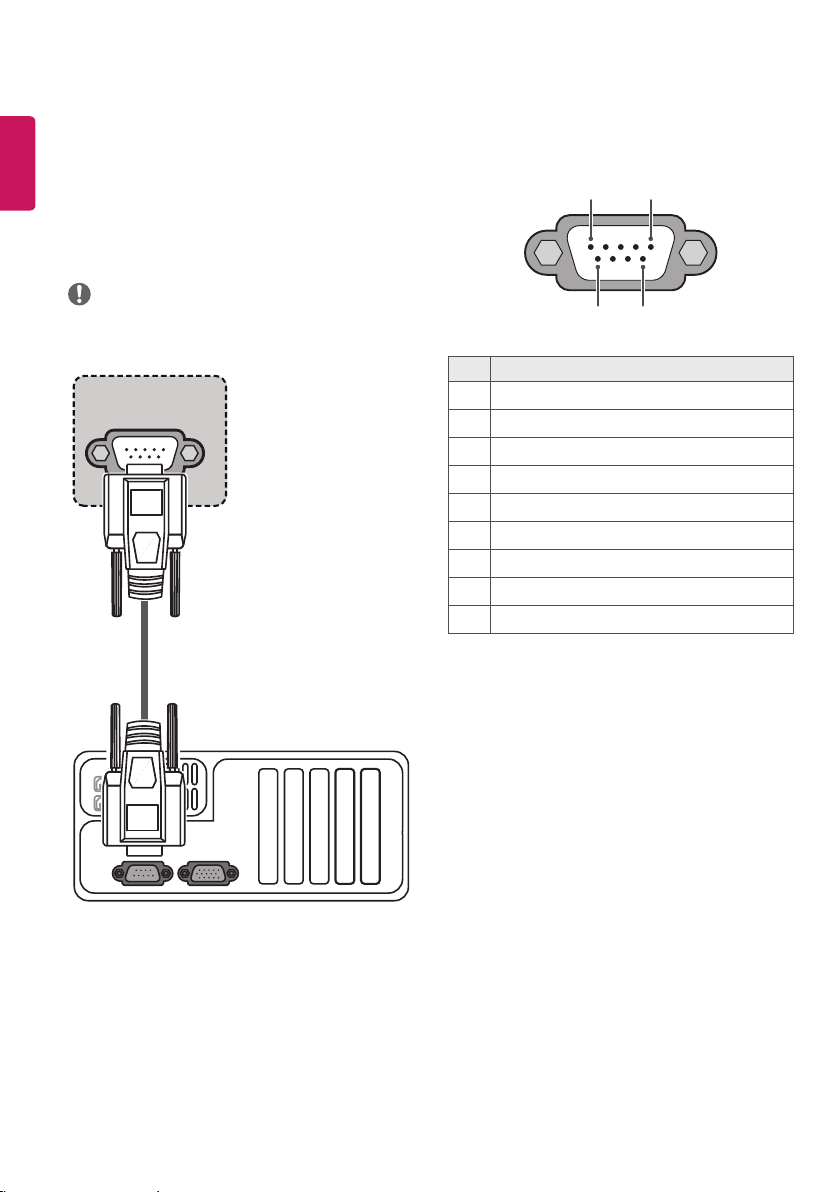
External control device setup
ENGLISH
RS-232C Setup
• Image shown may dier from your TV.
Connect the RS-232C (serial port) input jack to an external control
device (such as a computer or an A/V control system) to control the
product’s functions externally.
Connect the serial port of the control device to the RS-232C jack on the
product back panel.
NOTE
• RS-232C connection cables are not supplied with the product.
RS-232C IN
(CONTROL & SERVICE)
Type of Connector :
D-Sub 9-Pin Male
1 5
6
9
No. Pin name
1 3.5 V
2 RXD (Receive data)
3 TXD (Transmit data)
4 IR OUT from TV
5 GND
6 No Connection
7 No Connection (5 V available in some models)
8 No Connection
9 No Connection (12 V available in some models)
(*Not Provided)
2
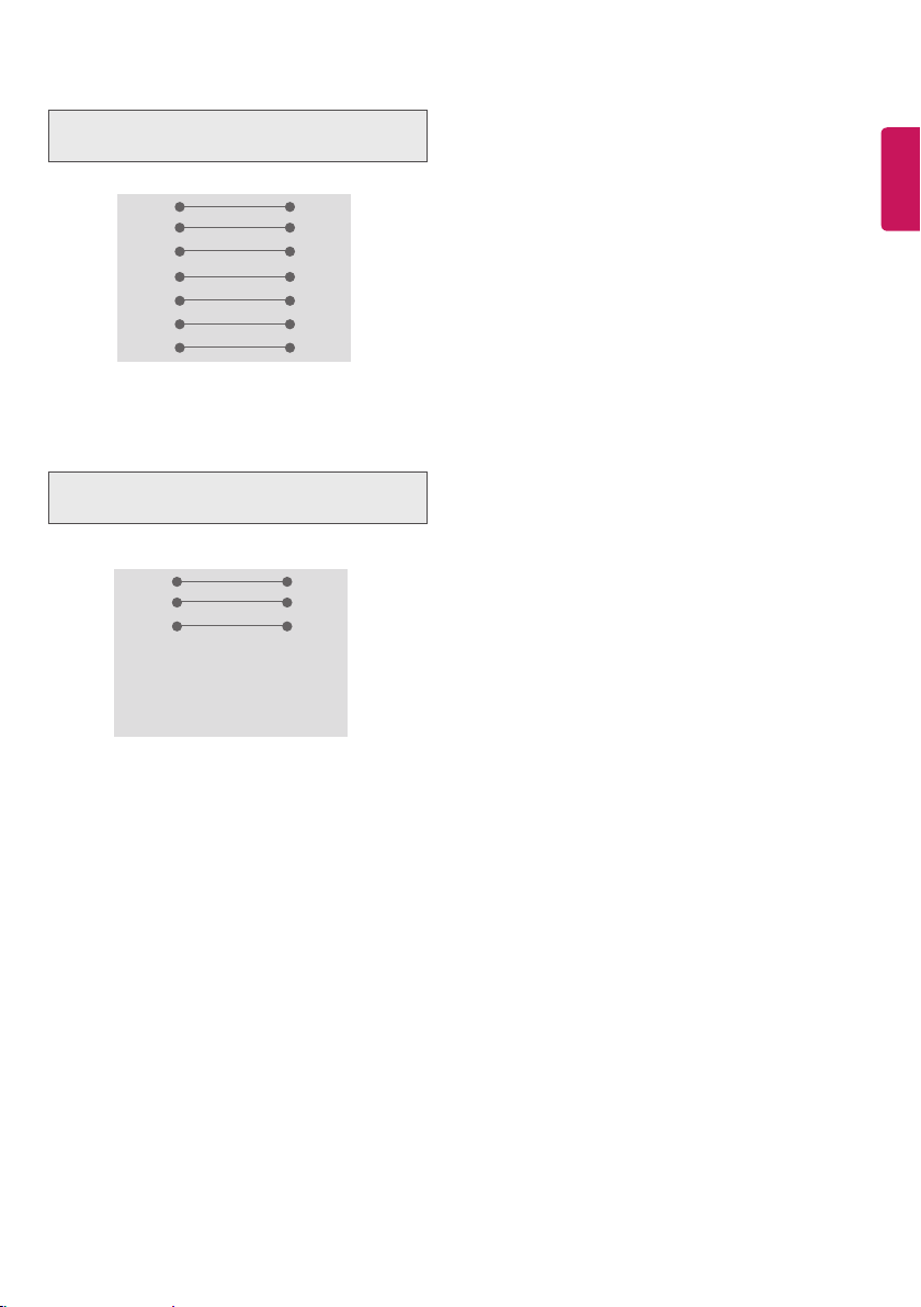
RS-232C Congurations
7-Wire Configurations
(Standard RS-232C cable)
PC TV
2 3
RXD
3 2
TXD
5 5
GND
4 6
DTR
6 4
DSR
7 8
RTS
8 7
CTS
D-Sub 9 D-Sub 9
3-Wire Configurations
(Not standard)
PC TV
2 3
RXD
3 2
TXD
5 5
GND
4 6
DTR
6 4
DSR
7 7
RTS
8 8
CTS
D-Sub 9 D-Sub 9
ENGLISH
TXD
RXD
GND
DSR
DTR
CTS
RTS
TXD
RXD
GND
DTR
DSR
RTS
CTS
Set ID
Set ID number. “Real Data Mapping”.
1 Press SETTINGS or HOME to access the main menus.
2 Press the Navigation buttons to scroll to
OPTION and press OK.
3 Press the Navigation buttons to scroll to Set ID and press OK.
4 Scroll left or right to select a set ID number and select Close. The
adjustment range is 1-99.
5 When you are nished, press EXIT.
3
 Loading...