

LG 42LT760H, 47LT660H, 22LT380H, 37LT760H, 47LT760H User Guide
...OWNER’S MANUAL
LED LCD TV
Please read this manual carefully before operating your set and retain it for future reference.
LT38**
LT64**
LT66**
LT74**
LT76**
www.lg.com
<![endif]>ENGLISH
2TABLE OF CONTENTS
TABLE OF CONTENTS
3LICENSES
3OPEN SOURCE SOFTWARE NOTICE
4INSTALLATION PROCEDURE
4ASSEMBLING AND PREPARING
4Unpacking
6 Separate purchase
7Parts and buttons
8 Lifting and moving the TV
9Setting up the TV
9- Attaching the stand
11Mounting on a table
12Mounting on a wall
14Tidying cables
15How to use Dual Lock™
16 MAKING CONNECTIONS
16Connection of TV
16Antenna connection
17HDMI connection
17Component connection
18DVI to HDMI connection
19RGB-PC connection
19Headphone connection
19Network Setup
19- Wired Network Connection
20Audio connection
20- Digital optical audio connection
20Speaker output SETUP
21USB connection
21CI module connection
22Euro Scart connection
27 MAINTENANCE
27 Cleaning your TV
27 - Screen, frame, cabinet and stand
27 - Power cord
27TROUBLESHOOTING
28CAUTION FOR USING EZSIGN
29SPECIFICATIONS
34IR CODES
35EXTERNAL CONTROL DEVICE SETUP
35RS-232C Setup
35Type of connector: D-Sub 9-Pin Male
35RS-232C Configurations
36Communication Parameters
36Command reference list
37Transmission / Receiving Protocol
 WARNING
yyIf you ignore the warning message, you may be seriously injured or there is a possibility of accident or death.
 CAUTION
yyIf you ignore the caution message, you may be slightly injured or the product may be damaged.
 NOTE
NOTE
23 REMOTE CONTROL
yyThe note helps you understand and use the product safely. Please read the note carefully before using the product.

LICENSES / OPEN SOURCE SOFTWARE NOTICE 3
LICENSES
Supported licenses may differ by model. For more information about licenses, visit www.lg.com.
Manufactured under license from Dolby Laboratories. “Dolby” and the double-D symbol are trademarks of Dolby Laboratories.
The terms HDMI and HDMI High-Definition Multimedia interface, and the HDMI logo are trademarks or registered trademarks of HDMI Licensing LLC in the United States and other countries.
ABOUT DIVX VIDEO: DivX® is a digital video format created by DivX, LLC, a subsidiary of Rovi Corporation. This is an official DivX Certified® device that plays DivX video. Visit divx.com for more information and software tools to convert your files into DivX video.
ABOUT DIVX VIDEO-ON-DEMAND: This DivX Certified® device must be registered in order to play purchased DivX Video-on-Demand (VOD) movies. To obtain your registration code, locate the DivX VOD section in your device setup menu. Go to vod. divx.com for more information on how to complete your registration.
“DivX Certified® to play DivX® video up to HD 1080p, including premium content.”
“DivX®, DivX Certified® and associated logos are trademarks of Rovi Corporation or its subsidiaries and are used under license.”
Covered by one or more of the following U.S. patents : 7,295,673; 7,460,668; 7,515,710; 7,519,274
<![endif]>ENGLISH
OPEN SOURCE SOFTWARE NOTICE
To obtain the source code under GPL, LGPL, MPL and other open source licenses, that is contained in this product, please visit http://opensource.lge.com.
In addition to the source code, all referred license terms, warranty disclaimers and copyright notices are available for download.
LG Electronics will also provide open source code to you on CD-ROM for a charge covering the cost of performing such distribution (such as the cost of media, shipping and handling) upon email request to opensource@lge.com. This offer is valid for three (3) years from the date on which you purchased the product.
<![endif]>ENGLISH
4INSTALLATION PROCEDURE / ASSEMBLING AND PREPARING
 NOTE
NOTE
yyImage shown may differ from your TV.
yyYour TV’s OSD (On Screen Display) may differ slightly from that shown in this manual.
yyThe available menus and options may differ from the input source or product model that you are using.
yyNew features may be added to this TV in the future.
yyThe TV can be placed in standby mode in order to reduce the power consumption. And the TV should be turned off if it will not be watched for some time, as this will reduce energy consumption.
yyThe energy consumed during use can be significantly reduced if the level of brightness of the picture is reduced, and this will reduce the overall running cost.
INSTALLATION PROCEDURE
1 |
Open the package and make sure all the accessories are included. |
2 |
Attach the stand to the TV set. |
3 |
Connect an external device to the TV set. |
4Make sure the network connection is available.
You can use the TV network functions only when the network connection is made. (Only LT74**, LT76**)
ASSEMBLING AND PREPARING
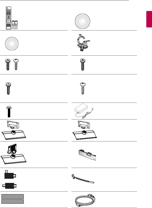
Unpacking
Check your product box for the following items. If there are any missing accessories, contact the local dealer where you purchased your product. The illustrations in this manual may differ from the actual product and item.
 CAUTION
yyDo not use any unapproved items to ensure the safety and product life span.
yyAny damages or injuries by using unapproved items are not covered by the manufacturer’s warranty. yySome models have a thin film attached on to the screen and this must not be removed.
 NOTE
NOTE
yyThe items supplied with your product may vary depending on the model.
yyProduct specifications or contents of this manual may be changed without prior notice due to upgrade of product functions.
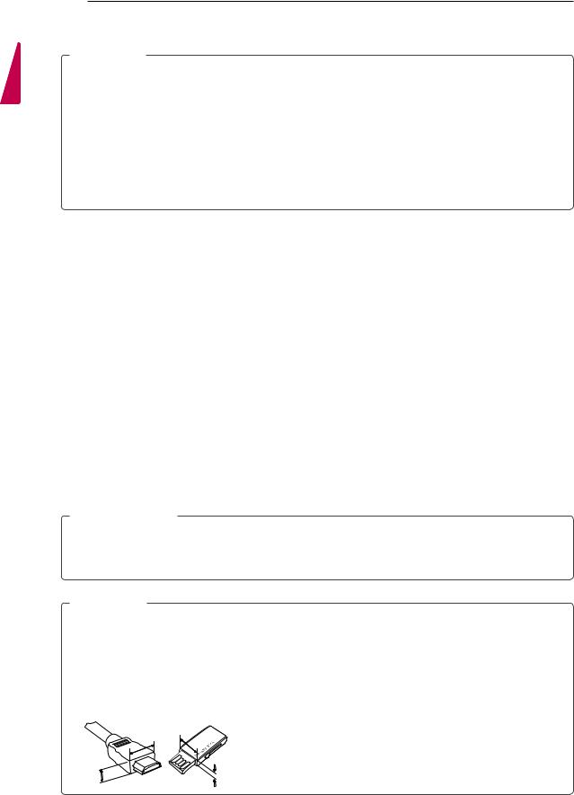
yyFor an optimal connection, HDMI cables and USB devices should have bezels less than 10 mm thick and 18 mm width. Use an extension cable that supports USB 2.0 if the USB cable or USB memory stick does not fit into your TV’s USB port.
*A  10 mm *B
  18 mm
18 mm
A A
ASSEMBLING AND PREPARING 5
|
Remote control, |
|
|
Batteries (AAA) |
Owner’s manual |
|
(See p.23, 24, 25, 26) |
|
|
|
Power Cord Holder |
|
|
(Only 32/37/42/47LT64**, |
|
|
32/37/42/47LT66**, |
|
EzSign Editor CD |
32/37/42/47LT38**, |
|
32/37/42/47LT74**, |
|
|
(Only LT640E) |
32/37/42/47LT76**) |
|
|
(See p.14) |
|
Stand Screws |
Stand Screws |
|
4 EA, M4 x 12 |
8 EA, M4 x 12 |
|
2 EA, M4 x 16 |
(Only 26LT64**, 26LT66**, |
|
(Only 22LT64**, 22LT38**) |
26LT38**) |
|
(See p.9) |
(See p.9) |
|
Stand Screws |
Desk-mount Screw |
|
8 EA, M4 x 14 |
1 EA |
|
(Only 32/37/42/47LT64**, |
(Only 32/37/42/47LT64**, |
|
32/37/42/47LT66**, |
32/37/42/47LT66**, |
|
32/37/42/47LT38**, |
32/37/42/47LT38**, |
|
32/37/42/47LT74**, |
32/37/42/47LT74**, |
|
32/37/42/47LT760*) |
32/37/42/47LT760*) |
|
(See p.10) |
(See p.11) |
|
Wall mount Screws |
DC Adapter |
|
(Only 22/26LT64**, |
|
|
4 EA, M6 x 51 |
26LT66**, 22/26LT38**) |
|
(Only 47LT****) |
(See p.16) |
|
Stand body / Stand base |
Stand body / Stand base |
|
(Only 26LT64**, 26LT66**, |
|
|
(Only 22LT64**, 22LT38**) |
26LT38**) |
|
(See p.9) |
(See p.9) |
|
Stand body / Stand base |
Protection cover |
|
(Only 32/37/42/47LT64**, |
(Only 32/37/42/47LT64**, |
|
32/37/42/47LT66**, |
32/37/42/47LT66**, |
|
32/37/42/47LT38**, |
32/37/42/47LT38**, |
|
32/37/42/47LT74**, |
32/37/42/47LT74**, |
|
32/37/42/47LT760*) |
32/37/42/47LT76**) |
|
(See p.10) |
(See p.14) |
or |
Isolator |
Cable Holder |
|
(Depending on model) |
(Depending on model) |
|
(See p.6) |
(See p.14) |
|
Dual Lock™ |
|
|
(Only LT64**, LT66**, |
Power cord |
|
LT74**, LT760*) |
|
|
(See p.15) |
(Depending on model) |
<![endif]>ENGLISH
<![endif]>ENGLISH
6ASSEMBLING AND PREPARING
Separate purchase
Separate purchase items can be changed or modified for quality improvement without any notification. Contact your dealer to buy these items.
These devices only work with certain models.
P
AN-WF100 |
AN-MR300 |
|
|
|
|
|
|
|
||
Wireless Dongle |
Magic Remote |
|
|
|
|
|
|
|||
|
Compatibility |
|
LT640E |
|
LT769H |
|
LT640H, |
LT380H, |
LT660H, |
|
|
|
|
|
|||||||
|
|
|
|
LT740H, LT760H |
||||||
|
|
|
|
|
|
|
|
|||
|
|
|
|
|
|
|
|
|
|
|
|
AN-WF100 |
|
• |
|
|
|
|
|
|
|
|
Wireless Dongle |
|
|
|
|
|
|
|
||
|
|
|
|
|
|
|
|
|
|
|
|
AN-MR300 |
|
|
|
• |
|
|
|
|
|
|
Magic Remote |
|
|
|
|
|
|
|
||
|
|
|
|
|
|
|
|
|
|
|
 NOTE
NOTE
yyAntenna Isolator Installation Guide
-- Use this to install TV in a place where there is a voltage difference between TV Set and GND of antenna signal.
»» If there is a voltage difference between TV Set and GND of antenna signal, the antenna contact might be heated and excessive heat might cause an accident.
-- You can improve the safety when watching TV by efficiently removing power voltage from TV antenna. It is recommended to mount the isolator to the wall. If it cannot be mounted to the wall, mount it on the TV. Avoid disconnecting the antenna Isolator after installation.
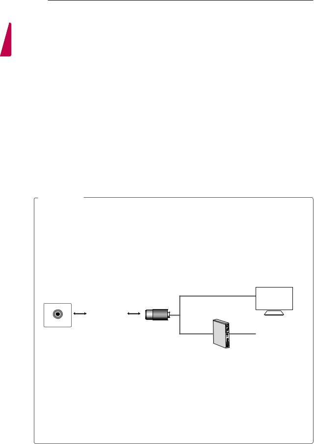
-- Before starting, be sure that the TV antenna is connected.
1. Connect to TV.
Wall |
|
ANTENNA/ |
or |
|
Cable / Antenna |
Isolator |
2. Connect to Set-Top box.
Connect one end of the isolator to cable/antenna jack and the other to TV set or set-top box.
“Equipment connected to the protective earthing of the building installation through the mains connection or through other equipment with a connection to protective earthing - and to a cable distribution system using coaxial cable, may in some circumstances create a fire hazard. Connection to a cable distribution system has therefore to be provided through a device providing electrical isolation below a certain frequency range (galvanic isolator, see EN 60728-11)”
When applying the RF Isolator, a slight loss of signal sensitivity can occur.
ASSEMBLING AND PREPARING 7
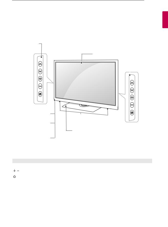
Parts and buttons
(Only 32/37/42/47LT64**, 32/37/42/47LT66**, 32/37/42/47LT38**, 32/37/42/47LT74**, 32/37/42/47LT76**)
Remote control sensor
Power Indicator (Can be adjusted using the Power Indicator in the OPTION -menu.)
Clock LED
(Only LT64**, LT66**, LT74**, LT760*)
Screen
(Only 22/26LT64**, 26LT66**, 22/26LT38**,  26LT769*)
Speakers
Stand
(Only LT64**, LT66**, LT38**,
LT74**, LT760*)
Button |
Description |
|
Scrolls through the saved programmes. |
|
|
|
Adjusts the volume level. |
|
|
|
Turns the power on or off. |
|
|
<![endif]>ENGLISH
<![endif]>ENGLISH
8ASSEMBLING AND PREPARING
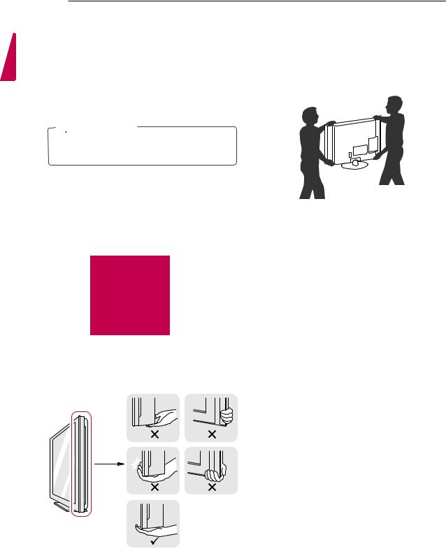
Lifting and moving the TV
When moving or lifting the TV, read the following to prevent the TV from being scratched or damaged and for safe transportation regardless of its type and size.
 CAUTION
yyAvoid touching the screen at all times, as this may result in damage to the screen.
yyIt is recommended to move the TV in the box or packing material that the TV originally came in.
yyBefore moving or lifting the TV, disconnect the power cord and all cables.
yyWhen holding the TV, the screen should face away from you to avoid damage.
yyHold the top and bottom of the TV frame firmly. Make sure not to hold the transparent part, speaker, or speaker grill area.
yyWhen transporting a large TV, there should be at least 2 people.
yyWhen transporting the TV by hand, hold the TV as shown in the following illustration.
yyWhen transporting the TV, do not expose the TV to jolts or excessive vibration.
yyWhen transporting the TV, keep the TV upright, never turn the TV on its side or tilt towards the left or right.
yyDo not apply excessive pressure that may cause flexing / bending of the frame chassis and damage to the screen.

ASSEMBLING AND PREPARING 9
Setting up the TV
Put your TV on a pedestal stand and mount the TV on a table or wall.
Attaching the stand
(Only 22/26LT64**, 26LT66**, 22/26LT38**)
1 |
3 |
|
M4 x 12 |
||
|
||
|
(Only 22LT64**, 22LT38**) |
|
|
4 EA |
|
Stand Body |
|
|
|
Front |
Stand Base
M4 x 16
2 EA
Top View
2
(Only 26LT64**, 26LT66**, 26LT38**)
<![endif]>ENGLISH
 M4 x 12
  4 EA
4 EA
<![endif]>ENGLISH
10 ASSEMBLING AND PREPARING
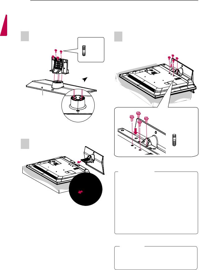
(Only 32/37/42/47LT64**, 32/37/42/47LT66**, 32/37/42/47LT38**, 32/37/42/47LT74**, 32/37/42/47LT760*)
1 |
3 |
 M4 x 14
  4 EA
4 EA
Stand Body 


 Front
Front
Stand Base
Top View
2
 M4 x 14
  4 EA
4 EA
 CAUTION
yyWhen attaching the stand to the TV set, place the screen facing down on a
cushioned table or flat surface to protect the screen from scratches.
yyMake sure that the screws are fastened completely. (If they are not fastened securely enough, the TV may tilt forward after being installed.)
Do not fasten the screws with too much force; otherwise they may be worn out and get loosened.
 NOTE
NOTE
yyRemove the stand before installing the TV on a wall mount by performing the stand attachment in reverse.
ASSEMBLING AND PREPARING 11
Mounting on a table |
|
||
|
Securing the TV to a table |
|
|
1Lift and tilt the TV into its upright position on a table.
-Leave a 10 cm (minimum) space from the wall for proper ventilation.
Fix the TV to a table to prevent from tilting forward, damage, and potential injury.
Mount the TV on a table, and then insert and tighten the supplied screw on the rear of the stand.
(Only 32/37/42/47LT64**, 32/37/42/47LT66**, 32/37/42/47LT38**, 32/37/42/47LT74**,
32/37/42/47LT760*)
<![endif]>ENGLISH
2 Connect the power cord to a wall outlet.
CAUTION
yyDo not place the TV near or on sources of heat, as this may result in fire or other damage.
Attaching the TV to a table
Image shown may differ from your TV.
The TV must be attached to desk so it cannot be pulled in a forward/backward direction, potentially causing injury or damaging the pro duct.
(Only 32/37/42/47LT64**, 32/37/42/47LT66**, 32/37/42/47LT38**, 32/37/42/47LT74**, 32/37/42/47LT760*)
4-Screws
(not provided as parts of the product) Stand
Table
WARNING
yyTo prevent TV from falling over, the TV should be securely attached to the floor/ wall per installation instructions. Tipping, shaking, or rocking the TV may cause injury.
Adjusting the angle of the TV to suit view
(Only LT64**, LT66**, LT38**, LT74**, LT760*)
Swivel 90 degrees to the left or right and adjust the angle of the TV to suit your view.
90 |
|
90 |
|
|
|
CAUTION
yyWhen adjusting the angle of the product, watch out for your fingers.
»» Personal injury may occur if hands or fingers are pinched. If the product is tilted too much, it may fall, causing damage or injury.
Screws: M5 x L (*L: Table depth + 8-10 mm) ex) Table depth: 15 mm, Screw: M5 x 25

<![endif]>ENGLISH
12 ASSEMBLING AND PREPARING
Securing the TV to a wall
(This feature is not available for all models.)
1 |
Insert and tighten the eye |
and bolts on the back of the TV.
-- If there are bolts inserted at the eye-bolts position, remove the bolts first.
2Mount the wall brackets with the bolts to the wall.
Match the location of the wall bracket and the
eye-bolts on the rear of the TV.
3Connect the eye-bolts and wall brackets tightly with a sturdy rope.
Make sure to keep the rope horizontal with the flat surface.
CAUTION
yyMake sure that children do not climb on or hang on the TV.
NOTE
yyUse a platform or cabinet that is strong and large enough to support the TV securely. yyBrackets, bolts and ropes are not provided. You can obtain additional accessories from
your local dealer.
Using the Kensington security system
(This feature is not available for all models.)
The Kensington security system connector is located at the rear of the TV. For more information of installation and using, refer to the manual provided with the Kensington security system or visit http://www.kensington.com.
Connect the Kensington security system cable between the TV
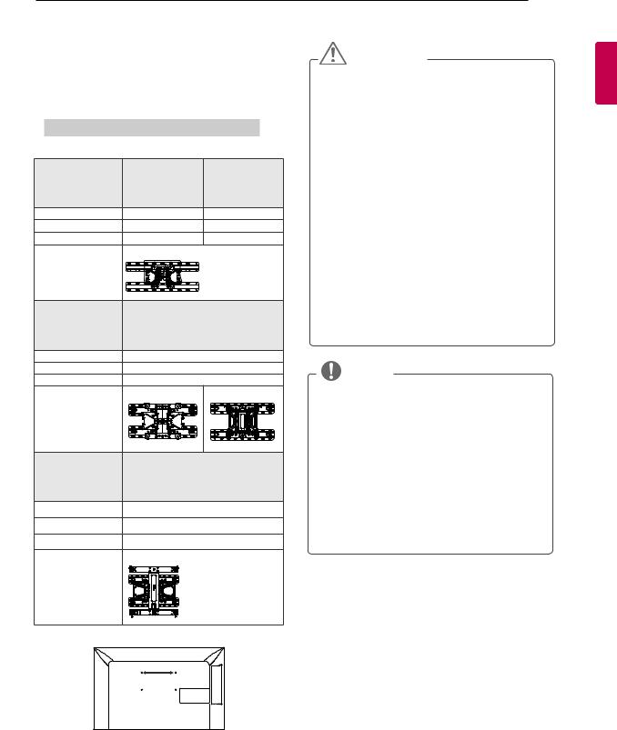
Mounting on a wall
Attach an optional wall mount bracket at the rear of the TV carefully and install the wall mount bracket on a solid wall perpendicular to the floor. When you attach the TV to other building materials, please contact qualified personnel.
LG recommends that wall mounting be performed by a qualified professional installer.
10 cm
10 cm  10 cm
10 cm
cm
|
|
|
ASSEMBLING AND PREPARING 13 |
|
Make sure to use screws and wall mount |
CAUTION |
|||
bracket that meet the VESA standard. Standard |
||||
dimensions for the wall mount kits are described in |
yyDisconnect the power first, and then move |
|||
the following table. |
|
|||
|
or install the TV. Otherwise electric shock |
|||
|
|
|
||
|
|
|
may occur. |
|
Separate purchase (Wall Mounting Bracket) |
yyIf you install the TV on a ceiling or slanted |
|||
wall, it may fall and result in severe injury. |
||||
|
|
|
||
|
|
|
Use an authorized LG wall mount bracket |
|
Model |
22/26LT64**, |
32LT64**, |
and contact the local dealer or qualified |
|
|
22/26LT38**, |
32LT66**, |
personnel. |
|
|
26LT66** |
32LT38** |
yyDo not over tighten the screws as this may |
|
|
26LT76** |
32LT74** |
cause damage to the TV and void your |
|
|
|
32LT76**, |
||
VESA |
100 x 100 |
200 x 100 |
warranty. |
|
Standard screw |
M4 |
M4 |
yyUse the screws and wall mount bracket that |
|
Number of screws 4 |
4 |
meet the VESA standard. Any damages |
||
Wall mount |
LSW100B(G) |
|
or injuries by misuse or using an improper |
|
bracket |
|
|
accessory are not covered by the warranty. |
|
|
|
|
yyOn the 47LT**** models, use M6 x 51 |
|
|
|
|
screws. |
|
Model |
37/42LT64**, |
|
yyIf you use the wall mounting bracket, do |
|
|
37/42LT66**, |
|
not fix screw into holes for assembling the |
|
|
37/42LT38**, |
|
stand. |
|
|
37/42LT74**, |
|
|
|
VESA |
37/42LT76** |
|
|
|
200 x 200 |
|
|
||
Standard screw |
M6 |
|
NOTE |
|
Number of screws 4 |
|
|||
Wall mount |
LSW200B(G) |
LSW220BX |
yyUse the screws that are listed on the VESA |
|
bracket |
|
|
||
|
|
standard screw specifications. |
||
|
|
|
||
|
|
|
yyThe wall mount kit includes an installation |
|
|
|
|
manual and necessary parts. |
|
Model |
47LT64**, |
|
yyThe wall mount bracket is not provided. You |
|
|
can obtain additional accessories from your |
|||
|
47LT66**, |
|
local dealer. |
|
|
47LT38**, |
|
||
|
47LT74**, |
|
yyThe length of screws may differ depending |
|
VESA |
47LT76** |
|
on the wall mount. Make sure to use the |
|
400 x 400 |
|
|||
|
proper length. |
|||
Standard screw |
M6 |
|
||
|
yyFor more information, refer to the manual |
|||
Number of screws 4 |
|
|||
|
supplied with the wall mount. |
|||
Wall mount |
LSW420BX |
|
|
|
bracket |
|
|
|
|
A
B
<![endif]>ENGLISH
 Loading...