

LG 49LT570H, 32LT570H, 43LT570H User Manual

32LT570H
43LT570H
49LT570H
Lodging Guest Interactive Pro:Centric ® TVs
Commercial Mode Setup Guide
Note: Selected features shown in this guide may not be available on all models.
EXPERIENCED INSTALLER
EZ-Manager Wizard
pages 12 – 20
Custom Master TV Setup
pages 36 – 38
Cloning Procedures
pages 39 – 44
© Copyright 2019 LG Electronics U.S.A., Inc.
P/N: 206-4340 (Rev A)

For Customer Support/Service, please call:
1-888-865-3026
The latest product information and documentation is
available online at:
www.lg.com/us/business
MODEL and SERIAL NUMBER
The model and serial numbers of this TV are located on the
back of the cabinet. For future reference, LG suggests that you
record those numbers here:
Model No._________________ Serial No._______________
WARNING
RISK OF ELECTRIC SHOCK
DO NOT OPEN
WARNING:
TO REDUCE THE RISK OF ELECTRIC SHOCK DO NOT REMOVE COVER (OR BACK). NO USERSERVICEABLE PARTS INSIDE. REFER TO QUALIFIED SERVICE PERSONNEL.
The lightning flash with arrowhead symbol, within an equilateral triangle, is intended to alert the user to the
presence of uninsulated “dangerous voltage” within the product’s enclosure that may be of sufficient magnitude
to constitute a risk of electric shock to persons.
The exclamation point within an equilateral triangle is intended to alert the user to the presence of important
operating and maintenance (servicing) instructions in the literature accompanying the appliance.
WARNING:
TO PREVENT FIRE OR SHOCK HAZARDS, DO NOT EXPOSE THIS PRODUCT TO RAIN OR MOISTURE.
WARNING:
This product contains chemicals known to the State of California to cause cancer and birth defects or other
reproductive harm. Wash hands after handling.
NOTE TO CABLE/TV INSTALLER:
This reminder is provided to call the cable TV system installer’s attention to Article 820-40 of the National Electrical Code
(U.S.A.). The code provides guidelines for proper grounding and, in particular, specifies that the cable ground shall be
connected to the grounding system of the building, as close to the point of the cable entry as practical.
REGULATORY INFORMATION:
This equipment has been tested and found to comply with the limits for a Class B digital device, pursuant to Part 15 of the
FCC Rules. These limits are designed to provide reasonable protection against harmful interference when the equipment is
operated in a residential installation. This equipment generates, uses and can radiate radio frequency energy and, if not
installed and used in accordance with the instruction manual, may cause harmful interference to radio communications.
However, there is no guarantee that interference will not occur in a particular installation. If this equipment does cause
harmful interference to radio or television reception, which can be determined by turning the equipment off and on, the user
is encouraged to try to correct the interference by one or more of the following measures:
• Reorient or relocate the receiving antenna.
• Increase the separation between the equipment and receiver.
• Connect the equipment to an outlet on a circuit different from that to which the receiver is connected.
• Consult the dealer or an experienced radio/TV technician for help.
CAUTION:
Do not attempt to modify this product in any way without written authorization from LG Electronics U.S.A., Inc.
Unauthorized modification could void the user’s authority to operate this product.
COMPLIANCE:
The responsible party for this product’s compliance is: LG Electronics U.S.A., Inc.
1000 Sylvan Avenue, Englewood Cliffs, NJ 07632, USA • Phone: 1-201-816-2000
Marketed and Distributed in the United States by LG Electronics U.S.A., Inc.
1000 Sylvan Avenue, Englewood Cliffs, NJ 07632
2
© Copyright 2019 LG Electronics U.S.A., Inc.
206-4340
IMPORTANT SAFETY INSTRUCTIONS
1. Read these instructions.
2. Keep these instructions.
3. Heed all warnings.
4. Follow all instructions.
5. Do not use this apparatus near water.
6. Clean only with dry cloth.
7. Do not block any ventilation openings. Install in accordance with the manufacturer’s instructions.
8. Do not install near any heat sources, such as radiators,
heat registers, stoves, or other apparatus (including
amplifiers) that produce heat.
9. Do not defeat the safety purpose of the polarized or
grounding-type plug. A polarized plug has two blades
with one wider than the other. A grounding-type plug
has two blades and a third grounding prong. The wide
blade or the third prong are provided for your safety. If
the provided plug does not fit into your outlet, consult
an electrician for replacement of the obsolete outlet.
10. Protect the power cord from being walked on or pinched,
particularly at plugs, convenience receptacles, and the
point where it exits from the apparatus.
11. Only use attachments/accessories specified by the
manufacturer.
12. Use only with the cart, stand, tripod, bracket, or table
specified by the manufacturer or sold with the apparatus.
When a cart is used, use caution when moving the cart/
apparatus combination in order to avoid injury from
tip-over.
PORTABLE CART WARNING
13.
Refer all servicing to qualied service personnel.
Servicing is required when the apparatus has been
damaged in any way, such as power-supply cord or
plug is damaged, liquid has been spilled or objects
have fallen into the apparatus, the apparatus has been
exposed to rain or moisture, does not operate normally,
or has been dropped.
14. Never touch this apparatus or antenna during a thunder or
lightning storm.
15. Do not apply pressure on or scratch the TV panel during
handling. Do not press against the TV panel with your hand
or a sharp object such as a nail, pencil, or pen.
16. Power Cord
Caution: Check the TV specifications in the Owner’s
Manual to determine power requirements.
Periodically examine the cord of your appliance, and if its
appearance indicates damage or deterioration, unplug it,
discontinue use of the appliance, and have the cord replaced
with an exact replacement part by an authorized servicer.
Protect the power cord from physical or mechanical abuse,
such as twisting, kinking, or pinching or being closed in a
door or walked upon. Pay particular attention to plugs, wall
outlets, and the point where the cord exits the appliance.
Do not use a damaged or loose power cord. Be sure to grasp
the plug when unplugging the power cord. Do not pull on the
power cord to unplug the TV.
Do not stick metal objects or any other conductive material
into the power cord. Do not touch the end of the power cord
while it is plugged in.
17. Overloading
Do not connect too many appliances to the same AC power
outlet as this could result in fire or electric shock. Do not
overload wall outlets. Overloaded wall outlets, loose or
damaged wall outlets, extension cords, frayed power cords,
or damaged or cracked wire insulation are dangerous. Any of
these conditions could result in re or electric shock.
18. Outdoor Use/Wet Location
Warning: To reduce the risk of re or electrical
shock, do not expose this product to rain,
moisture or other liquids.
Do not touch the TV with wet hands. Do not install this product
near ammable objects such as gasoline or candles or expose
the TV to direct air conditioning.
Do not expose to dripping or splashing and do not place
objects lled with liquids, such as vases, cups, etc., on or over
the apparatus (e.g., on shelves above the unit).
19. Grounding
(Except for devices that are not grounded) Ensure that you
connect the earth ground wire to prevent possible electric
shock (i.e., a TV with a three-prong grounded AC plug must be
connected to a three-prong grounded AC outlet). If grounding
methods are not possible, have a qualied electrician install
a separate circuit breaker. Do not try to ground the unit by
connecting it to telephone wires, lightning rods, or gas pipes.
20. Disconnect Device
The power plug is the disconnecting device. The power plug
must remain readily accessible.
As long as this unit is connected to the AC wall outlet, it is not
disconnected from the AC power source even if the unit is
turned off.
(Continued on next page)
206-4340
3
IMPORTANT SAFETY INSTRUCTIONS
(Continued from previous page)
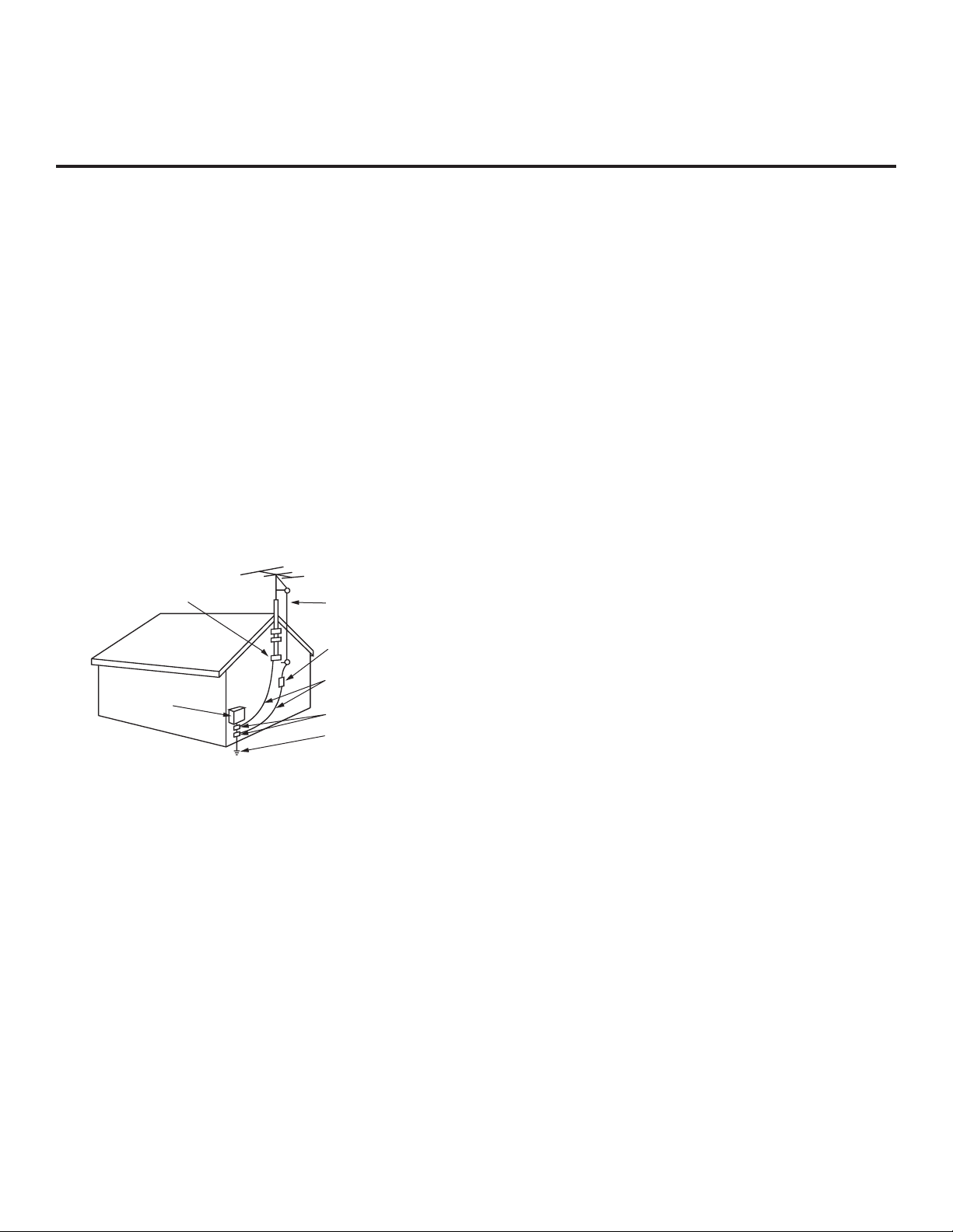
21. Outdoor Antenna Grounding
If an outside antenna or cable system is connected to the
product, follow the precautions below.
An outdoor antenna system should not be located in the
vicinity of overhead power lines or other electric light or power
circuits or where it can come into contact with such power
lines or circuits as death or serious injury can occur.
Be sure the antenna system is grounded so as to provide
some protection against voltage surges and built-up static
charges.
Article 810 of the National Electrical Code (NEC) in the U.S.A.
provides information with respect to proper grounding of the
mast and supporting structure, grounding of the lead-in wire
to an antenna-discharge unit, size of grounding conductors,
location of antenna-discharge unit, connection to grounding
electrodes, and requirements for the grounding electrode.
Antenna Grounding According to NEC, ANSI/NFPA 70
Ground Clamp
Electric Service
Equipment
Antenna Lead in Wire
Antenna Discharge Unit
(NEC Section 810-20)
Grounding Conductor
(NEC Section 810-21)
Ground Clamps
Power Service Grounding
Electrode System (NEC
Art 250, Part H)
22. Cleaning
When cleaning, unplug the power cord and wipe gently with
a soft cloth to prevent scratching. Do not spray water or other
liquids directly on the TV as electric shock may occur. Do not
clean with chemicals such as alcohol, thinners or benzene.
23. Transporting Product
Make sure the TV is turned off and unplugged and that all
cables have been removed. It may take two or more people
to carry larger TVs. Do not press against or put stress on the
front panel of the TV.
24. Ventilation
Install the TV where there is proper ventilation. Do not install
in a conned space such as a bookcase. Do not cover the TV
with cloth or other materials (e.g., plastic) while it is plugged
in. Do not install in excessively dusty places.
25. If you smell smoke or other odors coming from the TV or
hear strange sounds, unplug the power cord, and contact an
authorized service center.
26. Keep the product away from direct sunlight.
27. When mounting a TV on the wall, make sure that none of the
electrical cabling bears any of the weight of the TV. Install in
accordance with the manufacturer’s instructions.
28. Do not install this product on a wall if it could be exposed to
oil or oil mist. This may damage the product and cause it to
fall.
29. Do not allow an impact shock or any objects to fall into the
product, and do not drop objects onto the screen.
30. Do not touch the ventilation openings, as they may become
hot while the TV is operating. This does not affect the performance of the product or cause defects in the product.
31. Do not use high voltage electrical equipment near the TV
(e.g., a bug zapper). This may result in product malfunction.
32. Dot Defect
This panel is an advanced product that contains millions of
pixels. In a very few cases, you could see ne dots on the
screen while you are viewing the TV. Those dots are deactivated pixels and do not affect the performance and reliability
of the TV.
33. Generated Sound
“Cracking”: A cracking noise that occurs while the TV is
on or when it is turned off is generated by plastic thermal
contraction due to temperature and humidity. This noise is
common for products where thermal deformation is required.
Electrical circuit humming/panel buzzing: A low level noise is
generated from a high-speed switching circuit, which supplies
a large amount of current to operate a product. It varies
depending on the product. This generated sound does not
affect the performance and reliability of the product.
34. If the TV feels cold to the touch, there may be a small “icker”
when it is turned on. This is normal; there is nothing wrong
with the TV. Some minute dot defects may be visible on the
screen, appearing as tiny red, green, or blue spots. However,
they have no adverse effect on the TV’s performance. Avoid
touching the screen or holding your nger(s) against it for
long periods of time. Doing so may produce some temporary
distortion effects on the screen.
35. Displaying a still image for a prolonged period of time may
cause image burn-in. Avoid displaying a xed image on the
TV screen for an extended length of time.
4
206-4340

Table of Contents
Safety Warnings .................................. 2
Important Safety Instructions . . . . . . . . . . . . . . . . . . . . . . 3 – 4
Table of Contents ................................. 5
Commercial Mode Overview .....................6 – 9
Setup Checklist ................................. 6
Pass-through Mode.............................. 6
FTG Mode..................................... 7
Determining the TV Operating Mode ................ 9
Pro:Centric Operation ........................10 – 11
Interactive Menu Features ....................... 10
Interactive Menu Navigation ...................... 10
Pro:Centric Java Application Setup .................11
EZ-Manager Wizard ..........................12
Before You Begin .............................. 12
Initiate Configuration or Exit the EZ-Manager Wizard .. 12
TV Configuration Options.......................... 13
Zone and Room Number Assignments .............. 14
Configure Pro:Centric Settings .................... 15
USB Configuration ............................. 18
Ez Download Utility ..........................21
Before You Begin .............................. 21
Accessing and Using the Ez Download Utility ........ 21
Installer Menu ...............................25 – 35
Accessing the Installer Menu ..................... 25
Navigating Within the Installer Menu ............... 26
Modifying Installer Menu Settings.................. 26
Exiting the Installer Menu and Activating Settings ..... 26
Detailed Descriptions of Installer Menu Items ........ 29
Custom Master TV Setup......................36
Before You Begin .............................. 36
Clonable TV Setup Menu Features ................ 36
Custom Master TV Setup Procedure ............... 37
Cloning Procedures ..........................39
Exporting a Clone File .......................... 39
Importing a Clone File........................... 41
Cloud Configuration Tool Overview .............45 – 50
– 20
– 24
– 38
–
44
Creating an FTG Configuration File ................ 45
File Manager Web Page Overview................. 48
Channel Map Web Page Overview................. 49
Installer Menu Web Page Overview ................ 50
IP Environment Setup ........................51 – 55
Accessing the IP Environment Menu ............... 51
Configuring the Network Connection ............... 51
Network Status ................................ 53
Pro:Centric Setup .............................. 53
References
Remote Jack Pack / TV Connections & Setup ......... 56
Updating TV/PTC Software using a USB Memory
Device......................................57 – 58
Downloading a Boot Logo Image using a USB
Memory Device ..............................59 – 60
Power Consumption Settings....................... 61
TV Aux Input Configuration ........................ 62
b-LAN Setup & Overview .......................... 63
FTG Mode via EBL (Local Configuration) ..........64 – 65
Auto Input(s) Sensing Feature ...................66 – 67
RJP Model List & Input Auto-sensing Hierarchy ........ 68
Restoring Factory Defaults on the TV(s) .............. 69
Using the TV Zoning Feature....................70
LT570H Rear and Side Jack Panels ................. 73
External Stereo Speaker Specifications............... 74
Installer Remote Control Typical Key Functions ........ 75
TLT Communication Parameters .................76
Troubleshooting ..............................83
General Troubleshooting......................... 83
Commercial Mode Check / FTG Operation
Troubleshooting ................................
Glossary of Terms ............................... 85
Document Revision History / Open Source Software
Notice ......................................... 86
Back Cover..................................... 87
– 72
– 82
– 84
84
Notes
• Installer Menu content is intended for use primarily by qualied TV electronics technicians.
• Refer to the applicable Owner’s Manual and/or Easy Setup Guide for additional information on TV installation, specications, maintenance,
and safety instructions.
• Design and specications subject to change without prior notice. This document provides examples of typical TV displays. Your displays
may vary from those shown in this document.
206-4340
5

Commercial Mode Overview
This document describes how to set up LT570H Pro:Centric ® TVs for Commercial Mode operation.
LG commercial TV functionality is based on “ownership” of the Channel Map; that is, the Channel Map
resides in the TV’s CPU, Protocol Translation Controller (PTC), or embedded b-LAN™ (EBL) module, or
it resides in a Pro:Centric application or an external device from the solution provider.
These TV models support several different operational modes: LG’s Free-To-Guest (FTG) Mode via the
TV CPU, FTG Mode via the TV’s EBL module, or Pass-through Mode (default). When in Pass-through
Mode, these TV models can also be externally controlled via Multiple Protocol Interface (MPI) or TV-Link
Tuner (TLT) interface (RS-232C).
Setup Checklist
Note: This document provides information specific to Commercial Mode operation. Refer to the Owner’s
Manual and/or Easy Setup Guide for information on TV installation and hardware and cable connections.
Installation
__ Unpack TV and all accessories.
__ Install batteries in the Installer Remote.
__ Install TV on VESA mount or stand.
Note: It may be advisable to make all cable
connections before installing on VESA mount
or stand, as appropriate.
Hardware Connections
__ Install any additional hardware as
appropriate to your institution, LAN, etc.
Cable Connections
__ Make all rear jack panel connections, as
appropriate.
Commercial Mode Setup
__ Complete appropriate procedures as described
in this document for Commercial Mode operation.
Pass-through Mode
This mode allows you to configure individual TVs for Pro:Centric and/or FTG Mode via CPU operation.
This mode also allows external control via either the GAME CONTROL/MPI port or the TLT (RS-232C)
port on the TV rear jack panel.
There are two methods for configuring individual TVs that are currently in Pass-through Mode: either
using the EZ-Manager Wizard or the Custom Master TV Setup procedure.
EZ-Manager Wizard
When the TV is in a factory default state, the EZ-Manager Wizard provides automated or manual options
for conguring essential items for Pro:Centric operation and also provides an option for using a USB
memory device to congure the TV. Use the Installer Remote to make selections and complete each step.
See “EZ-Manager Wizard” on pages 12 to 20 for detailed information.
Custom Master TV Setup
The Custom Master TV Setup procedure enables you to create a customized Master TV Setup for
Pass-through Mode or FTG Mode via CPU configuration purposes. Use the Installer Remote to congure
Installer Menu items as required for TV operation and set up TV features (Channels, Picture, Sound, etc.).
See “Custom Master TV Setup” on pages 36 to 38 for detailed information.
6
206-4340
Commercial Mode Overview (Cont.)
Installer Menu
To create a Master TV Setup, you will need to know how to access
the commercial controller (PTC) Installer Menu and make changes to
the default values as required. If necessary, familiarize yourself with
the Installer Menu and how to make and save changes. See pages 25
to 35 for information on accessing the Installer Menu and for detailed
descriptions of the Installer Menu items.
PTC INSTALLER MENU
xxLT570H
CPU - CTV
000 INSTALLER SEQ 000
TV Setup Menus
On-screen setup menus control the features of the TV. Use the
Installer Remote to access the TV setup menus, and set the TV
features to the desired configuration for the end user.
Cloning
Cloning refers to the process of using a Master TV Setup to configure
a Target TV. The Master TV’s clonable setup menu features should
be configured as part of the Master TV Setup. If there are features in
the Master TV’s setup—channel icons or labels, digital font options,
etc.—that are not set or that are set incorrectly, those features also
will not be set or will be set incorrectly in the Target TVs. See pages
39 to 44 for detailed information on Clone (.tlx) les and cloning
requirements and procedures.
External MPI Control
To control the TV using an external MPI control device, you must
use the TV’s GAME CONTROL/MPI port for communication purposes.
In these TVs, Installer Menu item 118 POWER SAVINGS controls the
power circuitry for both the embedded b-LAN module and the GAME
CONTROL/MPI port; therefore, to ensure that the GAME CONTROL/
MPI port circuitry is powered, thus enabling MPI communication,
Installer Menu item 118 POWER SAVINGS must be set appropriately.
See Installer Menu item descriptions as well as Reference section,
“b-LAN Setup & Overview,” for further information.
To control the TV using an external TLT control device, you must use
the TV’s RS-232C port for communication purposes. See Reference
section, “TLT Communication Parameters,” for further information.
UPN 000-000-000-000 ASIC D279
PTC V#.##.### CPU V#.##.##.##
Typical Installer Menu
Picture
PICTURE
Sound
Picture Mode Settings
Aspect Ratio
16:9
Channels
Additional Settings
General
Safety
Accessibility
TV Setup Menus
FTG Mode
In this mode, an FTG Channel Map enables the decryption of each
Pro:Idiom ® encrypted channel. The FTG Channel Map also provides
logical channel mapping of physical RF channels (digital and analog)
and Aux inputs. The method for creating the FTG Channel Map is
ultimately determined by which element of the TV will “own” the FTG
Channel Map—the CPU or the EBL.
For these TV models, there are two FTG Modes—FTG Mode via CPU
and FTG Mode via EBL—which are separate and distinct FTG Modes
of operation, each with its own unique advantages and requirements,
as outlined below.
206-4340
7

Commercial Mode Overview (Cont.)
When the TV CPU is configured with an FTG Channel Map, the CPU controls and restricts the tuning
operation of the TV, and when the EBL is configured with an FTG Channel Map, the EBL controls and
restricts the tuning operation of the TV. In these models, FTG Mode via CPU also provides the option to
select either logical or physical tuning (see note below) during configuration. You must determine which
element of the TV will own the FTG Channel Map before you can begin configuration.
Note: Logical channel mapping of physical RF channels eliminates dash tuning; for example, physical 19-3
can be mapped to logical channel 9. It also allows physical RF channels and Aux inputs to be listed in any
order, not only in physical numeric ascending order. Physical channel tuning requires that you include the
dash when direct entering RF channel numbers and Aux inputs (the latter designated by 130-0 through 137-0).
FTG Mode via CPU
This mode provides the following features:
• Logical or physical channel tuning of physical RF
channels and Aux inputs.
• Mapping of RF channels with minor (program) numbers
up to 999.
• FTG Channel Map of up to 600 channels.
• Start Channel set for RF or Aux input delivered content.
• Pro:Centric data delivery over RF or IP.
• TV Zoning (including channel restrictions by Zone)
option for location-specic congurations.
LG’s Cloud Conguration Tool enables you to create
an FTG Conguration (.tlx) le, which may be used to
congure the CPU for FTG Mode. You can also create a
Clone (.tlx) le from a Master TV Setup that may be used
to congure the CPU for FTG Mode.
Note: The TV Zoning feature is supported via “.tlx” le.
See Reference section, “Using the TV Zoning Feature,”
for further information.
In this mode, the CPU is the owner of the FTG Channel
Map and must be congured with an FTG Channel Map
and FTG Installer Menu settings using one of the following
processes:
• Local: Congure an individual LT570H TV via its USB
port using a USB memory device / “.tlx” le. The le
may be either a Clone le (see “Cloning Procedures” on
pages 39 to 44) or an FTG Conguration le (see “Cloud
Conguration Tool Overview” on pages 45 to 50).
• Remote: Congure all LT570H TVs at the site using
a Pro:Centric server head end device (Example:
PCS400R). Refer to the Pro:Centric Server Admin
Client User Guide for further information.
FTG Mode via EBL
This mode provides the following features:
• Logical channel tuning of physical RF channels and
Aux inputs.
• Mapping of RF channels with minor (program) numbers
up to 255.
• FTG Channel Map of up to 141 logical channels.
• Start Channel set for RF or Aux input delivered content.
• Pro:Centric data delivery over RF.
LG’s FTG Device Conguration Application PC software
is required to congure the EBL. In this mode, the EBL
is the owner of the FTG Channel Map and must be
congured with an FTG Channel Map and FTG Installer
Menu settings using one of the following processes:
Note: In order to create an FMA Conguration (.fma)
le for these models that can be used for remote
management of FTG Installer Menu settings, you will
need to “Read” FTG Installer Menu settings from a
Master TV. See Reference section, “FTG Mode via EBL
(Local Conguration),” for further information.
• Local: Congure an individual LT570H TV’s EBL
via its TV-LINK CFG jack using a direct PC-to-TV
(EBL) connection and the FTG Device Conguration
Application. See Reference section, “FTG Mode via
EBL (Local Conguration),” for information on the
“Write” process for an FTG Channel Map and FTG
Installer Menu settings.
• Remote: Congure all LT570H TV EBLs at the site
using a Free-To-Guest Management Appliance (FMA)
head end device (Example: FMA-LG102). Refer to
the Free-To-Guest (FTG) Device Configuration
Application User Guide and/or the Installation &
Conguration Guide for the FMA device for further
information.
8
206-4340
Commercial Mode Overview (Cont.)
While the TV is in FTG Mode:
• Users can still access the Installer Menu using an LG Installer Remote; however, all Installer Menu items
will be read-only.
• FTG Mode via CPU conguration changes must be made using a “.tlx” le (typically edited in the Cloud
Conguration Tool), while FTG Mode via EBL conguration changes must be made using the FTG Device
Conguration Application. Channel Map and Installer Menu conguration utilities in both applications
enable you to make changes, respectively, to the FTG Channel Map and FTG Installer Menu settings
as necessary. Based on the initial method used to congure the TV for FTG Mode operation (via CPU or
EBL), all subsequent changes must be transferred to either the TV CPU or the EBL via a process that is
in accordance or compatible with that method (see information on local conguration in this document or
refer to documentation for the head end device/server for information on remote management).
• If it becomes necessary to restore the TV to Pass-through Mode, there are several options that will enable
you to do so. See Reference section, “Restoring Factory Defaults on the TV(s),” for further information.
Pages 45 to 50 provide overviews of the utilities that comprise the Cloud Conguration Tool. Refer to
the Cloud Configuration Tool User Guide for further information on the Cloud Conguration Tool. Refer
to the Free-To-Guest (FTG) Device Configuration Application User Guide for information on the FTG
Device Configuration Application.
Remote Management in FTG Mode
When the TV is configured for FTG Mode via CPU, remote management of the FTG Channel Map and FTG
Installer Menu settings is provided by a Pro:Centric server, via a Clone/Conguration (.tlx) file loaded on the
Pro:Centric Admin Client. See the Pro:Centric Server Admin Client User Guide for further information.
When the TV is configured for FTG Mode via EBL, the b-LAN module, which is internal to the TV, allows
hotel/institution head end equipment (for example, an FMA-LG102) with b-LAN technology to provide remote
management of the FTG Channel Map and FTG Installer Menu settings. See Reference section, “b-LAN
Setup & Overview,” for further information.
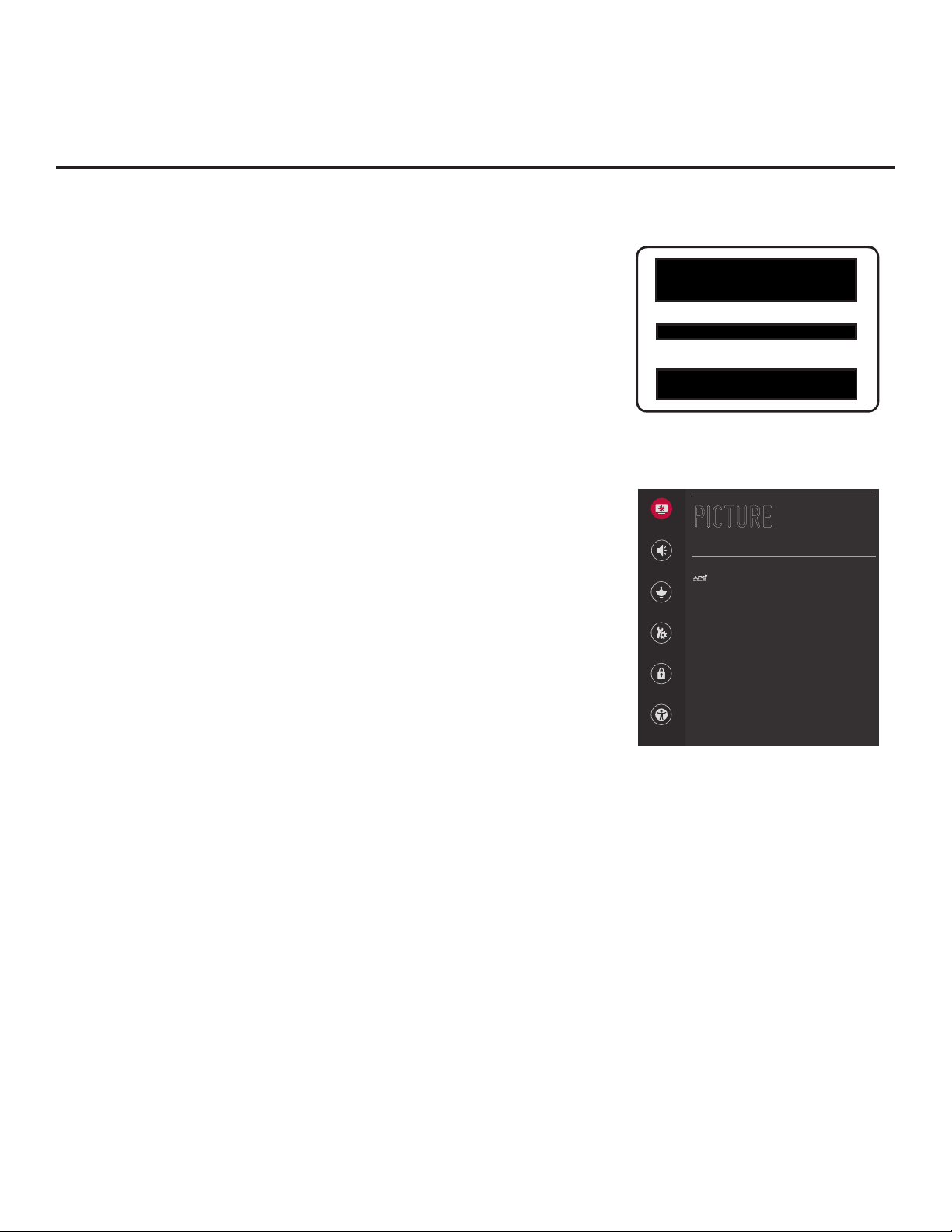
Determining the TV Operating Mode
To determine the operating mode of the TV, press MENU SETTINGS on the Installer Remote. The menu
displayed depends on the operating mode. See examples below.
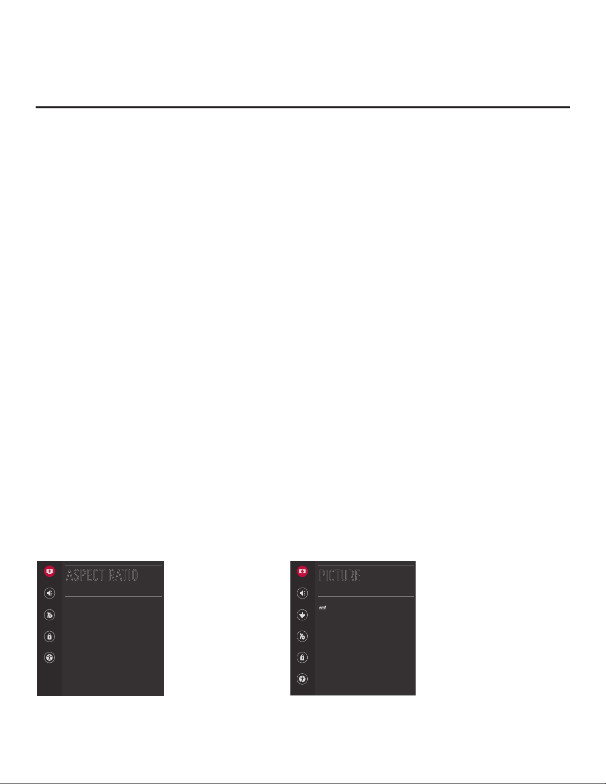
If the Function Menu appears, the TV is in a mode (FTG, PPV, etc.) that does not allow the end user to
change the fundamental TV setup. If the TV setup menus appear, the TV is in Pass-through Mode.
Aspect Ratio
ASPECT RATIO
Sound
Aspect Ratio
16:9
General
Safety
Function Menu
Indicates the TV is not in
Pass-through Mode . While
the TV is in this mode,
Installer Menu settings can
be accessed as read-only.
Picture
Sound
Channels
General
PICTURE
Picture Mode Settings
Aspect Ratio
16:9
Additional Settings
TV Setup Menus
Shows that the TV is in
Pass-through Mode .
Accessibility
206-4340
Safety
Accessibility
9

Pro:Centric Operation
Interactive Menu Features
LG’s Pro:Centric Java (GEM) application enables guests to locate and select television entertainment
using an interactive channel guide, check the daily weather, view hotel and surrounding amenities, etc. via
custom portal interactive menus. The application provides multiple templates for portal interactive menus.
Pro:Centric application features include:
• Portal and information screens/pages (including a “Welcome” page) that include branding logos.
• An optional customized user interface (custom “skins”).
• Billboards and points-of-interest maps that can be customized to focus on hotel amenities, local attractions
and businesses, restaurants, news, events, etc.
• An optional Weather billboard that includes a local radar map, current conditions, and a four day forecast.
• An interactive channel guide that provides a channel list with channel icons. An electronic program
guide (EPG) is an optional feature that displays up to three days of programming information viewable
by channel and time.
• Video spooling that enables the hotel to deliver a video le to guest TVs for promotion and information
purposes.
The Pro:Centric Admin Client web editor/content wizard is provided for customer conguration of portal
content.
Note: Customized content is typically dened by the service integrator and/or hotel administrators. LG
does not provide hotel-specic content.
Interactive Menu Navigation
An LG Pro:Centric-capable TV remote control provides access to both interactive menus and regular TV
features. Press PORTAL on the remote to access the interactive menus.
Example: Pro:Centric Java (GEM) Application Portal
Note: Interactive menu
options may vary,
depending on Pro:Centric
features enabled for the
site. This example shows
typical portal interactive
menus.
10
206-4340

Pro:Centric Operation (Cont.)
Pro:Centric Java Application Setup
The Pro:Centric Java (GEM) application operates in conjunction with FTG and PPV Modes. This section
provides an overview of the setup required for the Pro:Centric features. Administration and management
options for the Pro:Centric server are described in detail in the Pro:Centric Server Admin Client
User Guide. This document describes only those settings that must be specied on the TVs to enable
Pro:Centric remote management and/or the Pro:Centric application.
• Remote management (TV E-Z Installation): The Pro:Centric Admin Client provides remote management
facilities for downloading boot logo image and software updates as well as facilities for downloading a
Clone/Configuration (.tlx) file for FTG Mode via CPU configuration.
• Pro:Centric application: The application comprises the Pro:Centric interactive menus/features described
on the previous page. Pro:Centric application settings are managed via the Pro:Centric Admin Client for
the Java application.
The Pro:Centric remote management facilities and application download are based on Installer Menu
item settings that are used to set up the TV’s Pro:Centric features. The Installer Menu / Pro:Centric server
settings can be congured using one of the methods described below.
TV in Factory Default State
When the TV is in a factory default state, the EZ-Manager Wizard provides automated or manual options
for conguring the TV’s Pro:Centric server settings. See “EZ-Manager Wizard” on pages 12 to 20 for
further information.
The EZ-Manager Wizard also provides a USB conguration option that enables you to congure a TV for
FTG Mode via CPU using a Clone/Configuration (.tlx) le stored on a USB memory device. The “.tlx” le
incorporates FTG Installer Menu settings, including Installer Menu items 098 PRO:CENTRIC and 119 DATA
CHANNEL, which are used to set up the TV’s Pro:Centric feature.
TV in Pass-through Mode
If the EZ-Manager Wizard has been exited and the TV is in Pass-through Mode, either:
• Set Installer Menu items 098 PRO:CENTRIC and 119 DATA CHANNEL to the appropriate values.
See Installer Menu information on pages 25 to 35 for further details. Also, as necessary, refer to
“Custom Master TV Setup” on pages 36 to 38 and/or cloning information on pages 39 to 44.
• Congure the appropriate Pro:Centric server settings in the IP Environment / Pro:Centric Menu. You
must use this option, in particular, if you wish to congure IP settings for the Pro:Centric server. See
“Accessing the IP Environment Menu” on page 51 and “Pro:Centric Setup” on pages 53 to 55 for
further information.
Note: When the TV is in either Pass-through Mode or FTG Mode via CPU, you can also leave Installer
Menu item 119 DATA CHANNEL set to its default value (255) to enable the TV’s Data Channel Auto Search
feature to set the DATA CHANNEL value. See item 119 description on page 34 for additional information.
TV in FTG Mode
If the TV is already in FTG Mode (via CPU or EBL), use the appropriate FTG application to update Installer
Menu items #98 Pro:Centric and #119 Data Channel (along with their afliated elds). Then, transfer the
FTG Installer Menu settings to the TV in accordance with the FTG Mode of conguration. Refer to the
FTG Mode overview on pages 7 to 9 for further information on FTG Mode operation and conguration.
Also—for FTG Mode via CPU only—see note above regarding the option to use the TV’s Data Channel
Auto Search feature to set the DATA CHANNEL value.
206-4340
11

EZ-Manager Wizard
The primary purpose of the EZ-Manager Wizard is to guide you through the process (automated or
manual) of configuring the essential Installer Menu items for Pro:Centric operation. The wizard will
appear on the screen each time the TV is turned ON, until one of its configuration methods has
been completed or the wizard is exited. Use the Installer Remote to make selections and complete
each step.
While the EZ-Manager Wizard is intended primarily for Pro:Centric-related conguration, the
wizard also offers Zoning as well as USB conguration options.
• LT570H TVs support the TV Zoning feature, which enables location-specic congurations (see
Reference section, “Using the TV Zoning Feature,” for further information). The EZ-Manager
Wizard enables you to set the TV Zone # in the TV as part of the conguration process.
• The EZ-Manager Wizard also enables you to access the TV Manager / USB download options
as part of the conguration process, if desired, to perform USB conguration and/or update
functions.
Caution: Do NOT unplug the TV power cord or remove the antenna cable or, if
applicable, the LAN cable during the conguration process, as doing so will interrupt
the current step and may corrupt the conguration data.
Before You Begin
• If you plan to create a customized Master TV Setup using the procedure described on pages 36
to 38, be sure to exit the EZ-Manager Wizard in order to avoid setup conicts or setting modes
that may cause unintended behavior or restrict the custom setup procedure. See also “Initiate
Conguration or Exit the EZ-Manager Wizard” below.
• If it has been completed or exited and therefore does not display, the EZ-Manager Wizard can
be reactivated; however, this requires that you restore the TV to a factory default condition. See
Reference section, “Restoring Factory Defaults on the TV(s),” for further information.
• Each wizard step is allotted a time frame after which the wizard proceeds without user interaction.
If the Pro:Centric server is congured on the system/network and if no location-specic settings
are required in the TV, for example, TV Zone, Label, and/or Room Number settings, you can
simply turn ON the TV, and once initiated, the wizard will proceed through each of the conguration
steps with no further user interaction.
• If any of the conguration steps fails, you will see a “Diagnostics” screen with an indication of the
failure. You will then have the opportunity to reinitiate the conguration process from the previous
screen or exit the EZ-Manager Wizard.
Initiate Conguration or Exit the EZ-Manager Wizard
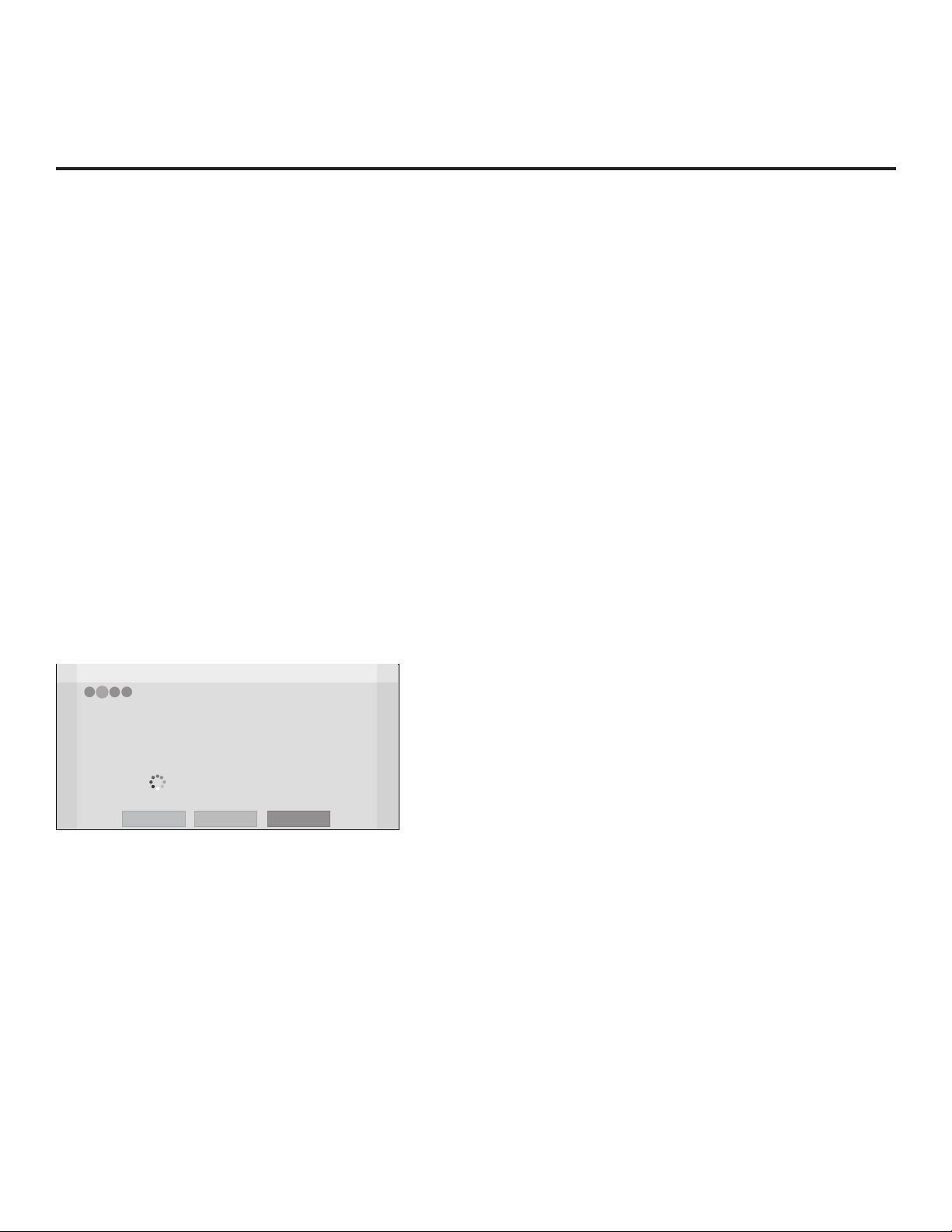
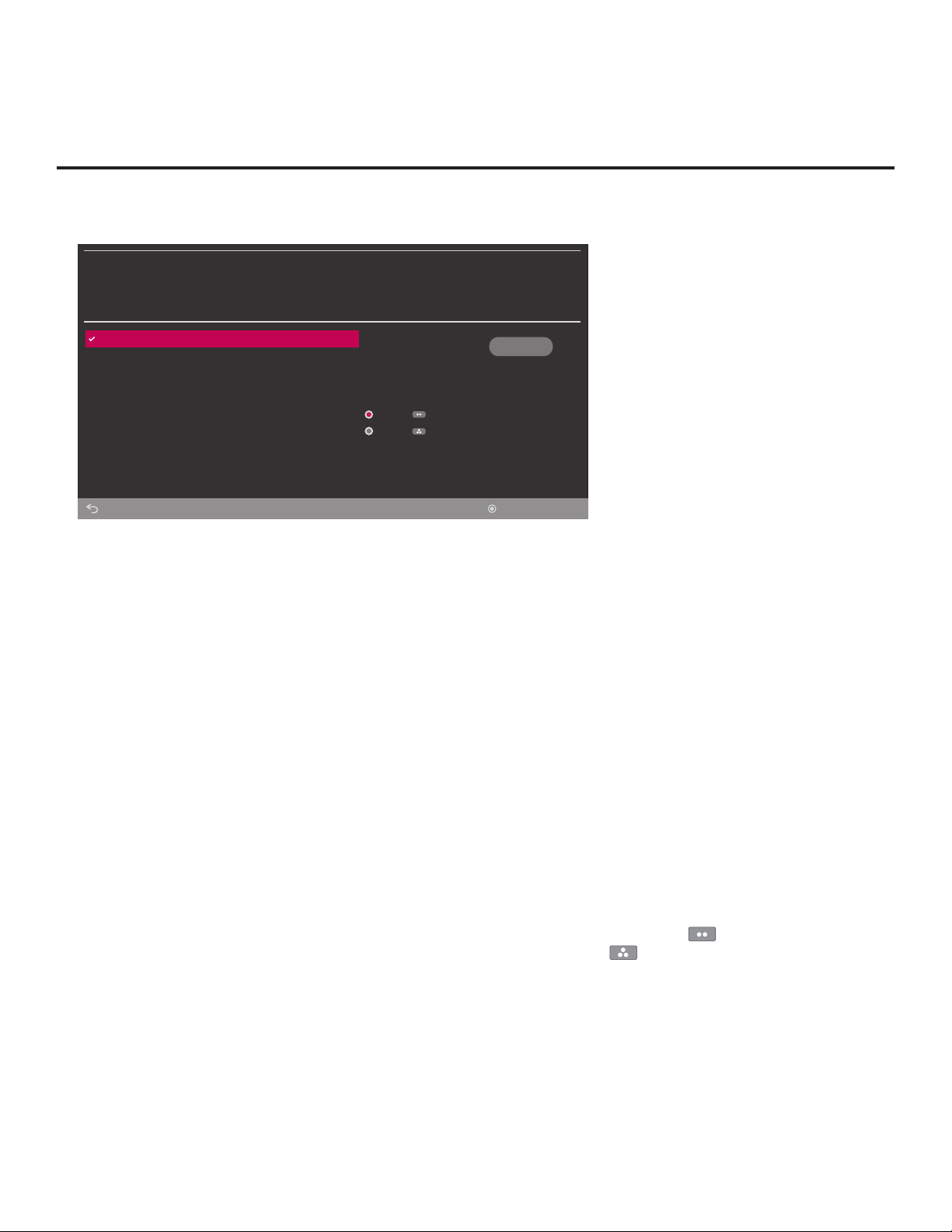
The Welcome screen provides a brief introduction to the EZ-Manager Wizard.
Note: If there is no user action in this screen within 10 seconds, the wizard will proceed to the
rst conguration step. Once the wizard has proceeded, it is not possible to return to the Welcome
screen; however, if you simply wish to exit the wizard, you can do so by selecting the “Exit” option
from the subsequent screen(s).
12
(Continued on next page)
206-4340

(Continued from previous page)
EZ-Manager Wizard
Welcome to LG’s EZ-Manager Wizard
• Use the EZ-Manager Wizard to congure the TV for Pro:Centric operation
or to congure the TV using a USB memory device.
Select ‘Next’ to continue.
• If a Pro:Centric server will not be installed and/or you do not wish to use
the EZ-Manager Wizard to congure this TV, you may exit the wizard.
Select ‘No Pro:Centric’ to disable the Pro:Centric feature of this TV, or
select ‘Exit’ to quit.
This setup wizard will start automatically in 10 seconds.
EZ-Manager Wizard (Cont.)
No Pro:Centric
Exit
Next
Use the arrow keys on the Installer Remote to select the desired option in the Welcome screen:
• To proceed with the EZ-Manager Wizard, select/highlight Next, and then press OK. Then,
continue to the “TV Conguration Options” section below.
• To exit the wizard, but retain the use of the Pro:Centric remote management feature on this TV
(i.e., Installer Menu item 119 DATA CHANNEL set to 255) in the future, select/highlight Exit, and
then press OK. In the conrmation pop-up window, select OK, and then press OK once more on
the Installer Remote.
• If you do not intend to install a Pro:Centric server on this system and you do not wish to use the
wizard’s Zoning or USB conguration options, exit the wizard as follows: Select/highlight No
Pro:Centric, and then press OK. This will disable the Pro:Centric feature of this TV (i.e., Installer
Menu item 119 DATA CHANNEL will be set to 0). In the conrmation pop-up window, select OK,
and then press OK once more on the Installer Remote.
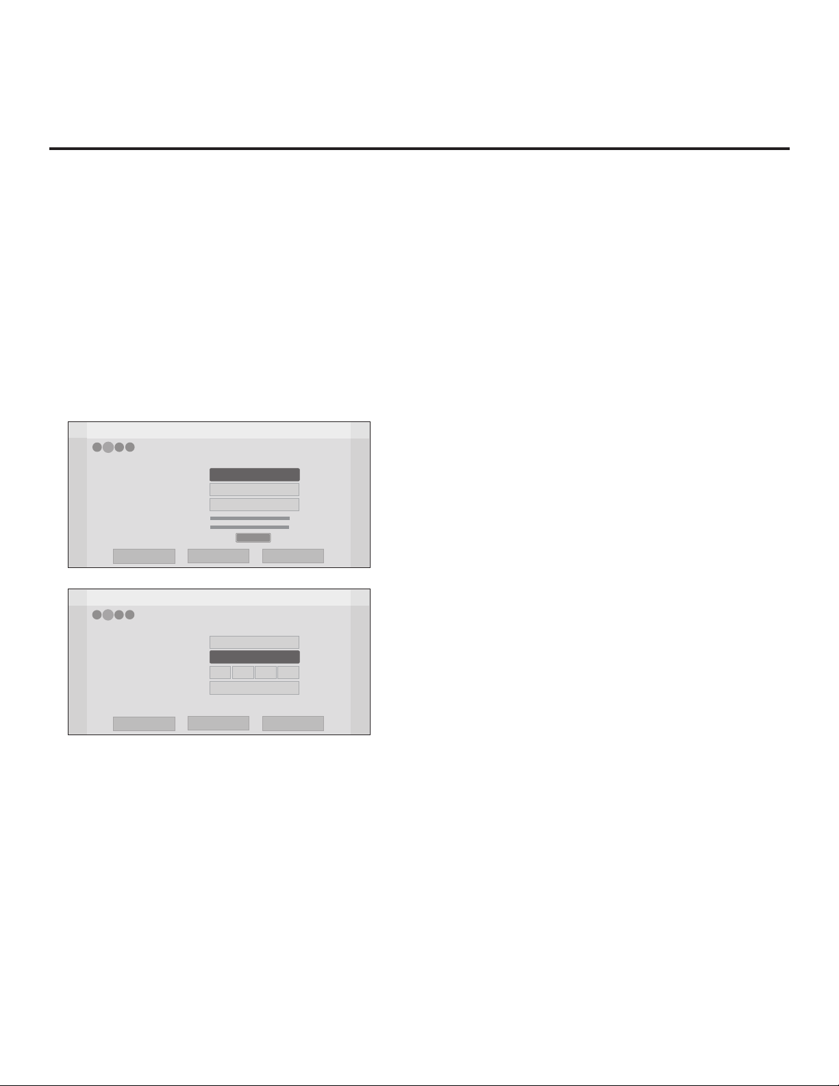
TV Conguration Options
In the TV Conguration Options screen, you can choose how to proceed with the conguration of this
TV (assuming you do not opt to exit the wizard, which you may also do at any time).
Note: If you intend to use the Zoning feature on the TV for location-specic conguration
purposes, select the “Zone & Room Number” option from this screen and set the
appropriate TV Zone # in the TV BEFORE you continue with additional conguration.
Z
EZ-Manager Wizard
4
2
3
1
TV Configuration Options
• To congure the TV for Pro:Centric operation, select ‘Next’.
• To set the optional Zoning feature, select ‘Zone & Room Number’.
• To congure the TV using a USB memory device, select ‘USB Conguration’.
This setup wizard will continue automatically in 60 seconds.
Exit
USB Configuration
Zone & Room Number
Next
Note: If there is no user action in this screen within one minute, the wizard will automatically
continue to the next conguration step.
206-4340
(Continued on next page)
13

EZ-Manager Wizard (Cont.)
CHAR/
(Continued from previous page)
Use the Left/Right arrow keys on the Installer Remote to navigate between options on this screen.
Each time you select/highlight one of the following options, the screen text and elds will change
in accordance with your selection.
• To continue with Pro:Centric conguration, select Next (default) and press OK on the Installer
Remote. See “Congure Pro:Centric Settings” on pages 15 to 18 for additional information.
• To set the Zoning feature on the TV, select Zone & Room Number. See “Zone and Room
Number Assignments” below for further information.
• To access the TV Manager / USB download options, select USB Conguration. See “USB
Conguration” on pages 18 to 20 for further information.
Note: If you choose to exit the EZ-Manager Wizard from this point on, you will have the option to
save any settings made by selecting Save and Exit in the exit conrmation window. Or, you can
exit the wizard without saving any settings by simply selecting OK in the conrmation window.
Zone and Room Number Assignments
You may complete one or more of the elds in the Zone, Label, and Room Number screen or leave
them at their default settings (Zone) or blank (Label and Room Number), as desired. However, if you
intend to use the Zoning feature on this TV, you MUST specify the appropriate value in the Zone
eld as described below. See also Reference section, “Using the TV Zoning Feature,” for further
information.
Note: The TV Zoning feature is only applicable for TVs that will be congured using a “.tlx” le
(local or remote conguration).
Z
EZ-Manager Wizard
4
2
3
1
Zone, Label, and Room Number
•
If creating Zones for Installer Menu settings and/or Channel Mapping, select the appropriate Zone # (0-8)
based on the Zone in which this TV is installed. (See Commercial Mode Setup Guide for more information.)
• Select a Label and/or use the alphanumeric keypad on the remote to input the Room Number.
• When done, select ‘Next’ to continue.
Zone
0
Exit
Label
-----
USB Configuration
Room Number
Zone & Room Number
1
4
7
NUM
2
5 6
8
0
Next
Q.MENU
INPUT
3
TV
DVD
MARK
@
.,;
abc def
1 2 3
ghi jkl mno
4 5 6
pqrs tuv wxyz
7 809
FLASHBK
9
CHAR/NUM
CC
P
A
TIMER
G
CHVOL
E
DELETE
DEL
MUTE
PORTAL
INFO
GUIDE
1. Complete the appropriate eld(s) as described below. Use the Left/Right arrow keys on the
Installer Remote to navigate between each of the elds.
• Zone: Enables you to set a TV Zone # so that the TV can be congured with Installer Menu
and/or Setup Menu settings intended only for the assigned Zone. The Installer Menu and/or
Setup Menu settings may be provided in a Clone/Conguration (.tlx) le. If the TV is being
congured for FTG Mode via CPU, the TV Zone # setting also allows the TV to omit channels
that have been restricted in the FTG Channel Map.
(Continued on next page)
14
206-4340
EZ-Manager Wizard (Cont.)
(Continued from previous page)
To change the TV Zone from its default value (0), navigate to the Zone eld at the left of the
screen, and use the Up/Down arrow keys to specify the desired TV Zone # (1–8).
• Label: Allows you to select a North, South, East, or West text label for this TV. In the Label
eld, use the Up/Down arrow keys to select the applicable label.
• Room Number: Allows you to specify the number of the room—up to 16 characters—in which
the TV is located. In the Room Number eld, you can use the number keys on the Installer
Remote to direct enter a room number. Use the Dash key on the Installer Remote as necessary
to toggle between number and letter characters in the Room Number eld. Also, you can use
the Flashback key on the Installer Remote to delete characters in this eld.
2. When you are ready to continue, select the appropriate option, as follows:
• To proceed to the next EZ-Manager screen, use the arrow keys to select Next, and then press
OK on the Installer Remote. Continue to “Congure Pro:Centric Settings” below.
• To use a USB memory device to complete the conguration, select USB Conguration. See
“USB Conguration” on pages 18 to 20 for further information
Congure Pro:Centric Settings
Once you select “Next” from the TV Conguration Options screen, the Searching for Pro:Centric
Server screen is displayed.
Note: Select the “Back” button, where available, to check previous settings, as necessary.
Z
EZ-Manager Wizard
4
1
3
2
You have the following options:
• You can allow the EZ-Manager Wizard to proceed with a series of automated steps to congure
the TV for Pro:Centric operation and then to look for the Pro:Centric application and maintenance
(E-Z Installation) les to download. In this case, the wizard uses a search algorithm to determine
the Data Channel and the Pro:Centric Application Mode to set in the TV.
Continue with the “Automated Pro:Centric Conguration” subsection below.
• If you already know the settings (e.g., Data Channel and Pro:Centric Application Mode) that need
to be congured in order for the TV to connect to the Pro:Centric server and/or if the Pro:Centric
server is not yet installed, you may expedite the setup process by entering this data manually.
Continue with the “Manual Pro:Centric Conguration” subsection page 17.
Searching for Pro:Centric Server...
It may take 1 min 32 second(s).
This step automatically searches for the Pro:Centric server.
If there is no Pro:Centric Server installed, you do not need to continue
with this procedure. Please select either ‘Exit’ or ‘Manual Pro:Centric’.
Status : Tuning channel 49
TV is now searching all of the channels for the data channel...
Back
Exit
Manual Pro:Centric
206-4340
15

EZ-Manager Wizard (Cont.)
Automated Pro:Centric Conguration
Note: If the server is not yet congured on the system or if Pro:Centric data delivery will be over
IP and there is no Domain Name System (DNS) server, use the manual conguration option to
congure the TV’s Pro:Centric server settings (see “Manual Pro:Centric Conguration” subsection
on page 17). See also note below regarding DNS requirements.
Note: If there is a DNS server at the site, you can create a “procentric.local” DNS entry with the
Pro:Centric server’s IP address. Also, the Pro:Centric server’s port number must be set to “80” to
allow the automated Pro:Centric IP conguration via the EZ-Manager to nd the server.
Once the Pro:Centric data channel is found (a Pro:Centric Server Was Found screen will be
displayed) and the Pro:Centric Application Mode is determined, the wizard will advance to the
Processing the Pro:Centric Conguration screen, which shows the progress of the data downloads
(see example below). Note that some steps may require a few minutes.
If the process is successful, no further user interaction is required, though, in some instances,
where the option (for example “Next”) is available, you may manually move forward to subsequent
steps within the wizard to speed up the process.
EZ-Manager Wizard
4
2
1
3
Processing the Pro:Centric Configuration...
Downloading the maintenance files takes several minutes.
Application files
Maintenance files
– Updating Configuration File
Warning - Do not remove AC power or the signal cables during these steps
Please wait...
Retrieving files from data channel 75
20%
GEM app downloaded
In progress...
Note: If, after completing the search, the TV is unable to nd the Pro:Centric data channel (while the
Searching for Pro:Centric Server screen is on display), the wizard will stop and show a Diagnostics
screen that enables you to manually return to the previous screen (to reinitiate the conguration) or
exit the wizard.
When the Pro:Centric Conguration is complete, an EZ-Manager Conguration Complete screen is
displayed, and after 10 seconds, the wizard exits, and the TV turns OFF.
EZ-Manager Wizard
3
2
1
4
EZ-Manager Configuration Complete
The TV will turn off in 3 second(s).
Installed Components
Pro:Centric Application
Maintenance Files
GEM application downloaded
LT570H_Config.tlx
Reboot
Turn Off
Note: With the EZ-Manager Conguration Complete screen on display, you can also manually turn
off or reboot the TV. If desired, select Turn Off or Reboot, respectively, and then press OK on the
Installer Remote.
16
206-4340
EZ-Manager Wizard (Cont.)
Manual Pro:Centric Conguration
1. With the Searching for Pro:Centric Server screen on display, use the Left/Right arrow keys on
the Installer Remote to select Manual Pro:Centric at the bottom right of the screen, and then
press OK.
In the Pro:Centric Manual Conguration screen (see examples below), you will be able to
congure the appropriate Pro:Centric settings in the TV. Use the Up/Down arrow keys on the
Installer Remote to navigate between elds.
2. In the Pro:Centric Mode eld, use the Left/Right arrow keys to select the appropriate Pro:Centric
Application Mode—GEM (Java) or Conguration Only.
Note: For remote management only, select Conguration Only. The TV will search for TV
E-Z Installation data downloads; however, Pro:Centric application data will not be downloaded,
i.e., Installer Menu item 098 PRO:CENTRIC will be set to 0.
EZ-Manager Wizard
4
3
1
2
Pro:Centric Manual Configuration
Pro:Centric Mode
Media Type
Data Channel
Signal Strength
Signal Quality
Back
Configuration Only
<
Exit
RF
1
No signal
>
Next
Pro:Centric Manual Configuration Screen
with RF Media Fields
Note: By default, the Pro:Centric Manual
0%
0%
Conguration screen initially shows RF
conguration elds.
EZ-Manager Wizard
4
1
3
2
Pro:Centric Manual Configuration
Pro:Centric Mode
Media Type
Address
Port
Back
Configuration Only
IP
< >
255
0
Exit
Pro:Centric Manual Configuration Screen
with IP Media Fields
255255255
Next
3. Refer to the appropriate subsection below, depending on the Pro:Centric server conguration,
to complete the remaining elds.
RF Conguration
a) In the Media Type eld, use the Left/Right arrow keys to select RF.
b) In the Data Channel eld, either key in or use the Left/Right arrow keys to select the RF
channel number that will be used by the Pro:Centric server as its data channel. The Data
Channel value can be set from 1 to 135. *
* PCS150R and later Pro:Centric servers do not support HRC or IRC cable channel frequencies.
(Continued on next page)
206-4340
17

EZ-Manager Wizard (Cont.)
(Continued from previous page)
IP Conguration
a) In the Media Type eld, use the Left/Right arrow keys to select IP.
Note: When you select “IP” as the Media Type, the default (RF) Data Channel and Signal
Strength/Quality elds are replaced with (IP) Address and Port elds.
b) In the Address and Port elds, either key in or use the Left/Right arrow keys to select the
appropriate values for the Pro:Centric server IP address and port number. The IP address
must match the IPv4 multicast address and the port number must match the port number
that is set in the Pro:Centric server.
4. Once all elds are completed as required, you have two options:
• To save the data entered and exit the wizard, use the arrow keys to select Exit and then press
OK. In the subsequent pop-up conrmation window, select Save and Exit, and then press OK
once more. The Pro:Centric application and/or E-Z Installation data will be downloaded to the
TV at a later time. This option is useful, in particular, if the Pro:Centric server has not yet been
congured.
• To initiate a real-time download of Pro:Centric application and/or E-Z Installation data, use the
arrow keys to select Next, and then press OK (see also note below).
Note: With RF conguration, Pro:Centric server data must be present on the RF channel
selected as the TV’s Data Channel in order for you to select “Next” (you will see a “Data
Channel Found” message below the Signal Quality indicator). With IP conguration,
Pro:Centric server data must be present via the wired LAN cable connection in order for
you to select “Next” (you will see a “IP Server Found” message below the Port eld).
If you opt to initiate a real-time download in the last step, the EZ-Manager Wizard will proceed with
the Pro:Centric application and/or E-Z Installation data downloads (see Processing the Pro:Centric
Conguration screen example on page 16). When the Pro:Centric conguration is complete, an
EZ-Manager Conguration Complete screen (see example on page 16) is displayed, and after
10 seconds, the wizard exits, and the TV turns OFF.
Note: With the EZ-Manager Conguration Complete screen on display, you also have the option
to manually turn off or reboot the TV. If desired, select Turn Off or Reboot, respectively, and then
press OK on the Installer Remote.
USB Conguration
TV Manager / USB download options enable you to download conguration, boot logo (splash
screen) image, or software les individually from a USB memory device to the TV. You can also use
the Ez Download utility available from the menu to select multiple types of les to be downloaded
at one time using one process.
Each of the USB download functions requires that you have the appropriate le(s) loaded on a USB
memory device. If you wish to perform a software update or download a boot logo, the software/
image le(s) must be stored in a folder named “LG_DTV” in the root directory of the USB device.
Clone/Conguration (.tlx) les should simply be stored in the root directory of the USB device.
The procedure below assumes that the desired le(s) is/are already loaded onto the USB device.
For further information on TV Manager / USB download options and le requirements, and/or for
information on creating Clone/Conguration (.tlx) les, refer to the appropriate section(s) in this
document.
18
206-4340
EZ-Manager Wizard (Cont.)
Before You Begin
• If you intend to use the Zoning feature on this TV, make sure to set the appropriate TV Zone #
in the EZ-Manager’s Zone, Label, and Room Number screen BEFORE continuing with USB
Conguration. See “TV Conguration Options” on pages 13 to 14 for further information.
• Ensure the USB device to be used has been formatted with FAT format.
• When creating les to be downloaded, avoid using special characters (?, &, @, etc.) in lenames.
• Refer to “Ez Download Utility” on pages 21 to 24 for further information on the Ez Download utility.
• Refer to “Custom Master TV Setup” on pages 36 to 38 for information on creating a Clone (.tlx)
file, and/or refer to “Creating an FTG Conguration File” on pages 45 to 47 for information on
creating an FTG Conguration (.tlx) le for FTG Mode via CPU conguration.
• See Reference section, “Downloading a Boot Logo Image using a USB Memory Device,” for
boot logo image guidelines.
• See Reference section, “Updating TV/PTC Software using a USB Memory Device,” for further
information on software updates.
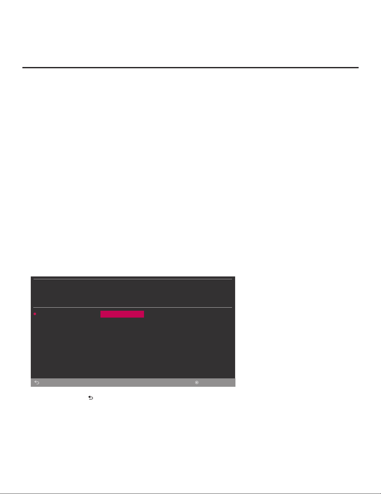
USB Conguration via EZ-Manager Wizard
With either the TV Conguration Options or the Zone, Label, and Room Number screen on display,
proceed as follows to congure the TV using the USB memory device.
1. Insert the USB memory device with the appropriate le(s) into the TV’s USB port.
2. Use the arrow keys on the Installer Remote to select USB Conguration, and then press OK.
You will be redirected to the TV Manager / USB download options.
TV MANAGER
USB
Diagnostics
Back
Note: You can press on the Installer Remote at any time to return to the EZ-Manager Wizard.
Note: Ez Download is always selected by default when you initially access the TV Manager.
Also note that Diagnostics is for service use only.
Ez Download
Download Boot Logo
Update TV Software
Update PTC Software
Import Clone File
OK
206-4340
(Continued on next page)
19

EZ-Manager Wizard (Cont.)
(Continued from previous page)
3. Select the appropriate option from the TV Manager, and initiate the desired download(s).
Update progress will be displayed on the screen. Do NOT remove the USB device while
updates are in progress. When the update process is finished, depending on the type of
update(s) completed, either the EZ-Manager TV Configuration Options screen will be
redisplayed (software and/or boot logo image updates only—see also note below) or the
TV will tune according to the Start Channel setting in the Installer Menu (TV configured with
Clone/Configuration file).
Note: If you are performing a software and/or boot logo image update, the TV will reboot
after the update(s) is/are complete. When the TV Configuration Options screen is redisplayed,
you can either proceed with configuration via the EZ-Manager Wizard or exit the EZ-Manager
Wizard, as required.
4. Remove the USB memory device, and verify that the appropriate configuration/download(s)/
update(s) is/are resident on the TV.
20
206-4340

Ez Download Utility
The Ez Download utility, available from the TV Manager, enables you to select multiple les at one
time from the les loaded on a USB memory device. You may use this utility to download any one
or all of the following to a TV:
• One Clone or FTG Conguration (.tlx) le
• One TV CPU software update
• One PTC software update
• One boot logo (splash screen) image
Before You Begin
• Ensure the USB device has been formatted with FAT format.
• Software update and boot logo image les must be stored in a folder named “LG_DTV” in the
root directory of the USB memory device. Clone/Conguration (.tlx) les should simply be stored
in the root directory of the USB device.
• If the EZ-Manager Wizard appears on the screen when you turn ON the TV, you can use the
wizard’s “USB Conguration” option to access the Ez Download utility (see “TV Conguration
Options” and/or “USB Conguration” on pages 13 and 18, respectively, as necessary).
• If the TV is currently in Pass-through Mode and you intend to use the TV Zoning feature for
location-specic conguration purposes, make sure to set the appropriate TV Zone # in the TV
when directed to do so in the procedure below.
• When creating les to be downloaded, avoid using special characters (?, &, @, etc.) in lenames.
• Refer to “Custom Master TV Setup” on pages 36 to 38 for information on creating a Clone (.tlx)
file, and/or refer to “Creating an FTG Conguration File” on pages 45 to 47 for information on
creating an FTG Conguration (.tlx) le for FTG Mode via CPU conguration.
• See Reference section, “Downloading a Boot Logo Image using a USB Memory Device,” for boot
logo image guidelines.
• See Reference section, “Updating TV/PTC Software using a USB Memory Device,” for further
information on software updates.
Caution: Do not unplug the TV power cord or remove the USB memory device
during a data download, as doing so may cause the TV to malfunction or harm the
USB device, respectively.
Accessing and Using the Ez Download Utility
1. If it is not ON already, turn ON the TV.
2. The next step depends on whether the EZ-Manager Wizard appears on the screen when you
turn ON the TV:
• If the wizard is displayed, you can access the Ez Download utility via the wizard, as indicated
above (see “Before You Begin”). However, to continue with this procedure and access the Ez
Download utility from the TV menus, exit the EZ-Manager Wizard. Then, continue with step 3.
• If the wizard is not displayed, go directly to step 3.
206-4340
(Continued on next page)
21
Ez Download Utility (Cont.)
(Continued from previous page)
3. If the TV is currently in Pass-through Mode, you would like to transfer (import) a “.tlx” le to the
TV via the Ez Download utility, and you intend to use the TV Zoning feature, set the appropriate
TV Zone # in the TV at this time. See Reference section, “Using the TV Zoning Feature,” for
further information.
Note: In order for the proper TV Zone prole data to be applied, the appropriate TV
Zone # must be set in the Target TV BEFORE you continue with the Ez Download
utility.
4. Insert the USB memory device with the appropriate le(s) into the TV’s USB port.
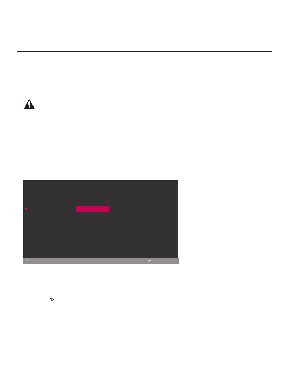
5. To access the TV Manager from the TV menus:
• Press MENU SETTINGS on the Installer Remote to display the TV setup menus (TV is in
Pass-through Mode) or the Function Menu (TV is not in Pass-through Mode).
• Use the arrow navigation keys to select/highlight either the General menu icon from the TV
setup menus or the Safety menu icon from the Function Menu. Then, press the number “7”
key a total of seven times.
Note: Ez Download is always selected by default when you initially access the TV Manager.
Also note that Diagnostics is for service use only.
TV MANAGER
USB
Diagnostics
Back
6. If it is not currently selected, use the arrow keys to select Ez Download, and then press OK.
The Ez Download utility screen (see example below) contains a listing of the TLX (Clone/
Conguration) les stored in the root directory on the USB device and the CPU (EPK), PTC,
and LOGO (boot logo image) les stored in the LG_DTV folder.
Note: Press on the Installer Remote, as necessary, to exit the Ez Download utility and/or
the TV Manager. If you accessed the TV Manager via the EZ-Manager Wizard, you will be
returned to the last screen on display before you selected the “USB Conguration” option. If
you accessed the TV Manager via the TV menus, you will be returned to program viewing.
Ez Download
Download Boot Logo
Update TV Software
Update PTC Software
Import Clone File
OK
22
(Continued on next page)
206-4340
(Continued from previous page)
TV MANAGER
USB
EZ Download
Ez Download Utility (Cont.)
[TLX] ChMap_IM.tlx
[LOGO] BootLogo.jpg
[EPK] CPU_SW.epk
Back
Channel Tuning /
Channel Banner Display
Logical
Physical
Apply
OK
7. To select or de-select a le, respectively, use the Up/Down arrow keys on the Installer Remote to
highlight the lename, and press OK to add or remove the checkmark at the left of the lename.
Note: The utility will only allow you to select one of each le type for downloading. For example,
if there are two TLX les in the Ez Download list, you can only select one or the other of those
two les.
Note: After the Ez Download utility is run, a le is automatically created and stored on the USB
device that was used. The le, which will have a “.dzm” extension, maintains a history of the
le(s) previously used with the Ez Download utility. The next time(s) you use this USB device
with the Ez Download utility, the le(s) selected for the last download will be pre-selected for
the current download, thus facilitating the process of conguring additional TVs of this model
using the same USB device.
8. The elds at the right of the screen will change depending on the currently highlighted le.
Select the appropriate option(s) for each le, as applicable.
• For software and boot logo image les: The elds at the right of the screen show the TV
software versions and any available Forced Update options. Do not select any Forced Update
options unless you have been specically instructed to do so or have previous experience with
Expert Software Updates.
• For Clone/Conguration (.tlx) les: If the selected Clone/Conguration (.tlx) le includes an
FTG Channel Map, a Channel Tuning / Channel Banner Display eld at the right of the screen
enables you to choose the format for the channel tuning/banner display. Press the green
button on the Installer Remote to select Logical tuning, or press the yellow button on
the Installer Remote to select Physical tuning.
Note: If the selected “.tlx” le does not include an FTG Channel Map, the message, “No
Channel Map in Clone le,” will be displayed at the right of the screen.
206-4340
(Continued on next page)
23

Ez Download Utility (Cont.)
(Continued from previous page)
9. When you are ready to continue, use the arrow keys on the Installer Remote to select Apply,
and then press OK.
Update progress will be displayed on the screen. Do NOT remove the USB device while
updates are in progress. When the Ez Download process is complete, an overview of the
results will briey be displayed and then, the TV will either return to program viewing or reboot
(the latter if software and/or the boot logo image has/have just been updated).
10. Remove the USB memory device, and verify that the appropriate configuration/download(s)/
update(s) is/are resident on the TV.
Note for TLX configuration: When configuration is complete, the TV tunes according to the
Start Channel setting in the Installer Menu. If a Start Channel is specied, the TV will tune to that
channel, though in the case of FTG Mode via CPU conguration, a channel banner will only be
displayed if the Start Channel is included in the FTG Channel Map (depending on your selection
in step 8, the channel banner will display either the Start Channel’s logical channel number or
physical RF channel number). Otherwise, the TV will either return to the last channel tuned (TV
in Pass-through Mode) or tune to the rst channel in the FTG Channel Map (TV in FTG Mode via
CPU). In the latter case, remember that the channels in the FTG Channel Map are always
arranged in logical order, regardless of your selection in step 8.
24
206-4340

Use the Installer Menu to set up, change, or view operational settings. This section describes how
to access, use, and exit the Installer Menu from the TV itself. However, you should also refer to the
Installer Menu descriptions in this document if you are conguring the TV CPU using an FTG
Conguration (.tlx) le created using LG’s Cloud Conguration Tool or conguring the EBL locally
(.rml) or remotely (via FMA-LG102 / .fma) using the FTG Device Conguration Application software.
Refer to the table on pages 27 and 28 for brief descriptions of Installer Menu items. More
detailed descriptions follow the table listing.
Accessing the Installer Menu
1. Turn ON the TV.
If the EZ-Manager Wizard appears on the screen when you turn ON the TV, exit the wizard.
2. Using an Installer Remote, press MENU SETTINGS repeatedly until the on-screen display of
the TV setup menus (if the TV is in Pass-through Mode) or the Function Menu (if the TV is not
in Pass-through Mode) no longer toggles, and then press the Installer Menu entry sequence
(e.g., 9-8-7-6) + OK to access the Installer Menu.
Note: The default Installer Menu entry sequence is “9876”; however, if Installer Menu item 000
INSTALLER SEQUENCE has been modied, the entry sequence may be one of three additional
options. See Installer Menu detailed descriptions for further information.
The Installer Menu opens with item 000 INSTALLER SEQ 000.
Installer Menu
PTC INSTALLER MENU
xxLT570H
CPU - CTV
000 INSTALLER SEQ 000
UPN 000-000-000-000 ASIC D279
PTC V#.##.### CPU V#.##.##.##
PTC Version
CPU Version
Typical Installer Menu
The Installer Menu header will vary
depending on the TV you are setting
up. In the Installer Menu footer, you
can see the current software versions
of the TV, as indicated.
Note: If the password (entry sequence) is not entered or registered correctly, you will see the
message “ENTER PASSWORD 0000” at the top of the screen instead of the Installer Menu
header. Once you re-enter the correct password (e.g., press 9-8-7-6 + OK), the Installer Menu will
display.
Note: If the TV is not in Pass-through Mode, the Installer Menu is accessible as read-only. Also,
the TV Zone # will be indicated in the Installer Menu header under the conguration mode indicator
described on the following page.
206-4340
25

Installer Menu (Cont.)
As part of the Installer Menu header (in all modes), two 3-character acronyms are displayed to indicate
the TV’s current conguration mode. The table below lists all possible mode identiers for these TV
models.
Acronym Description
CPU-CTV Pass-through Mode with Channel Lineup in CPU
CPU-FTG FTG Mode via CPU
CPU-P:C Application Tuning Mode via CPU
EBL-FTG FTG Mode via EBL
EBL-LNT SONIFI PPV Mode
MPI-EXT External MPI Control
PTC-CTV Pass-through Mode with Channel Map in PTC
Navigating Within the Installer Menu
Use the Up/Down arrow keys on the Installer Remote to sequence through the available menu items,
or access an item directly by keying in the item number and then pressing MENU SETTINGS. For
example, to access the SLEEP TIMER option, which is item 015, press 0-1-5 + MENU SETTINGS.
Installer Menu items not relevant to these TV models are not present in the Installer Menu; therefore,
some numbers are missing. For example, item 006 will not appear. In addition, items that are
dependent on other Installer Menu item settings will not be initially accessible. For example, item 046
STRT AUX SRCE will not display in the Installer Menu unless item 004 STRT CHANNEL is set to 0.
See Installer Menu detailed descriptions for further information.
Modifying Installer Menu Settings
Refer to the table starting on the next page for an overview of the available Installer Menu items,
including their item numbers, functions, value ranges, and default values.
To change an Installer Menu item value, use the Left/Right arrow keys on the Installer Remote to
select the appropriate value, or direct enter a valid value. To save the new setting, press OK once
on the Installer Remote. If you have additional items to modify, use the Up/Down arrow keys to
navigate to a new Installer Menu item or access an item directly as described in the previous section.
Note that invalid values will not be saved.
Caution: In order for Installer Menu item changes to be saved, you must press OK as
indicated above and then exit the Installer Menu as described below. Never remove
power from the TV while in the Installer Menu. Also, remember that Installer Menu
settings may affect options available from the TV setup menus or the Function Menu.
Exiting the Installer Menu and Activating Settings
After you have adjusted all required Installer Menu item settings, press OK once on the Installer
Remote to save your changes; then, press OK again to exit the Installer Menu. Any changes you
make will be stored in non-volatile memory.
Note: Each time you exit the Installer Menu in Pass-through Mode, all V-Chip (Parental Control)
settings in the TV are reset to their default values; that is, the Lock System, if previously enabled from
the Safety Menu, will now be disabled, and the individual Parental Control settings will be restored
to default values.
26
206-4340

Installer Menu (Cont.)
Installer Menu Items 000 through 071
Item Function Value Range Default Value Brief Description of Function
000 INSTALLER SEQ 0 – 3 0 Leave default set to 0.
001 POWER MANAGE 0 – 7 0
002 AC ON 0 – 3, 16 – 19 0
003 BAND/AFC 0 – 3 1 Selects the RF Tuning Band: 0=Broadcast, 1=Cable, 2=HRC, 3=IRC
004 STRT CHANNEL 0 – 127, 255 255
005 CHAN LOCK 0 / 1 0 If set to 1, cannot tune from current channel.
007 STRT VOLUME 0 – 63, 255 255
008 MIN VOLUME 0 – 63 0 Sets the minimum allowable volume setting.
009 MAX VOLUME 0 – 63 63 Sets the maximum allowable volume setting.
010 MUTE DISABLE 0 / 1 0 Set to 1 to disable the Mute function.
015 SLEEP TIMER 0 / 1 1 Set to 1 to enable the Sleep Timer feature.
016 EN. TIMER 0 / 1 0 Set to 1 to enable On/Off timers.
017 ALARM 0 / 1 1 Set to 1 to enable the Alarm feature in the Function Menu.
020 FEATURE LEVEL 0, 16 – 24 0 Determines an additional IR code scheme to which the TV will respond.
021 V-CHIP 0 / 1 1 Set to 1 to enable V-Chip (Parental Control) functions.
022 MAX BLK HRS 0 – 99 12
023 CAPTION LOCK 0 / 1 0 Set to 1 to retain the caption setting selected before the TV was turned OFF.
028 CH. OVERIDE 0 / 1 1
029 REMAP AUX INPS 0 / 1 0 Set to 1 to remap the PTC’s direct tune channels for Aux inputs from 13x to 9x.
030 ACK MASK 0 / 1 0 If set to 1, enables the ACK feature of MPI.
031 POLL RATE 20 – 169 94 Selects the poll rate for MPI.
032 TIMING PULSE 186 – 227 207 Sets the baud rate for MPI.
035 HDMI1 ENABLE 0 – 2 1
039 REAR AUX EN. 0 / 1 1 Set to 1 to enable the display panel AV input jack.
041 SIMPLINK EN 0 – 3 0 Determines the status of the SIMPLINK feature. See detailed descriptions.
042 AUTO INPUTS 0 – 255 0
046 STRT AUX SRCE 1, 3, 5, 7, 255 7 Sets the starting Aux source (if item 004 STRT CHANNEL is set to 0).
047 AUX STATUS 0 / 1 0
053 DIS. CH-TIME 0 / 1 0 Set to 1 to disable the TV’s native Channel-Time display.
069 EN. CH-T COL. 0 / 1 1 Set to 1 to enable custom color for MPI display characters.
070 FOR. CH-TIME 0 – 7 2 Chooses custom foreground color for MPI display characters.
071 BCK. CH-TIME 0 – 7 2 Chooses custom background color for MPI display characters.
Selects the number of hours of inactivity allowed before the TV automatically
turns itself OFF. Set to 0 to disable Power Management.
Determines the status of the TV (ON, Instant ON enabled, etc.) when AC power
is applied. See detailed descriptions.
Channel tuned when the TV is turned ON. (Set to 255 to tune to channel
tuned before the TV was turned OFF.)
Volume level when the TV is turned ON. (Set to 255 to use volume level set
before the TV was turned OFF.)
Determines the maximum number of Parental Control blocking hours that can
be set in the Function Menu.
If set to 0, users can only tune to channels that are included in the PTC
Channel Map. See detailed descriptions.
Set to 0 to disable HDMI 1. Set to 1 (DTV Mode) or 2 (PC Mode), as
applicable, to enable HDMI 1.
Determines the Aux inputs for which auto-sensing is enabled. See detailed
descriptions.
Controls the MPI status channel response for Aux sources. Set to 1 for Aux
source to be reported as its channel number.
206-4340
27
 Loading...