

Page 1

Test Report No.: GETEC-E3-06-041
FCC Class B Certification
APPENDIX H
: USER’S MANUAL
EUT Type: 32” LCD Monitor
FCC ID: BEJ32LRJ
Page 2

Retain it for future reference.
Record model number and serial number of the set.
See the label attached on the back cover and quote
this information to your dealer when you require service.
P/NO : 38289U0577F (0605-REV00)
Printed in Korea
LCD TV
PLASMA TV
OWNER’S MANUAL
LCD TV MODELS
26LC2R
*
32LC2R
*
PLASMA TV MODELS
42PC3RV
*
577Fen_cover 06/5/4 9:36 AM Page 1
Page 3
WARNING
1
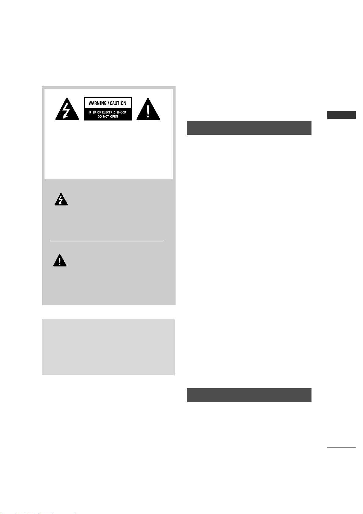
WARNING / CAUTION
WARNING / CAUTION
To prevent fire or shock hazards, do not expose
this product to rain or moisture.
FCC NOTICE
Class B digital device
This equipment has been tested and found to comply with the limits for a Class B digital device, pursuant to Part 15 of the FCC Rules. These limits are
designed to provide reasonable protection against
harmful interference in a residential installation. This
equipment generates, uses and can radiate radio frequency energy and, if not installed and used in
accordance with the instructions, may cause harmful
interference to radio communications. However,
there is no guarantee that interference will not
occur in a particular installation. If this equipment
does cause harmful interference to radio or television reception, which can be determined by turning
the equipment off and on, the user is encouraged to
try to correct the interference by one or more of
the following measures:
- Reorient or relocate the receiving antenna.
- Increase the separation between the equipment
and receiver.
- Connect the equipment to an outlet on a circuit
different from that to which the receiver is connected.
- Consult the dealer or an experienced radio/TV
technician for help.
Any changes or modifications not expressly
approved by the party responsible for compliance
could void the user’s authority to operate the
equipment.
CAUTION
Do not attempt to modify this product in any way
without written authorization from LG Electronics.
Unauthorized modification could void the user’s
authority to operate this product
The lightning flash with arrowhead
symbol, within an equilateral triangle,
is intended to alert the user to the
presence of uninsulated “dangerous voltage”
within the product’s enclosure that may be of
sufficient magnitude to constitute a risk of electric
shock to persons.
The exclamation point within an equilateral
triangle is intended to alert the user to
the presence of important operating and maintenance (servicing) instructions in the literature
accompanying the appliance.
TO REDUCE THE RISK OF ELECTRIC SHOCK
DO NOT REMOVE COVER (OR BACK). NO
USER SERVICEABLE PARTS INSIDE. REFER TO
QUALIFIED SERVICE PERSONNEL.
WARNING/CAUTION
TO REDUCE THE RISK OF FIRE AND ELECTRIC
SHOCK, DO NOT EXPOSE THIS PRODUCT TO
RAIN OR MOISTURE.
Page 4
WARNING
2
WARNING
IMPORTANT SAFETY INSTRUCTIONS
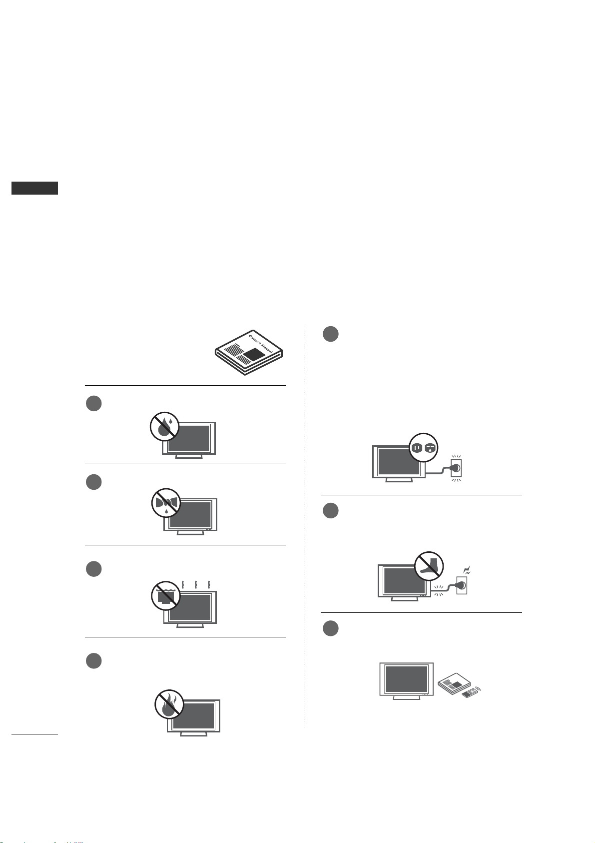
Read these instructions.
Keep these instructions.
Heed all warnings.
Follow all instructions.
Do not use this apparatus near water
Clean only with dry cloth.
Do not block any ventilation openings. Install in
accordance with the manufacturer’s instructions.
Do not install near any heat sources such as
radiators, heat registers, stoves, or other apparatus
(including amplifiers)that produce heat.
Do not defeat the safety purpose of the
polarized or grounding-type plug. A polarized
plug has two blades with one wider than the
other. A grounding type plug has two blades
and a third grounding prong, The wide blade
or the third prong are provided for your safety.
If the provided plug does not fit into your
outlet, consult an electrician for replacement
of the obsolete outlet.
Protect the power cord from being walked on
or pinched particularly at plugs, convenience
receptacles, and the point where they exit
from the apparatus.
Only use attachments/accessories specified
by the manufacturer.
Important safety instructions shall be provided with each apparatus. This information shall be given in a separate
booklet or sheet, or be located before any operating instructions in an instruction for installation for use and
supplied with the apparatus.
This information shall be given in a language acceptable to the country where the apparatus is intended to
be used.
The important safety instructions shall be entitled “Important Safety Instructions”. The following safety
instructions shall be included where applicable, and, when used, shall be verbatim as follows. Additional safety
information may be included by adding statements after the end of the following safety instruction list. At
the manufacturer’s option, a picture or drawing that illustrates the intent of a specific safety instruction may
be placed immediately adjacent to that safety instruction :
Owner ManualOwnerManual
1
2
3
4
5
6
7
Page 5
WARNING
3
WARNING
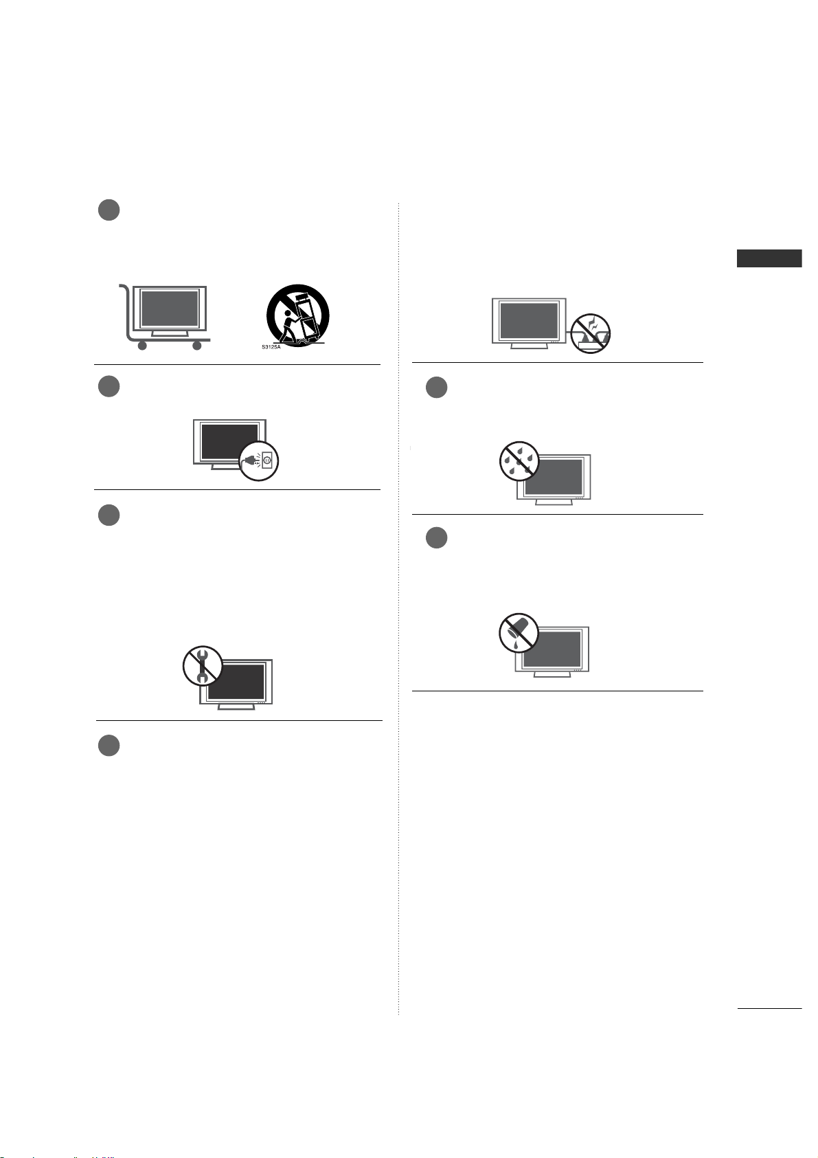
Use only with the cart, stand, tripod, bracket,
or table specified by the manufacturer, or sold
with the apparatus. When a cart is used, use
caution when moving the cart/apparatus
combination to avoid injury from tip-over.
Unplug this apparatus during lightning storms
or when unused for long periods of time.
Refer all servicing to qualified service personnel. Servicing is required when the apparatus
has been damaged in any way, such as powersupply cord or plug is damaged, liquid has
been spilled or objects have fallen into the
apparatus, the apparatus has exposed to rain
or moisture, does not operate normally, or
has been dropped.
CAUTION concerning the Power Cord :
Most appliances recommend they be placed
upon a dedicated circuit; that is, a single outlet
circuit which powers only that appliance and
has no additional outlets or branch circuits.
Check the specification page of this owner's
manual to be certain.
Do not overload wall outlets. Overloaded wall
outlets, loose or damaged wall outlets, extension
cords, frayed power cords, or damaged or
cracked wire insulation are dangerous. Any of
these conditions could result in electric shock
or fire. Periodically examine the cord of your
appliance, and if its appearance indicates
damage or deterioration, unplug it, discontinue
use of the appliance, and have the cord
replaced with an exact replacement part by
an authorized servicer. Protect the power
cord from physical or mechanical abuse, such
as being twisted, kinked, pinched, closed in a
door, or walked upon. Pay particular attention
to plugs, wall outlets, and the point where
the cord exits the appliance.
Outdoor Use Marking :
WARNING - To Reduce The Risk Of Fire Or
Electric Shock, Do Not Expose This Appliance
To Rain Or Moisture
Wet Location Marking : Apparatus shall not
be exposed to dripping or splashing and no
objects filled with liquids, such as vases, shall
be placed on or over apparatus.
8
9
10
11
12
13
Page 6

6
INTRODUCTION
INTRODUCTION
What is a Plasma TV ?
Using plasma is the best way to achieve flat panel
displays with excellent image quality and large
screen sizes that are easily viewable. The Plasma TV
can be thought of as a descendant of the neon
lamp and or a series of fluorescent lamps.
How does it work?
Plasma TV is an array of cells, known as pixels, which
are comprised of three sub-pixels, corresponding to
the colors red, green, and blue. Gas in a plasma
state is used to react with phosphors in each subpixel to produce colored light (red, green, or blue).
These phosphors are the same types used in
Cathode Ray Tube (CRT) devices such as televisions
and common computer monitors.
Plasma TV offers a rich, dynamic display because
each sub-pixel is individually controlled by advanced
electronics to produce over 16 million different colors. This means that you get perfect images that are
easily viewable in a display that is fewer than five
inches thick.
160° - Wide angle range of vision
Your flat panel plasma screen offers an exceptionally
broad viewing angle of over 160 degrees. This
means that the display is clear and visible to viewers
anywhere in the room.
Wide Screen
The wide screen offers a theater-like experience in
your own home.
Multimedia
Connect your plasma display to a PC and use it for
conferencing, games, and Internet browsing. The
Picture-in-Picture feature allows you to view your PC
and video images simultaneously.
Versatile
The light weight and thin size makes it easy to
install your plasma display in a variety of locations
where conventional TVs do not fit.
The Plasma TV Manufacturing Process: a few
minute colored dots may be present on the
Plasma TV screen
The Plasma TV is composed of 0.9 to 2.2 million
cells. A few cell defects will normally occur in the
Plasma TV manufacturing process. Several tiny,
minute colored dots visible on the screen should be
acceptable. This also occurs in other Plasma TV
manufacturers' products. The tiny dots appearing
does not mean that this Plasma TV is defective.
Thus a few cell defects are not sufficient cause for
the Plasma TV to be exchanged or returned. Our
production technology minimizes these cell defects
during the manufacture and operation of this product.
FOR LCD TV
If the TV feels cold to the touch, there may be a
small “flicker” when it is turned on. This is normal,
there is nothing wrong with TV.
Some minute dot defects may be visible on the
screen, appearing as tiny red, green, or blue spots.
However, they have no adverse effect on the monitor's performance.
Avoid touching the LCD screen or holding your finger(s)
against it for long periods of time. Doing so may produce some temporary distortion effects on the screen.
On DDisposal
a. The fluorescent lamp used in this product con-
tains a small amount of mercury.
b. Do not dispose of this product with general
household waste.
c. Disposal of this product must be carried out in
accordance to the regulations of your local
authority.
Page 7

7
ACCESSORIES
INTRODUCTION
Ensure that the following accessories are included with your product. If an accessory is missing, please contact the dealer where you purchased the product.
Owner's Manual
1.5V 1.5V
Owner’s Manual Batteries
ENTER
INPUT
TVTV
INPUT
PIP CH- PIP CH+
PIP INPUT
DVD
ARC
EXIT
VOL
REVIEW
MUTE
CH
SLEEP
MEMORY/ERASE
MENU
CAPTION
PIP SIZE
POSTION
VCR
POWER
123
456
789
*
0
FCR
MTS
Remote Control Power Cord
For 442PC3RV*
For 226LC2R*/32LC2R*
2-TV Bracket Bolts 4-Bolts for stand assembly
(Refer to p.15)
Cable Management
(Refer to p.19)
Twister Holder
Arrange the wires
with the twister holder.
2-TV Brackets,
2-Wall Brackets
2- Bolts for stand assembly
(Refer to p.14)
2-Wall brackets
2-eye-bolts
Polishing Cloth
Polish the screen
with the cloth.
32LC2R* only
Page 8

8
INTRODUCTION
CONTROLS
INTRODUCTION
This is the front panel of models 42PC3RV* TVs.
■
This is a simplified representation of the front panel.
■
Here shown may be somewhat different from your TV.
Front Panel Controls
VOL
MENU
INPUT
Remote Control Sensor
Power Standby Indicator
Illuminates red in standby mode.
Illuminates white when the set is switched on.
CHANNEL Buttons
VOLUME Buttons
ENTER Button
MENU Button
INPUT Button
ON/OFF Button
CH
VOL
ENTER
MENU
INPUT
Page 9
9
INTRODUCTION
CONNECTION OPTION
REMOTE
CONTROL IN
AUDIO IN
(RGB/DVI)
AC IN
MONO
( )
AUDIO
RGB IN
(PC/DTV)
RS-232C IN
(CONTROL&SERVICE)
HDMI IN
ANTENNA
IN
VIDEO
S-VIDEO
AUDIO OUT
VARIABLE
VIDEO
AUDIO
COMPONENT IN
AV IN 2
L/MONO
R
AUDIOAUDIO
VIDEOVIDEO
1
2
AV IN 1
AV OUT
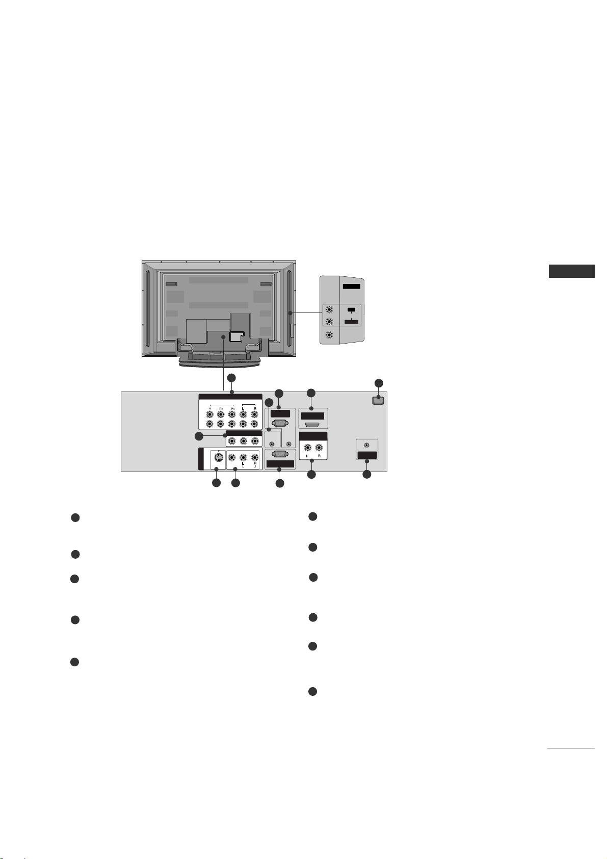
This manual explains the features available on the 42PC3RV*.
Back Connection Panel
AUDIO Input
Connections are available for listening to stereo sound from an external
device.
VIDEO Input
Connects the video signal from a
video device.
COMPONENT IN
Connect a component video/audio device to
these jacks.
Remote Control Port
Connect your wired remote control.
RGB/AUDIO IN
Connect the output from a settop box or PC to
the appropriate input port
HDMI IN
Connect a HDMI signal to HDMI port with HDMI
cable.
Power Cord Socket
For operation with AC power.
Caution:
Never attempt to operate the TV on DC power.
AV OUT
Connect a second TV or monitor.
S-VIDEO
Connect S-Video out from an S-VIDEO device.
AV (Audio/Video) IN 1
Connect audio/video output from an external
device to these jacks.
RS-232C IN (CONTROL & SERVICE) PORT
Connect to the RS-232C port on a PC.
Variable Audio Output
Connect an external amplifier or add a subwoofer
to your surround sound system.
ANTENNA IN
Connect over-the air signals to this jack.
1
2
3
4
7
6
5
8
9
10
11
6
7
8
1
3
2
9
4
10
11
5
Page 10

10
INTRODUCTION
INTRODUCTION
This is the front panel of models 26/32LC2R* TVs.
■
This is a simplified representation of the front panel. Here shown may be somewhat different from your TV.
Front Panel Controls
VOL
MENU
INPUT
Remote Control Sensor
Power Standby Indicator
Illuminates red in standby mode.
Illuminates white when the set is switched on.
CHANNEL Buttons
VOLUME Buttons
ENTER Button
MENU Button
INPUT Button
ON/OFF Button
CONTROLS
CH
VOL
ENTER
R
MENU
INPUT
Page 11
11
CONNECTION OPTIONS
INTRODUCTION
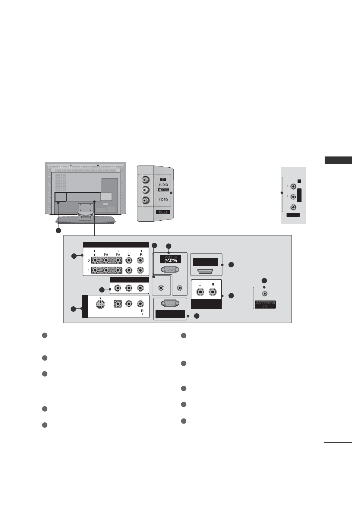
This manual explains the features available on the 26/32C2R*.
VIDEO
AV IN 2
L/MONO R
/
MONO
AUDIO
REMOTE
CONTROL IN
AUDIO IN
(RGB)
MONO
( )
AUDIO
RGB IN
RS-232C INRS-232C IN
(CONTROL(CONTROL& SERVICE)SERVICE)
HDM INHDM IN
VIDEOVIDEO
S-VIDEOS-VIDEO
AV IN 1AV IN 1
AUDIO OUTAUDIO OUT
VARIABLE
VIDEO
AUDIO
COMPONENT INCOMPONENT IN
AV OUTAV OUT
Back Connection Panel
AUDIO Input
Connections are available for listening stereo
sound from an external device.
VIDEO Input
Connects the video signal from a video
device.
COMPONENT IN
Connect a component video/audio device to
these jacks.
AV OUT
Connect a second TV or monitor.
AV (Audio/Video) IN 1
Connect audio/video output from an externa
device to these jacks.
S-VIDEO
Connect S-Video out from an S-VIDEO device.
Remote Control Port
Connect your wired remote control.
RGB/AUDIO IN
Connect the output from a settop box or PC to
the appropriate input port.
HDMI IN
Connect a HDMI signal.
Or DVI(VIDEO)signal to the this port with a DVI
to HDMI cable.
VARIABLE AUDIO OUT
Connect an external amplifier or add a subwoofer
to your surround sound system.
RS-232C IN (CONTROL &SERVICE) PORT
Connect to the RS-232C port on a PC.
ANTENNA IN
Connect over-the air signals to this jack.
Power Cord Socket
For operation with AC power.
Caution: Never attempt to operate the TV on DC
power.
1
2
3
1
7
6
8
9
10
2
3
4
5
5
9
4
6
7
8
10
32LC2R 26LC2R
Page 12
INTRODUCTION
12
INTRODUCTION
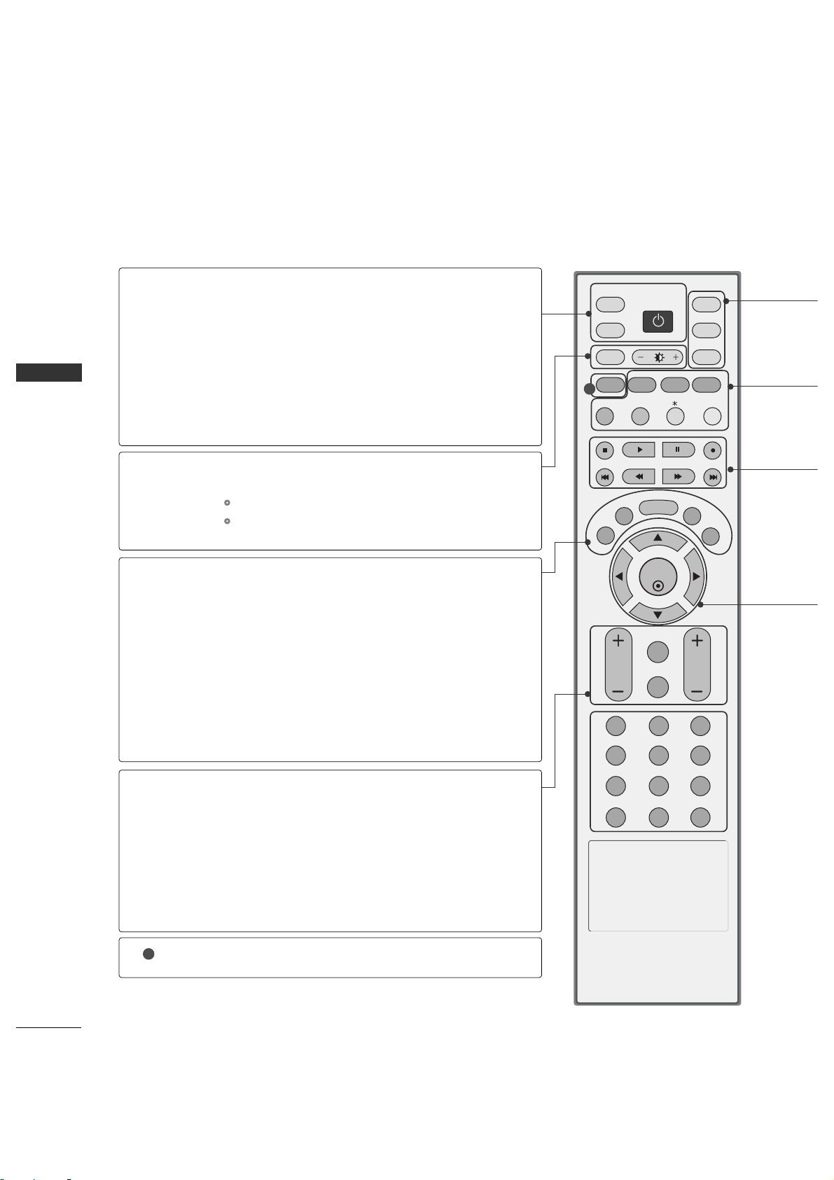
REMOTE CONTROL KEY FUNCTIONS
When using the remote control, aim it at the remote control sensor on the TV.
ENTER
INPUT
TVTV
INPUT
PIP CH- PIP CH+
PIP INPUT
DVD
ARC
EXIT
VOL
REVIEW
MUTE
CH
SLEEP
MEMORY/ERASE
MENU
CAPTION
PIP SIZE
POSTION
VCR
POWER
123
456
789
*
0
MTS
FCR
POWER
TV INPUT
INPUT
ARC
Brightness
adjustment
EXIT
MEMORY/ERASE
MENU
MTS
SLEEP
VOLUME UP
/DOWN
REVIEW
MUTE
CHANNEL
UP/DOWN
CAPTION
Turns your TV or any other programmed equipment on
or off, depending on mode.
Returns to the TV mode.
If you press the button once, the input source OSD will
appear on screen as shown. Press the
DD/E
button and
then ENTER button to select the desired input source
(TV, AV1, AV2, Component 1, Component 2, RGB, or
HDMI).
Change the aspect ratio.
G
p.70
Adjusts brightness on screen.
It returns to the default settings brightness by changing
mode source.
Clears all on-screen displays and returns to TV viewing
from any menu.
Memorizes or erases selected channel.
G
p.35
Displays the main menu.
Selects the MTS sound:
Mono, Stereo
, or
SAP
.
G
p.51
Select the amount of time before your TV turns off automatically.
G
p.56
Increases/decreases the sound level.
Tune to the last channel viewed.
Switches the sound on or off.
Select available channels.
Selects CAPTION mode.
G
p.60
1
1
Page 13
13
INTRODUCTION
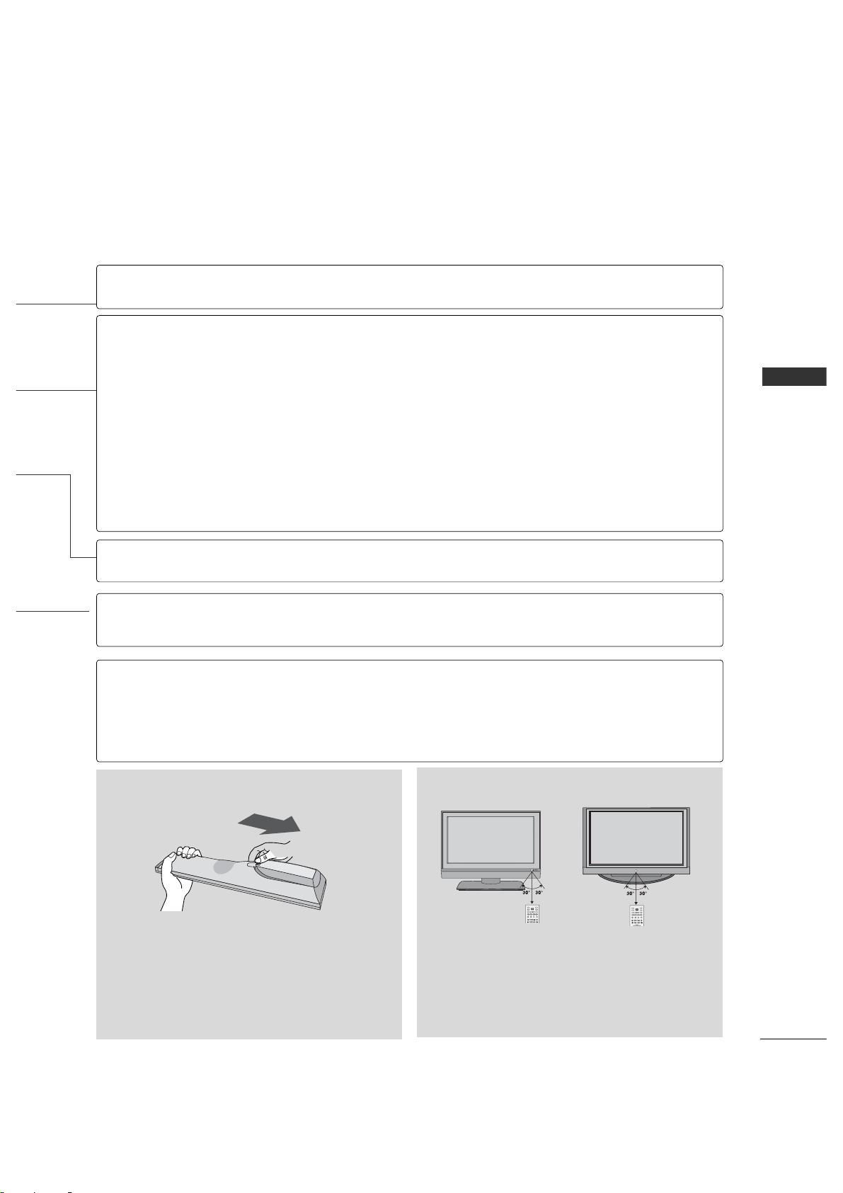
■
Open the battery compartment cover on the back
side and install the batteries matching correct
polarity (+with +,-with -).
■
Install two 1.5V AA batteries. Don’t mix old or
used batteries with new ones.
■
Close cover.
■
Use a remote control up to 7 meters distance and
30 degree (left/right) within the receiving unit
scope.
■
Dispose of used batteries in a recycle bin to
preserve environment.
TVD/A
INPUT
INPUT
DVD
ARC
LIST
I/II
MENU
TEXT PIP
GUIDE
INFO
VCR
POWER
TVD/A
INPUT
INPUT
DVD
ARC
TEXT PIP
GUIDE
INFO
VCR
POWER
Installing Batteries Remote control effective range
MODE
PIP
SIZE
POSITION
PIP CH - /+
PIP INPUT
THUMBSTICK
(Up/Down/Left
/Right/ENTER)
FCR
Selects the remote operating mode: TV, VCR, DVD.
Switches the sub picture PIP, DW mode.
G
p.31
Adjusts the sub picture size.
G
p.32
Moves the sub picture.
G
p.32
Selects a channel for the sub picture.
G
p.31
Not functional
Select the connected input source for the sub-picture.
G
p.31
Control video cassette recorders or DVD players.
Navigate the on-screen menus and adjust the system settings to your preference.
Not functional
Scroll through the programmed Favorite channels.
NUMBER button
VCR/DVD
control buttons
*
*
R
Page 14
INSTALLATION
14
UNFOLDING THE STAND BASE
INSTALLATION
NOTE
!
(B)
(A)
(D)
(C)
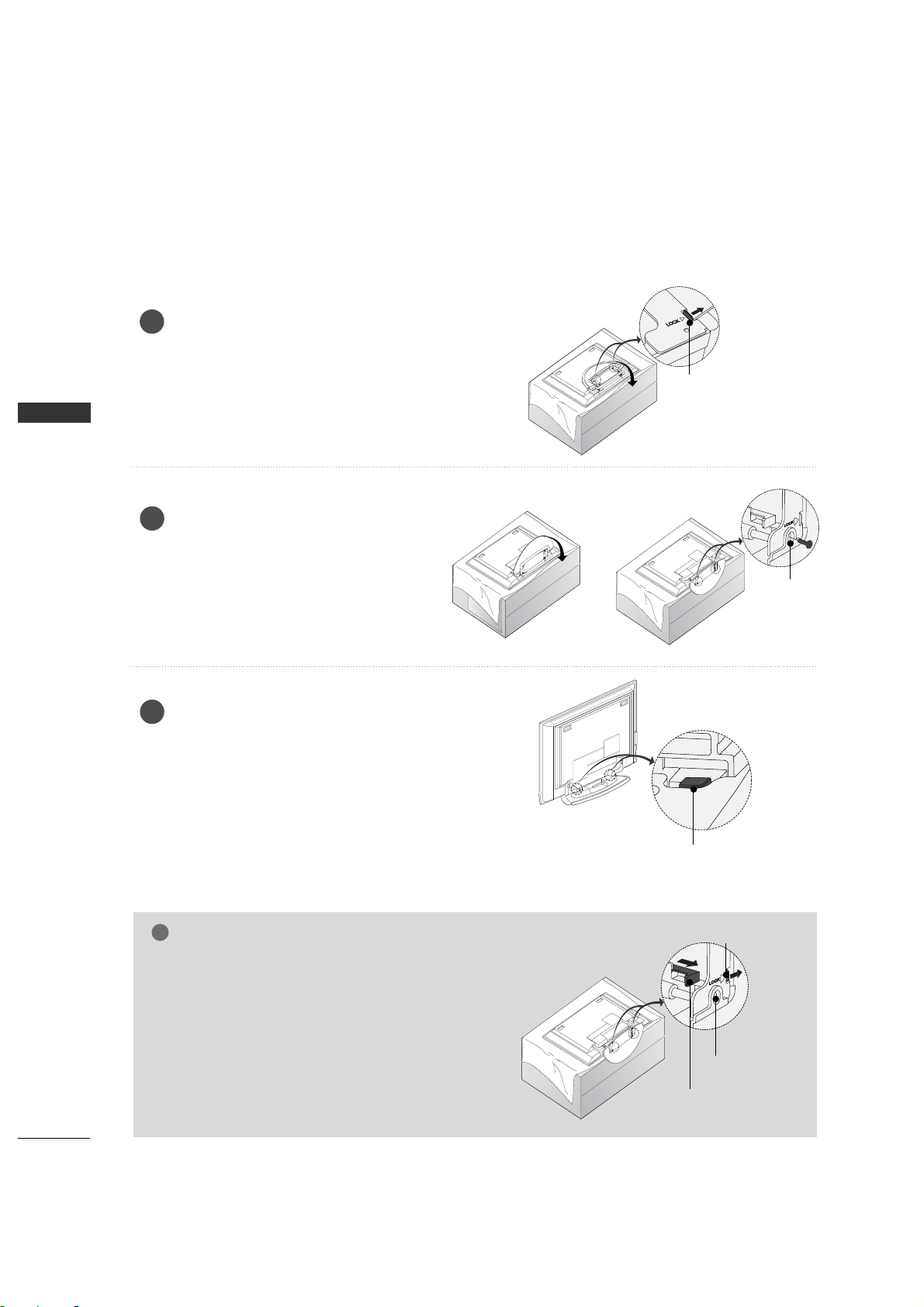
Place the set with the screen facing
down on a cushion or soft cloth as
shown.
Before unfolding the stand, please make
sure two locks (A) on the bottom of the
stand push outward.
Pull the stand out as shown.
After unfolding the stand, please insert
and tighten the screws (provided as
parts of the product) in the holes (B) on
the bottom of the stand.
1
2
When connecting cables to the set, Do
not disengage the lock (C).
This may cause the set to fall, causing
serious bodily injury and serious damage
to the set.
3
(A)
(B)
G
When cclosing tthe sstand ffor ss t ora g e
■
First remove the screws in the holes (B) on the
bottom of the stand. And then pull two Hooks
(D) of the stand bottom and fold the stand into
the back of the set.
■
After folding, push the two Locks (A) of the
stand bottom outward.
Image shown here may be slightly different from your set.
Page 15
INSTALLATION
15
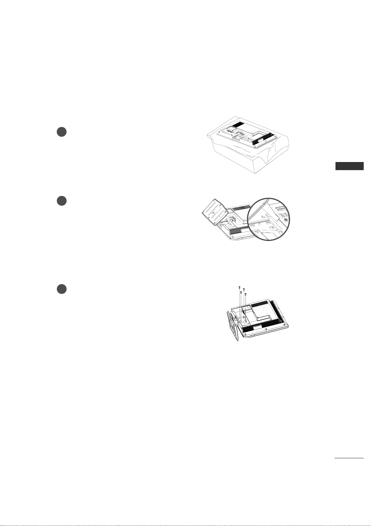
STAND INSTALLATION
(For 32LC2R*)
INSTALLATION
Carefully place the product screen
side down on a cushioned surface that
will protect product and screen from
damage.
Place the product stand on the product
as shown.
Install the 4 bolts securely, in the back
of the product in the holes provided.
1
2
3
Page 16
16
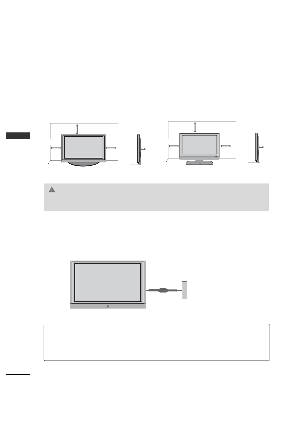
DESKTOP PEDESTAL INSTALLATION
INSTALLATION
INSTALLATION
For proper ventilation, allow a clearance of 4inches on each side from the wall.
4 inches
4 inches
R
4 inches
4 inches
26/32LC2R*42PC3RV*
G
Ensure adequate ventilation by following the clearance recommendations.
CAUTION
4 inches
4 inches
4 inches
4 inches
Power Supply
Short-circuit
Breaker
■
Here shown may be somewhat different from your TV.
GROUNDING
Ensure that you connect the earth ground wire to prevent possible electric shock. If grounding methods
are not possible, have a qualified electrician install a separate circuit breaker.
Do not try to ground the unit by connecting it to telephone wires, lightening rods, or gas pipes.
Page 17
17
INSTALLATION
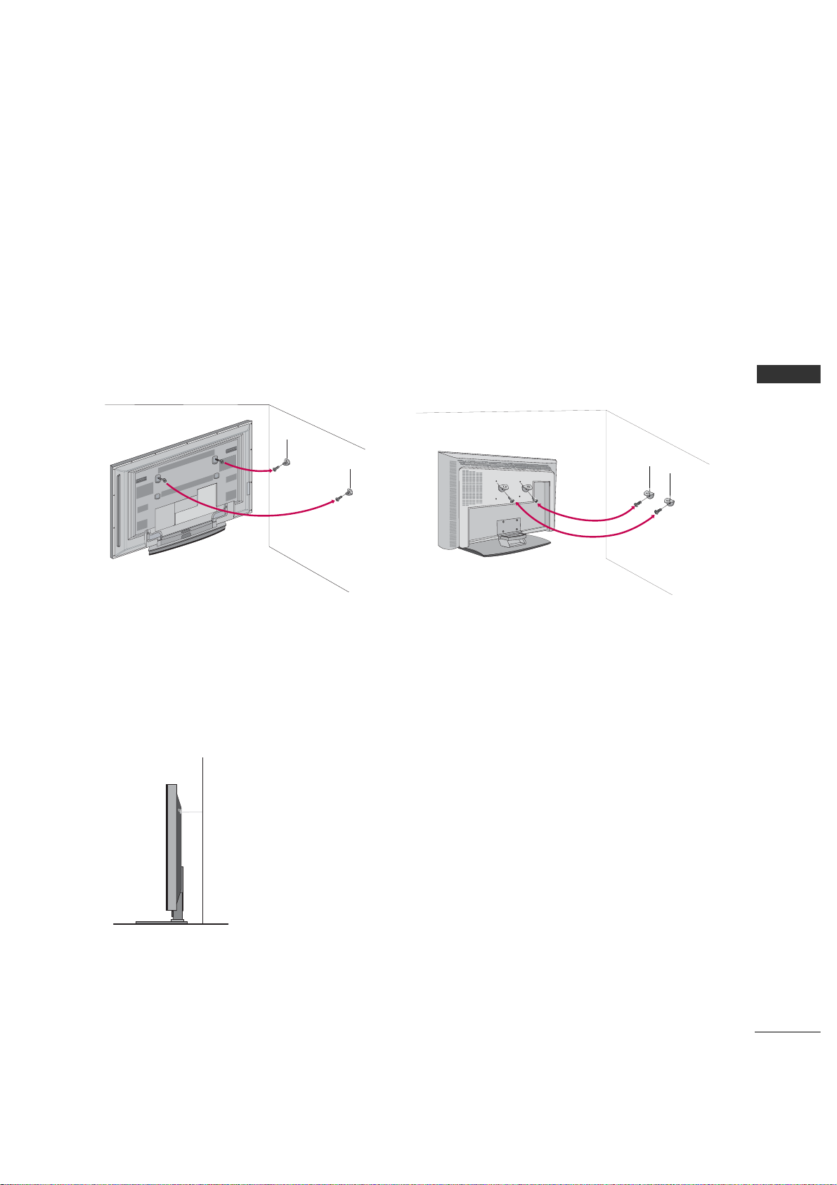
ATTACHING THE TV TO A WALL
We recommend that you set up the TV close to a wall so it cannot fall over if pushed backwards.
Additionally, we recommend that the TV be attached to a wall so it cannot be pulled in a forward direction,
potentially causing injury or damaging the product.
Caution: Please make sure that children don’t climb on or hang from the TV.
26LC2R*/32LC2R*42PC3RV*
■
Insert the eye-bolts (or TV brackets and bolts) to tighten the product to the wall as shown in the picture.
* If your product has the bolts in the eye-bolts position before inserting the eye-bolts, loosen the bolts.
Secure the wall brackets with the bolts (not provided as parts of the product, must purchase separately) on
the wall. Match the height of the bracket that is mounted on the wall to the holes in the product.
Ensure the eye-bolts or brackets are tightened securely.
■
Use a sturdy rope (not provided as parts of the product, must purchase
separately) to tie the product. It is safer to tie the rope so it becomes
horizontal between the wall and the product.
Page 18
INSTALLATION
BASIC CONNECTION
(For 42PC3RV*)
18
INSTALLATION
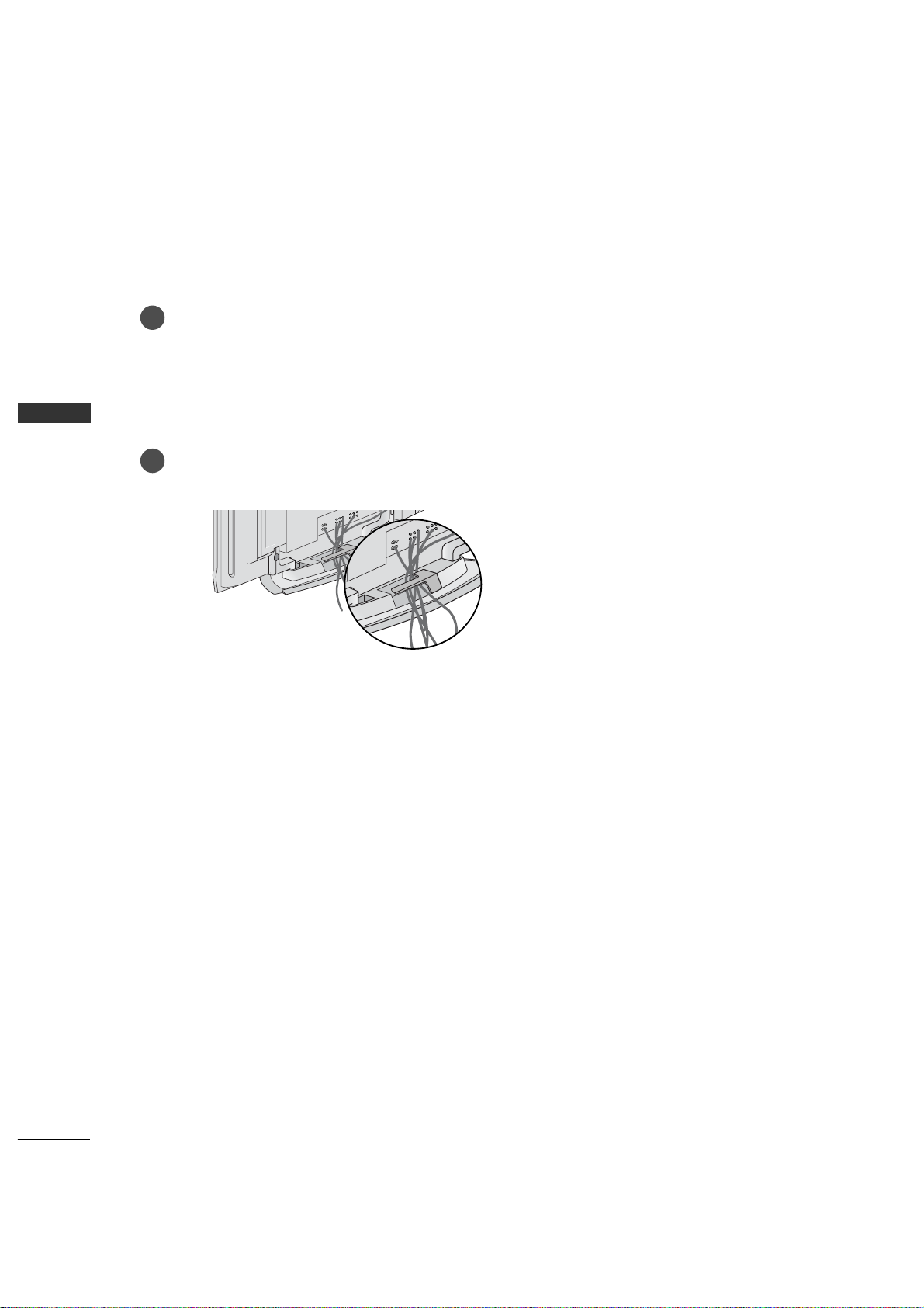
Arrange the cable as shown.
2
Connect the cables as necessary.
After connecting the cables neatly, arrange the cables to the Cable Holder.
To connect an additional equipment, see the Connections & Setup section.
1
Page 19
19
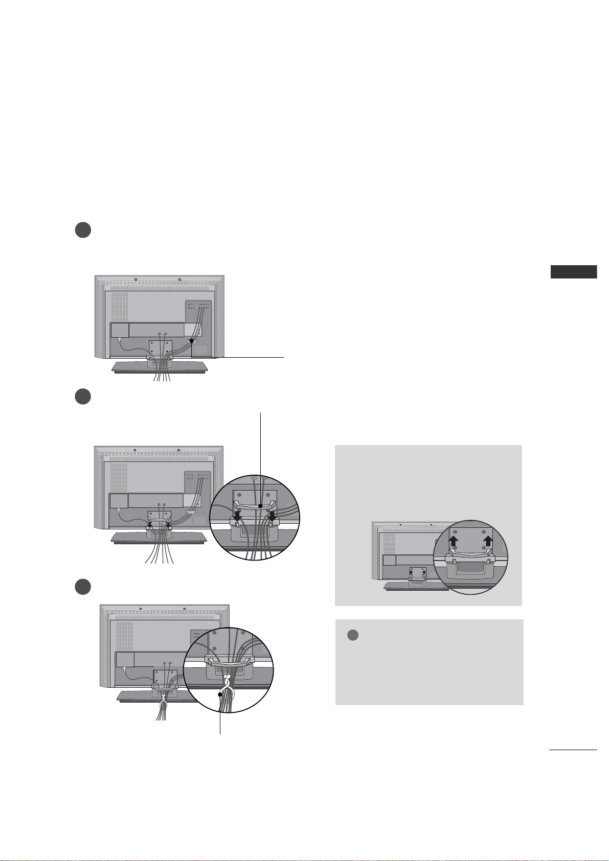
WIRE ARRANGEMENT
(Only 26/32LC2R*)
INSTALLATION
This function explains the features available on the 26/32LC2R.
Connect the cables as necessary.
After connecting the cables neatly, arrange the cables to the Cable Holder.
To connect an additional equipment, see the External equipment Connections section.
Install the CABLE MANAGEMENT as shown.
How to remove the CABLE
MANAGEMENT
G
Hold the CABLE MANAGEMENT
with both hands and pull it upward.
CABLE MANAGEMENT
G
Do not hold the CABLE MANAGEMENT
when moving the product.
- If the product is dropped, you may be
injured or the product may be broken.
NOTE
!
CABLE HOLDER
1
2
Bundle the cables using the supplied twister holder.
3
TWISTER HOLDER
Page 20
20
ANTENNA CONNECTION
CONNECTIONS & SETUP
CONNECTIONS & SETUP
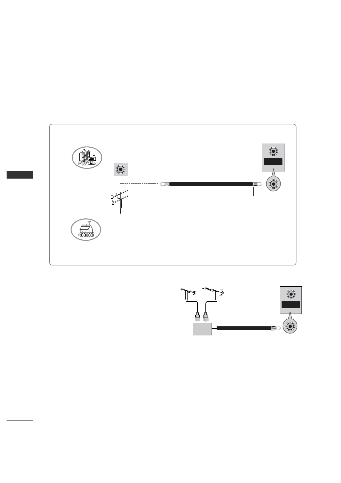
Wall Antenna Socket or Outdoor Antenna without a Cable Box Connections.
For optimum picture quality, adjust antenna direction if needed.
■
In poor signal areas, to get better picture quality,
install a signal amplifier to the antenna as
shown to the right.
■
If signal needs to be split for two TVs, use an
antenna signal splitter for connection.
Signal
Amplifier
UHF
VHF
Multi-family Dwellings/Apartments
(Connect to wall antenna socket)
Single-family Dwellings /Houses
(Connect to wall jack for outdoor antenna)
Outdoor Antenna
Wall Antenna Socket
VHF Antenna
UHF Antenna
RF Coaxial Wire (75 ohm)
Turn clockwise to tighten.
ANTENNA
IN
ANTENNA
IN
Page 21
CONNECTIONS & SETUP
21
■
To avoid picture noise (interference), leave an adequate distance between the VCR and TV
■
If the 4:3 picture format is used; the fixed images on the sides of the screen may remain visible on the
screen. This phenomenon is common to all manufactures and in consequence the manufactures warranty
does not cover the product bearing this phenomenon.
HDMI/DVI IN
UPGRADE
(MODULE)
AUDIO OUTAUDIO OUT
VARIABLE
S-VIDEO
OUT
IN
(R) AUDIO (L) VIDEO
34
OUTPUT
SWITCH
ANT OUT
ANT IN
ANTENNA
IN
VC R
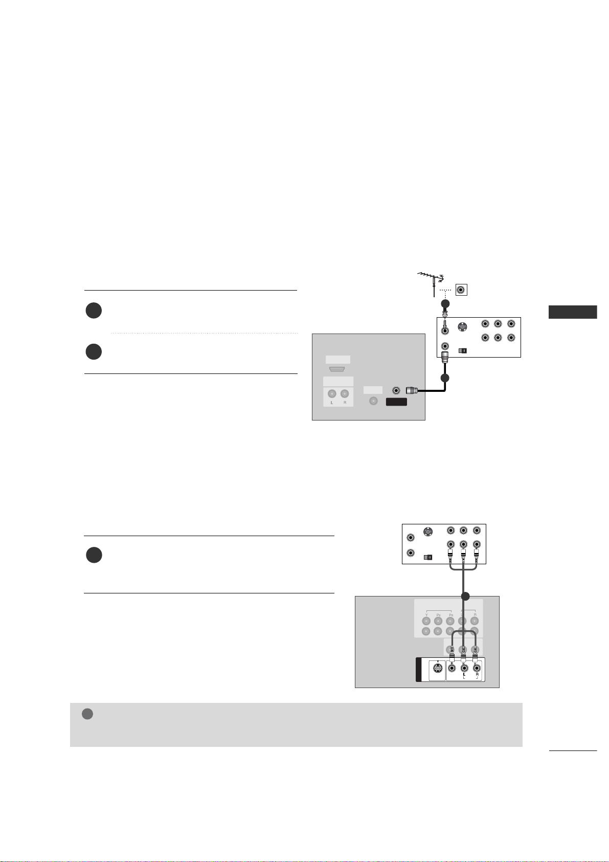
1
2
VCR SETUP
When connecting with an antenna
S-VIDEO
OUT
IN
(R) AUDIO (L) VIDEO
34
OUTPUT
SWITCH
ANT OUT
ANT IN
MONO
( )
AUDIO
VIDEO
S-VIDEOS-VIDEO
AV IN 1
VIDEO
AUDIO
COMPONENT IN
1
2
AV OUT
VC R
1
NOTE
!
G
If you have a mono VCR, connect the audio cable from the VCR to the
AUDIO LL/ M ON O
jack of the set.
Connect the RF antenna out socket of the VCR
to the
Ante n na
socket on the set.
Connect the antenna cable to the RF antenna
in socket of the VCR.
1. How to connect
2. How to use
■
Set VCR output switch to 3 or 4 and then tune
TV to the same channel number.
■
Insert a video tape into the VCR and press PLAY
on the VCR. (Refer to the VCR owner’s manual.
)
2
1
Connect the
AUD I O/VID E O
jacks between TV and
VCR. Match the jack colors (Video = yellow, Audio Left
= white, and Audio Right = red)
1. How to connect
2. How to use
■
Insert a video tape into the VCR and press PLAY on the
VCR. (Refer to the VCR owner’s manual.
)
■
Select
AV 1
input source with using the
INP U T
button on
the remote control.
■
If connected to
AV IIN 2
, select
AV2
input source.
1
When connecting with a RCA cable
Page 22
22
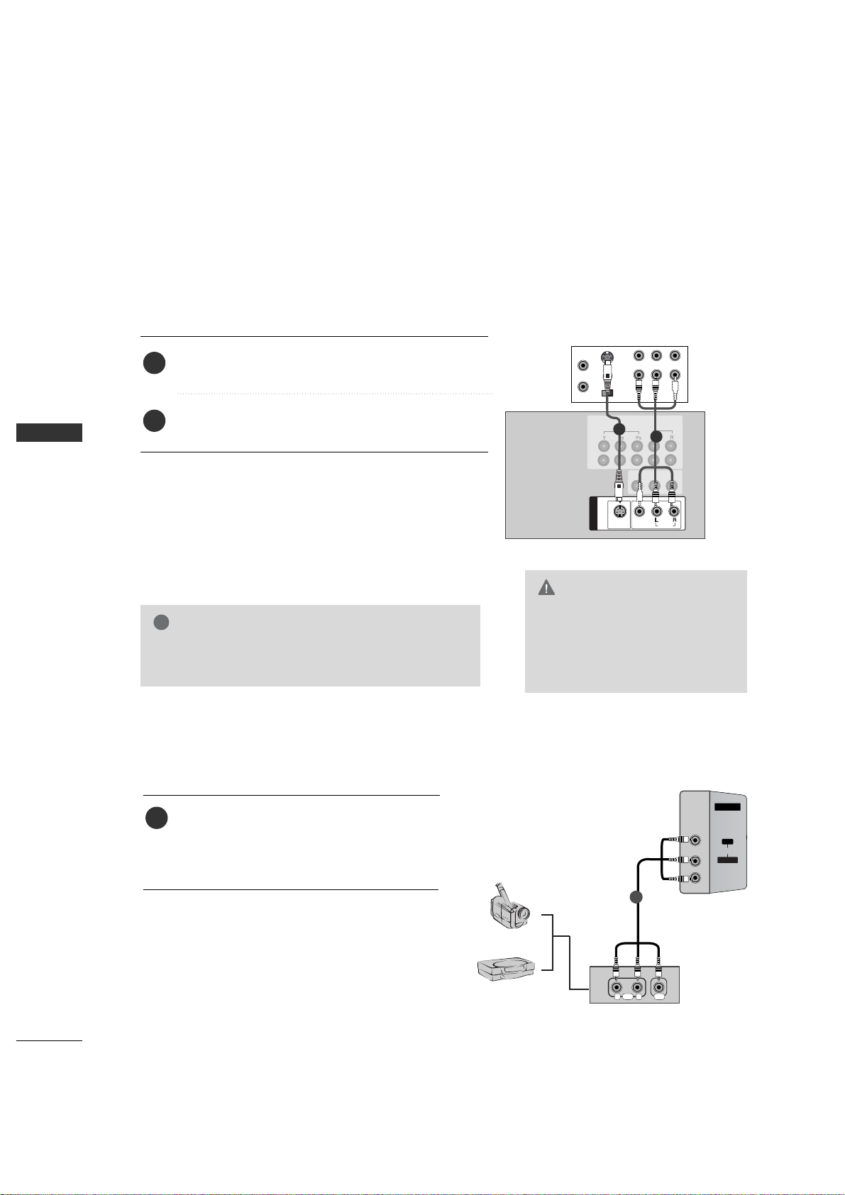
VCR SETUP
CONNECTIONS & SETUP
S-VIDEO
OUT
IN
(R) AUDIO (L) VIDEO
34
OUTPUT
SWITCH
ANT OUT
ANT IN
MONO
( )
AUDIOAUDIO
VIDEO
S-VIDEO
AV IN 1
VIDEO
AUDIO
COMPONENT IN
1
2
AV OUT
VC R
1
2
When connecting with an S-Video cable
AV IN 2
L/L/MONO
R
AUDIOAUDIO
VIDEOVIDEO
RL
AUDIO VIDEO
Camcorder
Video Game Set
1
EXTERNAL EQUIPMENT CONNECTIONS
G
The picture quality is improved: compared to normal
composite (RCA cable) input.
NOTE
!
Connect the S-VIDEO output of the VCR to the
S -V IDEO
input on the set.
Connect the audio outputs of the VCR to the
AUD I O
input jacks on the set.
1. How to connect
2. How to use
■
Insert a video tape into the VCR and press PLAY on the VCR.
(
Refer to the VCR owner’s manual.
)
■
Select
AV 1
input source with using the
INP U T
button on
the remote control.
■
If connected to
AV IIN 2
, select
AV2
input source.
2
1
G
Do not connect to both Video
and S-Video at the same time. In
the event that you connect both
Video and the S-Video cables,
only the S-Video will work.
CAUTION
Connect the
AUDIO/VIDEO
jacks between TV
and external equipment. Match the jack colors
.
(
Video = yellow, Audio Left = white, and Audio
Right = red
)
1. How to connect
2. How to use
■
Select
AV2
input source with using the
INP U T
button on the remote control.
■
If connected to
AV IIN 1
input, select
AV1
input
source.
■
Operate the corresponding external equipment.
1
Page 23
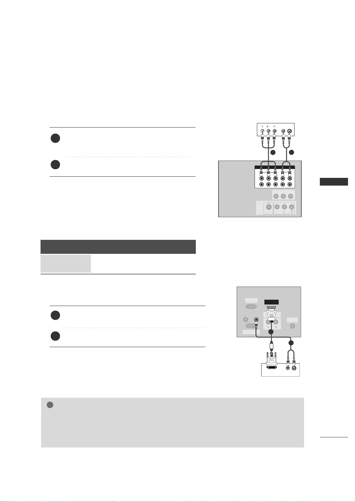
CONNECTIONS & SETUP
25
HDSTB SETUP
VIDEO
AUDIO
COMPONENT IN
1
2
B
R
(R) AUDIO (L)
MONO
( )
AUDIO
VIDEO
S-VIDEO
AV IN 1
AV OUT
Digital
Set-to p BBox
1
2
When connecting with a component cable
RGB IN
(PC/DTV)
RS-232C IN
(CONTROL&SERVICE)
UPGRADE
(MODULE)
AUDIO OUTAUDIO OUT
VARIABLE
HDMI/DVI IN
REMOTE
CONTROL IN
AUDIO IN
(RGB/DVI)
(R) AUDIO (L)
DVI-DTV OUTPUT
Digi t a l SS e t - t op
Box
1
2
When connecting with a HDMI to DVI cable
Connect the DVI output of the digital set-top box to the
HDM I IN
jack on the set.
Connect the audio output of the digital set-top box to the
AUDI O (RGB/ D VI
)
jack on the set.
1. How to connect
2. How to use
■
Turn on the digital set-top box. (Refer to the owner’s manual for
the digital set-top box.
)
■
Select
HDM I
input source with using the
INP U T
button on
the remote control.
2
1
G
If the digital set-top box supports Auto HDMI function, the output resolution of the source device will be
automatically set to 1280x720p.
G
If the digital set-top box player does not support Auto HDMI, you need to set the output resolution appropriately. To get the best picture quality, adjust the output resolution of the source device to 1280x720p.
NOTE
!
1. How to connect
Connect the video outputs (Y, PB, PR
)
of the digital set top
box to the
COMPONE N T II N VV ID E O
jacks on the set.
Match the jack colors (Y = green, P
B = blue, and PR = red).
Connect the audio output of the digital set-top box to
the
COMPONE N T II N AA U DI O
jacks on the set.
2
1
2. How to use
■
Turn on the digital set-top box.
(
Refer to the owner’s manual for the digital set-top box.
)
■
Select
Compon e nt 22
input source with using the
INP U T
button on the remote control.
■
If connected to
COMPON E N T II N1
input, select
Compon e nt 11
input source.
Signal
480i
480p/720p/1080i
Component 1/2
HDMI
Yes
Yes
RGB-DTV
No
Yes
Page 24
26
CONNECTIONS & SETUP
CONNECTIONS & SETUP
REMOTE
CONTROL IN
RS-232C INRS-232C IN
(CONTROL& SERVICE)
HDMI/DVI IN
UPGRADE
(MODULE)
AUDIO OUT
VARIABLE
RGB INRGB IN
(PC/DTV)
AUDIO IN
(RGB/DVI)
(R) AUDIO (L)
RGB-DTV OUTPUT
Digital
Set-to p BBox
1
2
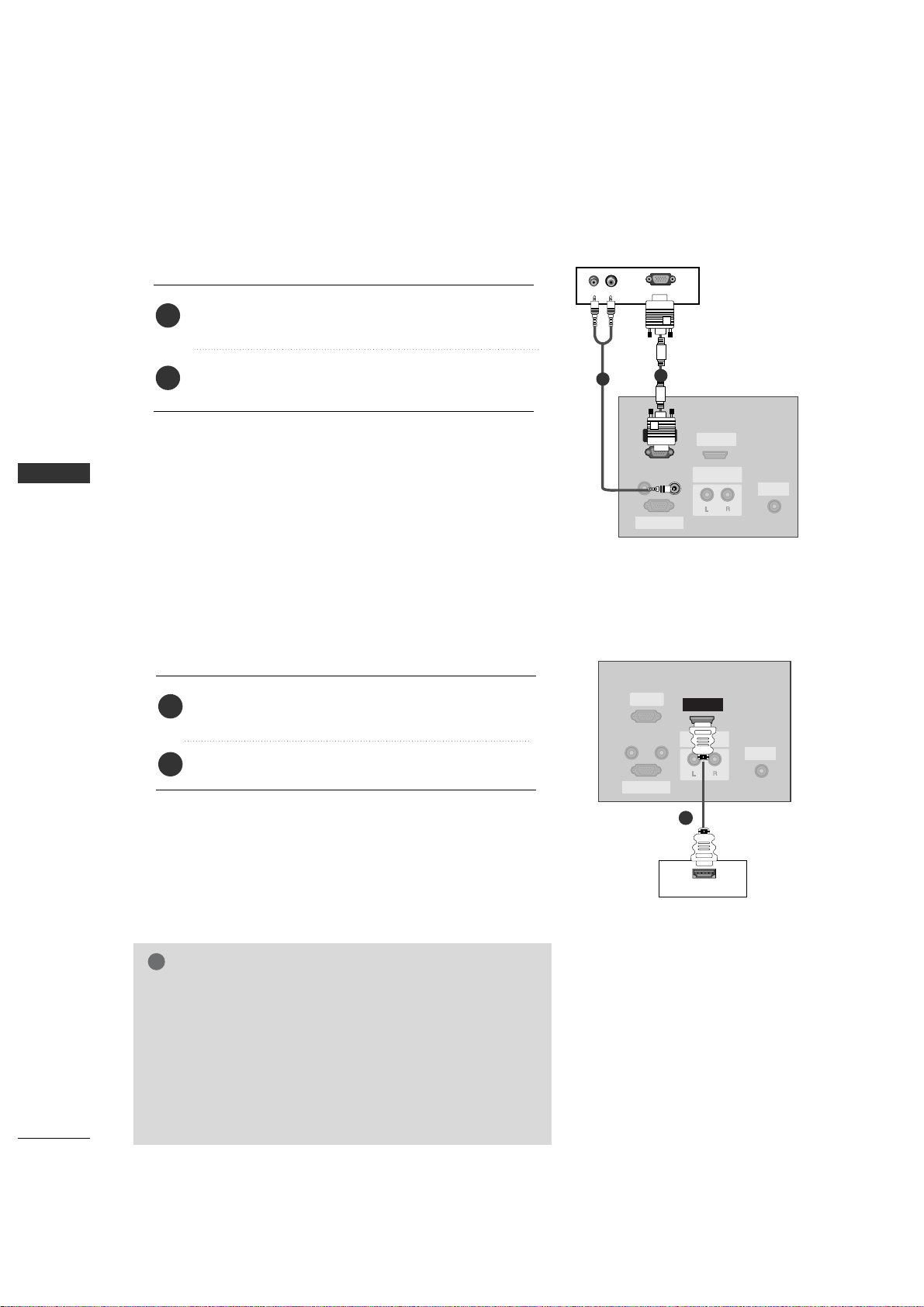
When connecting with a D-sub 15 pin cable
REMOTE
CONTROL IN
AUDIO IN
(RGB/DVI)
RGB INRGB IN
(PC/DTV)
RS-232C INRS-232C IN
(CONTROL& SERVICE)
UPGRADE
(MODULE)
AUDIO OUT
VARIABLE
HDMI/DVI IN
HDMI OUTPUT
1
When connecting with a HDMI cable
Digital
Set-to p BBox
Connect the RGB output of the digital set-top box to
the
RGB II N (PC/D T V
)
jack on the set.
Connect the audio outputs of the set-top box to the
AUDIO II N (RGB/ D VI
)
jack on the set.
1. How to connect
2. How to use
■
Turn on the digital set-top box.
(
Refer to the owner’s manual for the digital set-top box.
)
■
Select
RGB- D TV
input source with using the
INP U T
button on the remote control.
Connect the digital set-top box to
HDMI IIN
jack on
the set.
No separated audio connection is necessary.
1. How to connect
2. How to use
■
Turn on the digital set-top box.
(
Refer to the owner’s manual for the digital set-top box.
)
■
Select
HDM I
input source with using the
INP U T
button
on the remote control.
2
1
2
1
G
If the digital set-top box supports Auto HDMI function, the
output resolution of the source device will be automatically
set to 1280x720p.
G
If the digital set-top box player does not support Auto HDMI,
you need to set the output resolution appropriately.
To get the best picture quality, adjust the output resolution of
the source device to 1280x720p.
NOTE
!
Page 25
CONNECTIONS & SETUP
27
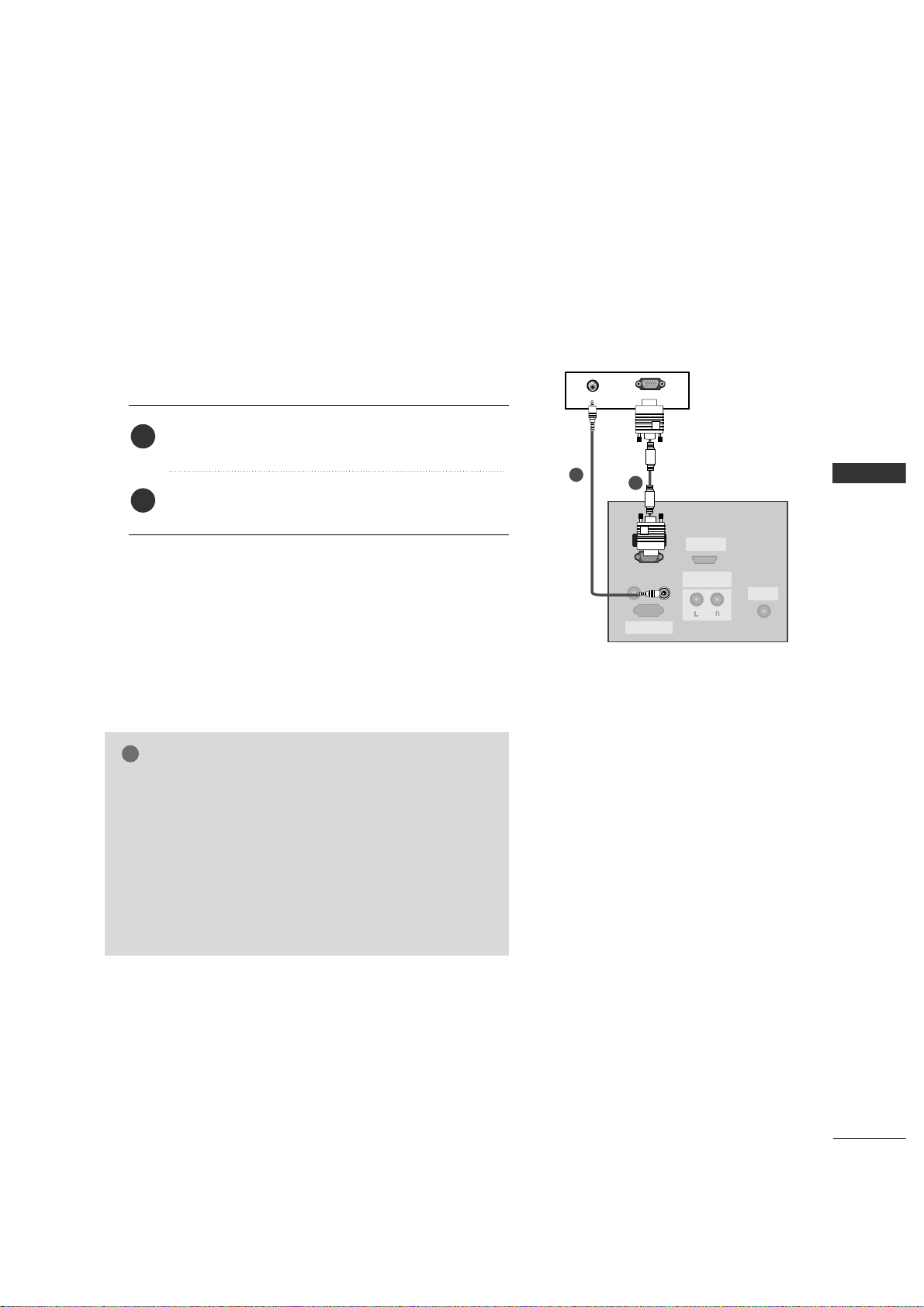
PC SETUP
REMOTE
CONTROL IN
RS-232C INRS-232C IN
(CONTROL& SERVICE)
HDMI/DVI IN
UPGRADE
(MODULE)
AUDIO OUT
VARIABLE
RGB INRGB IN
(PC/DTV)
AUDIO IN
(RGB/DVI)
AUDIO
RGB-PC OUTPUT
PC
1
2
■
This TV provides Plug and Play capability, meaning that the PC adjusts automatically to the TV's settings.
When connecting with a D-sub 15 pin cable
G
Check the image on your TV. There may be noise associated with the resolution, vertical pattern, contrast or
brightness in PC mode. If noise is present, change the PC
output to another resolution, change the refresh rate to
another rate or adjust the brightness and contrast on the
VIDEO menu until the picture is clear. If the refresh rate
of the PC graphic card can not be changed, change the
PC graphic card or consult the manufacturer of the PC
graphic card.
NOTE
!
Connect the RGB output of the PC to the
RGB II N
(
PC/D T V
)
jack on the set.
Connect the PC audio output to the
AUDIO II N
(
RGB/ D VI
)
jack on the set.
1. How to connect
2. How to use
■
Turn on the PC and the set.
■
Select
RGB- P C
input source with using the
INPU T
button
on the remote control.
2
1
Page 26
28
CONNECTIONS & SETUP
CONNECTIONS & SETUP
Horizontal Vertical
Frequency(KHz) Frequency(Hz)
31.5 70.1
31.5 70.1
31.5 59.9
37.9 60.3
48.4 60.0
47.8 59.9
47.7 59.8
47.7 59.8
Resolution
640x350
720x 400
640x 480
800x600
10 2 4 x 7 6 8
12 8 0 x 7 6 8
13 6 0 x 7 6 8
13 6 6 x 76 8
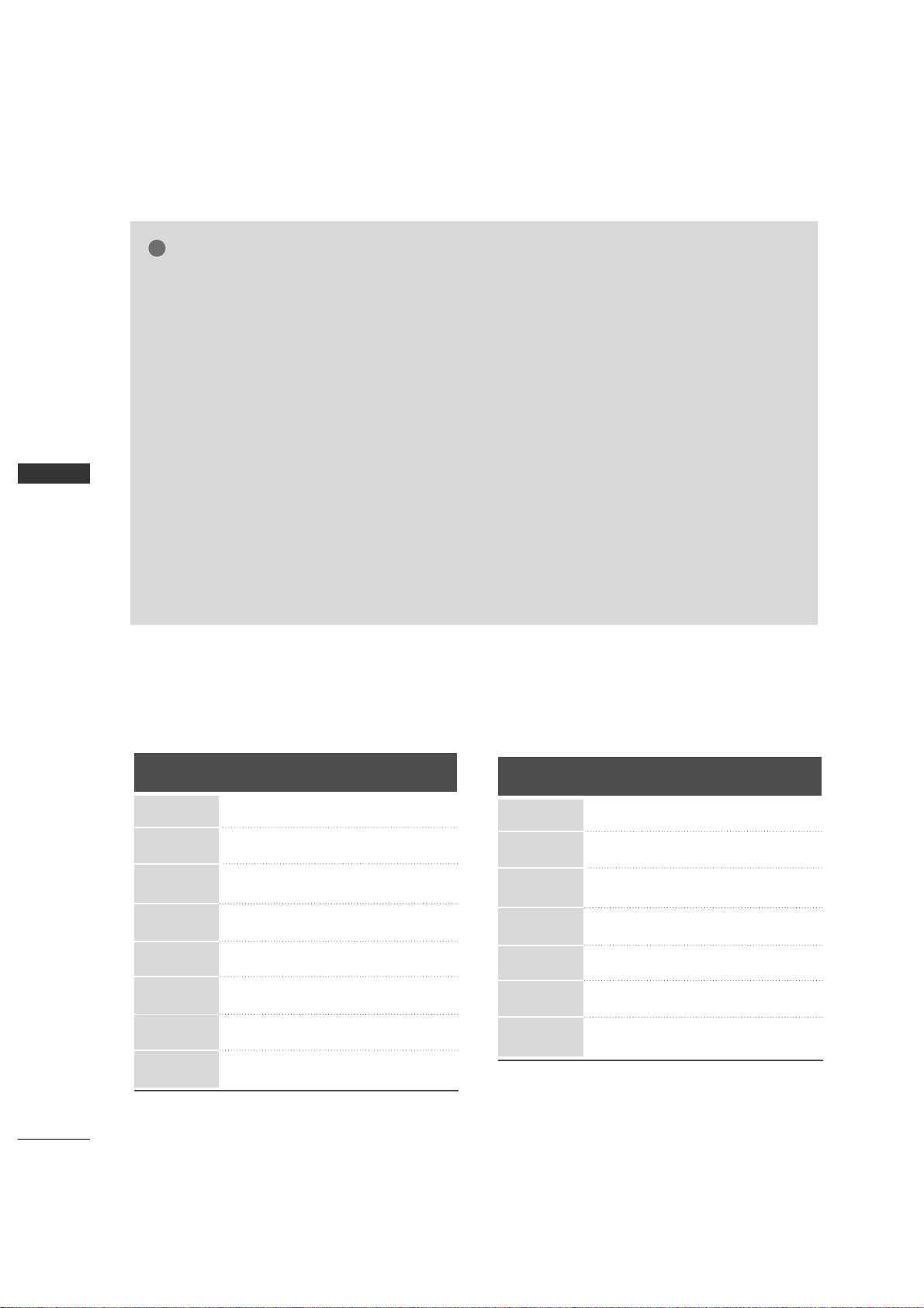
Supported Display Resolution (RGB[PC] mode)
(26/32LC2R)
Supported Display Resolution (RGB[PC] mode)
(42PC3RV)
Horizontal Vertical
Frequency(KHz) Frequency(Hz)
31.5 70.1
31.5 70.1
31.5 59.9
31.5 60.0
31.5 60.0
37.9 60.3
48.4 60.0
Resolution
640x350
720x400
640x480
848x480
852x480
800x600
10 2 4 x 7 6 8
NOTE
!
G
To get the the best picture quality, adjust the PC
graphics card to 640x480, 60Hz (42PC3RV)
/1360x768, 60Hz (26/32LC2R).
G
Depending on the graphics card, DOS mode may
not work if a HDMI to DVI Cable is in use.
G
When Source Devices connected with HDMI
Input, output TV SET Resolution (480p, 720p,
1080i) and TV SET Display fit EIA/CEA-861-B
Specification to Screen. If not, refer to the
Manual of HDMI Source Devices or contact your
service center.
G
If the HDMI Source Device is not connected to
the Cable or if there is a poor cable connection,
"No signal" is displayed in the HDMI Input. In
this case, that Video Resolution is not supported. If "Invalid Format" is displayed, refer to the
Source Device manual or contact your service
center.
G
Avoid keeping a fixed image on the screen for a
long period of time. The fixed image may
become permanently imprinted on the screen.
G
The synchronization input form for Horizontal
and Vertical frequencies is separate.
G
When you use too long RGB-PC cable, there
might be a noise on the screen. We recommend
using under 5m of the cable. It provides the best
picture quality.
G
This set does not support HDMI-PC
Page 27
BASIC OPERATION
29
BASIC OPERATION
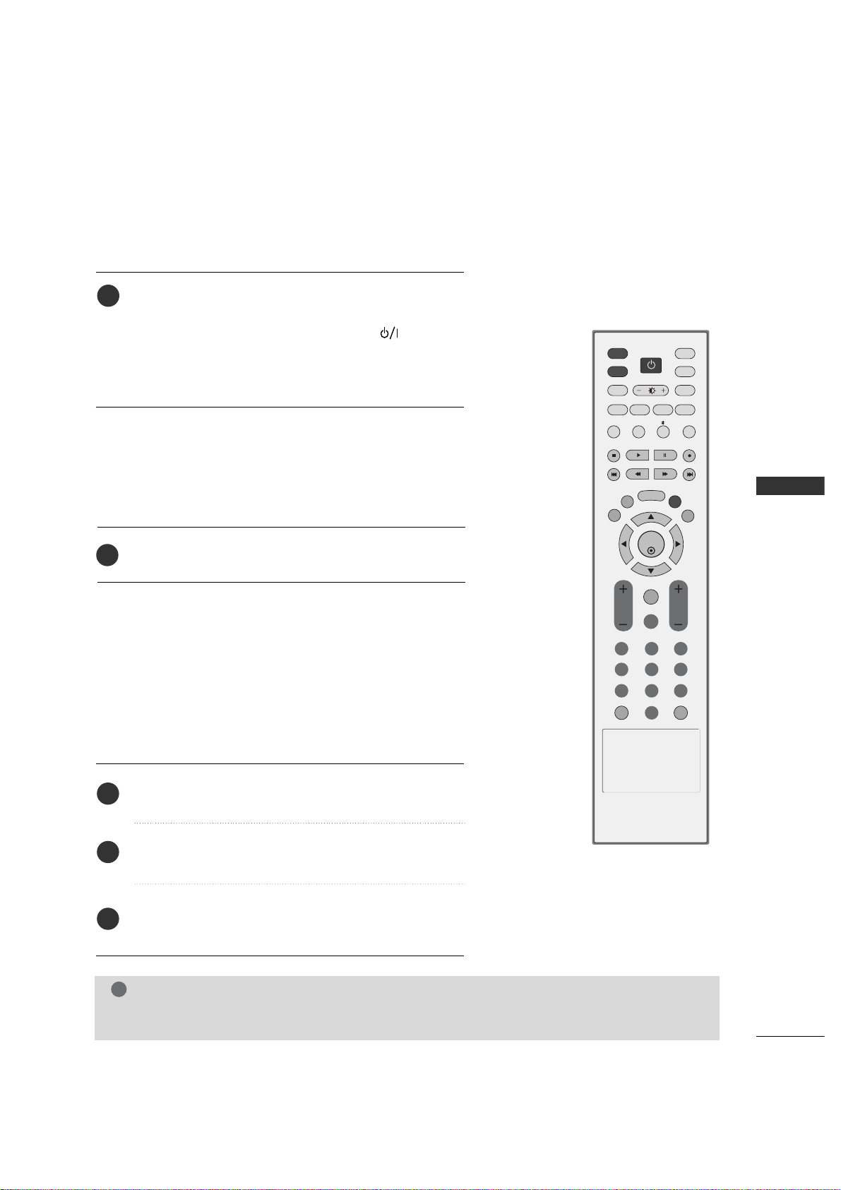
TURNING THE TV ON
First, connect power cord correctly.
At this moment, the TV switches to standby mode.
■
In standby mode to turn TV on, press the ,
INPUT
,
CH
D /E
button on the TV or press the
POWER, TV
,
INPUT, CH ++/-, Number(0~9)
button on the remote
control and then the TV will switch on.
VOL CH
CAPTION
ENTER
INPUT
TVTV
INPUT
PIP CH- PIP CH+
PIP INPUT
DVD
ARC
EXIT
REVIEW
MUTE
SLEEP
MEMORY/ERASE
MENU
PIP SIZE
POSTION
VCR
POWER
123
456
789
*
0
MTS
FCR
CAPTION
VOL CH
NOTE
!
G
If you intend to be away on vacation, disconnect the power plug from wall power outlet.
1
Press the
CH ++/-
or
NUMBER
buttons to select a
channel number.
1
VOLUME ADJUSTMENT
CHANNEL SELECTION
Press the
VOL ++/-
button to adjust the volume.
If you want to switch the sound off, press the
MUTE
button.
You can cancel the Mute function by pressing the
MUTE
or
VOL ++/-
or
MTS
button.
Adjust the volume to suit your personal preference.
1
2
3
Page 28
30
ON-SCREEN MENUS LANGUAGE SELECTION
BASIC OPERATION
BASIC OPERATION
Press the
MENU
button and then use D or E but-
ton to select the
Specia l
menu.
Press the
G
button and then use D or Ebutton to
select
Languag e .
Press the
G
button and then use D or E button to
select your desired language.
From this point on, the on-screen menus will be
shown in the selected language.
Press the
EXI T
button to return to TV viewing or
press
MENU
to return to the previous menu.
The menus can be shown on the screen in the selected language.
First select your language.
1
2
3
4
Page 29
SPECIAL FUNCTIONS/ PIP / TWIN PICTURE
31
SPECIAL FUNCTIONS
PIP / Twin Picture
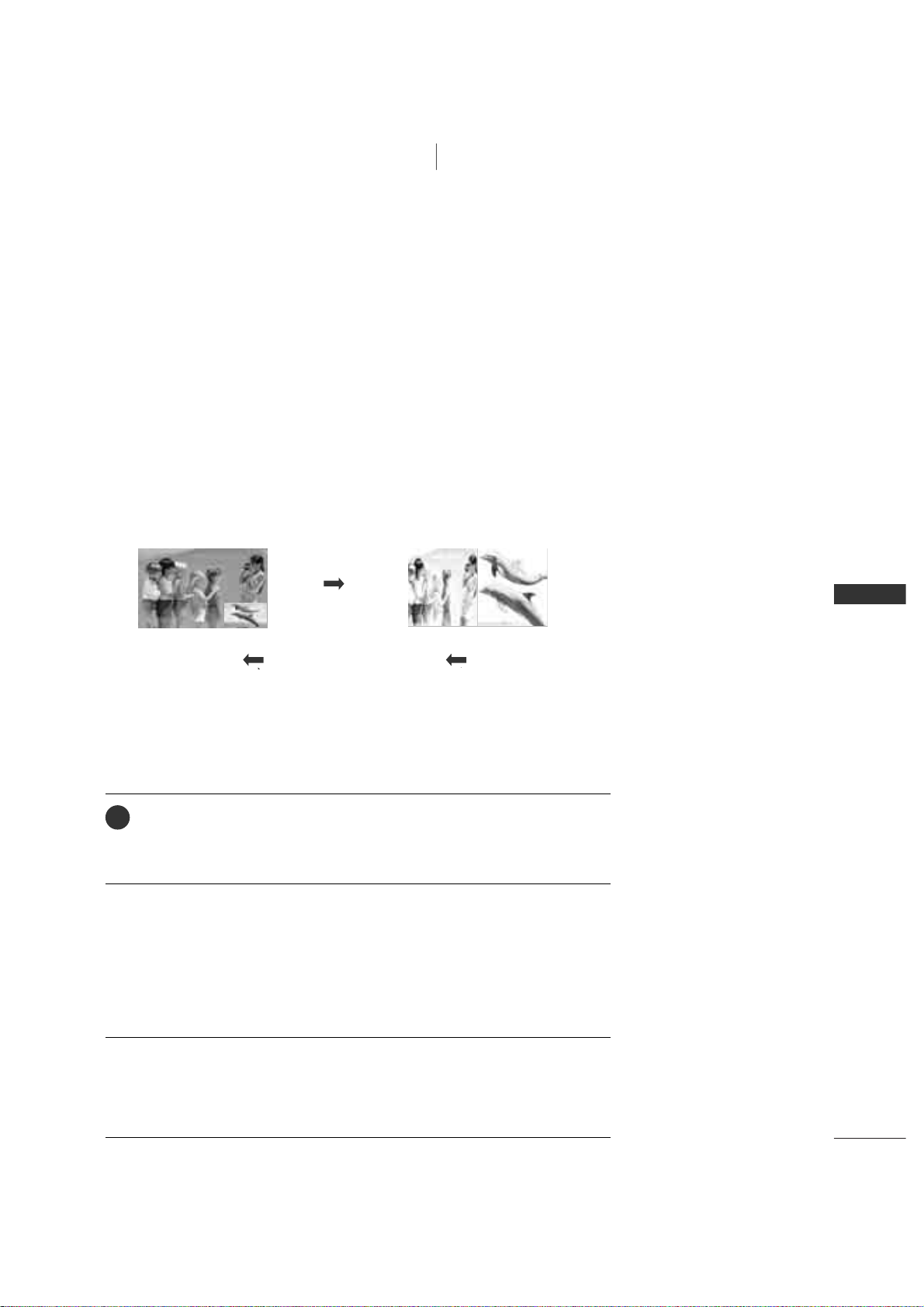
PIP lets you view 2 different inputs (sources) on your TV screen at the same time.
One source will be large, and the other source will show a smaller inset image.
Twin Picture mode splits the screen into two images, allowing two picture
sources to be shown on the TV screen at the same time. Each source is given
half the screen.
PIP function is available in the Component, RGB, HDMI mode. (But, it can’t
adjust 480i resolution of Component/HDMI mode.)
Watching PIP/Twin Picture
Press the
PI P
button to access the sub picture.
Each press of PIP changes the PIP options as shown below.
PIP Mode Twin Picture Mode
PIP Off
TV Program Selection for PIP
Use the
PIP CCH ++/-
button to select a channel for the sub picture.
The selected channel number is displayed just below the channel number of
main picture.
1
Selecting an Input Signal Source for PIP/Twin Picture
Use the
PIP II N P UT
button to select the input source for the sub picture.
Each press of
PIP II N P UT
button changes the PIP source.
Page 30
32
SPECIAL FUNCTIONS/ PIP / TWIN PICTURE
SPECIAL FUNCTIONS
ENTER
INPUT
TVTV
INPUT
PIP CH- PIP CH+
PIP INPUT
DVD
ARC
EXIT
SLEEP
MEMORY/ERASE
MENU
CAPTION
PIP SIZE
POSTION
VCR
POWER
MTS
PIP / Twin Picture
Sub Picture Size Adjustment (PIP mode only)
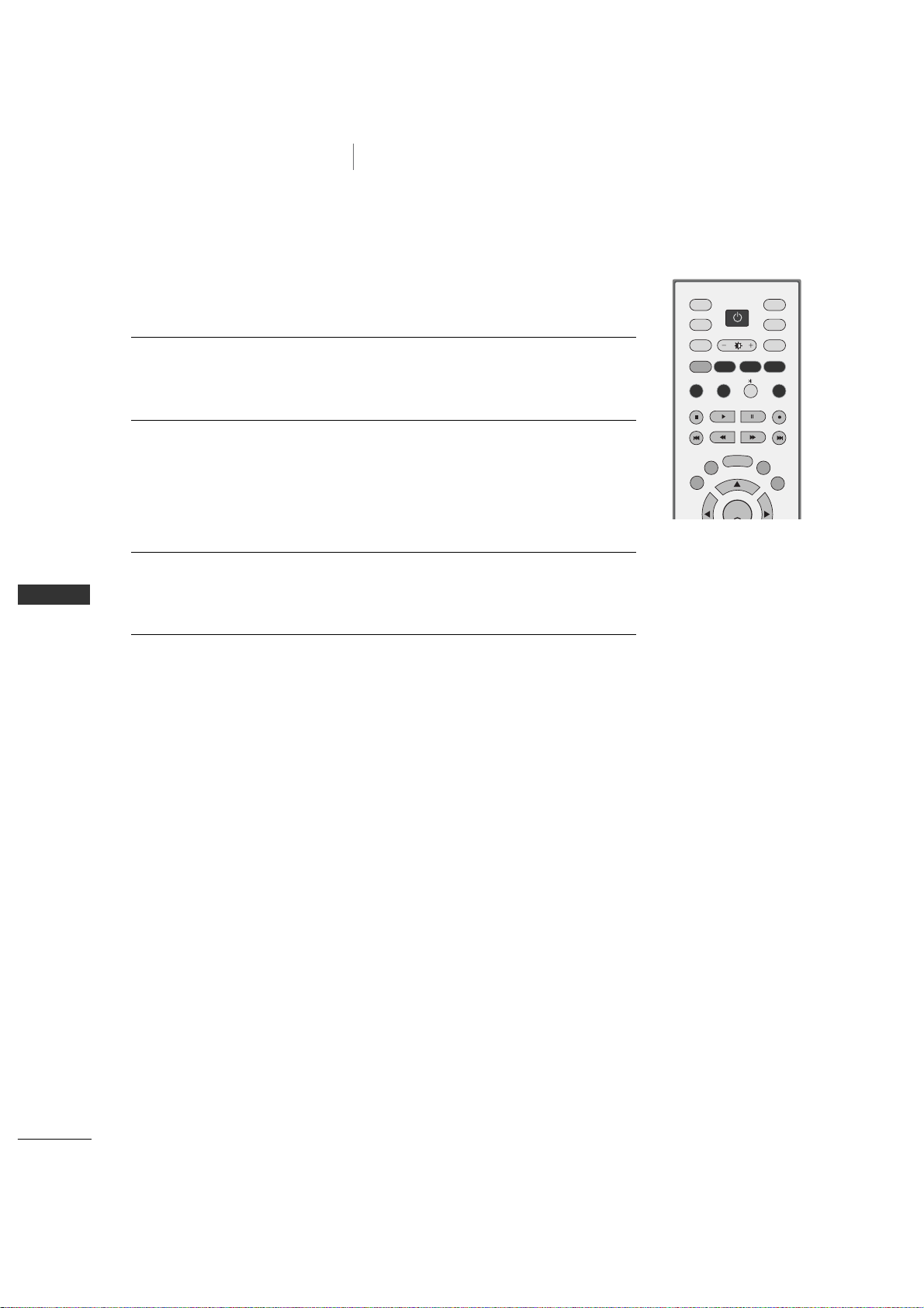
Press the
SIZ E
button to adjust the sub picture size.
With
SIZ E
button in PIP mode, sub picture is adjusted.
Moving the Sub Picture (PIP mode only)
Press the
POSI T I ON
button.
Repeatedly press the
POSIT I ON
button then sub picture moves.
Page 31
APPENDIX
73
EXTERNAL CONTROL DEVICE SETUP
APPENDIX
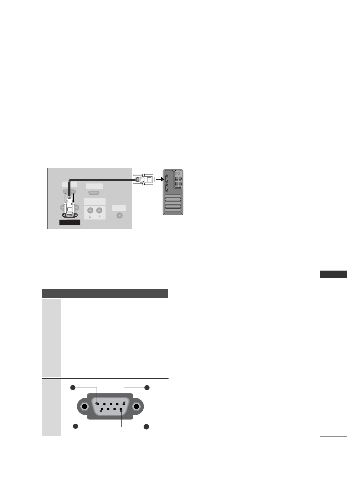
RS-232C Setup
Connect the RS-232C (serial port) input jack to an external control device (such as a computer or an A/V control system) to control the product’s functions externally.
Connect the serial port of the control device to the RS-232C jack on the product back panel.
Note: RS-232C connection cables are not supplied with the product.
REMOTE
CONTROL IN
AUDIO IN
(RGB/DVI)
RGB INRGB IN
(PC/DTV)
HDMI/DVI IN
UPGRADE
(MODULE)
AUDIO OUTAUDIO OUT
VARIABLE
RS-232C IN
(CONTROL& SERVICE)
PC
Type of Connector; D-Sub 9-Pin Male
No. Pin Name
1 No connection
2 RXD (Receive data
)
3 TXD (Transmit data
)
4 DTR (DTE side ready
)
5 GND
6 DSR (DCE side ready
)
7 RTS (Ready to send
)
8 CTS (Clear to send
)
9 No Connection
9
1
5
6
Page 32
74
APPENDIX
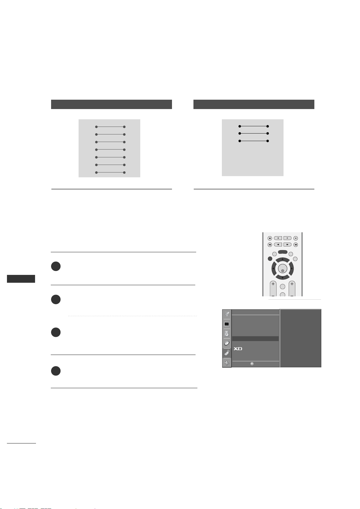
RS-232C Configurations
7-Wire Configurations (Standard RS-232C cable
)
PC TV
RXD 2 3 TXD
TXD 3 2 RXD
GND 5 5 GND
DTR 4 6 DSR
DSR 6 4 DTR
RTS 7 8 CTS
CTS 8 7 RTS
D-Sub 9 D-Sub 9
3-Wire Configurations(Not standard
)
PC TV
RXD 2 3 TXD
TXD 3 2 RXD
GND 5 5 GND
DTR 4 6 DTR
DSR 6 4 DSR
RTS 7 7 RTS
CTS 8 8 CTS
D-Sub 9 D-Sub 9
Special
DE F G
MENU
Language
Key lock
ISM Method
Low Power
Set ID
G
Caption
Demo
1
APPENDIX
Press the
MENU
button and then useD or E button
to select the
Special
menu.
Press the
G
button and then useD or E button to
select
Set IID
.
Press the
G
button and then use
F/ G
button to
adjust
Set IID
to choose the desired TV ID number.
The adjustment range of Set ID is 1~99.
Press
EXIT
button to return to TV viewing or press
MENU
button to return to the previous menu.
Use this function to specify a TV ID number.
Refer to ‘Real Data Mapping 1’.
G
p.78
.
Set ID
Communication Parameters
■
Baud rate : 9600 bps (UART
)
■
Data length : 8 bits
■
Parity : None
■
Stop bit : 1 bit
■
Communication code : ASCII code
■
Use a crossed (reverse) cable.
2
1
3
4
MENU
ENTER
REVIEW
MUTE
MTS
CH
MEMORY/ERASE
EXIT
VOL
SLEEP
Page 33
84
APPENDIX
APPENDIX
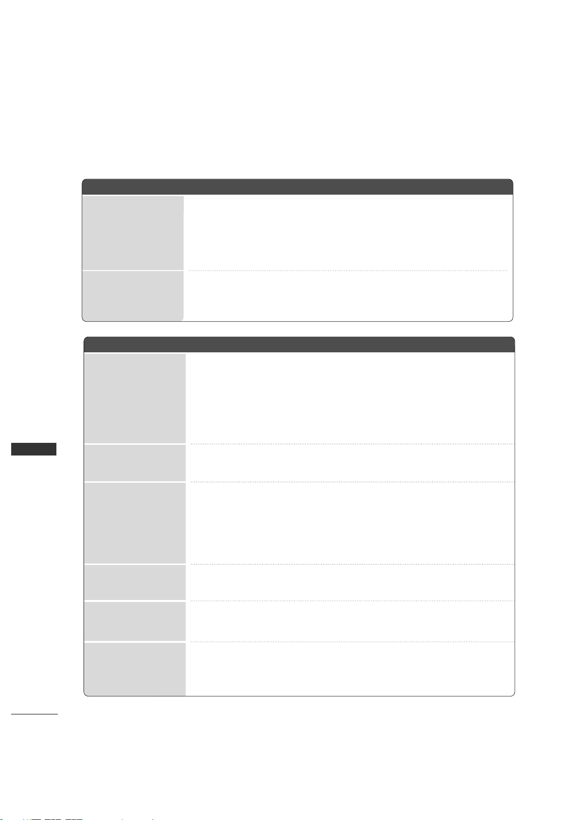
TROUBLESHOOTING CHECKLIST
The oo p e ra t i on ddoes nn o t wwork nnorm a l l y.
The rremo t e ccont r o l
doesn’ t wwork
Power iis ssu d d en l y
turne d ooff
The vvideo ffun c t i on ddoes nn o t wwork.
No pp i ct u re &&
No ss o u nd
No oo r ppoo r cc o l or
or pp o or ppic t u re
Poor rrec e p ti o n oon
some cchan n e ls
Lines oor sst r e ak s iin
p
ictu r e s
Horizontal/vertical
bars oor ppicture sshaking
Picture aappe a r s ssl ow-
ly aa f te r ss wi t ch i n g oon
■
Check whether the product is turned on.
■
Try another channel. The problem may be with the broadcast.
■
Is the power cord inserted into wall power outlet?
■
Check your antenna direction and/or location.
■
Test the wall power outlet, plug another product’s power cord into the outlet
where the product’s power cord was plugged in.
■
This is normal, the image is muted during the product startup process. Please
contact your service center, if the picture has not appeared after five minutes.
■
Adjust Color in menu option.
■
Keep a sufficient distance between the product and the VCR.
■
Try another channel. The problem may be with the broadcast.
■
Are the video cables installed properly?
■
Activate any function to restore the brightness of the picture.
■
Check for local interference such as an electrical appliance or power tool.
■
Station or cable product experiencing problems, tune to another station.
■
Station signal is weak, reorient antenna to receive weaker station.
■
Check for sources of possible interference.
■
Check antenna (Change the direction of the antenna).
■
Check to see if there is any object between the product and the remote control
causing obstruction.
■
Are batteries installed with correct polarity (+ to +, - to -)?
■
Correct remote operating mode set: TV, VCR etc.?
■
Install new batteries.
■
Is the sleep timer set?
■
Check the power control settings. Power interrupted
■
No broadcast on station tuned with Auto off activated.
Page 34
APPENDIX
85
■
Press the
VOL ++ /- ((or VVo l u me )
button.
■
Sound muted? Press
MUT E
button.
■
Try another channel. The problem may be with the broadcast.
■
Are the audio cables installed properly?
■
Adjust Balance in menu option.
■
A change in ambient humidity or temperature may result in an unusual noise
when the product is turned on or off and does not indicate a fault with the
product.
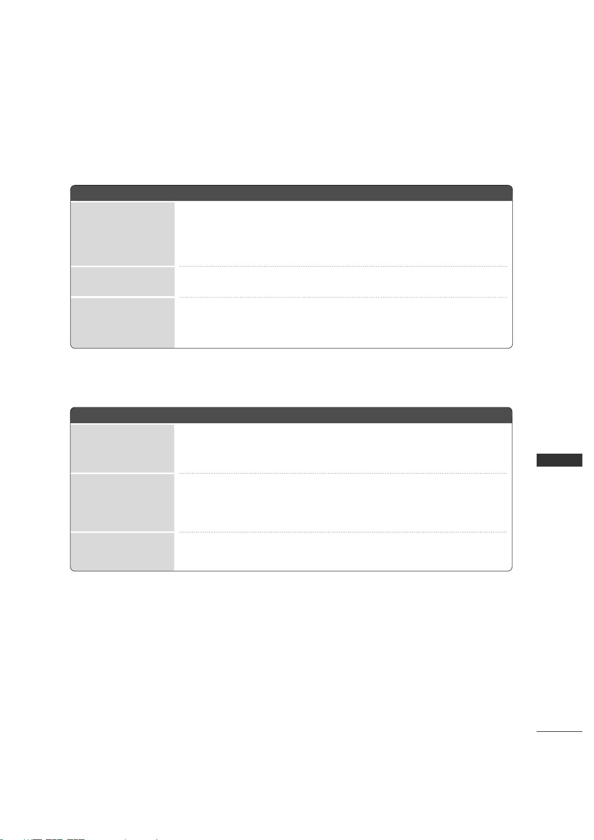
Pictur e OOK &&
No ss o u nd
Unusual ssound ffrom
inside tthe pprodu c t
No oo u t pu t ffrom oone
of tthe ssp e a ke r s
There iis aa pprob l e m iin PPC mmod e . ((Only PPC mmo de aappli e d )
■
Adjust resolution, horizontal frequency, or vertical frequency.
■
Check the input source.
■
Work the Auto configure or adjust clock, phase, or H/V position.
■
Check the signal cable.
■
Reinstall the PC video card.
The ss i g na l iis oout oo f
rang e .
Screen cco l o r iis
unstabl e oor ss in g le
col o r
Vertic a l bbar oo r
stripe oon bback-
ground && HHorizo n t al
Noise && IIn c o rr e c t
posit i on
The aa ud i o ffunct i o n ddoes nnot wwork.
Page 35
86
APPENDIX
APPENDIX
MAINTENANCE
Early malfunctions can be prevented. Careful and regular cleaning can extend the amount of time you will
have your new TV. Be sure to turn the power off and unplug the power cord before you begin any cleaning.
Cleaning the Screen
Here’s a great way to keep the dust off your screen for a while. Wet a soft cloth in a mixture of lukewarm
water and a little fabric softener or dish washing detergent. Wring the cloth until it’s almost dry, and then
use it to wipe the screen.
Make sure the excess water is off the screen, and then let it air-dry before you turn on your TV.
Cleaning the Cabinet
■
To remove dirt or dust, wipe the cabinet with a soft, dry, lint-free cloth.
■
Please be sure not to use a wet cloth.
Extended Absence
If you expect to leave your TV dormant for a long time (such as a vacation), it’s a good idea to unplug
the power cord to protect against possible damage from lightning or power surges.
CAUTION
1
2
Page 36
APPENDIX
87
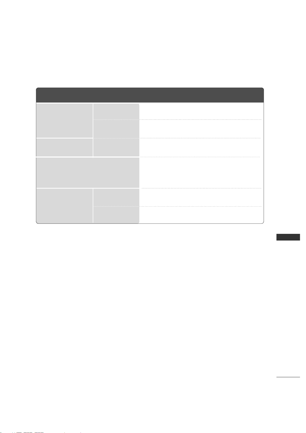
PRODUCT SPECIFICATIONS
26LC2R
(26LC2R-UJ)
32LC2R
(32LC2R-UJ)
MODELS
32 ~ 104°F (0 ~ 40°C)
Less than 80%
-4 ~ 140°F (-20 ~ 60°C)
Less than 85%
AC100-240V -50/60Hz, 1.3A
NTSC
VHF 2
~ 13, UHF 14 ~ 69, CATV 1 ~ 13 5
75 ohm
Dimensions
(Width x Height x Depth)
Weight
Power requirement
Television System
Program Coverage
External Antenna Impedance
Environment condition
including stand
excluding stand
including stand
excluding stand
Operating Temperature
Operating Humidity
Storage Temperature
Storage Humidity
26.8 x 21.3 x 6.8 inches
681.0 x 542.0 x 172.0 mm
26.8 x 19.3 x 4.6 inches
681.0 x 490.8 x 119.0 mm
40.8 pounds / 18.5 kg
33.5 pounds / 15.2 kg
31.9 x 24.8 x 9.3 inches
811.0 x 630.0 x 235.0 mm
31.9 x 22.3 x 4.9 inches
811.0 x 566.8 x 123.5 mm
48.2 pounds / 21.9 kg
40.8 pounds / 18.5 kg
■
The specifications shown above may be changed without prior notice for quality improvement.
AC100-240V -50/60Hz, 1.5A
Page 37
88
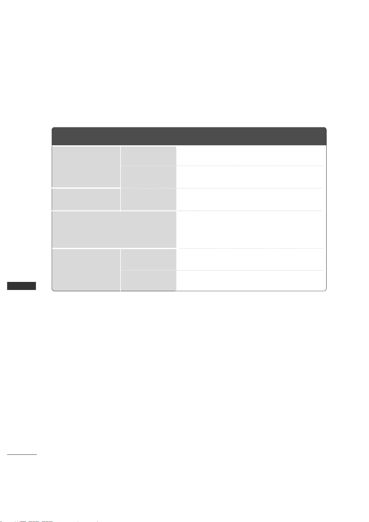
PRODUCT SPECIFICATIONS
APPENDIX
42PC3RV
(42PC3RV-UJ)
MODELS
AC100-240V -50/60Hz, 2.8A
NTSC
VHF 2
~ 13, UHF 14 ~ 69, CATV 1 ~ 13 5
75 ohm
32 ~ 104°F (0 ~ 40°C)
Less than 80%
-4 ~ 140°F (-20 ~ 60°C)
Less than 85%
Dimensions
(Width x Height x Depth)
Weight
Power requirement
Television System
Program Coverage
External Antenna Impedance
Environment condition
including stand
excluding stand
including stand
excluding stand
Operating Temperature
Operating Humidity
Storage Temperature
Storage Humidity
44.4 x 29.5 x 15.0 inches
1129.0 x 748.5 x 380.0 mm
44.4 x 27.4 x 4.1 inches
1129.0 x 695.0 x 103.7 mm
62.6 pounds / 28.4 kg
54.0 pounds / 24.5 kg
■
The specifications shown above may be changed without prior notice for quality improvement.
 Loading...