

Page 1

LCD TV
OWNER’S MANUAL
19LH20R
22LH20R
26LH20R
32LH20R
37LH20R
42LH20R
32LF20FR
42LF20FR
Please read this manual carefully before operating
your set and retain it for future reference.
The model and serial number of the TV is located
on the back and one side of the TV.
Record it below should you ever need service.
Model:
Serial:
32LH30FR
37LH30FR
42LH30FR
47LH30FR
42LH50YR
47LH50YR
55LH50YR
19LU50R
22LU50FR
26LU50FR
32LH70YR
42LH70YR
47LH70YR
42LH90QR
47LH90QR
P/NO : MFL58486305 (0904-REV06)
www.lge.com
Page 2
WARNING / CAUTION
TO REDUCE THE RISK OF ELECTRIC SHOCK
DO NOT REMOVE COVER (OR BACK). NO
USER SERVICEABLE PARTS INSIDE. REFER TO
QUALIFIED SERVICE PERSONNEL.
The lightning flash with arrowhead
symbol, within an equilateral triangle, is
intended to alert the user to the presence
of uninsulated “dangerous voltage” within the
product’s enclosure that may be of sufficient
magnitude to constitute a risk of electric shock to
persons.
The exclamation point within an equilateral
triangle is intended to alert the user to
the presence of important operating
and maintenance (servicing) instructions in the
literature accompanying the appliance.
WARNING/CAUTION
TO REDUCE THE RISK OF FIRE AND ELECTRIC
SHOCK, DO NOT EXPOSE THIS PRODUCT TO
RAIN OR MOISTURE.
2
Page 3
SAFETY INSTRUCTIONS
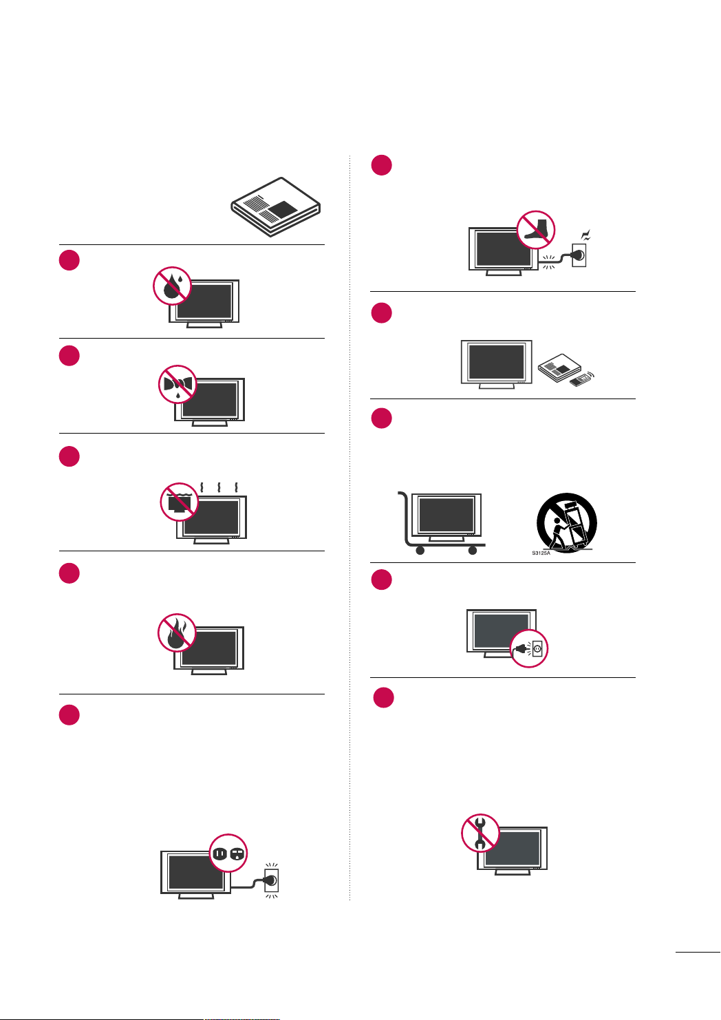
IMPORTANT SAFETY INSTRUCTIONS
Read these instructions.
Keep these instructions.
Heed all warnings.
Follow all instructions.
Do not use this apparatus near water.
1
Clean only with dry cloth.
2
Do not block any ventilation openings. Install in
3
accordance with the manufacturer’s instructions.
Protect the power cord from being walked on
6
or pinched particularly at plugs, convenience
receptacles, and the point where they exit from
the apparatus.
Only use attachments/accessories specified by
7
the manufacturer.
Use only with the cart, stand, tripod, bracket,
8
or table specified by the manufacturer, or sold
with the apparatus. When a cart is used, use
caution when moving the cart/apparatus combination to avoid injury from tip-over.
Do not install near any heat sources such as
4
radiators, heat registers, stoves, or other
apparatus (including amplifiers)that produce
heat.
Do not defeat the safety purpose of the polarized
5
or grounding-type plug. A polarized plug has
two blades with one wider than the other. A
grounding type plug has two blades and a
third grounding prong, The wide blade or the
third prong are provided for your safety. If the
provided plug does not fit into your outlet,
consult an electrician for replacement of the
obsolete outlet.
Unplug this apparatus during lighting storms
9
or when unused for long periods of time.
Refer all servicing to qualified service personnel.
10
Servicing is required when the apparatus has
been damaged in any way, such as powersupply cord or plug is damaged, liquid has
been spilled or objects have fallen into the
apparatus, the apparatus has been exposed to
rain or moisture, does not operate normally, or
has been dropped.
3
Page 4
SAFETY INSTRUCTIONS
Owner Manual
Never touch this apparatus or antenna during
11
a thunder or lighting storm.
When mounting a TV on the wall, make sure
12
not to install the TV by the hanging power and
signal cables on the back of the TV.
Do not allow an impact shock or any objects to
13
fall into the product, and do not drop onto the
screen with something.
CAUTION concerning the Power Cord:
14
It is recommend that appliances be placed
upon a dedicated circuit; that is, a single
outlet circuit which powers only that appliance
and has no additional outlets or branch
circuits. Check the specification page of this
owner's manual to be certain.
Do not connect too many appliances to the
same AC power outlet as this could result in
fire or electric shock.
Do not overload wall outlets. Overloaded wall
outlets, loose or damaged wall outlets, extension
cords, frayed power cords, or damaged or
cracked wire insulation are dangerous. Any of
these conditions could result in electric shock
or fire. Periodically examine the cord of your
appliance, and if its appearance indicates damage
or deterioration, unplug it, discontinue use of
the appliance, and have the cord replaced with
an exact replacement part by an authorized
servicer. Protect the power cord from physical
or mechanical abuse, such as being twisted,
kinked, pinched, closed in a door, or walked
upon. Pay particular attention to plugs, wall
outlets, and the point where the cord exits the
appliance.
Do not make the TV with the power cord
plugged in. Do not use a damaged or loose
power cord. Be sure do grasp the plug when
unplugging the power cord. Do not pull on the
power cord to unplug the TV.
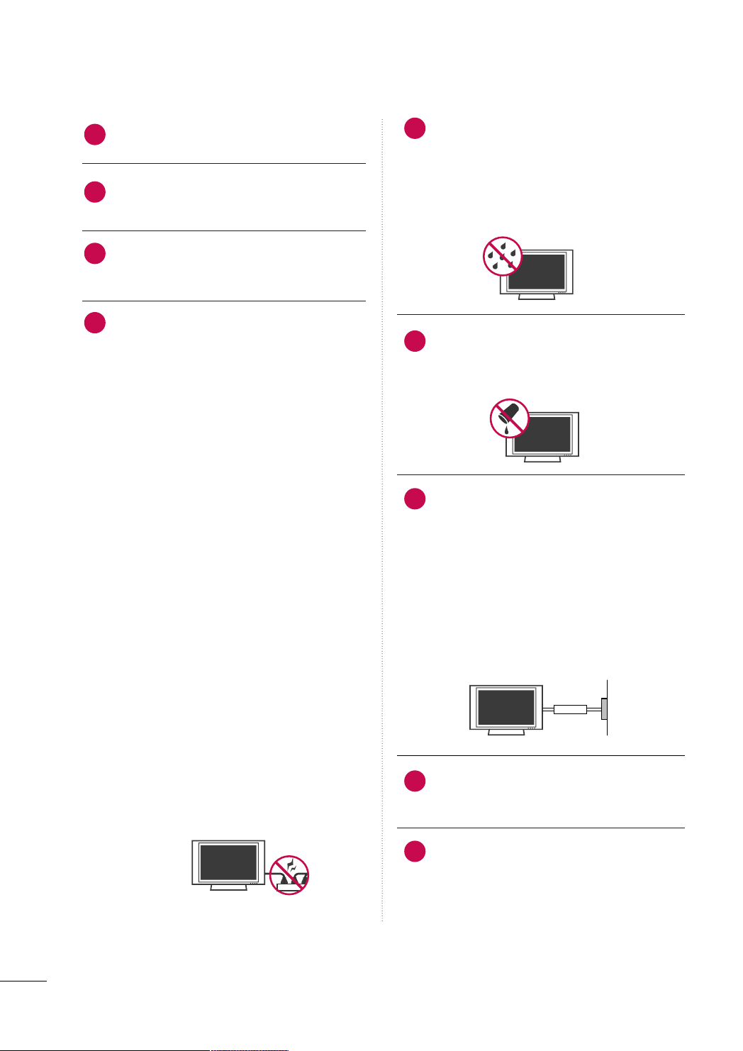
WARNING - To reduce the risk of fire or electrical
15
shock, do not expose this product to rain,
moisture or other liquids. Do not touch the TV
with wet hands. Do not install this product
near flammable objects such as gasoline or
candles or expose the TV to direct air
conditioning.
Do not expose to dripping or splashing and do
16
not place objects filled with liquids, such as
vases, cups, etc. on or over the apparatus (e.g.
on shelves above the unit).
GGRROOUUNN DD II NNGG
17
Ensure that you connect the earth ground wire
to prevent possible electric shock (i.e. a TV
with a three-prong grounded AC plug must be
connected to a three-prong grounded AC outlet). If grounding methods are not possible,
have a qualified electrician install a separate
circuit breaker.
Do not try to ground the unit by connecting it
to telephone wires, lightening rods, or gas
pipes.
Short-circuit
Breaker
DDIISSCCOONNNNEECCTTIINNGG DDEEVVIICCEE FFRROOMM MMAAIINNSS
18
Mains plug is the disconnecting device. The
plug must remain readily operable.
Power
Supply
As long as this unit TV is connected to the AC
19
wall outlet, it is not disconnected from the AC
power source even if you turn off this unit by
SWITCH.
4
Page 5

CCll eeaanniinngg
20
When cleaning, unplug the power cord and
scrub gently with a soft cloth to prevent
scratching. Do not spray water or other liquids
directly on the TV as electric shock may occur.
Do not clean with chemicals such as alcohol,
thinners or benzene.
MMoovv iinngg
21
Make sure the product is turned off,
unplugged and all cables have been removed. It
may take 2 or more people to carry larger TVs.
Do not press against or put stress on the front
panel of the TV.
VVeenn ttii llaa ttii oonn
22
Install your TV where there is proper ventilation. Do not install in a confined space such as
a bookcase. Do not cover the product with
cloth or other materials (e.g.) plastic while
plugged in. Do not install in excessively dusty
places.
If you smell smoke or other odors coming from
23
the TV or hear strange sounds, unplug the power
cord contact an authorized service center.
FFoo rr LLCCDD TTVV
26
If the TV feels cold to the touch, there may be
a small “flicker” when it is turned on. This is
normal, there is nothing wrong with TV.
Some minute dot defects may be visible on the
screen, appearing as tiny red, green, or blue
spots. However, they have no adverse effect on
the monitor's performance.
Avoid touching the LCD screen or holding your
finger(s) against it for long periods of time.
Doing so may produce some temporary distortion effects on the screen.
ON DISPOSAL (Some models
)
(Only Hg lamp used LCD TV)
The fluorescent lamp used in this product contains
a small amount of mercury. Do not dispose of
this product with general household waste.
Disposal of this product must be carried out in
accordance to the regulations of your local authority.
Do not press strongly upon the panel with
24
hand or sharp object such as nail, pencil or
pen, or make a scratch on it.
Keep the product away from direct sunlight.
25
5
Page 6

CONTENTS
WARNING / CAUTION
SAFETY INSTRUCTIONS
FEATURE OF THIS TV
. . . . . . . . . . . . . . . . . . . . . . . . . . . . 2
. . . . . . . . . . . . . . . . . . . . . . . . . . 3
. . . . . . . . . . . . . . . . . . . . . . . . . . . . . . . 8
PREPARATION
Accessories
Front Panel Information
Back Panel Information
Stand Instruction
VESA Wall Mounting . . . . . . . . . . . . . . . . . . . . . . . . . . . . . . . . . . . . . . . . 21
Cable Arrangement
Desktop Pedestal Installation . . . . . . . . . . . . . . . . . . . . . . . . . . . 24
Swivel Stand
Positioning your display . . . . . . . . . . . . . . . . . . . . . . . . . . . . . . . . . . .24
Attaching the tv to a desk
Kensington Security System . . . . . . . . . . . . . . . . . . . . . . . . . . . . . 25
Securing the TV to the wall to prevent falling when
the tv is used on a stand
Antenna or Cable Connection
. . . . . . . . . . . . . . . . . . . . . . . . . . . . . . . . . . . . . . . . . . . . . . . . . . . . . . 9
. . . . . . . . . . . . . . . . . . . . . . . . . . . . . . . . . . .10
. . . . . . . . . . . . . . . . . . . . . . . . . . . . . . . . . . . . 13
. . . . . . . . . . . . . . . . . . . . . . . . . . . . . . . . . . . . . . . . . . . . . 16
. . . . . . . . . . . . . . . . . . . . . . . . . . . . . . . . . . . . . . . . .22
. . . . . . . . . . . . . . . . . . . . . . . . . . . . . . . . . . . . . . . . . . . . . . . . . . . 24
. . . . . . . . . . . . . . . . . . . . . . . . . . . . . . . . 25
. . . . . . . . . . . . . . . . . . . . . . . . . . . . . . . . . 26
. . . . . . . . . . . . . . . . . . . . . . . . . . 27
- Add / Delete Channel (Manual Tuning)
- Channel Editing
Channel List
Favorite Channel Setup
. . . . . . . . . . . . . . . . . . . . . . . . . . . . . . . . . . . . . . . . 52
. . . . . . . . . . . . . . . . . . . . . . . . . . . . . . . . . . . . . . . . . . . . . . . . . . . . 53
. . . . . . . . . . . . . . . . . . . . . . . . . . . . . . . . . . . . 54
. . . . . .51
Favorite Channel List . . . . . . . . . . . . . . . . . . . . . . . . . . . . . . . . . . . . . . . 55
Input List
. . . . . . . . . . . . . . . . . . . . . . . . . . . . . . . . . . . . . . . . . . . . . . . . . . . . . . . .56
Input Label . . . . . . . . . . . . . . . . . . . . . . . . . . . . . . . . . . . . . . . . . . . . . . . . . . . . . 57
AV Mode
Key Lock
SIMPLINK
. . . . . . . . . . . . . . . . . . . . . . . . . . . . . . . . . . . . . . . . . . . . . . . . . . . . . . . .58
. . . . . . . . . . . . . . . . . . . . . . . . . . . . . . . . . . . . . . . . . . . . . . . . . . . . . . . . . 59
. . . . . . . . . . . . . . . . . . . . . . . . . . . . . . . . . . . . . . . . . . . . . . . . . . . . . . .60
BLUETOOTH
Bluetooth?
Setting the bluetooth
Set TV PIN
Bluetooth headset
Managing Registered Bluetooth device
My Bluetooth Information
Viewing the photos with Bluetooth device
Listening the Musics with Bluetooth device
. . . . . . . . . . . . . . . . . . . . . . . . . . . . . . . . . . . . . . . . . . . . . . . . . . . . . . 62
. . . . . . . . . . . . . . . . . . . . . . . . . . . . . . . . . . . . . . 63
. . . . . . . . . . . . . . . . . . . . . . . . . . . . . . . . . . . . . . . . . . . . . . . . . . . . . 64
. . . . . . . . . . . . . . . . . . . . . . . . . . . . . . . . . . . . . . . . . . . 65
. . . . . . . . . . . . .67
. . . . . . . . . . . . . . . . . . . . . . . . . . . . . . . 68
. . . . . . . . 69
. . . . . . . 69
EXTERNAL EQUIPMENT SETUP
HD Receiver Setup . . . . . . . . . . . . . . . . . . . . . . . . . . . . . . . . . . . . . . . . . 28
DVD Setup . . . . . . . . . . . . . . . . . . . . . . . . . . . . . . . . . . . . . . . . . . . . . . . . . . . . . .31
VCR Setup
. . . . . . . . . . . . . . . . . . . . . . . . . . . . . . . . . . . . . . . . . . . . . . . . . . . . . 33
Other A/V Source Setup . . . . . . . . . . . . . . . . . . . . . . . . . . . . . . . . .35
PC Setup
. . . . . . . . . . . . . . . . . . . . . . . . . . . . . . . . . . . . . . . . . . . . . . . . . . . . . . . .36
USB Connection . . . . . . . . . . . . . . . . . . . . . . . . . . . . . . . . . . . . . . . . . . . . .42
Variable Out . . . . . . . . . . . . . . . . . . . . . . . . . . . . . . . . . . . . . . . . . . . . . . . . . . .43
Monitor Out
. . . . . . . . . . . . . . . . . . . . . . . . . . . . . . . . . . . . . . . . . . . . . . . . . . . 43
WATCHING TV / CHANNEL CONTROL
Remote Control Functions
Turning On the TV . . . . . . . . . . . . . . . . . . . . . . . . . . . . . . . . . . . . . . . . . . 46
Channel Selection
Volume Adjustment . . . . . . . . . . . . . . . . . . . . . . . . . . . . . . . . . . . . . . . . . 46
Initializing Setup (Mode Setting) . . . . . . . . . . . . . . . . . . . . . . 47
On-Screen Menus Selection
Quick Menu
. . . . . . . . . . . . . . . . . . . . . . . . . . . . . . . . . . . . . . . . . . . . . . . . . . . . 49
Channel Setup
- Auto Scan (Auto Tuning)
. . . . . . . . . . . . . . . . . . . . . . . . . . . . . . . 44
. . . . . . . . . . . . . . . . . . . . . . . . . . . . . . . . . . . . . . . . . . . 46
. . . . . . . . . . . . . . . . . . . . . . . . . . . . 48
. . . . . . . . . . . . . . . . . . . . . . . . . . .50
USB
Entry Modes . . . . . . . . . . . . . . . . . . . . . . . . . . . . . . . . . . . . . . . . . . . . . . . . . . .70
Photo List
Music List
Movie List
DivX Registration Code
Deactivation
. . . . . . . . . . . . . . . . . . . . . . . . . . . . . . . . . . . . . . . . . . . . . . . . . . . . . . .71
. . . . . . . . . . . . . . . . . . . . . . . . . . . . . . . . . . . . . . . . . . . . . . . . . . . . . . .75
. . . . . . . . . . . . . . . . . . . . . . . . . . . . . . . . . . . . . . . . . . . . . . . . . . . . . . .77
. . . . . . . . . . . . . . . . . . . . . . . . . . . . . . . . . . .80
. . . . . . . . . . . . . . . . . . . . . . . . . . . . . . . . . . . . . . . . . . . . . . . . . . . 81
PICTURE CONTROL
Picture Size (Aspect Ratio) Control . . . . . . . . . . . . . . . . . . 82
Preset Picture Settings - Picture Mode
Manual Picture Adjustment - User Mode
Picture Improvement Technology
Expert Picture control
Energy Saving
Picture Reset
. . . . . . . . . . . . . . . . . . . . . . . . . . . . . . . . . . . . . . . . . . . . . . . . . . . 91
Power Indicator
Demo Mode
. . . . . . . . . . . . . . . . . . . . . . . . . . . . . . . . . . . . . . . . . . . . . . . . . . . 93
Initial Setting (Factory Reset)
. . . . . . . . . . . . . . . . . . . . . . . . . . . . . . . . . . . . . 87
. . . . . . . . . . . . . . . . . . . . . . . . . . . . . . . . . . . . . . . . . . . . . 90
. . . . . . . . . . . . . . . . . . . . . . . . . . . . . . . . . . . . . . . . . . . . . . . 92
. . . . . . . . . . . . . . . . . . . . . . . . . . .94
. . . . . . . . . . . . .84
. . . . . . . . . . 85
. . . . . . . . . . . . . . . . . . . . . 86
6
Page 7

SOUND & LANGUAGE CONTROL
Auto Volume Leveler (Auto Volume) . . . . . . . . . . . . . . . . . 95
Clear Voice ll
Preset Sound Setting (Sound Mode)
. . . . . . . . . . . . . . . . . . . . . . . . . . . . . . . . . . . . . . . . . . . . . . . . . . 96
. . . . . . . . . . . . . . . . 97
Sound Setting Adjustment - User Mode
- SRS TruSurround XT
Balance
. . . . . . . . . . . . . . . . . . . . . . . . . . . . . . . . . . . . . . . . . . . . . . . . . . . . . . . . . . 99
TV Speakers On/Off Setup
Selecting Audio Out
Audio Reset
. . . . . . . . . . . . . . . . . . . . . . . . . . . . . . . . . . . . . . . . . . . . . . . . .10 2
Stereo/SAP Broadcast Setup
On-Screen Menus Language Selection
Closed Captions
. . . . . . . . . . . . . . . . . . . . . . . . . . . . . . . . . . . . . . . . . . . . 10 5
. . . . . . . . . . . . . . . . . . . . . . . . . . . . . . . . . 98
. . . . . . . . . . . . . . . . . . . . . . . . . . . . 10 0
. . . . . . . . . . . . . . . . . . . . . . . . . . . . . . . . . . . . . . 101
. . . . . . . . . . . . . . . . . . . . . . . . . . 103
. . . . . . . . . . . . 104
TIME SETTING
Clock Setting
- Clock Setup
On/Off Time Setting
Sleep Timer Setting
. . . . . . . . . . . . . . . . . . . . . . . . . . . . . . . . . . . . . . . . . . . 10 6
. . . . . . . . . . . . . . . . . . . . . . . . . . . . . . . . . . . . . 107
. . . . . . . . . . . . . . . . . . . . . . . . . . . . . . . . . . . . . . . 108
APPENDIX
Troubleshooting . . . . . . . . . . . . . . . . . . . . . . . . . . . . . . . . . . . . . . . . . . . .10 9
Maintenance
Product Specifications . . . . . . . . . . . . . . . . . . . . . . . . . . . . . . . . . . . . 112
IR Codes
External Control Through RS-232C
. . . . . . . . . . . . . . . . . . . . . . . . . . . . . . . . . . . . . . . . . . . . . . . . . . 111
. . . . . . . . . . . . . . . . . . . . . . . . . . . . . . . . . . . . . . . . . . . . . . . . . . . . . .114
. . . . . . . . . . . . . . . . .116
7
Page 8

FEATURE OF THIS TV
■
This feature is not available for all models.
is a trademark of SRS Labs, Inc.
TruSurround XT technology is incorporated under
license from SRS Labs, Inc.
“DivX Certified to play DivX video, including premium
content”
ABOUT DIVX VIDEO: DivX® is a digital video format created by DivX,Inc. This is an official DivX Certified device
that plays DivX video. Visit www.divx.com for more information and software tools to convert your files into DivX
video.
ABOUT DIVX VIDEO-ON-DEMAND: This DivX Certified®
device must be registered in order to play DivX Video-onDemand (VOD) content. To generate the registration code,
locate the DivX VOD section in the device setup menu. Go
to vod.divx.com with this code to complete the registration
process and learn more about DivX VOD.
Manufactured under license from Dolby Laboratories.
“
Dolby
“and the double-D symbol are trademarks of
Dolby Laboratories.
Listen to TV with wireless headset, or enjoy viewing
your mobile phone photos on your TV.
Automatically enhances and amplifies the sound of
human voice frequency range to help keep dialogue
audible when background noise swells.
IMPORTANT INFORMATION TO PREVENT “IMAGE BURN
/ BURN-IN” ON YOUR TV SCREEN
■
When a fixed image (e.g. logos, screen menus, video game, and computer display) is displayed on the TV
for an extended period, it can become permanently imprinted on the screen. This phenomenon is known
as “image burn” or “burn-in.” Image burn is not covered under the manufacturer’s warranty.
■
In order to prevent image burn, avoid displaying a fixed image on your TV screen for a prolonged period
(2 or more hours for LCD, 1 or more hours for Plasma).
■
Image burn can also occur on the letterboxed
areas of your TV if you use the 4:3 aspect
ratio setting for an extended period.
8
Page 9
PREPARATION
1.5V 1.5V
F
A
V
MAR
K
Q
.
ME
N
U
ME
N
U
LIS
T
123
456
78
0
9
Q
.
VIEW
MUTE
VOL
CH
P
A
G
E
RETURN
ENTER
INPUT
POWER
A
V
MODE
E
N
E
RGY SA
V
ING
RATIO
F
A
V
RATIO
POW
E
R
Q. MENU
MENU
AV MODE
RETURN
ENTER
VOL
CH
123
456
78
0
9
Q
.
VIE
W
P
A
G
E
M
U
TE
INPUT
LIST
ENERGY SA
VING
SLEEP
MARK
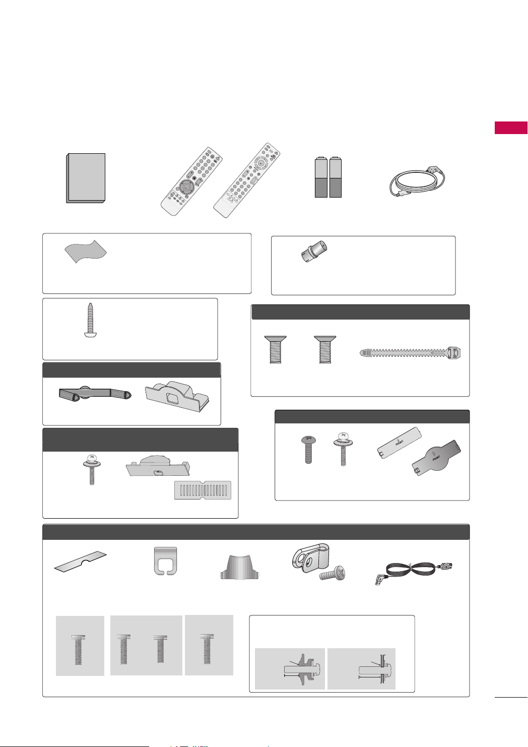
ACCESSORIES
Ensure that the following accessories are included with your TV. If an accessory is missing, please contact the
dealer where you purchased the TV.
The accessories included may differ from the images below.
or
PREPARATION
Owner’s Manual
Remote Control
* Wipe spots on the exterior only with
the polishing cloth.
* Do not wipe roughly when removing
Polishing Cloth
(Not included with all models.)
stain. Excessive pressure may cause
scratch or discoloration.
(Except 19/22LH20R,
47LH30FR, 47/55LH50YR,
19LU50R, 22LU50FR,
Screw for stand fixing
42/47LH70YR, 47LH90QR
)
(Refer to P.25)
FFoorr 1199//2222LLHH2200RR
Cable Management Clip Protection Cover
FFoorr 2266//3322//3377//4422LLHH2200RR,, 3322//3377//4422//4477LLHH3300FFRR,,
4422//4477//5555LLHH5500YYRR,, 4422//4477LLHH9900QQRR
(Except
55LH50YR)
x 4
Bolts for stand
assembly
(Refer to P.17)
or
Protection Cover
Batteries
(Some models)
You must connect it to the antenna
wire after fixing in Antenna Input.
RF Adapter
This adapter is For supplied in
(Some models)
FFoorr 1199LLUU5500RR,, 2222//2266LLUU5500FFRR
(For 26LU50FR)
(For 19LU50R, 22LU50FR)
x 3
x 2
Bolts for stand assembly
(Refer to P.19)
FF oorr 3322//4422LLFF2200FFRR
x 4
x 4
Bolts for stand assembly
(Refer to P.18)
Power Cord
AA rrggee nntt iinnaa
.
Cable Holder
(Refer to P.23)
or
Protection Cover
(Refer to
P
.18)
FFoorr
Protection cover
(Refer to P.20)
(For 32LH70YR)
32/42/47LH70YR
Cable management clip
(Refer to P.23)
(For 42LH70YR)
x 7
M4x20
x 3 x 4
M4x20 M4x16
bolts for stand assembly (Refer to P.20)
(For 42/47LH70YR)
Stand rear cover
(Refer to P.20)
(For 47LH70YR)
x 8
M4x16
Protective Bracket and
Screw for Power Cord
(Refer to P.23)
(For 42/47LH70YR)
Use screws 12mm(±0.5
(sold separately)
With guide spacer
12mm
USB Cable
) long on the TV assembly side.
Without guide spacer
12mm
9
Page 10

PREPARATION
INPUT
MENU
VOL
CH
ENTER
INPUT
MENU
ENTER
CH
VOL
O
N
O
F
F
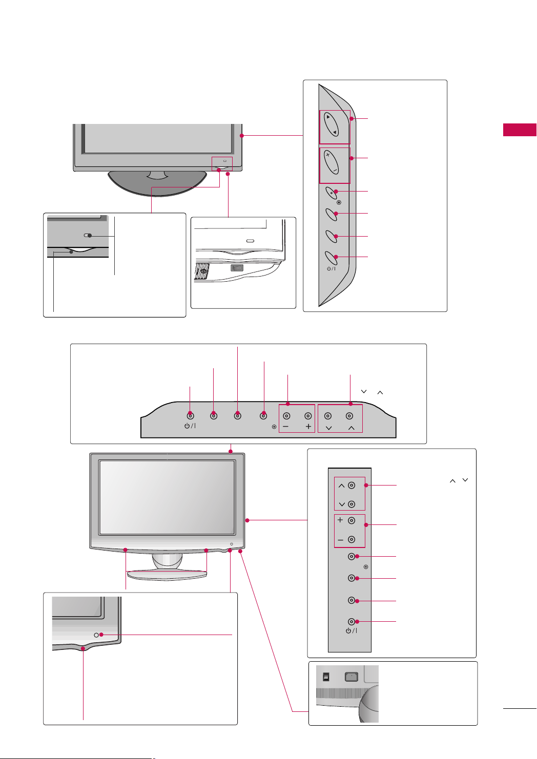
FRONT PANEL INFORMATION
■
Image shown may differ from your TV.
For 19/22/26/32/37/42LH20R, 32/37/42/47LH30FR
PREPARATION
19/22/26LH20R
INPUT Button
POWER Button
MENU Button
ENTER
Button
VOLUME
(-, +) Buttons
CHANNEL
EE,DD
(
) Buttons
32/37/42LH20R, 32/37/42/47LH30FR
CHANNEL
DD,EE
(
) Buttons
VOLUME (+, -)
Buttons
Remote Control Sensor,
Power/Standby Indicator
Illuminates red in standby mode.
Illuminates blue when the TV is switched on.
(Can be adjusted
menu.
pp..9922
GG
PPooww eerr IInnddiiccaattoorr
)
in the
For 32/42LF20FR
Power/Standby Indicator
Illuminates red in standby mode.
Illuminates blue when the TV is switched on.
Remote Control Sensor
POWER Button
OOPP TT II OO NN
ENTER Button
MENU Button
INPUT Button
POWER Button
AC power control switch
(Except 19/22LH20R)
CH
CHANNEL
Buttons
+
VOL
-
ENTER
VOLUME
Buttons
ENTER Button
MENU
MENU Button
INPUT
INPUT Button
10
Page 11
■
❖N❖N
❖❋❋❖❋❋
Image shown may differ from your TV.
For 42/47/55LH50YR
Remote Control
Sensor
Intelligent Sensor
Adjusts picture
according to the surrounding conditions.
Power/Standby Indicator
Illuminates red in standby mode.
Illuminates blue when the TV is switched on.
OFF ON
AC power control
switch
For 19LU50R, 22LU50FR, 26LU50FR
CH
VOL
ENTER
MENU
INPUT
CHANNEL
Buttons
PREPARATION
VOLUME
Buttons
ENTER Button
MENU Button
INPUT Button
POWER Button
19LU50R, 22LU50FR
INPUT Button
POWER Button
SPEAKER
Remote Control Sensor
INPUT
MENU Button
MENU
ENTER
ENTER Button
VOLUME
(-, +) Buttons
VOL
CH
26LU50FR
CH
VOL
ENTER
MENU
INPUT
CHANNEL
( , ) Buttons
CHANNEL ( , )
Buttons
VOLUME (+, -)
Buttons
ENTER Button
MENU Button
INPUT Button
POWER Button
Power/Standby Indicator
Illuminates red in standby mode.
Illuminates white when the TV is
switched on.
AC power control
switch
11
Page 12

PREPARATION
OFF ON
■
Image shown may differ from your TV.
For 32/42/47LH70YR
PREPARATION
Moving LED
POWER Button (Touch Sensor) ,
Power/Standby Indicator
Illuminates red in standby mode.
Illuminates white when the TV is
switched on.
For 42/47LH90QR
Remote Control Sensor,
Intelligent Sensor
Adjusts picture according
to the surrounding conditions.
AC power control switch
CH
VOL
ENTER
MENU
INPUT
CHANNEL
Buttons
VOLUME
Buttons
ENTER Button
MENU Button
INPUT Button
12
CH
CHANNEL ( , )
Buttons
VOL
VOLUME (+, -)
Buttons
ENTER
ENTER Button
MENU
MENU Button
SPEAKER
INPUT
INPUT Button
Remote Control Sensor,
Intelligent Sensor
POWER Button
Adjusts picture according to
the surrounding conditions
Power/Standby Indicator
Illuminates red in standby mode.
Illuminates white when the TV is switched on.
GG
PP oo wwee rr
pp..9922
)
AC power control switch
(Can be adjusted using the
IInn ddiiccaattoorr
in the OPTION menu.
CAUTION
When the TV cannot be turned on with the remote control, press the AC power control switch button on
GG
the TV.(The remote control will not work when the AC power control switch is switched off.)
Page 13

BACK PANEL INFORMATION
COMPONENT IN
AUDIO
VIDEO
L(L(MONO)MONO)
R
AUDIOAUDIO
AV
VIDEOVIDEO
IN
OUT
VARIABLE AUDIO OUTVARIABLE AUDIO OUT
HDMI/DVI IN
RGB IN
(PC)
RS-232C IN
(CONTROL)
AUDIO IN
(RGB/DVI)
USB IN
SERVICE ONLY
ANTENNA IN
L( MONO)
R
AUDIO
VIDEO
VARIABLE AUDIO OUT
COMPONENT IN
AUDIO
VIDEO
L(L(MONO)MONO)
R
AUDIOAUDIO
AV
VIDEOVIDEO
IN
OUT
VARIABLE AUDIO OUTVARIABLE AUDIO OUT
HDMI
/DVI IN
RGB IN
(PC)
RS-232C IN
(CONTROL)
AUDIO IN
(RGB/DVI)
USB IN
SERVICE ONLY
HDMI
1
2
ANTENNA
IN
COMPONENT IN
AUDIO
VIDEO
L(L(MONO)MONO)
R
AUDIOAUDIO
AV
VIDEOVIDEO
IN 1
OUT
VARIABLE AUDIO OUTVARIABLE AUDIO OUT
/DVI IN
RGB IN
(PC)
RS-232C IN
(CONTROL)
AUDIO IN
(RGB/DVI)
USB IN
SERVICE ONLY
ANTENNA
IN
1
AV IN2
IN 2
■
Image shown may differ from your TV.
For 19/22LH20R
2 3 8
For 26/32/37/42LH20R
2 3
PREPARATION
4
5 6 7
8
4
5 6 7
For 32/42LF20FR
2
5 6 7
3
8
2
4
6
13
Page 14

PREPARATION
VARIABLE AUDIO OUT
MONO)
AUDIO
VIDEO
COMPONENT IN
AUDIO
VIDEO
RGB IN
(PC)
RS-232C IN
(CONTROL)
AUDIO IN
(RGB/DVI)
USB IN
SERVICE ONLY
ANTENNA
IN
HDMI/DVI IN
2
1(DVI)
AV O UT
VARIABLE AUDIO OUTVARIABLE AUDIO OUT
AV IN
L(L(MONO)MONO)
R
AUDIOAUDIO
VIDEOVIDEO
VARIABLE AUDIO OUT
L(MONO)
R
AUDIO
VIDEO
COMPONENT IN
AUDIO
VIDEO
RGB IN
(PC)
RS-232C IN
(CONTROL)
AUDIO IN
(RGB/DVI)
USB IN
SERVICE ONLY
HDMI/DVI IN
2
1(DVI)
ANTENNA
IN
AV OUT
VARIABLE AUDIO OUTVARIABLE AUDIO OUT
AV IN 1
L(L(MONO)MONO)
R
AUDIOAUDIO
VIDEOVIDEO
AV IN2
IN 3
AV IN2
IN 3
■
Image shown may differ from your TV.
For 32/37/42/47LH30FR
PREPARATION
2 3
RS-232C IN
(CONTROL)
2
RGB IN
1
/DVI IN
VIDEO
COMPONENT IN
5 6 7
For 19LU50R, 22LU50FR
2 3
AUDIO
(PC)
1
AUDIO IN
(RGB/DVI)
VIDEO
8
4
R
AUDIO
L(L(MONO)
VARIABLE AUDIO OUT
AV OUT
AV IN 1
ANTENNA
4
8
2
6
IN
14
For 26LU50FR
5
32
5
8
6 7
2
4
6
76
Page 15

1
2
AUDIO IN
(RGB/DVI)
RGB IN
(PC)
RGB IN
COMPONENT IN
AUDIO
VIDEO
L/L/ MONOMONO
R
AUDIOAUDIO
VIDEOVIDEO
AV IN 1
RS-232C IN
(CONTROL)
ANTENNA IN
AV OUT
VARIABLE AUDIO OUT
AV IN 2
/DVI IN
1(DVI)
2
3
■
Image shown may differ from your TV.
For 32/42/47LH70YR
8
2
5
1
Power Cord Socket
For operation with AC power.
Caution: Never attempt to operate the TV on DC
power.
2
HDMI/DVI IN, HDMI IN
Digital Connection.
Supports HD video and Digital audio. Doesn’t
support 480i/576i.
Accepts DVI video using an adapter or HDMI to
DVI cable (not included).
3
RS-232C IN (CONTROL) PORT
Used by third party devices.
4
RGB IN
RGB IN(PC)
Analog PC Connection. Uses a D-sub 15 pin cable
(VGA cable).
AUDIO IN (RGB/DVI)
1/8" (0.32 cm) headphone jack for analog PC audio input.
5
COMPONENT IN
Analog Connection.
Supports HD.
Uses a red, green, and blue cable for video & red
and white for audio.
4 736
1
AV (Audio/Video) IN
6
Analog composite connection. Supports standard
definition video only (480i).
AV Output
Connect second TV or monitor to the AV OUT
socket on the TV.
Variable Audio Output
Connect an external amplifier or add a subwoofer
to your surround sound system.
ANTENNA IN
7
Connect over-the air signals to this jack.
Connect cable signals to this jack.
8
USB IN
(For 32/37/42/47LH30FR, 32/42/47LH70YR
Used for viewing photos/movies and listening to
MP3.
USB IN SERVICE ONLY
19/22/26/32/37/42LH20R, 32/42LF20FR, 19LU50R,
(For
22/26LU50FR)
Used for software updates.
PREPARATION
)
15
Page 16
PREPARATION
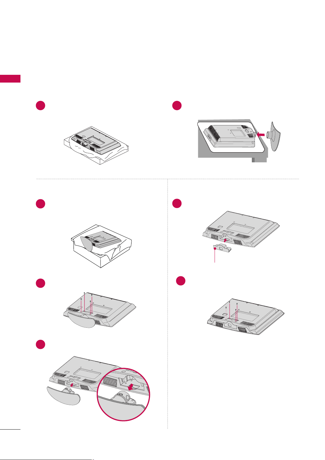
STAND INSTRUCTION
■
Image shown may differ from your TV.
For 19/22LH20R
PREPARATION
INSTALLATION
Carefully place the TV screen side down on a
1 2
cushioned surface to protect the screen from
damage.
DETACHMENT
Carefully place the TV screen side down on a
1
cushioned surface to protect the screen from
damage.
Loose the bolts from the TV.
2
Assemble the TV as shown until you hear it click.
PROTECTION COVER
Insert the
4
Fix the 4 bolts securely using the holes in the
5
back of the TV.
PPRROOTTEECCTTIIOONN CCOO VV EERR
PPRR OOTTEE CCTT IIOONN CCOOVVEERR
into the TV.
16
Detach the stand from the TV.
3
Page 17

For 26/32/37/42LH20R, 32/37/42/47LH30FR, 42/47LH50YR, 42/47LH90QR
!
INSTALLATION
Carefully place the TV screen side down on a
1
cushioned surface to protect the screen from
damage.
Assemble the TV as shown.
2
Fix the 4 bolts securely using the holes in the
3
back of the TV.
DETACHMENT
Carefully place the TV screen side down on a
1
cushioned surface to protect the screen from
damage.
Loose the bolts from the TV.
2
Detach the stand from the TV.
3
PREPARATION
NOTE
When assembling the desk type stand, make sure
GG
the bolt is fully tightened (If not tightened fully,
the TV can tilt forward after the product installation). Do not over tighten.
PROTECTION COVER
For 26/32/37/42LH20R,
32/37/42/47LH30FR, 42/47/55LH50YR
After removing the stand, install the included
pprrootteecc ttii oonn ccoovv eerr
Press the
until you hear it click.
PPRROOTTEECCTTIIOONN CCOOVVEERR
For 42/47LH90QR
Insert the
After removing the protection paper from the
protection cover, adhere it to the TV as shown.
PPRROOTTEECCTTIIOONN CCOO VV EERR
over the hole for the stand.
into the TV
into the TV.
17
Page 18

PREPARATION
For 32/42LF20FR
PREPARATION
INSTALLATION
Carefully place the TV screen side down on a
1
cushioned surface to protect the screen from
damage.
Assemble the
2
BBAASS EE
Assemble the TV as shown.
3
SSTTAANNDD BBOODDYY
with the included screws.
SSTTAANNDD BBOODDYY
SSTTAANNDD
to the
CCOOVVEERR BBAASS EE
DETACHMENT
Carefully place the TV screen side down on a
1
cushioned surface to protect the screen from
damage.
Loose the bolts from the TV.
2
Detach the stand from the TV.
3
18
Fix the 4 bolts securely using the holes in the
4
back of the TV.
PROTECTION COVER
After removing the stand, install the included
pprrootteecc ttii oonn ccoovveerr
stand.
Press the
until you hear it click.
PPRROOTTEECCTTIIOONN CCOOVVEERR
over the hole for the
into the TV
Page 19
19" 22" 26"
!
19" 22" 26"
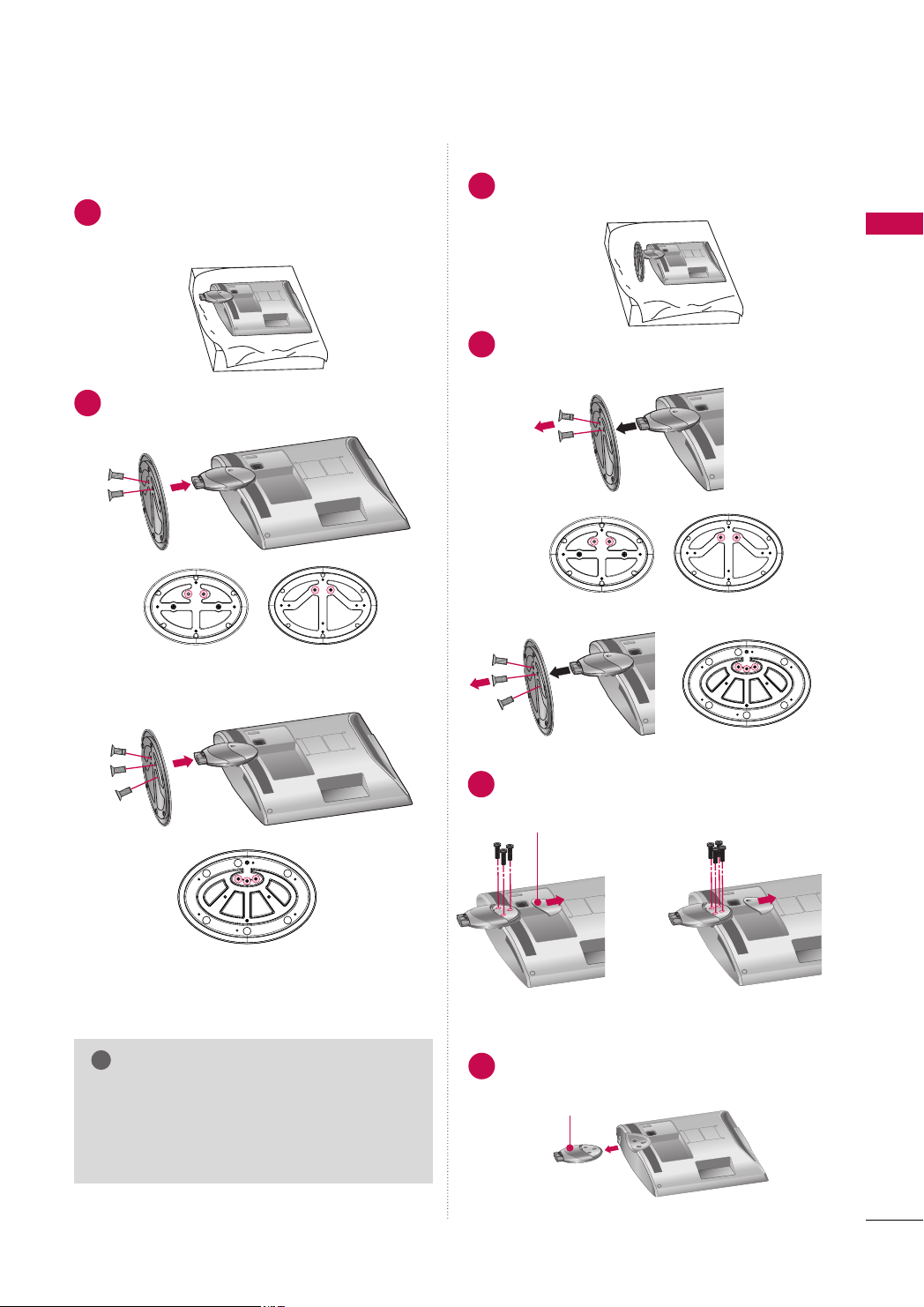
For 19LU50R, 22/26LU50FR
INSTALLATION
Carefully place the TV screen side down on a
1
cushioned surface to protect the screen from
damage.
Fix the bolts securely using the holes.
2
19LU50R, 22LU50FR
DETACHMENT
Carefully place the TV screen side down on a
1
cushioned surface to protect the screen from
damage.
Loose the bolts and then detach the stand
2
from the TV.
19LU50R, 22LU50FR
26LU50FR
PREPARATION
26LU50FR
NOTE
When assembling the desk type stand, make sure
GG
the bolt is fully tightened (If not tightened fully,
the TV can tilt forward after the product installation). Do not over tighten.
Loose the bolts from the TV.
3
And detach the
CCOOVVEERR BBAASS EE
19LU50R, 22LU50FR 26LU50FR
Detach the
4
SSTTAANNDD BBOODDYY
CCOOVVEERR BB AASSEE
SSTTAANNDD BBOODDYY
from the TV.
from the TV.
19
Page 20
PREPARATION
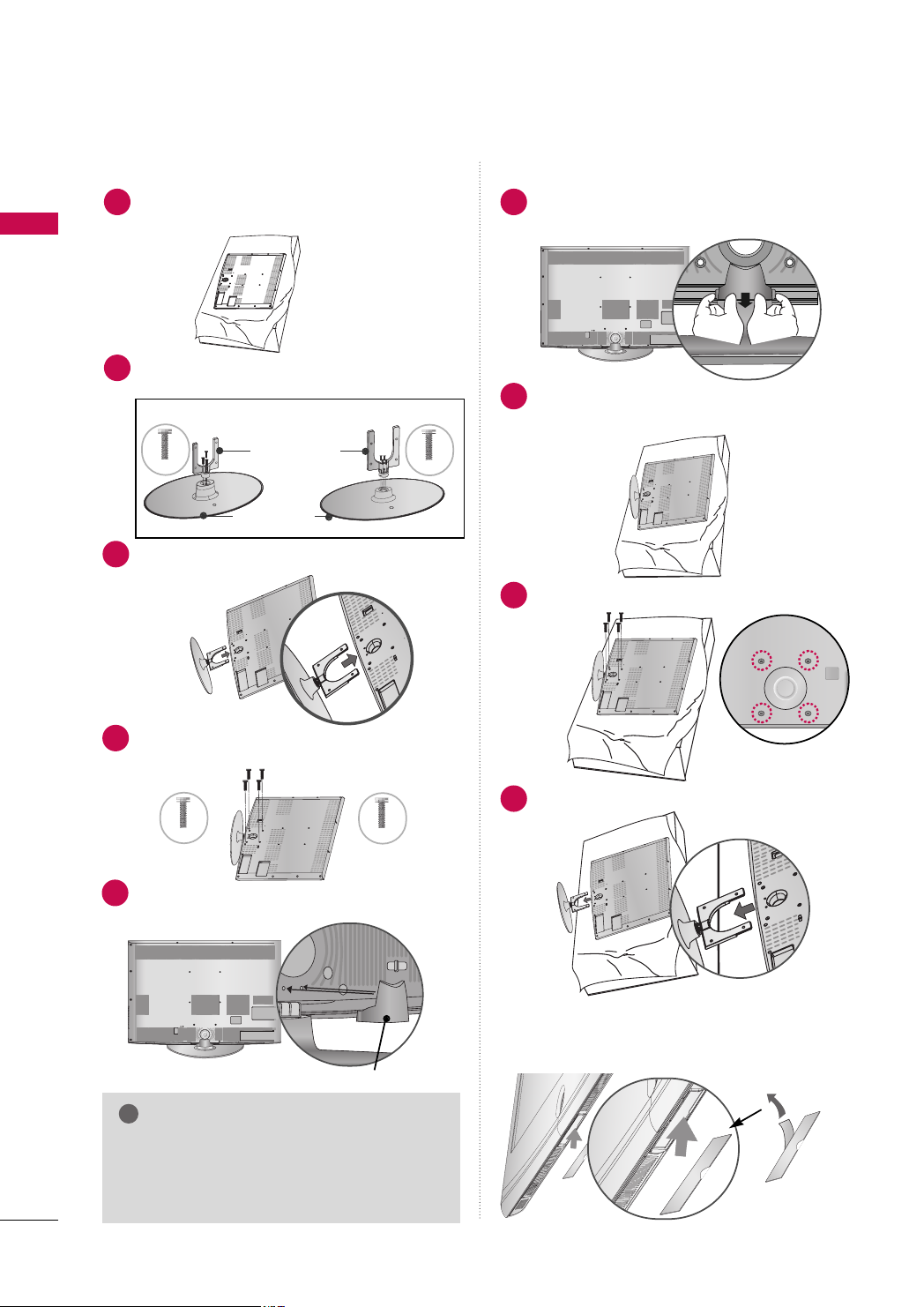
!
For 32/42/47LH70YR
■
Image shown may differ from your TV.
INSTALLATION
Carefully place the TV screen side down on a cush-
1
ioned surface to protect the screen from damage.
PREPARATION
DETACHMENT
Detach the
1
Grip the knob in your fingers and pull it.
SSTTAANNDD RREEAARR CCOOVVEERR
as shown.
Assemble the
2
BBAASS EE
32LH70YR, 42LH70YR
M4x20
Assemble the TV as shown.
3
Fix the 4 bolts securely using the holes in the
4
back of the TV.
32LH70YR
M4x20
SSTTAANNDD BBOODDYY
with the included screws.
Stand Body
Stand Base
to the
42/47LH70YR
SSTTAANNDD
47LH70YR
M4x16
M4x16
Carefully place the TV screen side down on a
2
cushioned surface to protect the screen from
damage.
Loose the bolts from the TV.
3
Detach the stand from the TV.
4
Install the
5
(For 42/47LH70YR)
SSTTAANNDD RREEAARR CCOOVVEERR
as shown.
PROTECTIVE COVER
After removing the protection paper from the
SSTTAA NNDD RR EE AARR CCOOVVEERR
NOTE
When assembling the desk type stand, make sure
GG
the bolt is fully tightened (If not tightened fully,
the TV can tilt forward after the product installation). Do not over tighten.
20
protection cover, adhere it to the TV as shown.
Page 21
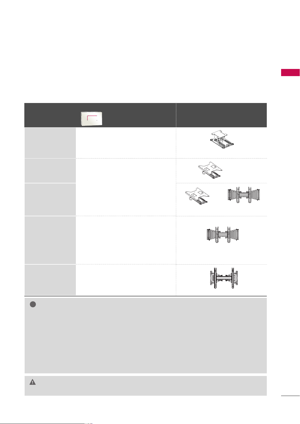
VESA WALL MOUNTING
!
AA
BB
Install your wall mount on a solid wall perpendicular to the floor. When attaching to other building materials, please
contact your nearest installer.
If installed on a ceiling or slanted wall, it may fall and result in severe personal injury.
We recommend that you use an LG brand wall mount when mounting the TV to a wall.
LG recommends that wall mounting be performed by a qualified professional installer.
For 32/42/47LH70YR: First you connect the USB extension cable to the USB IN terminal, and then hang it on the wall.
VESA (A *B)
Model
Standard Screw Quantity
Wall Mount Bracket (sold separately)
PREPARATION
19/22LH20R,
19LU50R, 22LU50FR
10 0* 10 0 M 4 4
26LH20R, 26LU50FR
200* 10 0 M 4 4
32LH20R, 32LF20FR,
32LH30FR, 32LH70YR
37/42LH20R,
42LF20FR,
37/42/47LH30FR
42/47LH50YR,
200* 200 M6 4
42/47LH70YR,
42/47LH90QR
55LH50YR
400* 400 M6 4
NOTE
Screw length needed depends on the wall mount
GG
used. For further information, refer to the instructions
included with the mount.
Standard dimensions for wall mount kits are shown in
GG
the table.
When purchasing our wall mount kit, a detailed instal-
GG
lation manual and all parts necessary for assembly are
provided.
Do not use screws longer then the standard dimension,
GG
as they may cause damage to the inside to the TV.
RW120
RW230
RW230
AW-47LG30M
AW-47LG30M
AW-55LH40M
For wall mounts that do not comply with the VESA
GG
standard screw specifications, the length of the screws
may differ depending on their specifications.
Do not use screws that do not comply with the VESA
GG
standard screw specifications.
Do not fasten the screws too tightly, this may damage
the TV or cause the TV to a fall, leading to personal
injury. LG is not liable for these kinds of accidents.
LG is not liable for TV damage or personal injury when
GG
a non-VESA or non specified wall mount is used or the
consumer fails to follow the TV installation instructions.
Do not install your Wall Mount Bracket while your TV is turned on. It may result in per-
CAUTION
GG
sonal injury due to electric shock.
21
Page 22
PREPARATION
!
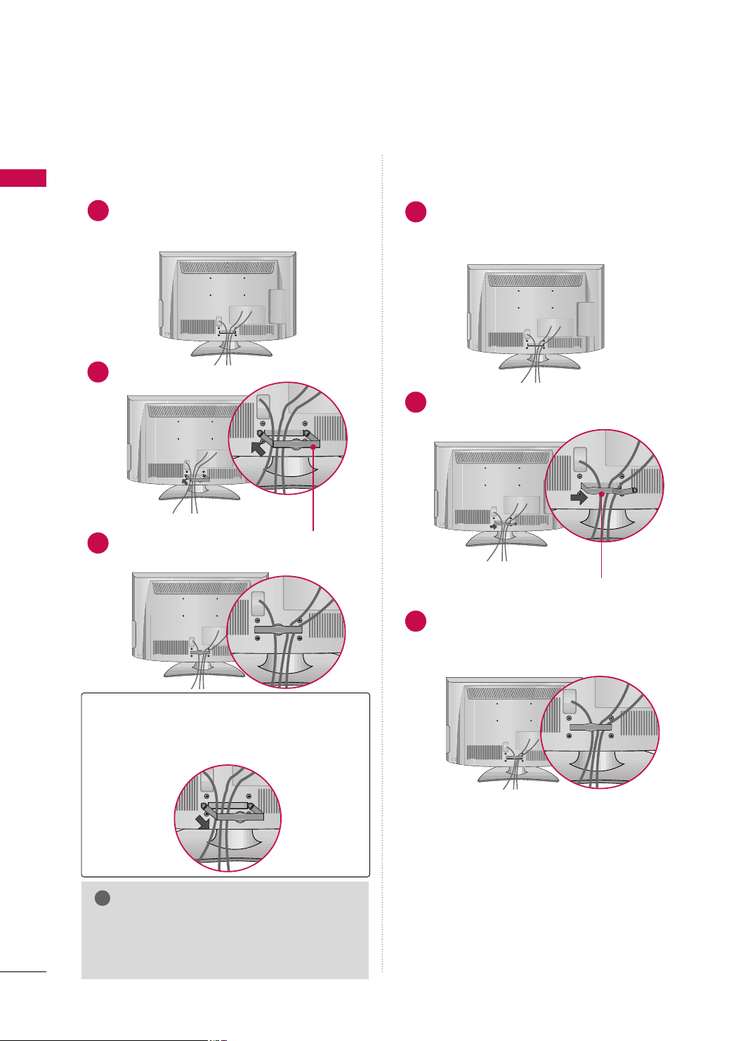
CABLE ARRANGEMENT
■
Image shown may differ from your TV.
PREPARATION
For 19/22LH20R
Connect the cables as necessary.
1
To connect additional equipment, see the
EXTERNAL EQUIPMENT SETUP section.
Install the CABLE MANAGEMENT CLIP as shown.
2
For 26/32/37/42LH20R, 32/42LF20FR,
32/37/42/47LH30FR, 42/47/55LH50YR, 42/47LH90QR
Connect the cables as necessary.
1
To connect additional equipment, see the
EXTERNAL EQUIPMENT SETUP section.
Install the CABLE MANAGEMENT CLIP as
2
shown.
CC AABB LLEE MMAANNAA GGEE MMEE NNTT CCLL II PP
Put the cables inside the CABLE MANAGEMENT
3
CLIP and snap it closed.
How to remove the CABLE MANAGEMENT CLIP
Hold the CABLE MANAGEMENT CLIP with both
GG
hands and pull it backward.
NOTE
Do not hold the CABLE MANAGEMENT CLIP
GG
when moving the TV.
- If the TV is dropped, you may be injured or the
product may be broken.
CC AABB LLEE MMAANNAA GGEE MMEE NNTT CCLL II PP
Put the cables inside the CABLE MANAGEMENT
3
CLIP and snap it closed.
22
Page 23

For 19LU50R, 22/26LU50FR
After connecting the cables as necessary,
1
install CABLE HOLDER as shown and bundle
the cables.
For 32/42/47LH70YR
PREPARATION
Align the hole with the tab on the
1
MMAANNAAGG EEMMEENN TT CCLLIIPP
Turn the
shown.
Note: This cable management clip can be broken by excessive pressure.
Connect the cables as necessary.
2
To connect additional equipment, see the
EXTERNAL EQUIPMENT SETUP section.
CCAABBLL EE MMAANNAAGGEEMMEENNTT CC LLIIPP
.
CCAABBLLEE
as
HOW TO SECURE THE POWER CABLE
SSCCRR EE WW
Secure the power cable with the
BBRRAACCKKEETT
vent the power cable from being removed by accident.
and the bolt as shown. It will help pre-
PPRROOTTEECC TTIIVVEE
PPRR OOTTEE CCTT IIVV EE BBRR AACC KKEE TT
23
Page 24

PREPARATION
12
0
3
0
!
DESKTOP PEDESTAL INSTALLATION
■
Image shown may differ from your TV.
PREPARATION
For proper ventilation, allow a clearance of 4 inches on all four sides from the wall.
4 inches
4 inches
CAUTION
4 inches
Ensure adequate ventilation by following the clearance recommendations.
GG
Do not mount near or above any type of heat source.
GG
4 inches
SWIVEL STAND (Except 19/22LH20R, 19LU50R, 22/26LU50FR)
After installing the TV, you can adjust the TV manually to the left or right direction by 20 degrees to suit your
viewing position.
POSITIONING YOUR DISPLAY (For 19/22LH20R)
■
Here shown may be somewhat different from your TV.
■
Adjust the position of the panel in various ways for maximum comfort.
• Tilt range
NOTE
may damage the TV.
19LU50R, 22/26LU50FR have a fixed stand type without the tilt and swivel features so excessive pressure
GG
24
Page 25

ATTACHING THE TV TO A DESK
(Except 19/22LH20R, 47LH30FR, 47/55LH50YR, 19LU50R, 22LU50FR, 42/47LH70YR, 47LH90QR)
The TV must be attached to a desk so it cannot be pulled in a forward/backward direction, potentially causing
injury or damaging the product.
Stand
1-Screw
(provided as parts of the product)
Desk
Stand
1-Screw
(provided as parts of the product)
Desk
Stand
PREPARATION
1-Screw
(provided as parts of the product)
Desk
WARNING
To prevent TV from falling over, the TV should be securely attached to the floor/wall per installation
GG
instructions. Tipping, shaking, or rocking the machine may cause injury.
KENSINGTON SECURITY SYSTEM
■
This feature is not available for all models.
- The TV is equipped with a Kensington Security System connector on
the back panel. Connect the Kensington Security System cable as
shown below.
- For the detailed installation and use of the Kensington Security
System, refer to the user’s guide provided with the Kensington
Security System.
For further information, contact
the internet homepage of the Kensington company. Kensington sells
security systems for expensive electronic equipment such as notebook PCs and LCD projectors.
NOTE: The Kensington Security System is an optional accessory.
hh tttt pp::////wwwwww..kk eennss iinnggttoonn ..ccoomm
,
25
Page 26

PREPARATION
!
SECURING THE TV TO THE WALL TO PREVENT FALLING
WHEN THE TV IS USED ON A STAND
■
PREPARATION
You should purchase necessary components to prevent the TV from tipping over (when not using a wall mount).
■
Image shown may differ from your TV.
We recommend that you set up the TV close to a wall so it cannot fall over if pushed backwards.
Additionally, we recommend that the TV be attached to a wall so it cannot be pulled in a forward direction,
potentially causing injury or damaging the product.
Caution: Please make sure that children don’t climb on or hang from the TV.
■
Insert the eye-bolts (or TV brackets and bolts) to tighten the product to the wall as shown in the picture.
*If your product has the bolts in the eye-bolts position before inserting the eye-bolts, loosen the bolts.
* Insert the eye-bolts or TV brackets/bolts and tighten them securely in the upper holes.
Secure the wall brackets with the bolts (sold separately) to the wall. Match the height of the bracket that is
mounted on the wall to the holes in the product.
Ensure the eye-bolts or brackets are tightened securely.
■
Use a sturdy rope (sold separately) to tie the product. It is safer to tie
the rope so it becomes horizontal between the wall and the product.
NOTE
Use a platform or cabinet strong enough and large enough to support the size and weight of the TV.
GG
To use the TV safely, make sure that the height of the bracket on the wall and the one on the TV are
GG
the same.
26
Page 27

■
ANTENNAANTENNA
IN IN
ANTENNA
IN
To prevent damage do not connect to the power outlet until all connections are made between the devices.
■
Image shown may differ from your TV.
ANTENNA OR CABLE CONNECTION
1. Antenna (Analog)
Wall Antenna Socket or Outdoor Antenna without a Cable Box
Connection.
For optimum picture quality, adjust antenna direction if needed.
Wall
Multi-family Dwellings/Apartments
(Connect to wall antenna socket)
Antenna
Socket
Outdoor
RF Coaxial Wire (75 ohm)
Antenna
(VHF, UHF)
Single-family Dwellings /Houses
(Connect to wall jack for outdoor
antenna)
2. Cable
Cable TV
Wall Jack
RF Coaxial Wire (75 ohm)
ANTENNA
IN
Copper Wire
Be careful not to bend the copper wire
when connecting the antenna.
PREPARATION
■
To improve the picture quality in a poor signal area, please purchase a signal amplifier and install properly.
■
If the antenna needs to be split for two TV’s, install a 2-Way Signal Splitter.
■
If the antenna is not installed properly, contact your dealer for assistance.
27
Page 28

EXTERNAL EQUIPMENT SETUP
L(MONO
VIDEO
1
2
HDMI
/DVI IN
HDMI
RS-232C IN
(CONTROL)
RGB IN (PC)
USB IN
SERVICE ONLY
AUDIO IN
(RGB/DVI
AUDIOAUDIO
VIDEOVIDEO
VAR IABLE A
Y L RPBP
R
COMPONENT IN
■
To prevent the equipment damage, never plug in any power cords until you have finished connecting all equipment.
■
This part of EXTERNAL EQUIPMENT SETUP mainly use picture for
HD RECEIVER SETUP
Component Connection
1. How to connect
)
EXTERNAL EQUIPMENT SETUP
Connect the video outputs (Y, P
1
top box to the
CCOOMMPPOONNEENNTT IINN VVIIDDEEOO
PPOONNEENNTT IINN VVIIDDEEOO 11*/22
the jack colors (Y = green, P
Connect the audio output of the digital set-top box to the
2
CCOOMMPPOONNEENNTT IINN AAUUDDIIOO
AAUUDDIIOO 11*/22
CCOOMMPPOONNEENNTT IINN VVIIDDEEOO/AAUUDDIIOO
*
* jacks on the TV.
: For 19/22/26/32/37/42LH20R, 32/42LF20FR,
32/37/42/47LH30FR, 19LU50R, 22/26LU50FR
CCOOMMPPOONNEENNTT IINN VVIIDD EEOO 11/AAUUDDIIOO 11
*
CCOOMMPPOONNEENNTT IINN VVIIDD EEOO 22/AAUUDDIIOO 22
: For 32/42/47LH70YR
B, PR
of the digital set-
CCOO MM--
* or
* jacks on the TV. Match
B = blue, and PR = red).
CCOOMMPPOONNEENNTT IINN
* or
,
22 66// 3322//3377//4422 LLHH2200 RR
1
.
2
2. How to use
■
■
CCoo mmpp oonneenntt
*
CCoo mmpp oonn eenn tt11/22
*
Supported Resolutions
Signal
480i
480p
720 p
10 8 0 i
10 8 0 p
Turn on the digital set-top box.
(
Refer to the owner’s manual for the digital set-top box operation.
Select the
CCoo mmpp oonneenntt
source on the TV using the
CCoo mmpp oonn eenn tt11*/22
*or
IINN PPUU TT
button on the remote
* input
control.
: For 19/22/26/32/37/42LH20R,
Y, CB/PB, CR/PR
32/42LF20FR, 32/37/42/47LH30FR,
19LU50R, 22/26LU50FR
: For 32/42/47LH70YR
Yes (50/60Hz only)
Component
Yes
Yes
Yes
Yes
Yes (24/30/50/60Hz)
HDMI
No
Yes
Yes
Yes
1920x1080p
)
Resolution
720x480i
720x480p
720x576i
720x576p
1280x720p
1920x1080i
Horizontal Vertical
Frequency(KHz)Frequency(Hz
15.73 59.94
15.75 60.00
31.47 59.94
31.50 60.00
15.625 50.00
31.25 50.00
44.96 59.94
45.00 60.00
37.50 50.00
28.125 50.00
33.72 59.94
33.75 60.00
56.25 50.00
67.432 59.94
67.50 60.00
)
28
Page 29

HDMI Connection
HDMI
/DVI IN
HDMI
/DVI IN
HDMI HDMI
(CONTROL)
RGB IN (PC)
COMPONENT IN
AUDIOAUDIO
VIDEOVIDEO
11
22
HDMI OUTPUT
!
1. How to connect
Connect the digital set-top box to the
1
HHDDMMII//DDVVII IINN 11
22
HHDDMMII IINN 22*/33
* or
No separate audio connection is necessary.
2
HHDDMMII//DDVVII IINN 11((DDVVII))
* or
* jack on the TV.
HDMI supports both audio and video.
HHDDMMII//DDVVII IINN
*
HHDDMMII//DDVVII IINN 11,HHDDMMII 22
*
: For 19/22LH20R
: For 26/32/37/42LH20R,
32/37/42/47LH30FR, 19LU50R,
22/26LU50FR
HHDDMMII//DDVVII IINN 11,HHDDMMII IINN 22
*
HHDDMMII IINN 33
*
HHDDMMII//DDVVII IINN 11((DDVVII)), HHDDMMII IINN 22/33
*
: For 32/37/42/47LH30FR, 26LU50FR
2. How to use
■
Turn on the digital set-top box.
(
Refer to the owner’s manual for the digital set-top box.
■
Select the
TV using the
HHDDMMII
*
HHDDMMII11/22
*
HHDDMMII33
*
NOTE
Check HDMI cable over version 1.3.
GG
If the HDMI cables don’t support HDMI version
1.3, it can cause flickers or no screen display. In
this case use the latest cables that support
HDMI version 1.3.
HDMI mode supports PCM audio format only.
GG
If the Audio setting is set to Dolby/DTS/Bitstream
GG
in some DVDP/STB, make sure to change the setting to PCM.
HHDDMMII
HHDDMMII11*/22*/33
*or
IINNPPUUTT
button on the remote control.
: For 19/22LH20R
: For 26/32/37/42LH20R, 32/42LF20FR
32/37/42/47LH30FR, 19LU50R, 22/26LU50FR,
32/42/47LH70YR
: For 32/37/42/47LH30FR, 26LU50FR,
32/42/47LH70YR
HHDDMMII//DDVVII IINN
: For 32/42LF20FR
: For 32/42/47LH70YR
* input source on the
*,
HHDDMMII
*,
)
HDMI-DTV mode
Resolution
720x480
720x576
1280x720
1920x1080i
1920x1080p
1
Horizontal Vertical
Frequency(kHz) Frequency(Hz)
31.47 59.94
31.50 60.00
31.25 50.00
44.96 59.94
45.00 60.00
37.50 50.00
33.72 59.94
33.75 60.00
28.125 50.00
67.432 59 .94
67.50 60.00
56.25 50.00
27.00 24.00
33.75 30.00
EXTERNAL EQUIPMENT SETUP
29
Page 30

EXTERNAL EQUIPMENT SETUP
L R
DVI OUTPUT
AUDIO
L(MONO)
VIDEO
HDMI
/DVI IN
HDMI
/DVI IN
HDMI HDMI
RS-232C IN
(CONTROL)
RGB IN (PC)
USB IN
SERVICE ONLY
A
AV
COMPONENT IN
AUDIOAUDIO
VIDEOVIDEO
VARIABLE AUD
11
22
AUDIO IN
(RGB/DVI)
AUDIO IN
(RGB/DVI)
!
DVI to HDMI Connection
1. How to connect
EXTERNAL EQUIPMENT SETUP
Connect the DVI output of the digital set-top box to the
1
HHDDMMII//DDVVII IINN
IINN 11((DDVVII ))
Connect the digital set-top box audio output to the
2
AAUUDDIIOO II NN ((RRGGBB// DD VVII))
HHDDMMII//DDVVII IINN
*
HHDDMMII// DDVVII IINN 11
*
HHDDMMII//DDVVII IINN 11
*,
*, or
* jack on the TV.
jack on the TV.
: For 19/22LH20R
: For 26/32/37/42LH20R, 32/42LF20FR,
32/37/42/47LH30FR, 19LU50R,
22/26LU50FR
HHDDMMII//DDVVII IINN 11((DDVVII ))
*
: For 32/42/47LH70YR
HHDDMMII//DDVVII
1
2
2. How to use
■
■
*
*
Turn on the digital set-top box.
(
Refer to the owner’s manual for the digital set-top box.
Select the
using the
HHDDMMII
: For 19/22LH20R
HHDDMMII 11
: For 26/32/37/42LH20R, 32/42LF20FR,
HHDDMMII
IINNPPUUTT
HHDDMMII11
*, or
* input source on the TV
button on the remote control.
32/37/42/47LH30FR, 32/42/47LH70YR,
19LU50R, 22/26LU50FR
NOTE
A DVI to HDMI cable or adapter is required for this
GG
connection. DVI doesn't support audio, so a separate
audio connection is necessary.
HDMI mode supports PCM audio format only.
GG
If the Audio setting is set to Dolby/DTS/Bitstream in
GG
some DVDP/STB, make sure to change the setting to
PCM.
)
30
Page 31

DVD SETUP
L(MONO
VIDEO
1
2
HDMI
/DVI IN
HDMI
RS-232C IN
(CONTROL)
RGB IN (PC)
USB IN
SERVICE ONLY
AUDIO IN
(RGB/DV
AUDIOAUDIO
VIDEOVIDEO
VAR IABLE
Y L RPBP
R
COMPONENT IN
Component Connection
1. How to connect
)
Connect the video outputs (Y, P B, PR
1
PPOONNEENNTT IINN VVIIDDEEOO
11*/22
* jacks on the TV. Match the jack colors (Y = green, P
blue, and P
Connect the audio outputs of the DVD to the
2
R = red
NN EE NNTT IINN AAUUDD IIOO
* or
)
.
CCOOMMPPOONNEENNTT IINN AAUUDDIIOO 11
* or
of the DVD to the
CCOOMMPPOONNEENNTT IINN VVIIDDEEOO
/22* jacks on the TV.
CCOOMMPPOONNEENNTT IINN VVIIDDEEOO/AAUUDDIIOO
*
: For 19/22/26/32/37/42LH20R, 32/42LF20FR,
32/37/42/47LH30FR, 19LU50R, 22/26LU50FR
CCOOMMPPOONNEENNTT IINN VVIIDDEEOO 11/AAUUDDIIOO 11
*
,
CCOOMMPPOONNEENNTT IINN VVIIDD EEOO 22/AAUUDDIIOO 22
: For 32/42/47LH70YR
2. How to use
■
Turn on the DVD player, insert a DVD.
■
Select the
on the TV using the
■
Refer to the DVD player's manual for operating instructions.
CCoo mmpp oonneenntt
*
CCoo mmpp oonn eenn tt11/22
*
CCoommppoonneenntt
CCoommppoonneenntt11*/22
* or
IINNPPUUTT
button on the remote control.
: For 19/22/26/32/37/42LH20R, 32/42LF20FR,
32/37/42/47LH30FR, 19LU50R, 22/26LU50FR
: For 32/42/47LH70YR
CCOOMM--
CCOO MMPPOO--
* input source
B =
EXTERNAL EQUIPMENT SETUP
*
1
2
Component Input ports
To get better picture quality, connect a DVD player to the component input ports as shown below.
R-Y
R
R
P
Cr
Pr
Component ports on the TV
Video output ports
on DVD player
YPBP
B
Y
Y
Y
Y
P
B-Y
Cb
Pb
31
Page 32

EXTERNAL EQUIPMENT SETUP
VID
HDMI
/DVI IN
HDMI
/DVI IN
HDMI HDMI
RS-232C IN
(CONTROL)
RGB IN (PC)
U
SERV
COMPONENT IN
AUDIOAUDIO
VIDEOVIDEO
11
22
HDMI OUTPUT
!
L R
VIDEO
AUDIO
RS-232C IN
(CONTROL)
RGB IN (PC)
USB IN
SERVICE ONLY
AUDIO IN
(RGB/DVI)
ANTENNA
IN
AVAV
AUDIOAUDIO
L(MONO)L(MONO)
VIDEOVIDEO
ININ
RR
AUDIOAUDIO
V
ARIABLE AUDIO OUT
V
ARIABLE AUDIO OUT
OUT
Composite (RCA) Connection
1. How to connect
EXTERNAL EQUIPMENT SETUP
Connect the
1
DVD. Match the jack colors (Video = yellow, Audio Left
AAUUDDIIOO/VVIIDDEEOO
jacks between TV and
= white, and Audio Right = red).
2. How to use
■
Turn on the DVD player, insert a DVD.
■
Select the
the
■
Refer to the DVD player's manual for operating instructions.
AAVV
*
: For 19/22/26/32/37/42LH20R, 19LU50R, 22LU50FR
AAVV11/22
*
AAVV
AAVV11*/22
IINN PPUU TT
* or
button on the remote control.
* input source on the TV using
: For 32/42LF20FR, 32/37/42/47LH30FR,
26LU50FR, 32/42/47LH70YR
HDMI Connection
1. How to connect
Connect the HDMI output of the DVD to the
1
HHDDMMII//DDVVII IINN*,HHDDMMII//DDVVII IINN 11
11((DDVVII))
No separated audio connection is necessary.
2
HHDDMMII 22
*,
HHDDMMII IINN 22*/33
* or
HDMI supports both audio and video.
HHDDMMII//DDVVII IINN
*,
* jack on the TV.
1
1
32
HHDDMMII//DDVVII IINN
*
HHDDMMII//DDVVII IINN 11,HHDDMMII 22
*
HHDDMMII//DDVVII IINN 11,HHDDMMII IINN 22
*
HHDDMMII IINN 33
*
HHDDMMII//DDVVII IINN 11((DDVVII)), HHDDMMII IINN 22/33
*
2. How to use
■
Select the
the TV using the
■
Refer to the DVD player's manual for operating instructions.
HHDDMMII
*
HHDDMMII11/22
*
HHDDMMII33
*
: For 19/22LH20R
: For 26/32/37/42LH20R,
32/37/42/47LH30FR, 19LU50R, 22/26LU50FR
: For 32/42LF20FR
: For 32/37/42/47LH30FR, 26LU50FR
HHDDMMII
HHDDMMII11*/22*/33
*or
IINNPPUUTT
button on the remote control.
: For 19/22LH20R
: For 26/32/37/42LH20R, 32/42LF20FR,
32/37/42/47LH30FR, 19LU50R,
22/26LU50FR, 32/42/47LH70YR
: For 32/37/42/47LH30FR, 26LU50FR
32/42/47LH70YR
: For 32/42/47LH70YR
* input source on
NOTE
Check HDMI cable over version 1.3.
GG
If the HDMI cables don’t support HDMI
version 1.3, it can cause flickers or no
screen display. In this case use the latest
cables that support HDMI version 1.3.
HDMI mode supports PCM audio format only.
GG
If the Audio setting is set to
GG
Dolby/DTS/Bitstream in some DVDP/STB,
make sure to change the setting to PCM.
Page 33

VCR SETUP
ANTENNA
IN
ANTENNA
IN
L R
S-VIDEO VIDEO
OUTPUT
SWITCH
ANT IN
ANT OUT
Antenna Connection
1. How to connect
EXTERNAL EQUIPMENT SETUP
Connect the RF antenna out socket of the
1
VCR to the
AANN TTEENNNNAA IINN
TV.
Connect the antenna cable to the RF
2
antenna in socket of the VCR.
2. How to use
■
Set VCR output switch to 3 or 4 and then
tune TV to the same channel number.
■
Insert a video tape into the VCR and press
PLAY on the VCR. (Refer to the VCR owner’s
)
manual.
1
socket on the
Wall Jack
2
Antenna
33
Page 34

EXTERNAL EQUIPMENT SETUP
!
RS-232C IN
(CONTROL)
RGB IN (PC)
USB IN
SERVICE ONLY
AUDIO IN
(RGB/DVI)
ANTENN
IN
AVAV
COMPONENT IN
AUDIOAUDIO
VIDEOVIDEO
L R
S-VIDEO VIDEO
OUTPUT
SWITCH
ANT IN
ANT OUT
L(MONO)L(MONO)
VIDEOVIDEO
ININ
RR
AUDIOAUDIO
VARIABLE AUDIO OUT
VARIABLE AUDIO OUT
OUT
Composite (RCA) Connection
1. How to connect
EXTERNAL EQUIPMENT SETUP
Connect the
1
VCR. Match the jack colors (Video = yellow, Audio Left
AAUUDDIIOO/VVIIDDEEOO
jacks between TV and
= white, and Audio Right = red)
2. How to use
■
Insert a video tape into the VCR and press PLAY on the
VCR. (Refer to the VCR owner’s manual.
■
Select the
the
AAVV
*
AAVV11/22
*
AAVV
AAVV11*/22
IINN PPUU TT
* or
button on the remote control.
* input source on the TV using
: For 19/22/26/32/37/42LH20R, 19LU50R, 22LU50FR
: For 32/42LF20FR, 32/37/42/47LH30FR,
26LU50FR, 32/42/47LH70YR
NOTE
If you have a mono VCR, connect the audio cable from the VCR
GG
AAUUDD IIOO LL//((MMOONN OO ))
to the
the TV.
*or
)
AAUUDD IIOO LL //MMOO NNOO
1
* jack of
34
AAUUDDIIOO LL//((MMOONNOO))
*
AAUUDD IIOO LL //MMOO NNOO
*
: For 19/22/26/32/37/42LH20R,
32/42LF20FR, 32/37/42/47LH30FR,
19LU50R, 22/26LU50FR
: For 32/42/47LH70YR
Page 35

OTHER A/V SOURCE SETUP
RS-232C IN
(CONTROL)
RGB IN (PC)
USB IN
SERVICE ONLY
AUDIO IN
(RGB/DVI)
ANTENNA
IN
ANTENNA
IN
AVAV
COMPONENT IN
AUDIOAUDIO
VARIABLE AUDIO OUTVARIABLE AUDIO OUT
OUT
L(L (MONO)MONO)
R
AUDIOAUDIO
VIDEOVIDEO
IN
L R
VIDEO
1. How to connect
Connect the
1
between TV and external equipment.
Match the jack colors
(
Video = yellow, Audio Left = white, and
Audio Right = red
AAUUDDIIOO/VVIIDDEEOO
.
)
2. How to use
■
Select the
the TV using the
control.
■
Operate the corresponding external equipment.
AAVV
*
: For 19/22/26/32/37/42LH20R,
AAVV11/22
*
AAVV
* or
AAVV11*/22
IINN PPUU TT
* input source on
button on the remote
19LU50R, 22LU50FR
: For 32/42LF20FR, 32/37/42/47LH30FR,
26LU50FR, 32/42/47LH70YR
jacks
Camcorder
Video Game Set
EXTERNAL EQUIPMENT SETUP
1
35
Page 36

EXTERNAL EQUIPMENT SETUP
L(MONO)
VIDEO
IN
1
2
HDMI
RGB IN (PC)RGB IN (PC)
AUDIO IN
(RGB/DVI)
AUDIO IN
(RGB/DVI)
R
AUDIO
AV
COMPONENT IN
AUDIOAUDIO
VIDEOVIDEO
V
ARIABLE AUDIO OUT
OUT
RGB OUTPUT
AUDIO
PC SETUP
This TV provides Plug and Play capability, meaning that the PC adjusts automatically to the TV's settings.
VGA (D-Sub 15 pin) Connection
EXTERNAL EQUIPMENT SETUP
1. How to connect
Connect the VGA output of the PC to the
1
((
))
PP CC
jack on the TV.
Connect the PC audio output to the
2
((
RRGGBB//DDVVII
))
jack on the TV.
2. How to use
■
Turn on the PC and the TV.
■
Select the
IINN PPUU TT
RRGGBB--PPCC
button on the remote control.
RRGGBB II NN
AAUUDDIIOO IINN
2
1
input source on the TV using the
36
Page 37

NOTES
!
19/22/26/32/37/42LH20R, 19LU50R: To get the best picture quality, adjust the PC graphics card to
GG
1360x768.
32/42LF20FR, 32/37/42/47LH30FR, 22/26LU50FR, 32/42/47LH70YR: To get the best picture quality,
GG
adjust the PC graphics card to 1920x1080.
In PC mode, there may be noise associated with the resolution, vertical pattern, contrast or brightness. If
GG
noise is present, change the PC output to another resolution, change the refresh rate to another rate or
adjust the brightness and contrast on the PICTURE menu until the picture is clear.
Avoid keeping a fixed image on the screen for a long period of time. The fixed image could become per-
GG
manently imprinted on the screen.
The synchronization input form for Horizontal and Vertical frequencies is separate.
GG
Depending on the graphics card, some resolution settings may not allow the image to be positioned on
GG
the screen properly.
Supported Display Specifications
RGB-PC mode
EXTERNAL EQUIPMENT SETUP
Resolution
640x 350
720x400
640x480
800x600
1024x768
1280x768
1360x768
1280x1024
1920x1080
Horizontal Vertical
Frequency(KHz)Frequency(Hz
31.468 70.09
31.469 70.09
31.469 59.94
37.879 60.317
48.363 60.004
47.776 59.87
47.72 59.799
63.668 59.895
66.587 59.934
Except 19/22/26/32/37/42LH20R.
)
19LU50R
37
Page 38

EXTERNAL EQUIPMENT SETUP
MENU
ENTER
ENTER
ENTER
ENTER
Screen Setup for PC mode
Selecting Resolution
You can choose the resolution in RGB-PC mode.
EXTERNAL EQUIPMENT SETUP
PPoossiittiioonn, PPhhaassee
The
, and
SSiizzee
can also be adjusted.
1
2
3
4
PICTURE
Screen
Select
Select
Select
• Contrast 100
• Brightness 50
• Sharpness 70
• Color 70
• Tint 0
• Advanced Control
• Picture Reset
PPIICCTT UURR EE
SSccrreeee nn
RReessoolluutt iioonn
Move
E
.
.
.
Select the desired resolution.
Enter
RG
Screen
Resolution
Auto config.
Position
Size
Phase
Reset
G
Move
1024 x 768
1280 x 768
1360 x 768
Prev.
5
38
Page 39

Auto Configure
ENTER
ENTER
ENTER
ENTER
MENU
Automatically adjusts picture position and minimizes image instability. After adjustment, if the image is still
not correct, try using the manual settings or a different resolution or refresh rate on the PC.
EXTERNAL EQUIPMENT SETUP
1
2
3
4
PICTURE
Screen
Select
Select
Select
Select
Move
E
• Contrast 100
• Brightness 50
• Sharpness 70
• Color 70
• Tint 0
• Advanced Control
• Picture Reset
PPIICCTT UURR EE
SSccrreeee nn
.
.
AAuu ttoo ccoo nnffiigg..
YYeess
.
Enter
RG
.
Screen
Resolution
Auto config.
Position
Size
Phase
Reset
Move
G
Prev.
To Set
Yes No
• If the position of the image is still not
correct, try Auto adjustment again.
• If picture needs to be adjusted again
after Auto adjustment in RGB-PC, you
can adjust the
PP hhaassee
.
PP ooss ii tt iioonn, SS ii zzee
or
5
Start Auto Configuration.
39
Page 40

EXTERNAL EQUIPMENT SETUP
ENTER
ENTER
MENU
ENTER
ENTER
Adjustment for screen Position, Size, and Phase
If the picture is not clear after auto adjustment and especially if characters are still trembling, adjust the picture
phase manually.
EXTERNAL EQUIPMENT SETUP
Position: This feature operates only in Component(except 480i, 576i) and RGB-PC mode.
Size, Phase: This feature operates only in RGB-PC mode.
1
2
3
4
PICTURE
Screen
Select
Select
Select
• Contrast 100
• Brightness 50
• Sharpness 70
• Color 70
• Tint 0
• Advanced Control
• Picture Reset
PPIICCTT UURR EE
SSccrreeee nn
PPoossiittiioo nn, SS iizz ee
Move
E
.
.
Make appropriate adjustments.
Enter
RG
PP hhaassee
, or
Screen
Resolution
Auto config.
Position
Size
Phase
Reset
■
PPoossiittiioo nn
Move
G
: This function is to adjust pic-
Prev.
D
GF
E
ture to left/right and up/down as you
prefer.
■
SS iizz ee
: This function is to minimize any
.
vertical bars or stripes visible on the
screen background. And the horizontal
screen size will also change.
■
PP hh aa ss ee
: This function allows you to
remove any horizontal noise and clear or
sharpen the image of characters.
5
40
Page 41

Screen Reset (Reset to original factory values)
ENTER
MENU
ENTER
ENTER
ENTER
Returns
PPoo ss iitt iioonn, SSii zz ee
, and
PPhhaass ee
to the default factory settings.
This feature operates only in Component(except 480i, 576i) and RGB-PC mode.
PICTURE
Screen
E
• Contrast 100
• Brightness 50
• Sharpness 70
• Color 70
• Tint 0
• Advanced Control
• Picture Reset
Move
Enter
RG
Screen
Resolution
Auto config.
Position
Size
Phase
Reset
G
1
PPIICCTT UURR EE
Select
.
2
SSccrreeee nn
Select
.
Move
To Set
Yes No
EXTERNAL EQUIPMENT SETUP
Prev.
3
4
5
Select
Select
RReessee tt
YYeess
.
.
41
Page 42

EXTERNAL EQUIPMENT SETUP
1(DVI)
2
3
/DVI IN
IN 3
USB CONNECTION
EXTERNAL EQUIPMENT SETUP
Except
■
19/22/26/32/37/42LH20R, 32/42LF20FR, 19LU50R, 22/26LU50FR
Image shown may differ from your TV.
For 32/37/42/47LH30FR
i.e)
1
or
For 32/42/47LH70YR
i.e)
1
or
42
1. How to connect
Connect the USB device to the
1
the TV.
2. How to use
■
After connecting the
pp.. 7700
(
)
GG
UUSSBB II NN
UUSSBB II NN
jack, you use the USB function.
jack on
Page 43

VARIABLE OUT
L(MONO)
R
AUDIO
VIDEO
OL)
USB IN
SERVICE ONLY
AUDIO IN
(RGB/DVI)
AVAV
VARIABLE AUDIO OUTVARIABLE AUDIO OUT
OUT
L R
AUDIO
L(L (MONO)MONO)
R
AUDIOAUDIO
VIDEOVIDEO
IN
ANTENNA
IN
ANTENNA
IN
!
USB IN
SERVICE ONLY
AUDIO IN
(RGB/DVI)
ANTENNA
IN
ANTENNA
IN
AVAV
AUDIOAUDIO
VARIABLE AUDIO OUTVARIABLE AUDIO OUT
OUT
L(L (MONO)MONO)
R
AUDIOAUDIO
VIDEOVIDEO
IN
L R
VIDEO
!
Send the TV’s audio to external audio equipment via the Audio Output port.
1. How to connect
Connect audio outputs to the TV’s
1
OOUUTT
jacks.
Set up your speakers through your analog stereo ampli-
2
VVAARRIIAABBLLEE AAUUDDIIOO
fier, according to the instructions provided with the
amplifier.
1
NOTE
When connecting with external audio equipments, such as
GG
amplifiers or speakers, you can turn the TV speakers off in
pp ..110000
the menu. (
Select
GG
AABB LLEE AAUUDDIIOO OOUUTT
MONITOR OUT
GG
VVaarriiaabbllee OOuutt
)
in Audio menu to connect the
pp ..110011
GG
jacks. (
)
VVAARRII--
The TV has a special signal output capability which allows you to hook up the second TV or monitor.
1. How to connect
EXTERNAL EQUIPMENT SETUP
1
2
GG
GG
Connect the second TV or monitor to the TV’s
AAVV OOUUTT
jacks.
See the Operating Manual of the second TV or monitor
for further details regarding that device’s input settings.
NOTE
Component, RGB, HDMI input sources cannot be used for
AV out.
We recommend to use the AV OUT jacks for VCR recording.
1
43
Page 44

WATCHING TV / CHANNEL CONTROL
FAV
MARK
Q.MENU
MENU
LIST
123
456
7809
Q.VIEW
MUTE
VOL
CH
P
A
G
E
RETURN
ENTER
INPUT
POWER
AV MODE
ENERGY SAVING
RATIO
INPUT
POWER
AV MODE
ENERGY SAVING
REMOTE CONTROL FUNCTIONS
When using the remote control, aim it at the remote control sensor on the TV.
■
Image shown may differ from your TV.
For 32/37/42/47LH30FR
WATCHING TV / CHANNEL CONTROL
For 19/22/26/32/37/42LH20R,
32/42LF20FR, 19LU50R,
22/26LU50FR
X STUDIO
RATIO
AV MODE
POWER
INPUT
ENERGY SAVING
NUMBER button
Q.VIEW
VOLUME UP
Select the Photo/Music/Movie list.
(Except
19/22/26/32/37/42LH20R
)
Changes the aspect ratio of the video. (Except
32/37/42/47LH30FR)
GG
pp..8822
Toggles through preset Video and Audio modes.
Turns the TV on from standby or off to standby.
Rotates through inputs.
Also switches the TV on from standby.
Adjusts the Energy Saving.
pp..9900
GG
pp..5566
GG
Used to enter a program number for multiple program channels.
Displays the channel list.
LIST
GG
pp..5533
Tunes to the last channel viewed.
Adjusts the volume.
pp..5588
GG
/DOWN
MUTE
CHANNEL
Switches the sound on or off.
Changes the channel.
pp..4466
GG
UP/DOWN
Moves from one full set of screen information to the next one.
PAG E
UP/DOWN
THUMBSTICK
(Up/Down/Left
Right/ENTER)
Navigates the on-screen menus and adjusts the system
settings to your preference.
Displays the main menu or clears all on-screen displays and
MENU
return to TV viewing.
44
RETURN
SIMPLINK
Control buttons
Q.MENU
SIMPLINK
FAV
MARK
Allows the user to move return one step in an interactive
application or other user interaction function.
Controls the SIMPLINK compatible devices.
Opens the list of Quick Menu options.
pp..4499
GG
See a list of AV devices connected to TV.
When you toggle this button, the SIMPLINK menu appears
at the screen.
Scroll through the programmed Favorite channels.
pp..6600--6611
GG
pp..5544
GG
Use to mark or unmark a photo/music/movie.
Page 45

FAV
RATIO
POWER
Q. MENU MENU
AV MODE
RETURN
ENTER
VOL
CH
123
456
7809
Q.VIEW
P
A
G
E
MUTE
INPUT
LIST
ENERGY SAVING
SLEEP
MARK
For 42/47/55LH50YR,
32/42/47LH70YR
RATIO
POWER
INPUT
SLEEP
ENERGY SAVING
Changes the aspect ratio of the video.
GG
pp..8822
Turns the TV on from standby or off to standby.
Rotates through inputs.
Also switches the TV on from standby.
pp..5566
GG
Select the amount of time before your TV turns off automatically.
Adjusts the Energy Saving.
GG
pp..110088
pp..9900
GG
SIMPLINK
See a list of AV devices connected to TV.
When you toggle this button, the SIMPLINK menu appears
pp..6600--6611
GG
pp..4499
GG
WATCHING TV / CHANNEL CONTROL
Q.MENU
MENU
at the screen.
Opens the list of Quick Menu options.
Displays the main menu or clears all on-screen displays and
return to TV viewing.
THUMBSTICK
(Up/Down/Left
Right/ENTER)
RETURN
Navigates the on-screen menus and adjusts the system
settings to your preference.
Allows the user to move return one step in an interactive
application or other user interaction function.
X STUDIO
AV MODE
VOLUME UP
Select the Photo/Music/Movie list.
Toggles through preset Video and Audio modes.
Adjusts the volume.
GG
pp..5588
/DOWN
Scroll through the programmed Favorite channels.
FAV
MARK
Use to mark or unmark a photo/music/movie.
Switches the sound on or off.
MUTE
CHANNEL
UP/DOWN
Changes the channel.
Moves from one full set of screen information to the next one.
PAG E
pp..4466
GG
pp..5544
GG
UP/DOWN
NUMBER button
Q.VIEW
Used to enter a program number for multiple program channels.
Displays the channel list.
LIST
pp..5533
GG
Tunes to the last channel viewed.
Installing Batteries
USB, SIMPLINK
Control buttons
Controls the SIMPLINK compatible devices.
Controls the USB menu.
■
Open the battery compartment cover on the
back side and install the batteries matching
correct polarity.
■
Install two 1.5V AAA batteries. Don’t mix old
or used batteries with new ones.
■
Close cover.
45
Page 46

WATCHING TV / CHANNEL CONTROL
!
TURNING ON THE TV
First, connect power cord correctly and switch the AC power control switch on TV.
1
At this moment, the TV switches to standby mode.
■
In standby mode to turn TV on, press the ,
PPOOWWEERR, IINNPPUUTT, TTVV, CCHH((
the
or )),
NNuummbbeerr ((00~99))
IINNPPUUTT,CCHH ((
or
DD EE
button on the remote control.
))
button on the TV or press
WATCHING TV / CHANNEL CONTROL
Select the viewing source by using the
2
■
This TV is programmed to remember which power state it was last set to, even if the power cord is out.
When finished using the TV, press the
3
mode.
IINNPPUUTT
button on the remote control.
PPOOWWEERR
button on the remote control. The TV reverts to standby
NOTE
GG
If you intend to be away on vacation, disconnect the power plug from the wall power outlet.
GG
If you do not complete the
IInniitt iiaa ll ssee tttt iinngg
the
GG
If this TV is unplugged once or turn off with the AC power control switch on the TV, reset the
CClloocckk
function.
IInniitt iiaa ll ssee tttt iinngg
procedure is completed.
, the it will appear whenever the TV is switched on until
CHANNEL SELECTION
1
Press the
CCHH ((
or ))or
NNUUMMBBEERR
buttons to select a channel number.
VOLUME ADJUSTMENT
Adjust the volume to suit your personal preference.
1
Press the
If you want to switch the sound off, press the
2
3
You can cancel the Mute function by pressing the
46
VVOOLL ((++
--))
or
button to adjust the volume.
MMUUTTEE
button.
MMUUTTEE, VVOOLL ((++
--)) orAAVV MMOODDEE
or
button.
Page 47

INITIALIZING SETUP (MODE SETTING)
ENTER
ENTER
ENTER
ENTER
This Function guides the user to easily set the essential items for viewing the TV for the first time when
purchasing the TV. It will be displayed on the screen when turning the TV on for the first time. It can also be
activated from the user menus.
■
Default selection is “
HHoommee UUss ee
ture in your home environment.
■
SSttoorree DDeemmoo
“
menu -
” mode is only intended for use in retail environments. Customers can adjust the “
PPiiccttuurree MMooddee
” manually while inspecting the TV, but the TV will automatically return to preset in-
store mode after 5 minutes.
■
SSttoorree DDee mmoo
“
” mode is an optimal setting for displaying at stores. “Store Demo” mode initializes the TV to
set the image quality.
■
You can also adjust
■
Factory defaults are set when you choose “
MMoo ddee SSee ttttiinngg
Step1. Welcome
WELCOME
WELCOME!
Thank you for choosing LG
Next
1
”. We recommend setting the TV to “
OOPP TTIIOO NN
in the
HHoommee UU ss ee
menu.
”.
Step3. Mode Setting
Mode Setting
Choose the setting mode you want.
Select [Home Use] to use this TV at Home. To use this TV
at store, select [Store Demo].
1
Select
2
HHoommee UUss ee
Selecting the environment.
Store Demo
Previous
” mode for the best pic-
Home Use
HHoommee UU ss ee
PPiicctt uu rree
WATCHING TV / CHANNEL CONTROL
Next
Mode.
Step2. Selecting Language
Language
English Español
Previous
Portugués
1
LL aanngg uu aaggee
Select
.
2
Next
Step4. Auto Tuning
Auto Tuning
Before starting,
be sure that the
TV antenna is connected.
Previous
1
AAuu ttoo TTuunnii nngg
Start
Next
.
47
Page 48

WATCHING TV / CHANNEL CONTROL
MENU
ENTER
ENTER
MENU
ON-SCREEN MENUS SELECTION
Your TV's OSD (On Screen Display) may differ slightly from that shown in this manual.
WATCHING TV / CHANNEL CONTROL
CHANNEL
Auto Tuning
Manual Tuning
Channel Edit
OPTION
Menu Language : English
Input Label
SIMPLINK : On
Key Lock : Off
Caption/Text : Off
Set ID : 1
Power Indicator
Demo Mode : Off
INPUT
TV
AV
Component
RGB-PC
HDMI1
HDMI2
Move
Move
E
Move
Enter
Enter
Enter
TV
AV1
AV2
Component
RGB-PC
HDMI1
HDMI2
PICTURE
Aspect Ratio : 16:9
Energy Saving : Off
Picture Mode : Vivid
CHANNEL
OPTION
• Backlight 100
• Contrast 100
• Brightness 50
• Sharpness 70
• Color 70
PICTURE
INPUT
Move
E
BLUETOOTH USB
Enter
AUDIO TIME
BLUETOOTH
BLUETOOTH : On
TV PIN : 0000
Bluetoo th H eads et : Disconnected
Registered Bluetooth Device
My Bluetooth Info.
AUDIO
Auto Volume : Off
Clear Voice ll : Off
Balance 0
Sound Mode : Standard
Level
•
SRS TruSurround XT
•
• Treble 50
• Bass 50
TIME
Clock
Off Time : Off
On Time : Off
Sleep Timer : Off
Enter
USB
Photo List
Music List
Movie List
DivX Reg. Code
Deactivation
Move
Move
Enter
-+
3
LR
: Off
E
Move
Enter
Move
Enter
48
For 19/22/26/32/37/42LH20R,
19LU50R, 22LU50FR
TV
AV1
AV2
Component
RGB-PC
HDMI1
HDMI2
HDMI3
For 26LU50FR
TV
AV1
AV2
Component1
Component2
RGB-PC
HDMI1
HDMI2
For 32/42/47LH70YR
1
Display each menu.
2
Select a menu item.
3
Accept the current selection.
4
Return to TV viewing.
For 32/42LF20FR
E
For 32/42/47LH70YR
32/37/42/47LH30FR,
For
32/42/47LH70YR
Page 49

QUICK MENU
CH
CH
Q.MENU
Q.MENU
Your TV's OSD (On Screen Display) may differ slightly from what is shown in this manual.
Q.Menu (Quick Menu) is a menu of features which users might use frequently.
■
AAssppeecctt RRaattiioo
■
PPiiccttuurree MMoodd ee
: Selects your desired picture format.
: Selects the factory preset picture
depend on the viewing environment.
■
SSoouu nndd MMooddee
: Selects the factory preset sound for
type of program.
■
CCaa ppttiioonn//TTeexxtt
■
SS AAPP
: Selects MTS sound.
: Select on or off.
Q.Menu
Aspect Ratio
Picture Mode
Sound Mode
Caption/Text
SAP
Sleep Timer
Del/Add/Fav
Energy Saving
For 19/22/26/32/37/42LH20R,
32/42LF20FR, 19LU50R,
22/26LU50FR
Close
FF
16:9
Zoom Setting
Vivid
Standard
Off
STEREO
Off
Add
Off
■
SSlleeee pp TTiimmeerr
: Select the amount of time before
your TV turns off automatically.
■
DDeell//AAdddd//FFaavv
: Select channel you want to add/delete
or add the channel to the Favorite List.
■
EE nnee rr ggyy SSaavviinngg
■
UUSS BB DDee vviicc ee
: Selects the Energy saving mode.
: Select “Eject” in order to eject a USB
WATCHING TV / CHANNEL CONTROL
device.
Q.Menu
GG
Aspect Ratio
Picture Mode
Sound Mode
Caption/Text
SAP
Sleep Timer
Del/Add/Fav
USB Device
FF
Zoom Setting
Close
For 32/37/42/47LH30FR,
32/42/47LH70YR
16:9
Vivid
Standard
Off
MONO
Off
Add
Eject
GG
1
Display each menu.
2
Make appropriate adjustments.
3
Return to TV viewing.
49
Page 50

WATCHING TV / CHANNEL CONTROL
MENU
ENTER
ENTER
ENTER
RETURN
MENU
CHANNEL SETUP
Auto Scan (Auto Tuning)
Automatically finds all channels available through antenna or cable inputs, and stores them in memory on the
channel list.
WATCHING TV / CHANNEL CONTROL
1
2
3
4
CHANNEL
AAuu ttoo ttuunniinngg
Run
Auto Tuning
Manual Tuning
Channel Edit
CCHHAANNNNEELL
Select
AAuu ttoo TTuunnii nngg
Select
SS ttaa rr tt
Select
Move
Enter
CHANNEL
Auto Tuning
Manual Tuning
Channel Edit
Move
Enter
Check your antenna connection. The
previous channel information will be
updated during Auto Tuning.
Yes
Close
.
.
.
.
50
5
Return to the previous menu.
Return to TV viewing.
Page 51

MENU
ENTER
Add/Delete Channel (Manual Tuning)
ENTER
ENTER
RETURN
MENU
1
2
3
4
CHANNEL
Auto Tuning
Manual Tuning
Channel Edit
Select
Select
Select
Move
Enter
CCHHAANNNNEELL
.
MMaannuuaall TTuunniinngg
TTVV
CCAATTVV
or
.
Select channel you want to add
or delete.
CHANNEL
Auto Tuning
Manual Tuning
Channel Edit
Move
Enter
FF
TV
Select channel type and RF-channel number.
Channel
TV 2
Delete
Close
GG
WATCHING TV / CHANNEL CONTROL
2
.
5
6
Select
AAdddd
or
DDeell eett ee
Return to the previous menu.
Return to TV viewing.
.
51
Page 52

WATCHING TV / CHANNEL CONTROL
ENTER
TV
CATV
2
2
30
13
9
4
51
14
11
6
63
MENU
ENTER
MENU
RETURN
Channel Editing
The channels in the Channel Edit List are displayed in black and the channels deleted from the Channel Edit
List are displayed in blue.
When a channel number is deleted, it means that you will be unable to select it using
viewing.
If you wish to select the deleted channel, directly enter the channel number with the NUMBER buttons or select
WATCHING TV / CHANNEL CONTROL
it in the
CChh aannnneell EEddiitt
menu.
CCHH
button during TV
1
2
3
4
CHANNEL
Auto Tuning
Manual Tuning
Channel Edit
Select
Select
Move
Enter
CCHHAANNNNEELL
.
CChhaa nnnneell EEdd iitt
.
Select a channel.
Select channel you want to add or
delete.
Move
CH
Page Change
MENU
Exit
PreviousAdd/Delete
52
5
Return to the previous menu.
Return to TV viewing.
Page 53

CHANNEL LIST
LIST
ENTER
CH
P
A
G
E
RETURN
You can check channels which are stored in the memory by displaying the channel list.
Channel List
TV2
TV5
TV6
Exit
Displaying channel list
1
Display the
Selecting a channel in the channel list
CChhaa nnnneell LLiisstt
.
WATCHING TV / CHANNEL CONTROL
1
2
Select a channel.
Switch to the chosen channel number.
Paging through a channel list
1
2
Turn the pages.
Return to TV viewing.
53
Page 54

WATCHING TV / CHANNEL CONTROL
CH
P
A
G
E
1
456
7809
23
CH
Q.MENU
CH
Q.MENU
FAVORITE CHANNEL SETUP
Favorite Channels are a convenient feature that lets you quickly select channels to channels of your choice without
waiting for the TV to select through all the in-between channels.
To tune to a favorite channel, press the
FFAAVV
(favorite) button repeatedly.
WATCHING TV / CHANNEL CONTROL
1
2
3
Q.Menu
Aspect Ratio
Picture Mode
Sound Mode
Caption/Text
SAP
Sleep Timer
Del/Add/Fav
Energy Saving
For 19/22/26/32/37/42LH20R,
32/42LF20FR, 19LU50R,
22/26LU50FR
Select your desired channel.or
DDeell//AAdddd//FFaavv
Select
FFaavv oorriittee
Select
.
FF
Close
16:9
Zoom Setting
Vivid
Standard
Off
STEREO
Off
Favorite
Off
.
Q.Menu
FF
Close
16:9
Zoom Setting
Vivid
Standard
Off
MONO
Off
Favorite
Eject
GG
Aspect Ratio
Picture Mode
Sound Mode
Caption/Text
SAP
Sleep Timer
GG
Del/Add/Fav
USB Device
For 32/37/42/47LH30FR,
32/42/47LH70YR
54
4
Return to TV viewing.
Page 55

FAVORITE CHANNEL LIST
ENTER
CH
P
A
G
E
RETURN
FAV
MARK
Displaying the favorite channel list
1
Display the Favorite Channel List.
Favorite List
TV2
TV5
TV6
WATCHING TV / CHANNEL CONTROL
Exit
Selecting a channel in the favorite channel list
1
2
Select a channel.
Switch to the chosen channel number.
Paging through a favorite channel list
1
2
Turn the pages.
Return to TV viewing.
55
Page 56

WATCHING TV / CHANNEL CONTROL
INPUT
ENTER
INPUT LIST
■
Image shown may differ from your TV.
TV AV Component RGB-PC HDMI1
WATCHING TV / CHANNEL CONTROL
1
19/22LH20R:
26/32/37/42LH20R,
19LU50R, 22LU50FR:
32/42LF20FR:
32/37/42/47LH30FR.
26LU50FR:
32/42/47LH70YR:
Select the desired input source.
TV AV Component
HDMI RGB-PC
TV AV Component
HDMI2 HDMI1 RGB-PC
TV AV1 Component
HDMI2 HDMI1
TV AV1 Component
HDMI3
TV AV1 AV2
HDMI2 HDMI1
AV2
RGB-PC
AV2
RGB-PC
Component1
56
HDMI2 HDMI1 RGB-PC
■
TTVV
cable broadcasts.
■
AAVV
external equipment.
■
CCoommppoo nneenntt
or a Digital set-top box.
■
RRGGBB--PPCC
■
HHDDMMII
ition devices.
Component2HDMI3
: Select it to watch over-the-air and
: Select them to watch a VCR or other
: Select them to watch DVD
: Select it to view PC input.
: Select them to watch high defin-
Page 57

INPUT LABEL
MENU
ENTER
ENTER
RETURN
MENU
You can set a label for each input source when it's not in use.
OPTION
Menu Language : English
Input Label
SIMPLINK : On
Key Lock : Off
Caption/Text : Off
Set ID : 1
Power Indicator
Demo Mode : Off
Move
Enter
E
AV1
AV2
Component
RGB-PC
HDMI1
HDMI2
For 32/42LF20FR
With using OPTION menu
OPTION
Menu Language : English
Input Label
SIMPLINK : On
Key Lock : Off
Caption/Text : Off
Set ID : 1
Power Indicator
Demo Mode : Off
FF GG
Close
Move
Enter
AV
Component
RGB-PC
HDMI
E
FF GG
Close
For 19/22LH20R
AV1
AV2
Component
RGB-PC
HDMI1
HDMI2
HDMI3
FF GG
Close
For 32/37/42/47LH30FR,
26LU50FR
AV
Component
RGB-PC
HDMI1
HDMI2
FF GG
Close
For 26/32/37/42LH20R,
19LU50R, 22LU50FR
AV1
AV2
Component1
Component2
RGB-PC
HDMI1
HDMI2
HDMI3
FF GG
Close
For 32/42/47LH70YR
WATCHING TV / CHANNEL CONTROL
1
2
3
4
5
OOPP TT II OO NN
Select
Select
IInnppuutt LLaabbeell
.
Select the source.
Select the label.
Return to the previous menu.
Return to TV viewing
.
57
Page 58

WATCHING TV / CHANNEL CONTROL
AV MODE
RETURN
AV MODE
AV Mode toggles through preset Video and Audio settings.
WATCHING TV / CHANNEL CONTROL
OOff ff
CCiinneemmaa
SS ppoorrtt
GGaa mmee
1
2
Disables the AV MODE.
Optimizes video and audio for watching movies.
Optimizes video and audio for watching sports events.
Optimizes video and audio for playing games.
Off Cinema
Game Sport
Press the
Return to TV viewing.
AAVV MM OO DD EE
button repeatedly to select the desired source.
■
If you select “
CCiinneemm aa
TURE menu - Picture Mode” and “AUDIO
menu - Sound Mode” respectively.
■
If you select “
PPiiccttuurree MM ooddee
“
return to previous selected value.
CCiinneemmaa
will be selected both for “PIC-
OOff ff
” in AV mode,
” in AV mode, the
SSoouu nndd MMoo ddee
” and “
”
58
Page 59

MENU
ENTER
ENTER
RETURN
MENU
KEY LOCK
The TV can be set up so that it can only be used with the remote control.
This feature can be used to prevent unauthorized viewing by locking out the front panel controls.
This TV is programmed to remember which option it was last set to even if you turn the TV off.
1
2
3
4
or
E
OOff ff
Move
.
.
.
OPTION
Menu Language : English
Input Label
SIMPLINK : On
Key Lock : Off
Caption/Text : Off
Set ID : 1
Power Indicator
Demo Mode : Off
OOPP TT II OO NN
Select
KKeeyy LLoocckk
Select
OOnn
Select
Return to the previous menu.
Return to TV viewing.
Enter
OPTION
Menu Language : English
Input Label
SIMPLINK : On
Key Lock : On
Caption/Text : Off
Set ID : 1
Power Indicator
Demo Mode : Off
■
In
Move
Enter
Off
On
E
KKeeyy LL oocc kk‘OOnn
’, if the TV is turned
off, to turn on the TV, press the INPUT,
CH
button on the TV or POWER,
DD EE
INPUT, CH or NUMBER buttons
on the remote control.
■
With the
‘
X
KKeeyy LLoocckk
KKeeyy LLoocckk OOnn
, the display
’ appears on the screen if
any button on the front panel is pressed
while viewing the TV (Except AC power
control switch).
WATCHING TV / CHANNEL CONTROL
59
Page 60

WATCHING TV / CHANNEL CONTROL
MENU
ENTER
ENTER
!
RETURN
MENU
Simplink allows you to control and play other AV devices connected with HDMI cable without additional cables
and settings. This TV may work with devices with HDMI-CEC support, but only devices with the logo
are fully supported.
SIMPLINK
can be turned on and off in the user menus.
WATCHING TV / CHANNEL CONTROL
1
2
3
4
OPTION
Menu Language : English
Input Label
SIMPLINK : On
Key Lock : Off
Caption/Text : Off
Set ID : 1
Power Indicator
Demo Mode : Off
Select
Select
Select
Move
E
OOPP TT II OO NN
SSIIMMPP LLIINNKK
OOnn orOOff ff
Return to the previous menu.
Enter
OPTION
Menu Language : English
Input Label
SIMPLINK : On
Key Lock : Off
Caption/Text : Off
Set ID : 1
Power Indicator
Demo Mode : Off
Move
Enter
Off
On
E
.
.
.
60
Return to TV viewing.
NOTE
Connect the HDMI/DVI IN or HDMI IN terminal of the TV to the rear terminal (HDMI terminal) of the SIM-
GG
PLINK device with the HDMI cable.
When you switch the Input source with the INPUT button on the remote control, the SIMPLINK device will
GG
stop.
When you select a device with home theater functionality, the sound output automatically switches to the
GG
home theater speakers and the TV speakers are turned off.
When the unit is connected to SIMPLINK Home Theater, set to Variable Out and turn off the TV Speaker
GG
to operate the Home Theater Speaker. At this time, the maximum volume of the Home Theater Speaker is
set to the TV volume.
Page 61

SIMPLINK Functions
ENTER
ENTER
■
DDiirreecc tt PPll aayy::
out additional settings.
■
SSeelleecctt AAVV ddeevv iiccee::
■
DDiisscc ppllaayybbaacckk::
■
PPoowweerr ooffff aallll ddeevviicceess::
■
SSwwiittcchh aauuddiioo--oouutt ::
■
SSyynncc PPoowwee rr oonn::
(A device, which is connected to the TV through a HDMI cable but does not support SIMPLINK, does not provide
this function)
Note: To operate SIMPLINK, an HDMI cable over Version 1.3 with *CEC function should be used. (*CEC: Consumer
Electronics Control).
1
2
3
After connecting AV devices to the TV, you can directly control the devices and play media with-
Enables you to select one of the AV devices connected to TV.
Control connected AV devices by pressing the ,
ENTER, G, A,
ll ll
, FFand GGbuttons.
When you power off the TV, all connected devices are turned off.
Offers an easy way to switch audio-out.
When you play the connected AV device, TV will automatically turn on.
Display
SSIIMMPP LLIINNKK
menu.
Select the desired device.
Control connected AV devices.
WATCHING TV / CHANNEL CONTROL
SIMPLINK Menu
TTVV vviieewwiinngg
1
channel regardless of the current mode.
2
DDIISSCC ppllaayybbaacckk
When multiple discs are available, the titles
of discs are conveniently displayed at the
bottom of the screen.
3
VVCCRR ppllaayybbaacckk
VCR.
HHDDDD RR eeccoo rrdd iinnggss ppllaayy bbaacckk
4
recordings stored in HDD.
5
AAuuddiioo OOuu tt ttoo HHoomm ee TThheeaa tteerr ss ppeeaakk--
eerr//AAuuddiioo OOuutt ttoo TTVV
Theater speaker or TV speaker for Audio
Out.
: Switch to the previous TV
: Select and play discs.
: Control the connected
: Select Home
: Control
1
2
When no device is connected
3
4
5
GG
(displayed in gray)
Selected Device
GG
When a device is connected
GG
(displayed in bright color)
61
Page 62

BLUETOOTH
BLUETOOTH
■
Image shown may differ from your TV.
For 32/42/47LH70YR
Bluetooth?
Bluetooth is a short distance networking technology using 2.4 GHz frequency to connect various types of information devices such as computers, cell phones and PDAs, as well as digital appliances through wireless connection, without having to connect any cable, to enable data exchange.
With the Bluetooth communication function, you can connect the Bluetooth enabled wireless headset or receive
images(only JPG), listen to music from the Bluetooth enabled cell phone using this TV.
A
Communication Spec.: Bluetooth Specification version 2.0
A
Output: Bluetooth Specification Power Class 2
A
Maximum Communication Range: Line of open sight approx. 10 m (30 ft)
A
Frequency Band: 2.4 GHz band (2.4 GHz ~ 2.4835 GHz)
A
Bluetooth Module: RBFS-C921A
BLUETOOTH
A
Compatible Bluetooth Profile: A2DP (Advanced Audio Distribution Profile)
OPP (Object Push Profile)
GAVDP (Generic Audio/Video Distribution Profile)
HSP (Headset Profile)
++ EEDD RR((EEnnhhaa nncceedd DDaa tt aa RRaattee ))
0700
FFCCCC IIDD:: BBEE JJRRBBFFSS--CC992211AA
Precautions when using the Bluetooth
Use within 10m(-45° ~ 45°) range.
GG
If you use the device out of the range or within the range with obstacles, it can result in communication
error.
Communication error can occur depending on the surrounding devices.
GG
Products using the same frequency of 2.4 GHz (Wireless LAN, microwave oven etc.), can cause communi-
GG
cation error by using the same frequency bandwidth.
The device search time differs depending on the number of Bluetooth devices and the operating situation.
GG
The probability of search increases with less number of devices.
GG
Electromagnetic wave can be interfered with applicable wireless devices.
GG
Because applicable wireless devices have the possibility of electromagnetic wave interference, they cannot
GG
provide services related to human life.
You can only connect one Bluetooth device at a time.
GG
You cannot receive the photos(only JPG) or listen to music from other Bluetooth devices while using the
GG
Bluetooth headset.
For details of Bluetooth, refer to the user manual of the Bluetooth device.
GG
USB (Photo List, Music List, Movie List) and Bluetooth will not be supported at the same time.
GG
Operation is subject to the following two conditions: (1) This device may not cause (harmful) interfer-
GG
ence, and (2) this device must accept any interference received, including interference that may cause
undesired operation (of the device).
62
QDID(Qualified Design Identity): B015112
Page 63

SETTING THE BLUETOOTH
MENU
ENTER
ENTER
ENTER
RETURN
MENU
!
The Bluetooth feature on this TV allows you to listen to the wireless audio using Bluetooth headphones. It will
also connect with a Bluetooth equipped device to view phones.
1
2
3
4
5
BLUETOOTH
BLUETOOTH : Off
TV PIN : 0000
Bluetooth Headset : Disconnected
Registered Bluetooth Device
My Bluetooth Info.
BBLL UUEETTOOOOTTHH
Select
BBLL UUEETTOOOOTTHH
Select
OOnn orOOff ff
Select
Move
.
Start Bluetooth.
Return to the previous menu.
Enter
.
.
BLUETOOTH
Bluetooth : Off
BLUETOOTH : Off
TV PIN : 0000
Bluetooth Headset : Disconnected
Registered Bluetooth Device
My Bluetooth Info.
!
Turning on bluetooth...
Off
On
On
Move
Enter
BLUETOOTH
Return to TV viewing.
NOTE
With Bluetooth set to ‘On’, if any registered devices are turned on, the TV will switch to Bluetooth mode
GG
automatically even though you are watching in another input mode. In this case, set Bluetooth to Off.
63
Page 64

BLUETOOTH
MENU
ENTER
1
456
7809
23
ENTER
ENTER
RETURN
MENU
SET TV PIN
To accept a connection from an external Bluetooth device or to connect to an external Bluetooth device.
For details on how to set the PIN of the external Bluetooth device, refer to the user manual of the applicable
device.
The TV PIN must have more than 1 digit.
BLUETOOTH
BLUETOOTH : On
TV PIN : 0000
TV PIN : 0000
Bluetooth Headset : Disconnected
BLUETOOTH
Registered Bluetooth Device
My Bluetooth Info.
Move
Enter
BLUETOOTH
BLUETOOTH : On
TV PIN : 0000
TV PIN : 0000
Bluetooth Headset : Disconnected
Registered Bluetooth Device
My Bluetooth Info.
Move
Enter
Set TV PIN
0 0 0 0_
E
Delete
Enter
1
BBLL UUEETTOOOOTTHH
2
3
Select
TTVV PPII NN
Select
Select the desired PIN number.
.
■
Press the button to delete digits one
by one.
.
PIN number can support up to maximum of 10 digits.
4
Return to the previous menu.
Return to TV viewing.
64
Page 65

BLUETOOTH HEADSET
MENU
ENTER
ENTER
ENTER
ENTER
1
456
7809
23
ENTER
MENU
ENTER
ENTER
ENTER
When you select the Bluetooth headset, you can listen to the TV audio in the Bluetooth headset through wireless communication.
You must pair it with any new Bluetooth device before the first use. For details, refer to the user manual of the applicable device.
Maximum of 12 lists can be used.
Connecting a new Bluetooth headset
You can only search for the new Bluetooth headset only when no headset is already connected.
When you run the search, it will show the list of all Bluetooth headsets responding.
After a new Bluetooth device is searched, the PIN number is validated to connect the device. For details, refer to
the user manual of the applicable device.
1
2
3
BBLL UUEETTOOOOTTHH
Select
BBlluueettooootthh HHeeaa ddsseett
Select
.
Search the Bluetooth headset.
■
If you want to stop, press
EE NN TT EE RR
the
button.
4
5
.
Set the PIN number .
Set Headset PIN
0 0 0 0 _
E
Delete
Enter
Connect the Bluetooth headset.
Headset is connected.
i
TV speaker will be turned off.
Connecting the Bluetooth headset already registered
Bluetooth headsets are listed in the order most recently used with the headset currently in use listed at the top.
When connecting the Bluetooth device already registered, you can select and connect directly without any PIN validation.
1
Select
BBLL UUEETTOOOOTTHH
.
4
Select
YYeess
.
BLUETOOTH
2
BBlluueettooootthh HHeeaa ddsseett
Select
3
Select the Bluetooth headset in
the list.
After connecting/using the Bluetooth headset, the headset setting will be the
GG
when you turn off the power of the TV and then turn on.
After connecting the Bluetooth headset, the TV speaker is switched to
GG
generated from the headset.
.
5
?
Do you want to connect your headset?
Yes
Connect the Bluetooth headset.
DDiissccoonnnneecctteedd
MMuuttee
condition and the sound will only be
condition automatically
No
65
Page 66

BLUETOOTH
MENU
ENTER
ENTER
ENTER
!
ENTER
Disconnecting the Bluetooth headset
1
BBLL UUEETTOOOOTTHH
2
Select
BBlluueettooootthh HHeeaa ddsseett
Select
.
.
3
Disconnect the Bluetooth headset.
BLUETOOTH
When requesting to connect to TV from the Bluetooth headset
Even if it is not in the registered device list, depending on a headset, it works if connected as shown below
when headset power off.
When the Bluetooth menu is "On" and there is a connection request from
?
the headset, this message is dispalyed.
Do you want to use your headset?
Not all headsets support this feature.(Refer to the user manual of the
applicable Bluetooth headset.)
Yes
No
1
YYeess orNN oo
Select
NOTE
LG recommends the following headset models.
GG
Sony Ericsson : HBH-DS980, Motorola : S9,
Motorola : S605, Jabra : BT620S
The stereo/mono headsets officially certified to be
GG
Bluetooth compatible can be searched and connected.
The stereo/mono headsets that support A2DP or HSP
GG
functionality can be connected.
If the surrounding environment of the TV is as fol-
GG
lows, the device may not be searched or connected
properly.
-If there is strong electromagnetic interference.
-If there are many Bluetooth devices in the area.
-If the headset is turned off, not in place or has an
error.
-Because products such as microwave oven, wireless
LAN, plasma light, gas range etc., use the same frequency range, they can cause communication errors.
Only one Bluetooth device can be connected at a
GG
time.
.
Connection that is lost due to the TV being turned
GG
off etc. will not be automatically recovered. Try connecting the applicable device again.
Some operations can be slower while operating the
GG
headset.
Even if you choose simplink Home Theater after using
GG
the headset during Simplink operation, the unit will
not automatically switch to Home Theater speakers.
When the headset connection continuously fails, pair
GG
the device one more time.
The audio quality of mono headsets will not
GG
be as good as that for stereo headsets.
Mono headsets may suffer from noise as the dis-
GG
tance from the TV increases, because they use a
different transmission method compared with
stereo headsets.
When a Bluetooth headset is in use, the
GG
Volume +/- and MUTE keys do not work, and
the Audio menu returns to the default value
and is disabled.
66
Page 67

MANAGING REGISTERED BLUETOOTH DEVICE
MENU
ENTER
ENTER
ENTER
RED
ENTER
If there are no devices registered, Registered Bluetooth Device menu will be deactivated and cannot be used.
An additional device after registration of 12 devices deletes the existing list as stored order.
Bluetooth device names may be up to 14 characters long, the name will be truncated if more characters are used.
BLUETOOTH
BLUETOOTH : On
TV PIN : 0000
Bluetooth Headset : Disconnected
Registered Bluetooth Device
Registered Bluetooth Device
My Bluetooth Info.
Move
Enter
BLUETOOTH
BLUETOOTH : On
TV PIN : 0000
Bluetooth Headset : Disconnected
Registered Bluetooth Device
Registered Bluetooth Device
My Bluetooth Info.
1
BBLL UUEETTOOOOTTHH
Select
.
2
RReeggiisstteerreedd BB lluueettooootthh DDeevviicc ee
Select
.
3
Check the registered Bluetooth device.
Connecting the registered Bluetooth device
1
2
Select the registered Bluetooth device you want.
Connect the bluetooth device.
Move
Enter
Registered Bluetooth Device
00:0d:44:84:14:62
FreePulse_Wireless
LG L600V
E
DeleteConnect
BLUETOOTH
3
YYeess
Select
.
Deleting the registered Bluetooth device
A
Disconnecting the registered Bluetooth device
1
2
A
Deleting the registered Bluetooth device
3
Select the connected Bluetooth device.
Disconnect the bluetooth device.
YYeess
Select
.
Registered Bluetooth Device
00:0e:b2:27:1e:d8
FreePulse_Wireless
Disconnect
67
Page 68

BLUETOOTH
MENU
ENTER
ENTER
ENTER
RETURN
MENU
MY BLUETOOTH INFORMATION
This function provides the My Bluetooth Information to the user.
"Edit" will be available when TV is not connected with any device.
BLUETOOTH
BLUETOOTH : On
TV PIN : 0000
Bluetooth Headset : Disconnected
Registered Bluetooth Device
My Bluetooth Info.
My Bluetooth Info.
Move
Enter
BLUETOOTH
BLUETOOTH : On
TV PIN : 0000
Bluetooth Headset : Disconnected
Registered Bluetooth Device
My Bluetooth Info.
My Bluetooth Info.
BLUETOOTH
Move
Enter
My Device Name
32LH70YR-MH
My Device Address
00:05:c9:ff:00f:07
Edit
Enter
1
BBLL UUEETTOOOOTTHH
Select
.
2
MMyy BB lluueettoooo tthh IInnffoo ..
Select
.
3
Edit the information.
4
Save.
5
Return to the previous menu.
Return to TV viewing.
68
Page 69

VIEWING THE PHOTOS WITH BLUETOOTH DEVICE
ENTER
!
!
VOL
ENTER
You can view the photos(
To see the detailed information about connecting the external Bluetooth device, refer to the user manual of the
applicable device.
Your TV's OSD (On Screen Display) may differ slightly from that shown in this manual.
..JJPPGG
) that were received from an external Bluetooth device to the TV.
**
Receiving
file(s)
((RRoo ttaa ttee ))
GG
■
Every time you press
((RRoottaattee))
CClloo ss ee
GG
■
When you press the ENTER button, it will appear
: Rotate photos.
EE NN TT EE RR
, rotates the photo 90
: Close the pop-up menu.
button on
° clockwise.
1/3
G
F
E
Close
again.
1
Select the each menu.
■
Use button to select the previous or
next photo.
■
Use button to select and control
the menu on the screen.
NOTE
When you send photos via Bluetooth, the memory capacity supports up to 8MB and 64 photos.
GG
You cannot receive the photos(only JPG) while using the Bluetooth headset or listening to music from
GG
Bluetooth device.
On receiving the photos, press the
GG
RREETTUURRNN
button to stop. At this time, all photos received will be
deleted.
Some Bluetooth devices may not support sending the photos.
GG
LISTENING THE MUSICS WITH BLUETOOTH DEVICE
You can listen to the musics(
To see the detailed information about connecting the external Bluetooth device, refer to the user manual of the
applicable device.
AA22 DDPP
) that were received from an external Bluetooth device to the TV.
BLUETOOTH
1
Adjust the volume.
■
If you want to switch the sound off, press the
MMUUTTEE
button.
2
Return to TV viewing.
NOTE
You cannot listen to the musics while using the Bluetooth headset or receiving the photos.
GG
Some Bluetooth devices may not support listening the music via TV speaker system.
GG
When listening to music with Bluetooth, Variable/Monitor out which is an audio out of TV does not work.
GG
69
Page 70

USB
ENTER
/DVI IN
Q. MENU
ENTER
Except 19/22/26/32/37/42LH20R, 32/42LF20FR, 19LU50R, 22/26LU50FR
■
Image shown may differ from your TV.
■
This part of USB mainly use picture for
33 22// 4422//4477LL HH7700 YY RR
ENTRY MODES
When you connect a USB device, this pop up menu is displayed automatically.
In USB device, you can not add a new folder or delete the existing folder.
.
USB
Connect the USB device to the
1
UUSSBB II NN
jack on the TV.
For 32/42/47LH70YR
or
For 32/37/42/47LH30FR
or
IN 3
Precautions when using the USB device
Only a USB storage device is recognizable.
GG
If the USB storage device is connected through a USB hub,
GG
the device is not recognizable.
A USB storage device which uses its own driver may
GG
not be recognized.
In case of a card reader, up to four memory cards are
GG
concurrently recognizable.
The recognition speed of a USB storage device may
GG
depend on each device.
Please do not turn off the TV or unplug the USB
GG
device when the connected USB storage device is
working. When such device is suddenly separated or
unplugged, the stored files or the USB storage device
may be damaged.
Please connect power to a USB storage device (over
GG
0.5A) which requires an external power supply. If not,
the device may not be recognized.
Please connect a USB storage device with cable is offered
GG
by USB maker. If connected with cable is not offered by
USB maker or an excessively long cable, the device may
not be recognized.
Some USB storage devices may not be supported or
GG
operate properly.
2
PPHHOOTTOO LLIISSTT,MMUUSSIICC LLIISSTT
Select
MMOOVVIIEE LLIISSTT
PHOTO LIST MUSIC LIST MOVIE LIST
.
3
■
This TV supports JPG, MP3 files and SD DivX.
When removing the USB device
Select the
ing the USB device.
UUSS BB DDeevviiccee
menu before remov-
1
UUSS BB DDeevviiccee
Select
2
EE jjee cctt
Select
Please backup important files because data on the
GG
USB device may be damaged. Data management is the
consumer's responsibility and as a result, the manufacturer does not cover data damage.
Maximum of 999 files and folders can be recognized.
GG
Please use only a USB storage device which was format-
GG
ted as a FAT16, FAT32, NTFS file system provided with
the Windows operating system. In case of a storage
device formatted as a different utility programme which is
not supported by Windows, it may not be recognized.
Data in a USB storage device cannot be deleted in the
GG
NTFS file system.
The TV will display up to 128 characters of a files name.
GG
The recommended capacity is 1TB or less for a USB
GG
external hard disk and 32GB or less for USB memory.
Any device with more than the recommended capacity
GG
may not work properly.
If a USB external hard disk with a "Energy Saving"
GG
function does not work, turn the hard disk off and on
again to make it work properly.
manual of the application USB external hard disk.
When using a USB HDD via the USB extensing
GG
cable, connect a support electric power source.
.
Refer to the user
or
.
70
Page 71

PHOTO LIST
MENU
ENTER
ENTER
You can only view .JPG files from USB storage devices.
The On Screen Display on your model may be slightly different.
Supported photo file: *.JPG
Baseline: Max 4800 x no limit
Min : 32 x 32 (progressive not supported)
■
You can play JPG files only.
■
Only baseline scan is supported among JPG. (SOF0, SOF1 only)
■
Non-supported files are displayed in the form of bitmap.
Screen Components
USB
1
Select
1
Moves to upper level folder
2
Current page/Total pages
3
Total number of marked photos
4
Corresponding buttons on
the remote control
UUSSBB
.
1
2
2 3
PHOTO LIST
Drive 1
0001.JPG
640x480, 252KB
Up Folder
Move Option Page Change Mark
Page 1/1
4
Up Folder
0001.JPG
0003.JPG
0005.JPG
CH
No Marked
11/03/2008
11/03/2008
11/03/2008
Select
MARK
PPhhoo tt oo LLii sstt
0000.JPG
0002.JPG
0004.JPG
0006.JPG
.
11/03/2008
11/03/2008
11/03/2008
11/03/2008
Exit
71
Page 72

USB
ENTER
ENTER
ENTER
RETURN
Photo Selection and Popup Menu
USB
1
2
3
4
PHOTO LIST
Drive 1
0001.JPG
640x480, 252KB
Up Folder
Move Page Change Mark
Option
PHOTO LIST
Drive 1
0001.JPG
640x480, 252KB
Up Folder
Move Page Change Mark
Option
Page 1/1
Up Folder
0001.JPG
0003.JPG
0005.JPG
CH
Page 1/1
Up Folder
0001.JPG
0003.JPG
0005.JPG
No Marked
11/03/2008
11/03/2008
11/03/2008
MARK
No Marked
11/03/2008
11/03/2008
11/03/2008
CH
Select the target folder or drive.
Select the desired photos.
Show the Popup menu.
Select the desired Popup menu.
0000.JPG
0002.JPG
0004.JPG
0006.JPG
0000.JPG
0002.JPG
View
Mark All
Delete
Close
MARK
640x480, 252KB
11/03/2008
11/03/2008
11/03/2008
11/03/2008
Exit
11/03/2008
11/03/2008
11/03/2008
When you select a file(not folder), this PopUp menu
is displayed.
VViieeww
: Display the selected item.
GG
MMaarrkk AAllll
GG
UUnnmmaa rr kk AAllll
GG
DDeell eett ee
GG
CClloo ss ee
Exit
GG
■
Use the
: Mark all photos on the screen.
: Deselect all marked photos.
: Delete the selected photo item.
: Close the pop-up menu.
CC HH
button to navigate in the
photo page.
■
Use the
MMAARRKK
button to mark or unmark a
photo. When one or more photos are marked,
you can view individual photos or a slide show
of the marked photos. If no photos are marked,
you can view all photos individually or all photos in the folder in a slide show.
72
5
Return to the previous menu.
Page 73

Full Screen Menu
ENTER
ENTER
ENTER
You can change the Photo List view so that it fills the screen. More operations are available in full
screen mode.
PHOTO LIST
Drive 1
0001.JPG
x
480, 252KB
640
Up Folder
Move Page Change Mark
PHOTO LIST
Drive 1
0001.JPG
640x480, 252KB
Up Folder
Move Page Change Mark
Option
Option
Page 1/1
Up Folder
0001.JPG
0003.JPG
0005.JPG
CH
Page 1/1
Up Folder
0001.JPG
0003.JPG
0005.JPG
No Marked
CH
1
Select the target folder or drive.
2
Select the desired photos.
11/03/2008
11/03/2008
11/03/2008
No Marked
11/03/2008
11/03/2008
11/03/2008
MARK
MARK
0000.JPG
0002.JPG
0004.JPG
0006.JPG
0000.JPG
0002.JPG
640x480, 252KB
View
Mark All
Delete
Close
11/03/2008
11/03/2008
11/03/2008
11/03/2008
Exit
11/03/2008
11/03/2008
11/03/2008
USB
Exit
Slideshow BGM Delete Option Hide
The aspect ratio of a photo may change the size of the photo displayed
on the screen in full size.
■
Use the
CC HH
photo page.
1/17
button to navigate in the
3
4
5
Show the Popup menu.
VViiee ww
Select
.
The selected photo is displayed in
full size.
73
Page 74

USB
ENTER
!
USB
6
Slideshow BG M D elete O ption Hide
SSllii ddeesshhoo ww
GG
slide show. If no photo is selected, all photos in the current folder are displayed during slide show.
■
Set the time interval of the slide show in
BBGGMM
GG
GG
GG
GG
: Listen to music while viewing photos in full size.
■
Set the BGM device and album in
((RRoo ttaa ttee ))
■
Rotates the photo 90°, 18 0 °, 270°, 360° clockwise.
DDeell eett ee
OOppttiioonn
AAllbb uu mm
■
Use button and
ues. Then go to and press
settings.
■
You cannot change
playing.
HHiiddee
GG
■
To see the menu again on the full-sized screen, press
EE NN TTEE RR
1/17
: Selected photos are displayed during the
OOppttiioonn
OOppttiioonn
.
: Rotate photos.
: Delete photos.
: Set values for
SSlliiddee SSpp eeeedd
and
.
EE NN TT EE RR
MMuussii cc AAll bbuumm
button to set val-
EE NN TT EE RR
to save the
while BGM is
: Hide the menu on the full-sized screen.
button to display.
.
MMuuss iicc
Select the
DDeellee ttee,OOppttiioonn
■
Use button to select the previous or
SSlliiddeesshhooww, BBGGMM, ((RRoottaattee))
HHiiddee..
,or
next photo.
■
Use button to select and control
the menu on the full-sized screen.
FF GG
Press
to set the time interval between slides.
Slide Speed
Music Album
Enter
Fast
Drive
Cancel
NOTE
This TV will not be able to decode
GG
most JPG images saved using the
Progressive option.
,
74
Page 75

MUSIC LIST
MENU
ENTER
ENTER
You can use the Music List menu to play MP3 files from a USB storage device.
This TV cannot play back copy-protected files.
The On Screen Display on your model may be slightly different.
Supported music file: *.MP3
Bit rate range 32 kbps ~ 320 kbps
• Sampling rate
MPEG1 layer 3: 32 KHz ~ 48 KHz
Screen Components
USB
1
Select
1
Moves to upper level folder
2
Current page/Total pages
3
Total number of marked music
4
Corresponding buttons on
the remote control
UUSSBB
.
1
2
Select
2
MUSIC LIST
Drive 1
Arirang
3945 KB, 128 Kbps
Up Folder
Move Page Change Mark
Page 1/1
Option
4
3
No Marked
Title Duration
Up Folder
Arirang 04:12
Good Bye
CH
MMuuss iicc LLiiss tt
MARK
.
05:30
Exit
75
Page 76

USB
!
ENTER
ENTER
ENTER
RETURN
USB
Music Selection and Popup Menu
Up to 6 music titles are listed per page.
MUSIC LIST
Drive 1
Arirang
3945 KB, 128 Kbps
Up Folder
Move Page Change Mark
MUSIC LIST
Drive 1
Arirang
3945 KB, 128 Kbps
Up Folder
Move Page Change Mark
Option
Option
Page 1/1
Page 1/1
CH
CH
No Marked
Up Folder
Arirang
Good Bye
No Marked
Up Folder
Arirang
Good Bye
MARK
MARK
DurationTitle
04:12
05:30
DurationTitle
3945 KB, 128 Kbps
Play
Play with Photo
Mark All
Delete
Close
Exit
Exit
PP llaayy
GG
(During stop): Play the selected music.
Once a music finishes playing, the next selected
one will be played. When there are no selected
musics to play, the next one in the current folder will be played.
PPllaa yy MMaa rr kkeedd
GG
: Play the selected musics. Once
a music finishes playing, the next selected one
will be played automatically.
SSttoopp PPll aayy
GG
(During playback): Stop the play-
ing musics.
PPllaa yy wwii tthh PP hhoo ttoo
GG
: Start playing the selected
musics and then move to the Photo List.
MMaarrkk AAllll
GG
UUnnmmaa rr kk AAllll
GG
DDeell eett ee
GG
CClloo ss ee
GG
: Mark all musics in the folder.
: Deselect all marked musics.
: Delete the selected music.
: Close the pop-up menu.
1
Select the target folder or drive.
2
Select the desired musics.
3
Show the Popup menu.
4
Select the desired Popup menu.
5
Return to the previous menu.
NOTE
When music is playing, is displayed in front of the music play time.
GG
A damaged or corrupted music file that does not play displays 00:00 as the play time.
GG
A music downloaded from a paid service with copyright protection does not start but displays inappro-
GG
priate information in playtime.
EE NN TT EE RR
Press
GG
This TV can not play music files less than 32 Kbytes.
GG
, AAor
RREETTUURRNN
button to stop the screen saver.
■
Use the
CC HH
button to navigate in the
music page.
■
Use the
MMAARRKK
button to mark or unmark a
music file. If no music is marked, all the music
in the folder will be played in sequence. When
one or more music files are marked, the
marked music files will be played in sequence.
If you want to listen to only one song repeatedly, just mark that one file and play.
■
The play information box (as shown below) will automatically move across the screen when there is no user
input to prevent a fixed image remaining on the screen
for a extended period of time.
76
Page 77

MOVIE LIST
The movie list is activated once a USB drive is detected. It is used when playing movie files on TV.
Displays the movies in the USB folder and supports play.
Allows playback of all movies in the folder and user desired files.
Editing such as delete and add is not allowed.
It is a movie list that displays folder information and DivX file.
MOVIE(*.avi/*.divx) supporting file
Sampling frequency : within 32 KHz ~ 48 KHz(MP3)
Bit rate : within 32 kbps ~ 320 kbps(MP3)
Video Format
MPEG1 , MPEG2, MPEG4(Doesn’t support
Microsoft MPEG4 V2, V3), DivX 3.xx , DivX
4.xx, DivX 5.xx , DivX VOD ( DRM ) , XviD,
DivX 6.xx(Playback)
Audio Format
Mpeg, Mp3, PCM, Dolby D, AC3
Subtitle format
*.smi/ *.srt/ *.sub(MicroDVD,
SubViewer 2.0)/ *.ass/
*.ssa/*.txt(DVD Subtitle System)
Extension name Video Codec Audio Codec Resolution
mpg, mpeg, mpe, vob, dat
Avi, divx, m4v
MPEG4-SP, MPEG4-ASP, DivX 3.xx, DivX 4.xx,
MPEG1, MPEG2
DivX 5.xx, DivX 6.xx(Playback), Xvid
AC3, MPEG, MP3, PCM
AC3, MPEG, MP3, PCM
Precautions when using the Movie List
The video file and the subtitle file must be locat-
GG
ed in the same folder.
The name of the video file and the subtitle file
GG
must be the same to view the subtitles normally.
Time information in an external subtitle file
GG
should be arranged in ascending order to be
played.
DivX may not be played depending on its types
GG
or recording methods.
If the video and audio structure of recorded file
GG
is not interleaved, either video or audio is outputted.
Max bitrate of playable DivX file is 6 Mbps.
GG
Maximum FPS (Frame Per Second) can be
GG
reached only at SD level. FPS is 25 FPS
(720*576) or 30 FPS (720*480) depending on
Resolution.
Files of 25 FPS or 30 FPS of higher may not be
GG
played properly.
If the file is recorded with GMC, the unit sup-
GG
ports only 1 point of recorded level.
(GMC is the acronym for Global Motion
Compensation, a technique used to compensate
MPEG Video files.)
Playing a video via a USB connection that does
GG
not support high speed may not work properly.
USB storage devices below USB 2.0 are supported
GG
as well. But they may not work properly in the
movie list.
USB
720x576@25p
720x480@30p
77
Page 78

USB
ENTER
ENTER
ENTER
RETURN
00:13
01:19:24
Option
MENU
ENTER
ENTER
!
USB
Screen Components
1
UUSSBB
Select
2
Select
1
Moves to upper level folder
2
Current page/Total pages
3
Total number of marked movie
4
Corresponding buttons on the
remote control
.
MMoo vv iiee LLii sstt
MOVIE LIST
.
1
4
Drive 1
Z.Knight.Rider
624x352, 699MB
Move Page Change Mark
Movie Selection and Popup Menu
MOVIE LIST
Drive 1
Z.Knight.Rider
624x352, 699MB
Up Folder
Move Page Change Mark
MOVIE LIST
Drive 1
Z.Knight.Rider
624x352, 699MB
Up Folder
Move Page Change Mark
Option
Option
Page 1/1
CH
Page 1/1
CH
No Marked
Up Folder
Z.Knight.Rider
Good Bye
No Marked
Up Folder
Z.Knight.Rider
Good Bye
MARK
MARK
DurationTitle
01:19:24
01:00:05
DurationTitle
624x352, 699MB
Play
Mark All
Delete
Close
Exit
Exit
Up Folder
Option
GG
2
Page 1/1
CH
PP llaayy
3
No Marked
Title Duration
Up Folder
Z.Knight.Rider 01:19:24
Good Bye
MARK
(During stop): Play the selected movie.
If you go to a different folder and press the
EE NN TT EE RR
button, the current movie in playback
will stop.
On movie playing, display the current movie status
progress bar in the bottom of the screen.
PPllaa yy MM aarrkk eedd
GG
: Play the selected movie titles.
Once a movie finishes playing, the next selected one will be played automatically.
SSttoopp PPll aayy
GG
(During playback): Stop the play-
ing movies.
MMaarrkk AAllll
GG
UUnnmmaa rr kk AAllll
GG
DDeell eett ee
GG
CClloo ss ee
GG
: Mark all movies in the folder.
: Deselect all marked movies.
: Delete the selected movie.
: Close the pop-up menu.
01:00:05
Exit
78
1
2
3
4
5
Select the target folder or drive.
Select the desired movies.
Show the Popup menu.
Select the desired Popup menu.
Return to the previous menu.
■
Use the
CC HH
button to navigate in the
movie page.
■
Use the
MMAARRKK
button to mark or unmark a
movie file. When one or more movie files are
marked, the marked movie files will be played
in sequence.
NOTE
Use the ( / ) bottons to move to a specific frame
GG
forward or backward while playing a movie.
(The ( / ) bottons may not work properly for
some files while playing a movie.)
Page 79

RED
RETURN
MENU
Using the remote control
You can adjust various method during movie play.
When playing, repeatedly press the
FFFF /GGGG
FFFFFFFF
Repeatedly press the
->
■
Pressing these buttons repeatedly increases the fast forward/reverse speed.
FFFFFFFFFF->FFFFFFFFFFFF
->
GGGGGGGGGGGG
.
FF FF
.
))
((
GGGG
button to speed up
RREEWW
((
))
FFFF
button to speed up
GGGG
->
GGGGGG
GGGGGGGG
->
FFFF
->
FFFFFF
->
->
GGGGGGGGGG
IIII
During playback, press the
■
Still screen is displayed.
■
When using the or button during playback a cursor indicating the position
PP aauussee((IIII
))
button.
can be viewed on the screen.
PP LLAAYY
((
GG
Press the
PP LLAAYY
))
((
GG
button to return to normal playback.
))
DivX Audio Language & Subtitle Language
Full Screen
FF
Close
GG
---
1/1(MP3)
---
---
---
---
Subtitle Language Support Language
Latin 1
Latin 2
Latin 4
Latin 5
Cyrillic
Greek
Hebrew
Chinese
Thai
Arabic
1
2
4
3
Picture Size
Subtitle Language
Audio Language
Subtitle
.
Language
.
Sync
.
Position
When DivX is playing, the
menu is displayed.
Select the desired option.
PPiicctt uurree SSiizzee,, SS uu bbttiittllee
Select
LLaanngguuaaggee,, AAuu ddii oo LLaanngguuaa gg ee,,
SSuubbttiittllee,, LLaanngguuaa ggee,, SS yynncc
PPooss iittii oonn
.
Return to the previous menu.
Return to TV viewing.
OOppttiioo nn
or
USB
French, Spanish, Catalan Basque,
Portuguese, Italian, Albanian, Rhaeto-
Romanic, Dutch, German, Danish,
Swedish, Norwegian, Finnish, Faroese,
Icelandic, Irish, Scottish, English
Czech, Hungarian, Polish, Romanian,
Croatian, Slovak, Slovenian, Sorvian
Estonian, the Baltic languages
Latvian(Lettish) and Lithuanian,
Greenlandic and Lappish
English, Trukish
Bulgarian, Byelorussian, Macedonian,
Russian, Serbian and pre-1990 (no ghe
with upturn) Ukrainian
English, Modern Greek
English, Modern Hebrew
Chinese
Thai
English, Arabic
79
Page 80

USB
ENTER
MENU
ENTER
!
RETURN
MENU
DIVX REGISTRATION CODE
Confirm the DivX registration code number of the TV. Using the registration number, movies can be rented or purchased at www.divx.com/vod.
With a DivX registration code from another TV, playback of rented or purchased DivX file is not allowed. (Only DivX
files matched with the registration code of the purchased TV are playable.)
USB
1
2
3
4
USB
Photo List
Music List
Movie List
DivX Reg. Code
Deactivation
Select
Select
DDiivvXX RReegg.. CCooddee
Display
Move
Enter
UUSSBB
.
DDiivvXX RReegg.. CCooddee
Return to the previous menu.
Return to TV viewing.
USB
Photo List
Music List
Movie List
DivX Reg. Code
Deactivation
Move
Enter
Div X(R) Video On Demand
ii
Your registration code is : XXXXXXXXXX
To learn more visit www.divx.com/vod
Close
.
.
NOTE
When loading, some buttons may not be worked.
If you use the DivX registration code of another device, the rented or purchased DivX file cannot be
played. Therefore always use the DivX registration code assigned to this product.
80
Page 81

DEACTIVATION
MENU
ENTER
RETURN
MENU
ENTER
ENTER
Delete the existing authentication information to receive a new DivX user authentication for TV.
Once this function is executed, a DivX user authentication is required again to see DivX DRM files.
2
3
1
USB
Photo List
Music List
Movie List
DivX Reg. Code
Deactivation
Select
Select
Select
Move
Enter
UUSSBB
.
DDeeaaccttiivvaattiioonn
YYeess
NN oo
or
USB
Photo List
Music List
Movie List
DivX Reg. Code
Deactivation
Move
Enter
ii
Div X(R) Video On Demand
Do you want to deactivate your device?
Yes
ii
Div X(R) Video On Demand
This device is deactivated.
Your deactivation code is : XXXXXXXX
To learn more visit www.divx.com/vod
No
Close
USB
.
.
4
5
Return to the previous menu.
Return to TV viewing.
81
Page 82

PICTURE CONTROL
MENU
ENTER
ENTER
RETURN
MENU
PICTURE SIZE (ASPECT RATIO) CONTROL
This feature lets you choose the way an analog picture with a 4:3 aspect ratio is displayed on your TV.
■
RGB-PC input source use 4:3 or 16:9 aspect ratio.
PICTURE CONTROL
1
2
3
4
PICTURE
Aspect Ratio : 16:9
Energy Saving : Off
Picture Mode : Vivid
• Backlight 100
• Contrast 100
• Brightness 50
• Sharpness 70
• Color 70
Select
Select
PPIICCTT UURR EE
AAssppeecctt RRaattiioo
Move
E
.
Select the desired picture format.
Return to the previous menu.
Enter
.
PICTURE
Aspect Ratio : 16:9
Energy Saving : Off
Picture Mode : Vivid
• Backlight 100
• Contrast 100
• Brightness 50
• Sharpness 70
• Color 70
■
You can also adjust
QQ..MMee nn uu
the
■
Press the
select the desired picture format.
(Except 32/37/42/47LH30FR)
E
RRAATTII OO
Move
Enter
16:9
Just Scan
4:3
Zoom
Cinema Zoom 1
AAssppeecctt RRaattiioo
.
button repeatedly to
in
82
Return to TV viewing.
Page 83

16:9
Adjust the picture horizontally, in a linear proportion to fill the entire screen.
Just Scan
Normally the edges of video signals are cropped
1-2%. Just Scan turns off this cropping and
shows the complete video.
Notes: If there is noise on the edges of the original
signal, it will be visible when Just Scan is activated.
JJuu ss tt SSccaann
Component/HDMI/DVI(720p/1080i/1080p)
input source.
operates only in
Zoom
Choose Zoom when you want to view the picture
without any alteration. However, the top and
bottom portions of the picture will be cropped.
■
When adjusting in Q.Menu menu,
a. or button: Adjust proportion of Zoom.
b. or button: Move the image on the screen.
Cinema Zoom1
Choose Cinema Zoom when you want to enlarge
the picture in correct proportion.
Note: When enlarging or reducing the pictrue,
the image may become distorted.
PICTURE CONTROL
4:3
Choose 4:3 when you want to view a picture
with an original 4:3 aspect ratio.
a. or button: Adjust proportion of Cinema
Zoom. The adjustment range is 1-16.
b. or button: Move the image on the screen.
83
Page 84

PICTURE CONTROL
MENU
ENTER
ENTER
RETURN
MENU
PRESET PICTURE SETTINGS - PICTURE MODE
There are factory presets for picture settings available in the user menus. You can use a preset, change each
setting manually, or use the Intelligent Sensor.
PICTURE CONTROL
1
2
3
4
PICTURE
Aspect Ratio : 16:9
Energy Saving : Off
Picture Mode : Vivid
• Backlight 100
• Contrast 100
• Brightness 50
• Sharpness 70
• Color 70
Select
Select
Select
Move
E
PPIICCTT UURR EE
PPiiccttuurree MMooddee
IInntteell llii ggee nntt SSeennssoorr
32/42/47LH70YR),
NNaattuurraall, CCiinneemmaa, SSppoorrtt
Return to the previous menu.
Return to TV viewing.
Enter
.
.
VViivviidd, SSttaannddaarrdd
, or
PICTURE
Aspect Ratio : 16:9
Picture Mode : Vivid
(For
GGaamm ee
Energy Saving : Off
• Backlight 100
• Contrast 100
• Brightness 50
• Sharpness 70
• Color 70
,
.
Move
Enter
Vivid
Standard
Natural
Cinema
Sport
Game
Expert1
E
Expert2
For 19/22/26/32/37/42LH20R,
32/42LF20FR, 32/37/42/47LH30FR,
Intelligent Sensor
Vivid
Standard
Natural
Cinema
Sport
Game
Expert1
Expert2
For 32/42/47LH70YR
19LU50R, 22/26LU50FR
■
When selecting
EE nnee rr ggyy SSaa vvii nngg
IInntteell llii ggee nntt SSeennssoo rr
is changed to
automatically. (For 32/42/47LH70YR)
■
When selecting
IInntteell llii ggee nntt SSee nnssoorr
is changed contrast, brightness, sharpness, color and tint automatically. (For
32/42/47LH70YR)
■
VViivviidd, SSttaannddaa rrdd, NN aattuurraall, CCii nnee mmaa
SSppoorrtt
, and
GGaamm ee
Settings are preset for
the optimum picture quality at the factory.
■
IInntteell llii ggee nntt SS eenn ss oorr
: The most suitable
picture is automatically adjusted according to the surrounding conditions. (For
32/42/47LH70YR)
■
VViivvii dd
: This is the mode to maximize the
effect of the video in the retail store.
Strengthen the contrast, brightness,
color and sharpness for vivid picture.
■
SSttaannddaarrdd
: This is the mode to realize
optimum viewing condition for the general user.
■
NN aatt uu rr aall
: This is the mode to display the
most natural screen status.
■
CCiinneemmaa
: This mode optimizes video for
watching movies.
■
SS pp oorr tt
: This is the video mode to
emphasize dynamic video and primary
color (e.g, white, uniform, grass, sky blue
etc.) by realizing the optimal screen for
sports.
■
GGaa mmee
: This is the mode to realize fast
response speed in a fast gaming screen.
■
EE xxppeerrtt
: This is the mode to adjust the
video in detail for video quality expert
and general user.
■
You can also adjust
the
QQ..MMee nn uu
.
PPiiccttuurree MMooddee
,
AAuu ttoo
, it
,
in
84
Page 85

MANUAL PICTURE ADJUSTMENT - USER MODE
MENU
ENTER
ENTER
ENTER
ENTER
RETURN
MENU
Adjust the picture appearance to suit your preference and viewing situations.
1
2
3
4
5
6
PICTURE
Aspect Ratio : 16:9
Energy Saving : Off
Picture Mode : Vivid
Select
Select
Select
SSppoorrtt
Select
• Backlight 100
• Contrast 100
• Brightness 50
• Sharpness 70
• Color 70
E
PPIICCTT UURR EE
.
PPiiccttuurree MMooddee
VViivviidd, SSttaannddaarrdd, NNaattuurraall, CCiinneemmaa
GGaamm ee
, or
.
BBaacckk llii gg hhtt, CCoo nn ttrraass tt, BBrriigghhtt nnee ss ss
SShhaa rr ppnneessss, CCoolloo rr
Make appropriate adjustments.
Return to the previous menu.
Return to TV viewing.
, or
Move
.
TTiinntt
Enter
EE
• Contrast 100
■
When adjusting Energy Saving,
EE
EE
Enter
EE
BBaacckklliigghhtt
PICTURE CONTROL
function is disabled.
■
BBaacckk llii gg hhtt
: This function adjusts the
brightness of LCD panel, to control the
brightness of the screen. Adjusting the
backlight is recommended when setting
,
the brightness of the set. When decreasing the backlight, the brightness of the
black becomes darker without any loss in
video signal and the power consumption
,
.
is reduced.
■
CCoo nn ttrraass tt
: Increase or decrease the gradient of the video signal. You may use
Contrast when the bright part of picture
is saturated.
■
BBrriigghhtt nnee ss ss
: Adjusts the base level of
the signal in the picture. You may use
Brightness when the dark part of the picture is saturated.
■
SShhaa rr ppnneessss
: Adjusts the level of crispness in the edges between the light and
dark areas of the picture. The lower the
level, the softer the image.
■
CCoolloo rr
: Adjusts intensity of all colors.
■
TTiinntt
: Adjusts the balance between red
and green levels.
85
Page 86

PICTURE CONTROL
MENU
ENTER
ENTER
RETURN
MENU
PICTURE IMPROVEMENT TECHNOLOGY
You can calibrate the screen for each Picture Mode or set the video value according to the special video screen.
You can set the video seeing differently for each input.
To reset to the factory default after making adjustments to each input source, execute the
function for each
PPiicctt uurr ee MMoodd ee
.
PPiiccttuurr ee RReesseett
PICTURE CONTROL
PICTURE
Screen
1
2
3
Move
E
• Contrast 100
• Brightness 50
• Sharpness 70
• Color 70
• Tint 0
• Advanced Control
• Picture Reset
Select
Select
Enter
RG
PPIICCTT UURR EE
AAddvvaanncc eedd CCoonn ttrrooll
Select your desired options.
.
PICTURE
Screen
• Contrast 100
• Brightness 50
• Sharpness 70
• Color 70
• Tint 0
• Advanced Control
• Picture reset
.
Move
E
Enter
Color Temperature
Dynamic Contrast
Dynamic Color
Noise Reduction
Gamma
RG
Black Level
Eye Care
Film Mode
Color Gamut
Close
FF
Cool
High
High
Medium
Medium
Low
Off
On
Wide
E
For 19/22/26/32/37/42LH20R,
32/42LF20FR, 32/37/42/47LH30FR,
19LU50R, 22/26LU50FR
GG
Color Temperature
Dynamic Contrast
Dynamic Color
Noise Reduction
Gamma
Black Level
Eye Care
Real Cinema
TruMotion
FF
Medium
Medium
E
Close
For 32/42/47LH70YR
Cool
High
High
Low
Off
On
Low
GG
86
4
Make appropriate adjustments.
5
Return to the previous menu.
Return to TV viewing.
Page 87

EXPERT PICTURE CONTROL
MENU
ENTER
ENTER
ENTER
RETURN
MENU
ENTER
By segmenting categories,
EE xxpp ee rrtt 11
and
EE xxpp ee rrtt 22
provide more categories which users can set as they see
fit, offering the optimal picture quality for users.
This may also be used be a professional to help optimize the TV performance in the environment the TV is in.
E
Move
Vivid
Standard
Natural
Cinema
Sport
Game
Expert1
Expert2
Enter
PICTURE
Screen
Move
E
• Brightness 50
• H Sharpness 50
• V Sharpness 50
• Color 50
• Tint 0
• Expert Control
• Picture Reset
Enter
Dynamic Contrast
Noise Reduction
Gamma
Black Level
Film Mode
Color Standard
Color Gamut
Edge Enhancer
Color Filter
For 19/22/26/32/37/42LH20R,
32/42LF20FR, 32/37/42/47LH30FR,
19LU50R, 22/26LU50FR
E
Close
FF
Medium
Standard
Off
Off
Low
On
SD
High
Off
GG
Dynamic Contrast
Noise Reduction
Gamma
Black Level
Real Cinema
TruMotion
Color Standard
Color Gamut
Edge Enhancer
For 32/42/47LH70YR
E
Close
FF
Medium
Standard
Off
Off
Low
On
Low
SD
High
GG
PICTURE
Aspect Ratio : 16:9
Energy Saving : O ff
Picture Mode : Expert1
• Backlight 100
• Contrast 100
• Brightness 50
• H Sharpness 70
• V Sharpness 70
1
PPIICCTT UURR EE
Select
.
PICTURE CONTROL
2
3
4
5
6
7
PPiiccttuurree MMooddee
Select
EE xx ppeerrtt11
Select
EE xx ppeerrtt CCoo nnttrrooll
Select
EE xx ppeerrtt22
or
Select your desired menu option.
Make appropriate adjustments.
Return to the previous menu.
Return to TV viewing.
.
.
.
87
Page 88

PICTURE CONTROL
Color Temperature
Dynamic Contrast
Dynamic Color
■
■
■
Set to warm to enhance hotter colors such as red, or set to cool to make picture
bluish.
Adjusts the contrast to keep it at the best level according to the brightness of the
screen. The picture is improved by making bright parts brighter and dark parts darker.
Adjusts screen colors so that they look livelier, richer and clearer. This feature
enhances hue, saturation and luminance so that red, blue, green and white look
more vivid.
PICTURE CONTROL
Noise Reduction
Gamma
Black Level
Eye Care
Film Mode
Real Cinema
■
Reduces screen noise without compromising video quality.
Low : Make dark and middle gray level area of the picture brighter.
Medium: Express original picture levels.
High: Make dark and middle gray level area of the picture darker.
■
You can adjust brightness of dark area and middle gray level area of the picture.
Low: The reflection of the screen gets darker.
High: The reflection of the screen gets brighter.
Auto: Realizing the black level of the screen and set it to High or Low automatically.
■
Set black level of the screen to proper level.
■
This function enables to select 'Low' or 'High' in the following mode: AV (NTSC-M),
HDMI or Component. Otherwise, 'Black level' is set to 'Auto'.
■
Adjust the brightness of the screen to prevent the screen from being too bright.
Dims extremely bright pictures.
■
This feature is disabled in “
■
Makes video clips recorded in film look more natural.
DVD and Blu-ray movies are filmed at 24 frames per second.
■
■
Makes video clips recorded in film look more natural by eliminating judder effect.
■
DVD and Blu-ray movies are filmed at 24 frames per second. With LG Real Cinema,
PPiiccttuurree MMoodd ee--VVii vvii dd, CCiinneemmaa
”.
every frame is consistently processed 5 times in 1/24 of a second producing 120
fps with TruMotion or 2 times in 1/24 of a second producing 48 fps without
TruMotion, thus totally eliminating the judder effect.
88
TruMotion
*This feature is not available for all models.
High: Provides smoother picture movement.
Low: Provides smooth picture movement. Use this setting for standard use.
Off: Use this setting when "High" and "Low" setting result in noise.
■
TruMotion provides even better quality for movies than 3:2 Pull-Down conversions.
■
TruMotion can reduce the perception of blur on fast moving scenes by displaying
120 images per second.
■
It is used for the best picture quality without any motion blur or judder when you
enter a quick image or Film Source.
■
TruMotion works with all inputs except PC mode.
■
If you enable "TruMotion", noise may appear on the screen.
■
If this occurs, set "TruMotion" to "Off".
Page 89

Color Gamut
Edge Enhancer
Color Standard
Color Filter
White Balance
Color Management System
Standard: Displays standard color area.
Wide: Mode to use and set the rich color area of the display.
■
Maximize the utilization of color to increase color quality.
■
Show clearer and distinctive yet natural corners of the video.
■
Convert the color of a different video to HD color.
■
This is the function to filter the specific colors of the video.
You can use the RGB filter to set color saturation and hue accurately.
■
This is the function to adjust the overall color of the screen to the feeling you want.
- Red/Green/Blue Contrast, Red/Green/Blue Brightness:
The adjustment range is -50 - +50.
■
As the tool used by the experts to make adjustments by using the test patterns, this
does not affect other colors but can be used to selectively adjust the 6 color areas
(Red/Green/Blue/Yellow/Cyan/Magenta).
Color difference may not be distinctive even when you make the adjustments for the
general video.
Adjusts Red/Green/Blue/Yellow/Cyan/Magenta.
- Red/Green/Blue/Yellow/Cyan, Magenta Color: The adjustment range is -30 - +30.
- Red/Green/Blue/Yellow/Cyan, Magenta Tint: The adjustment range is -30 - +30.
- This feature is disable in RGB-PC mode.
PICTURE CONTROL
OPC
*This feature is not available for all models.
■
As the technology to reduce the power consumption while keeping the same
brightness, this has the effect of reducing power consumption, improvement in
contrast.
89
Page 90

PICTURE CONTROL
MENU
ENTER
ENTER
RETURN
MENU
ENERGY SAVING
It reduces the TV’s power consumption by lowering the backlight level.
You can increase the brightness of your screen by adjusting the
MMoo ddee
.
EEnneerr ggyy SSaa vviinngg
level or by setting the
PPii cctt uurree
PICTURE CONTROL
PICTURE
Aspect Ratio : 16:9
Energy Saving : Off
Picture Mode : Vivid
1
2
3
4
Move
Enter
• Backlight 100
• Contrast 100
• Brightness 50
• Sharpness 70
• Color 70
E
PPIICCTT UURR EE
Select
Select
Select
AAuu ttoo
.
EE nnee rr ggyy SSaavviinngg
(For 32/42/47LH70YR),
MMiinniimmuumm, MMee ddii uu mm, MMaaxxiimmuu mm
SSccrreeeenn OO ffff
.
Return to the previous menu.
Return to TV viewing.
PICTURE
Aspect Ratio : 16:9
Energy Saving : Off
Picture Mode : Vivid
• Backlight 100
• Contrast 100
• Brightness 50
• Sharpness 70
• Color 70
.
OOff ff
, or
Move
Enter
Off
Minimum
Medium
Maximum
RG
E
Screen off
For 19/22/26/32/37/42LH20R,
32/42LF20FR, 32/37/42/47LH30FR,
19LU50R, 22/26LU50FR
■
When selecting
off after 3 seconds.
■
If you adjust “
EEnneerrggyy SSaavviinngg-- AAuuttoo
32/42/47LH70YR),
MMaaxxiimmuumm
■
When selecting
BBaacckklliigghhtt
”,
matically adjusted through
sseennssoorr
,
■
according to the surrounding
conditions.(For 32/42/47LH70YR)
You can also adjust
QQ..MM eenn uu
the
(For 19/22/26/32/37/42LH20R,
32/42LF20FR,19LU50R, 22/26LU50FR)
■
Press the
EE NNEERRGGYY SSAAVVIINNGG
repeatedly to select the appropriate
Energy Saving setup.
For 32/42/47LH70YR
SSccrreeeenn ooffff
MMiinniimmuumm, MMeeddiiuumm
feature will not work.
AAuuttoo, BBaacckklliigghhtt
EEnneerrggyy SSaavviinngg
.
Auto
Off
Minimum
Medium
Maximum
Screen off
, TV turned
(For
,
is auto-
IInntteelllliiggeenntt
in
button
90
Page 91

PICTURE RESET
MENU
ENTER
ENTER
MENU
Settings of the selected picture modes return to the default factory settings.
1
2
3
4
PICTURE
Screen
Select
Select
E
• Contrast 100
• Brightness 50
• Sharpness 70
• Color 70
• Tint 0
• Advanced Control
• Picture Reset
PPIICCTT UURR EE
PPiiccttuurree RR eesseett
Initialize the adjusted value.
Return to TV viewing.
Move
Enter
RG
.
.
PICTURE
Screen
Move
E
• Contrast 100
• Brightness 50
• Sharpness 70
• Color 70
ii
Resetting video configuration...
• Tint 0
• Advanced Control
• Picture Reset
RG
Enter
PICTURE CONTROL
91
Page 92

PICTURE CONTROL
MENU
ENTER
ENTER
RETURN
MENU
POWER INDICATOR
Adjust the power/standby indicator light of TV front.
PICTURE CONTROL
OPTION
Menu Language : English
Input Label
SIMPLINK : On
Key Lock : Off
Caption/Text : Off
Set ID : 1
Power Indicator
Demo Mode : Off
1
2
3
4
5
Move
Enter
EE
E
OPTION
Menu Language : English
Input Label
SIMPLINK : On
Key Lock : Off
Caption/Text : Off
Set ID : 1
Power Indicator
Demo Mode : Off
Move
Standby Light
Power Light
For 19/22/26/32/37/42LH20R,
32/37/42/47LH30FR, 19LU50R,
OOPP TT II OO NN
Select
PPooww eerr IInn ddiiccaattoorr
Select
SSttaarrttuu pp SSoouunndd
Select
32/42/47LH70YR),
PPooww eerr LL iigghhtt
.
SSttaanndd bbyy LLiigghhtt
.
.
(For
or
Select your desired options.
Return to the previous menu.
Enter
FF
Close
32/42LF20FR,
On
On
Startup Sound
GG
Standby Light
Power Light
For 32/42/47LH70YR
22/26LU50FR
■
SSttaarrttuupp SSoouunndd
(For 32/42/47LH70YR)
You can turn off the starting sound of
the TV or set the volume.
■
SSttaannddbbyy LLiigghhtt
: Determines whether to set
the indicator light on the front of the TV to
OOnn
OOffff*,LLoo ww
*,
*or
HHiigghh
mode.
OOffff,LLoowworHHiigghh
*
OOffff orOOnn
*
: For 32/42/47LH70YR
: For 19/22/26/32/37/42LH20R,
32/42LF20FR, 32/37/42/47LH30FR,
19LU50R, 22/26LU50FR
■
PPooww eerr LLiigghhtt
: Determines whether to set
the indicator light on the front of the TV
OOnn
to
OOff ff
or
when the power turns on.
Middle
FF
Off
On
Close
* in standby
GG
92
Return to TV viewing.
Page 93

DEMO MODE
MENU
ENTER
ENTER
MENU
Displays a slide show to explain the various feature of this TV.
1
2
3
4
OPTION
Menu Language : English
Input Label
SIMPLINK : On
Key Lock : Off
Caption/Text : Off
Set ID : 1
Power Indicator
Demo Mode : Off
Select
Select
Select
Move
E
E
OOPP TT II OO NN
.
DDeemm oo MMoodd ee
OOnn
to show the various
Enter
.
feature of the TV.
Return to TV viewing.
After a while,
DDeemm oo MMoodd ee
starts.
If you want to stop the demo, press any button
(Except VOL +, - and MUTE button).
OPTION
Menu Language : English
Input Label
SIMPLINK : On
Key Lock : Off
Caption/Text : Off
Set ID : 1
Power Indicator
Demo Mode : On
■
Move
Enter
Off
E
On
This feature is disabled in “
SSee ttttiinngg --HHoo mmee UUssee
PICTURE CONTROL
IInnii tt iiaall
”.
93
Page 94

PICTURE CONTROL
MENU
ENTER
ENTER
RETURN
MENU
INITIAL SETTING (FACTORY RESET)
Use to quickly reset all the menu options to their original factory preset values.
All user settings and channel settings will be reset.
PICTURE CONTROL
1
2
3
4
OPTION
SIMPLINK : On
Key Lock : Off
Caption/Text : Off
Set ID : 1
Power Indicator
Demo Mode : Off
Mode Setting : Home Use
Initial Setting
OOPP TT II OO NN
Select
IInniittiiaall SSeettttiinngg
Select
YYeess
Select
E
or
Move
NN oo
.
.
Return to the previous menu.
Enter
OPTION
SIMPLINK : On
Key Lock : Off
Caption/Text : Off
Set ID : 1
Power Indicator
Demo Mode : Off
Mode Setting : Home Use
Initial Setting
Move
E
Enter
E
ii
All user settings and channel
settings will be reset.
Still continue?
Yes
No
.
94
Return to TV viewing.
Page 95

SOUND & LANGUAGE CONTROL
MENU
ENTER
ENTER
RETURN
MENU
AUTO VOLUME LEVELER (AUTO VOLUME)
Auto Volume makes sure that the volume level remains consistent whether you are watching a commercial or a
regular TV program.
Because each broadcasting station has its own signal conditions, volume adjustment may be needed every
time the channel is changed. This feature allows users to enjoy stable volume levels by making automatic
adjustments for each program.
1
2
3
4
AUDIO
Auto Volume : Off
Clear Voice ll : Off
Balance 0
Sound Mode : Standard
Select
Select
Select
• Level 3
SRS TruSurround XT :
•
• Treble 50
• Bass 50
E
AAUUDDIIOO
.
AAuu ttoo VVoolluummee
OOnn
OOff ff
or
.
Return to the previous menu.
Move
Enter
-+
LR
Off
.
AUDIO
Auto Volume : Off
Clear Voice ll : Off
Balance 0
Sound Mode : Standard
• Level 3
SRS TruSurround XT :
•
• Treble 50
• Bass 50
E
Move
Enter
Off
On
-+
-+
LR
Off
SOUND & LANGUAGE CONTROL
Return to TV viewing.
95
Page 96

SOUND & LANGUAGE CONTROL
MENU
ENTER
ENTER
RETURN
MENU
ENTER
ENTER
CLEAR VOICE II
By differentiating the human sound range from others, it improves the sound quality of voices.
SOUND & LANGUAGE CONTROL
AUDIO
Auto Volume : Off
Clear Voice ll : Off
Balance 0
Sound Mode : Standard
• Level 3
SRS TruSurround XT :
•
• Treble 50
• Bass 50
Move
Enter
-+ -+
LR
Off
E
1
AAUUDDIIOO
Select
.
2
CCll eeaarr VVoo iiccee IIII
Select
.
3
OOnn
Select
or
OOff ff
.
Adjustment for Clear Voice Level
With selecting On
AUDIO
Auto Volume : Off
Clear Voice II : On
Balance 0
Sound Mode : Standard
• Level 3
SRS TruSurround XT :
•
• Treble 50
• Bass 50
E
Move
Enter
Off
On
LR
Off
96
This feature adjusts the voice level.
4
LL eevv eell
Select
.
5
Make appropriate adjustments.
6
Return to the previous menu.
Return to TV viewing.
Page 97

PRESET SOUND SETTINGS (SOUND MODE)
MENU
ENTER
ENTER
RETURN
MENU
Sound Mode lets you enjoy the best sound without any special adjustment as the TV sets the appropriate
sound options based on the program content.
SSttaanndd aarrdd, MMuussii cc, CCiinneemmaa, SSpp oo rrtt
not adjustable.
, and
GG aammee
are preset for optimum sound quality at the factory and are
1
2
3
4
AUDIO
Auto Volume : Off
Clear Voice ll : Off
Balance 0
Sound Mode : Standard
• Level 3
SRS TruSurround XT :
•
• Treble 50
• Bass 50
AAUUDDIIOO
Select
SSoouu nndd MMooddee
Select
SSttaannddaarrdd, MMuuss iicc
Select
CCiinneemmaa, SS ppoorrtt
Move
E
.
, or
Return to the previous menu.
Return to TV viewing.
Enter
-+
LR
Off
.
,
GGaa mmee
.
AUDIO
Auto Volume : Off
Clear Voice ll : Off
Balance 0
Sound Mode : Standard
• Level 3
SRS TruSurround XT :
•
• Treble 50
• Bass 50
E
■
You can also adjust
QQ..MMee nn uu
the
■
SSttaannddaarrdd
.
: Offers standard-quality
sound.
■
MMuuss iicc
: Optimizes sound for listening
to music.
■
CCiinneemmaa
: Optimizes sound for watching
movies.
■
SS ppoorrtt
: Optimizes sound for watching sports
events.
■
GGaa mmee
: Optimizes sound for playing
games.
Move
Enter
-+
LR
Standard
Music
Off
Cinema
Sport
Game
SSoouu nndd MMooddee
in
SOUND & LANGUAGE CONTROL
97
Page 98

SOUND & LANGUAGE CONTROL
MENU
ENTER
ENTER
ENTER
ENTER
MENU
ENTER
ENTER
RETURN
MENU
RETURN
MENU
SOUND SETTING ADJUSTMENT - USER MODE
Adjust the sound to suit your taste and room situations.
SOUND & LANGUAGE CONTROL
1
2
3
4
AUDIO
Auto Volume : Off
Clear Voice ll : Off
Balance 0
Sound Mode : Standard
• Level 3
SRS TruSurround XT :
•
• Treble 50
• Bass 50
E
AAUUDDIIOO
Select
SSoouu nndd MMooddee
Select
SSttaannddaarrdd, MMuuss iicc
Select
CCiinneemmaa, SS ppoorrtt
TTrr eebbllee
Select
Move
Enter
-+
LR
Off
.
.
GGaa mmee
, or
BBaa ss ss
or
E
Move
Enter
-+
LR
Off
SRS TruSurround XT
•
•Treble 50
•Bass 50
Close
Off
EE
EE
AUDIO
Auto Volume : Off
Clear Voice ll : Off
Balance 0
Sound Mode : Standard
• Level 3
SRS TruSurround XT :
•
• Treble 50
• Bass 50
5
Make appropriate adjustments.
6
Return to the previous menu.
,
.
.
Return to TV viewing.
98
SRS TRUSURROUND XT
Select this option to sound realistic.
1
2
3
4
Return to the previous menu.
Return to TV viewing.
AAUUDDIIOO
Select
SSRRSS TTrruuSSuurrrroouunndd XXTT
Select
OOnn
Select
or
.
OOff ff
■
If sound quality or volume is not at the level
you want, it is recommended to use a separate
home theater system or amp to cope with dif-
.
.
ferent user environments.
■
If you select “
CCll eeaarr VV ooiiccee II II-OOnn
TTrr uuSSuurrrroouunn dd XXTT
■
SSRRSS TTrr uuSSuurr rroouunndd XXTT
feature will not work.
: TruSurround XT is a
SS RRSS
”,
patented SRS technology that solves the problem of playing 5.1 multichannel content over
two speakers.
Page 99

BALANCE
MENU
ENTER
ENTER
RETURN
MENU
Adjust the left/right sound of speaker to suit your taste and room situations.
1
2
3
4
E
AAUUDDIIOO
BBaall aanncc ee
Move
-+
LR
Off
.
.
AUDIO
Auto Volume : Off
Clear Voice ll : Off
Balance 0
Sound Mode : Standard
• Level 3
SRS TruSurround XT :
•
• Treble 50
• Bass 50
Select
Select
Make appropriate adjustments.
Return to the previous menu.
Enter
AUDIO
Auto Volume : Off
Clear Voice ll : Off
Balance 0
Sound Mode : Standard
• Level 3
SRS TruSurround XT :
•
• Treble 50
• Bass 50
E
Move
Enter
-+
LR
• Balance 0
Off
EE
LR
Close
EE
SOUND & LANGUAGE CONTROL
Return to TV viewing.
99
Page 100

SOUND & LANGUAGE CONTROL
MENU
ENTER
ENTER
RETURN
MENU
!
TV SPEAKERS ON/OFF SETUP
Turn the TV speakers off if using external audio equipment.
AA VV, CCoommppoo nneenntt, RRGG BB
In
when there is no video signal.
If you wish to use an external Hi-Fi system or a SRS System, turn off the TV’s internal speakers.
and
HH DD MMII
with HDMI to DVI cable, the TV speaker can be operational even
SOUND & LANGUAGE CONTROL
1
2
3
4
AUDIO
Balance 0
Sound Mode : Standard
Audio Out : Monitor Out
TV Speaker : On
•
• Treble 50
• Bass 50
• Reset
Select
Select
Select
SRS TruSurround XT :
AAUUDDIIOO
TTVV SSppeeaa kkeerr
OOnn
E
or
OOff ff
Move
LR
.
.
Return to the previous menu.
Off
Enter
AUDIO
Balance 0
Sound Mode : Standard
Audio Out : Monitor Out
TV Speaker : On
SRS TruSurround XT :
•
• Treble 50
• Bass 50
• Reset
E
Move
Enter
LR
Off
Off
On
.
100
Return to TV viewing.
NOTE
When the TV speaker is turned off while the Simplink home theater is operating, the sound output auto-
GG
matically switches to the home theater speaker, but when the TV speaker is turned on, the sound output
the TV speaker.
 Loading...