

LG 32LE5500 Owner’s Manual

OWNER’S MANUAL
LED LCD TV / LCD TV
PLASMA TV
Please read this manual carefully before operating
your set and retain it for future reference.
LED LCD TV MODELS
32LE5500
42LE5500
47LE5500
55LE5500
42LE5550
42LE8500
47LE8500
P/NO : MFL62883018 (1101-REV02)
32LE7500
42LE7500
47LE7500
55LE7500
42LX6500
47LX6500
LCD TV MODELS
32LD650
42LD650
47LD650
55LD650
PLASMA TV MODELS
50PK950R
60PK950R
www.lg.com
WARNING / CAUTION
TO REDUCE THE RISK OF ELECTRIC
SHOCK DO NOT REMOVE COVER (OR
BACK). NO USER SERVICEABLE PARTS
INSIDE. REFER TO QUALIFIED SERVICE
PERSONNEL.
The lightning flash with arrowhead
symbol, within an equilateral triangle,
is intended to alert the user to the
presence of uninsulated “dangerous
voltage” within the product’s enclosure that
may be of sufficient magnitude to constitute
a risk of electric shock to persons.
The exclamation point within an
equilateral triangle is intended to
alert the user to the presence of important
operating and maintenance (servicing)
instructions in the literature accompanying the
appliance.
WARNING/CAUTION
TO REDUCE THE RISK OF FIRE AND ELECTRIC
SHOCK. DO NOT EXPOSE THIS PRODUCT TO
RAIN OR MOISTURE.
2
SAFETY INSTRUCTIONS
IMPORTANT SAFETY INSTRUCTIONS
Read these instructions.
Keep these instructions.
Heed all warnings.
Follow all instructions.
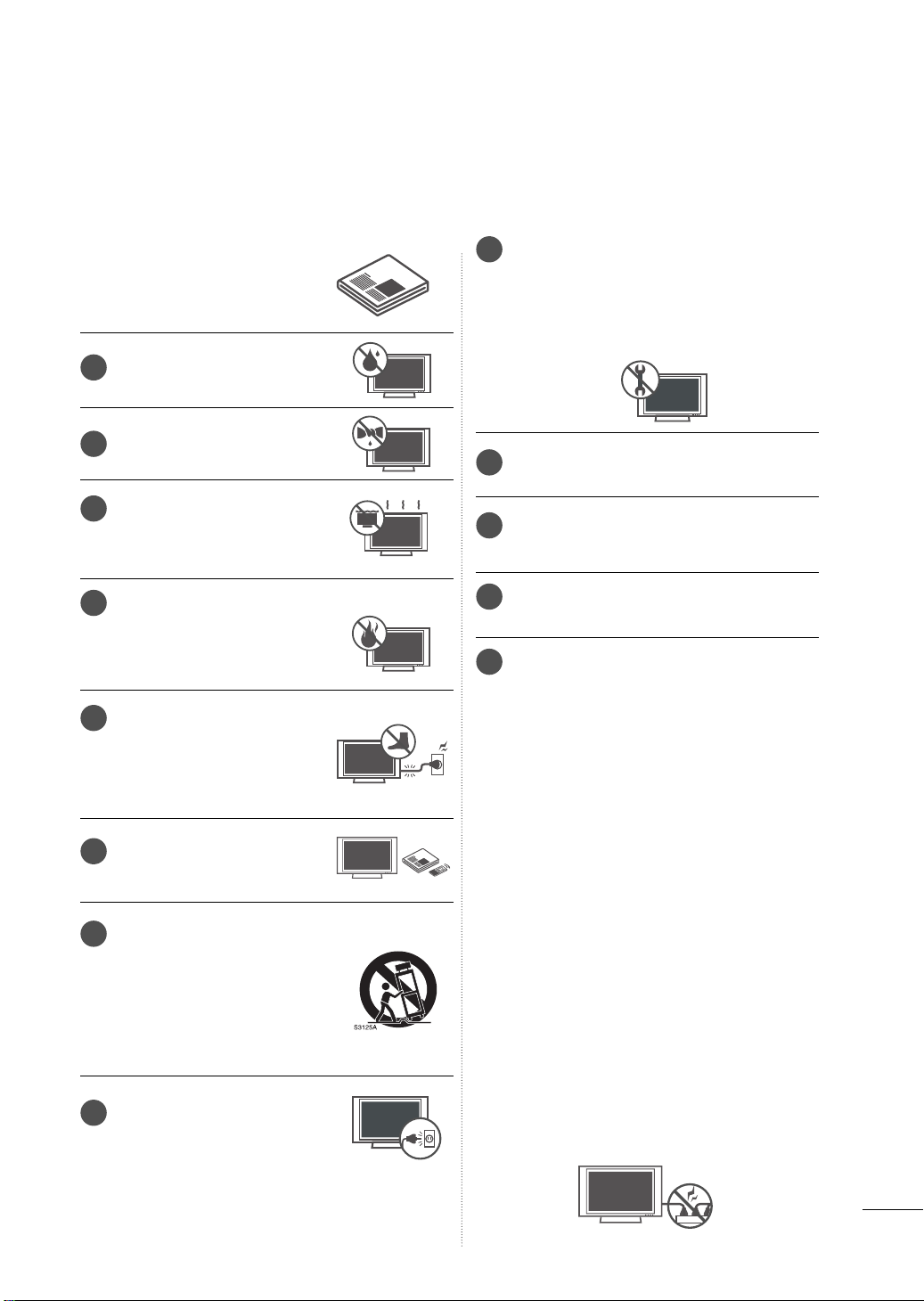
Do not use this apparatus
1
near water.
Clean only with dry cloth.
2
Do not block any ventilation
3
openings. Install in accordance
with the manufacturer’s
instructions.
Do not install near any heat
4
sources such as radiators,
heat registers, stoves, or other
apparatus (including amplifiers) that produce heat.
Protect the power cord from
5
being walked on or pinched
particularly at plugs, convenience receptacles, and the
point where they exit from the
apparatus.
Only use attachments/acces-
6
sories specified by the manufacturer.
Use only with the cart, stand,
7
tripod, bracket, or table specified by the manufacturer, or
sold with the apparatus. When
a cart is used, use caution
when moving the cart/apparatus combination to avoid injury
from tip-over.
Unplug this apparatus during
8
lighting storms or when unused
for long periods of time.
Refer all servicing to qualified service personnel. Servicing is required when the appa-
9
ratus has been damaged in any way, such
as power-supply cord or plug is damaged,
liquid has been spilled or objects have fallen
into the apparatus, the apparatus has been
exposed to rain or moisture, does not operate normally, or has been dropped.
Never touch this apparatus or antenna dur-
10
ing a thunder or lighting storm.
When mounting a TV on the wall, make sure
11
not to install the TV by the hanging power
and signal cables on the back of the TV.
Do not allow an impact shock or any objects
12
to fall into the product, and do not drop
onto the screen with something.
CAUTION concerning the Power Cord:
13
It is recommend that appliances be placed
upon a dedicated circuit; that is, a single
outlet circuit which powers only that appliance and has no additional outlets or
branch circuits. Check the specification
page of this owner's manual to be certain.
Do not connect too many appliances to the
same AC power outlet as this could result in
fire or electric shock.
Do not overload wall outlets. Overloaded
wall outlets, loose or damaged wall outlets,
extension cords, frayed power cords, or
damaged or cracked wire insulation are
dangerous . Any of these conditions could
result in electric shock or fire. Periodically
examine the cord of your appliance, and if its
appearance indicates damage or deterioration, unplug it, discontinue use of the appliance, and have the cord replaced with an
exact replacement part by an authorized
servicer. Protect the power cord from physical or mechanical abuse, such as being
twisted, kinked, pinched, closed in a door, or
walked upon. Pay particular attention to
plugs, wall outlets, and the point where the
cord exits the appliance.
Do not make the TV with the power cord
plugged in. Do not use a damaged or loose
power cord. Be sure do grasp the plug
when unplugging the power cord. Do not
pull on the power cord to unplug the TV.
3
SAFETY INSTRUCTIONS
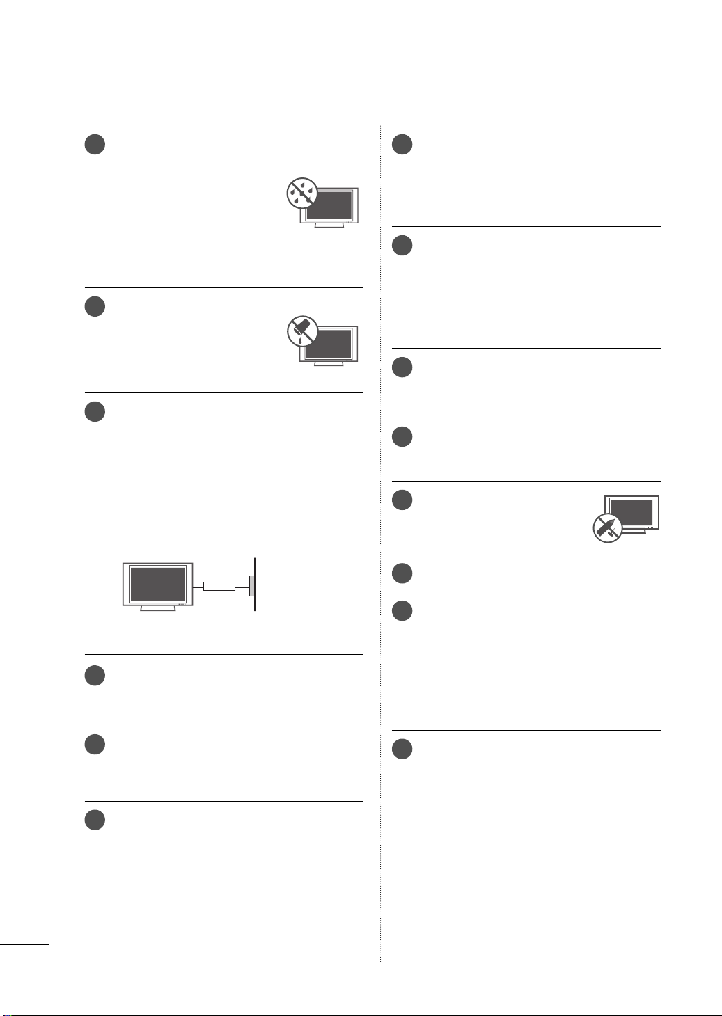
WARNING - To reduce the risk
14
of fire or electrical shock, do not
expose this product to rain,
moisture or other liquids. Do
not touch the TV with wet
hands. Do not install this product near flammable objects
such as gasoline or candles or
expose the TV to direct air
conditioning.
Do not expose to dripping or
15
splashing and do not place
objects filled with liquids, such
as vases, cups, etc. on or over
the apparatus (e.g. on shelves
above the unit).
GROUNDING
16
Ensure that you connect the earth ground wire
to prevent possible electric shock (i.e. a TV with
a three-prong grounded AC plug must be connected to a three-prong grounded AC outlet). If
grounding methods are not possible, have a
qualified electrician install a separate circuit
breaker.
Do not try to ground the unit by connecting it to
telephone wires, lightening rods, or gas pipes.
Moving
20
Make sure the product is turned off,
unplugged and all cables have been
removed. It may take 2 or more people to
carry larger TVs. Do not press against or put
stress on the front panel of the TV.
Ventilation
21
Install your TV where there is proper ventilation. Do not install in a confined space such
as a bookcase. Do not cover the product
with cloth or other materials (e.g.) plastic
while plugged in. Do not install in excessively dusty places.
Take care not to touch the ventilation open-
22
ings. When watching the TV for a long
period, the ventilation openings may
become hot.
If you smell smoke or other odors coming
23
from the TV, unplug the power cord and contact and authorized service center.
Do not press strongly upon the
24
panel with hand or sharp object
such as nail, pencil or pen, or
make a scratch on it.
Power
Supply
Short-circuit
Breaker
DISCONNECTING DEVICE FROM MAINS
17
Mains plug is the disconnecting device. The
plug must remain readily operable.
As long as this unit is connected to the AC
18
wall outlet, it is not disconnected from the AC
power source even if you turn off this unit by
SWITCH.
Cleaning
19
When cleaning, unplug the power cord and
scrub gently with a soft cloth to prevent
scratching. Do not spray water or other liquids
directly on the TV as electric shock may
occur. Do not clean with chemicals such as
alcohol, thinners or benzene.
Keep the product away from direct sunlight.
25
Dot Defect
26
The Plasma or LCD panel is a high technology product with resolution of two million to
six million pixels. In a very few cases, you
could see fine dots on the screen while
you’reviewing the TV. Those dots are deactivated pixels and do not affect the performance and reliability of the TV.
Generated Sound
27
“Cracking” noise: A cracking noise that occurs
when watching or turning off the TV is generated by plastic thermal contraction due to
temperature and humidity. This noise is common for products where thermal deformation
is required.
Electrical circuit humming/panel buzzing: A
low level noise is generated from a high-speed
switching circuit, which supplies a large amount
of current to operate a product. It varies
depending on the product.
This generated sound does not affect the performance and reliability of the product.
4
For LED LCD TV/LCD TV
28
If the TV feels cold to the touch, there may be
a small “flicker” when it is turned on. This is
normal, there is nothing wrong with TV.
Some minute dot defects may be visible on
the screen, appearing as tiny red, green, or
blue spots. However, they have no adverse
effect on the monitor’s performance.
Avoid touching the LCD screen or holding your
finger(s) against it for long periods of time.
Doing so may produce some temporary distortion effects on the screen.
Viewing 3D Imaging (For 3D TV)
29
►When viewing 3D imaging, watch the TV
from an eff
in the appropriate distance. If you exceed
this viewing angle or distance, you may not
be able to view the 3D imaging. Furthermore, the 3D imaging may not display if it
is viewed while you are lying down.
►If you watch the 3D imaging too closely or
f
or a long period of time, it may harm
eyesight.
►Watching the TV or playing video games
that incorporate 3D imaging
glasses for a long period of time can cause
drowsiness, headaches or fatigue to you
and/or your eyes. If you have a headache,
or otherwise feel fatigued or drowsy, stop
watching the TV and take a rest.
►Pregnant woman, seniors, persons with
hear
frequent drowsiness should refrain from
watching 3D TV.
►Some 3D imaging may cause you to duck
or dodge the image displayed in the video.
Therefore, it is best if you do not watch 3D
TV near fragile objects or near any objects
that can be knocked over easily.
► Please prevent children under the age of 5
from watching 3D TV. It may affect their vision development.
►Warning for photosensitization seizure:
Some viewers may experience a seizure
or epilepsy when exposed t
tors, including fl ashing lights or images in
TV or video games. If you or anybody from
your family has a history of epilepsy or seizure, please consult with your doctor before
watching 3D TV.
ective viewing angle and with-
with the 3D
oblems or persons who experience
t pr
o certain fac-
your
Also certain symptoms can occur in unspecifi ed conditions without any previous history. If you experience any of the
following symptoms, immediately stop
watching the 3D imaging and consult a
doctor: dizziness or lightheadedness, visual transition or altered vision, visual or
facial instability, such as eye or muscle
twitching, unconscious action, convulsion,
loss of conscience, confusion or disorientation, loss of directional sense, cramps,
or nausea. Parents should monitor their
children, including teenagers, for these
symptoms as they may be more sensitive
to the effects of watching 3D TV.
Risk of photosensitization seizure can be
reduced with the following actions.
- Take frequent breaks from watching 3D
TV.
- For those who have vision that is differ-
ent in each eye, they should watch the
TV after taking vision correction measures.
- Watch the TV so that your eyes are on
the same level as the 3D screen and
refrain from sitting too closely to the TV
- Do not watch the 3D imaging when
tired or sick, and avoid watching the 3D
imaging for a long period of time.
- Do not wear the 3D glasses for any oth-
er purpose than viewing 3D imaging on
a 3D TV.
- Some viewers may feel disoriented after
watching 3D TV. Therefore, after you watch
3D TV, take a moment to regain awareness of your situation before moving.
ON DISPOSAL
(Only Hg lamp used LCD TV)
The fluorescent lamp used in this product
contains a small amount of mercury. Do
not dispose of this product with general
household waste. Disposal of this product
must be carried out in accordance to the
regulations of your local authority.
5

CONTENTS
WARNING / CAUTION
SAFETY INSTRUCTIONS
FEATURE OF THIS TV
PREPARATION
Accessories .............................................................9
Optional Extras ....................................................10
Front Panel Information ..................................... 11
Back Panel Information .....................................13
Stand Instructions ................................................
VESA Wall Mounting ........................................20
Cable Management ...........................................21
Desktop Pedestal Installation .........................23
Swivel Stand ........................................................23
Attaching the TV to a desk .............................24
Kensington Security System .......................... 24
Securing the TV to the wall to prevent falling
when the TV is used on a stand ...................25
Antenna or Cable Connection .......................26
................................2
..........................3
................................ 8
16
Channel Selection..............................................56
Volume Adjustment ..........................................56
Initial Setting ....................................................... 57
On-Screen Menus Selection ..........................58
Quick Menu .......................................................... 61
Customer Support
-Software Update .......................................62
-Picture Test/Sound Test ..........................63
-Diagnostics .................................................63
-Product/Service Info. ...............................64
-Network Test. ..............................................64
Simple Manual ....................................................65
Channel Setup
-Auto Scan (Auto Tuning) ........................66
-Add/Delete Channel (Manual Tuning) 67
-Channel Editing .........................................68
Favorite Channel Setup .................................... 69
Favorite Channel List ........................................ 69
Channel List ........................................................ 70
Input List ............................................................... 71
Input Label ............................................................ 71
Mode Setting ...................................................... 72
Demo Mode ........................................................ 72
Reset to Factory Default(Initial Setting)....... 73
System Color ....................................................... 73
AV Mode ............................................................... 74
Game ..................................................................... 74
Simplink ................................................................ 75
EPG ........................................................................ 76
EXTERNAL EQUIPMENT SETUP
HD Receiver Setup ............................................ 27
DVD SETUP .........................................................30
VCR SETUP .........................................................33
Other A/V Source Setup .................................35
USB Connection ................................................36
Headphone Setup
Audio Out Connection ..................................... 37
External Equipment Wireless Connection
(Optional Extra) ...................................................38
PC Setup ..............................................................39
Network Setup ....................................................44
.....................................................36
BLUETOOTH
Bluetooth? ........................................................... 80
Setting the Bluetooth ........................................81
Connecting the Bluetooth Headset ............82
Remove the Bluetooth Device .......................84
My Bluetooth Information ................................85
Viewing the Photos with Bluetooth Device ......86
Listening the Musics with Bluetooth Device ...86
3D IMAGING
3D Technology .................................................... 87
WATCHING TV / CHANNEL CONTROL
Remote Control Functions ..............................52
Turning on the TV .............................................. 56
Watching 3D Imaging ......................................88
6

MY MEDIA
SOUND & LANGUAGE CONTROL
Entry Mode ..........................................................90
Connection Method ........................................... 91
Movie List ............................................................. 96
Photo List ........................................................... 103
Music List ........................................................... 109
DivX Registration Code ................................... 114
Deactivation ........................................................ 115
NETWORK
Legal Notice ....................................................... 116
NETCAST
Netcast Menu ..................................................... 118
Weather Information ........................................ 119
Photo Album ..................................................... 120
Video Online ....................................................... 121
EMOL .................................................................. 123
BAZUCA ............................................................. 124
TERRATV ............................................................ 125
PICTURE CONTROL
Picture Size (Aspect Ratio) Control ............ 126
Picture Wizard ................................................... 128
ꕊ Energy Saving ............................................130
Preset Picture Settings (Picture Mode) ...... 131
Manual Picture Adjustment - User Mode 132
Picture Improvement Technology (Advanced
Control) .............................................................. 133
Expert Picture Control .................................... 134
Picture Reset ......................................................137
TruMotion ...........................................................138
LED Local Dimming ........................................ 139
Power Indicator ................................................ 139
Image Sticking Minimization (ISM) Method. .....140
Auto Volume ....................................................... 141
Clear Voice II ..................................................... 142
Balance ............................................................... 143
Preset Sound Settings (Sound Mode) ...... 144
Sound Setting Adjustment - User Mode . 145
Audio Reset ....................................................... 146
TV Speakers On/Off Setup .......................... 146
Digital Audio Out ..............................................147
Stereo/SAP Broadcast Setup ...................... 148
DTV Audio Setting ..........................................148
ON-Screen Menus Language Selection ... 149
Caption Mode ................................................... 149
Language Selection ........................................150
TIME SETTING
Clock Setting ...................................................... 151
On/Off Time Setting ....................................... 152
Sleep Timer Setting ........................................ 153
PARENTAL CONTROL
Set Password & Lock System
-Setting up Your Password ................... 154
-Set Password .......................................... 155
-Lock System............................................156
Channel Blocking ..............................................157
External Input Blocking .................................. 158
Key Lock ............................................................. 159
APPENDIX
Troubleshooting ................................................160
Maintenance ...................................................... 163
Product Specifications ................................... 164
IR Codes ..............................................................167
External Control Through RS-232C .......... 168
Open Source Software Notice ......................175
7
FEATURE OF THIS TV
ꔛ
Some of these features are not available on all models.
Manufactured under license from
Dolby Laboratories. “Dolby “and the
double-D symbol are trademarks of
Dolby Laboratories.
Listen to TV with wireless headset,
or enjoy viewing your mobile phone
photos on your TV.
(This is not available for all models.)
HDMI, the HDMI logo and HighDefinition Multimedia Interface are
trademarks or registered trademarks of HDMI Licensing LLC."
ABOUT DIVX VIDEO: DivX® is a digital video
format created by DivX, Inc. This is an official
DivX Certified device that plays DivX video.
Visit www.divx.com for more information and
software tools to
convert your files into DivX video.
ABOUT DIVX VIDEO-ON-DEMAND: This DivX
Certified® device must be registered in order
to play DivX Video-on-Demand (VOD) content. To generate the registration code, locate
the DivX VOD section in the device setup
menu. Go to vod.divx.com with this code to
complete the registration process and learn
more about DivX VOD.
“DivX Certified® to play DivX® video up to HD
1080p, including premium content.”
“DivX®, DivX Certified® and associated logos
are trademarks of DivX, Inc. and are used
under license.”
“Pat. 7,295,673; 7,460,668; 7,515,710;
7,51 9, 274 ”
IMPORTANT INFORMATION TO PREVENT “IMAGE
BURN / BURN-IN” ON YOUR TV SCREEN
ꔛ
When a fixed image (e.g. logos, screen menus, video game, and computer display) is displayed
on the TV for an extended period, it can become permanently imprinted on the screen. This
phenomenon is known as “image burn” or “burn-in.” Image burn is not covered under the manufacturer’s warranty.
ꔛ
In order to prevent image burn, avoid displaying a fixed image on your TV screen for a prolonged
period (2 or more hours for LCD, 1 or more
hours for Plasma).
ꔛ
Image burn can also occur on the letterboxed areas of your TV if you use the 4:3
aspect ratio setting for an extended period.
8
PREPARATION
1.5V 1.5V
ENERGY
CHVOL
12
ABC
3
DEF
4
GHI
5
JKL
6
MNO
7
PQRS
8
TUV
0
9
WXYZ
P
A
G
E
SAVING
TV
AV MODE
INPUT
LIGHT
FAV
RATIO
MUTE
BACK
EXIT
ENTER
MARK
DELETE
CHAR/NUM
LIST
FLASHBK
MENU
FREEZE
Q.MENU
INFO
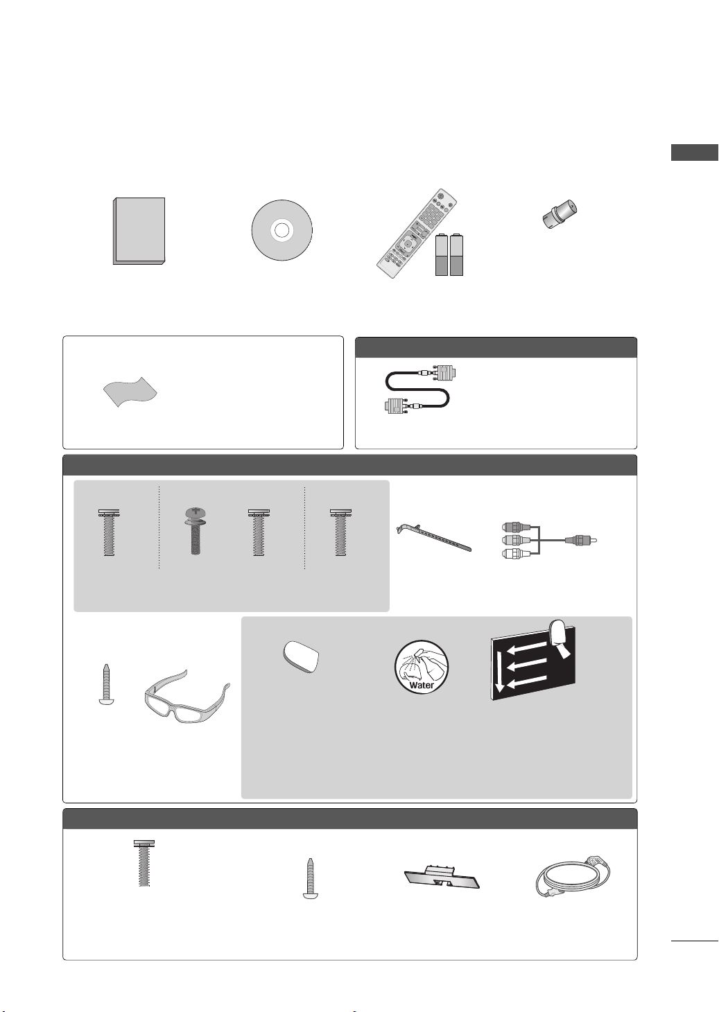
ACCESSORIES
Ensure that the following accessories are included with your TV. If an accessory is missing, please contact the dealer where you purchased the TV.
The accessories included may differ from the images below.
RF Adapter
(Some models)
You must connect it to the antenna
Owner’s Manual Nero MediaHome 4
Essentials CD
Remote Control,
Batteries (AAA)
(Some models)
wire after fixing in Antenna Input.
This adapter is only supplied in
Argentina.
PREPARATION
Not included with all models
* Wipe spots on the exterior only
with the polishing cloth.
* Do not wipe roughly when remov-
Polishing Cloth
ing stain. Excessive pressure may
cause scratch or discoloration.
Option Extras
D-sub 15 pin Cable
When using the VGA (D-sub 15
pin cable) PC connection, the
user must use shielded signal
interface cables with ferrite cores
to maintain standards compliance.
32/42/47/55LE5500, 42LE5550, 32/42/47/55LE7500, 42/47LE8500, 42/47LX6500
(Other models)
(For 55LE5500, 55LE7500)
x 8
(M4 x 16)
Screws for stand assembly
(Refer to P.18)
(For 32LE5500,
32LE7500)
(For 42/47LX6500)
x 4x 4
(M4 x 16)(M4 x 24)
(For 32/42/47/55LE7500)
(42/47LE8500)
x 8
(M4 x 20)
Cable Holder
(Refer to p.22)
Component gender cable,
AV gender cable
Cleansing Cloths
(mitt)
Screw for
stand fixing
(Refer to
P. 2 4 )
3D Glasses
* Wipe spots on the exterior only with the cleansing cloths.
* Do not wipe roughly when removing stains. Excessive pressure may cause scratches or
discoloration.
* For cleaning front frame, please slowly wipe in one direction after spraying water 1-2 times
on cleansing cloths. Please remove excessive moisture after cleaning. Excessive moisture
may cause water stains on the frame.
x 2
32/42/47/55LD650
(For 32/42LD650)
x 8
(M4 x 20)
Screws for stand assembly
(Refer to P.16)
Screw for stand fixing
(Refer to P.24)
Protection Cover
(Refer to P.16)
Power Cord
9
PREPARATION
CH
Q.VIEW
VOL
POWER TV/INPUT
1.5V 1.5V
Plasma TV
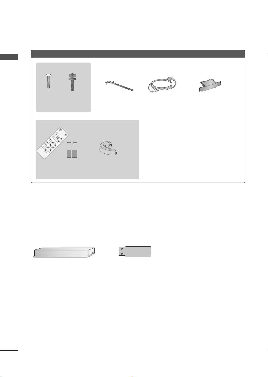
PREPARATION
(For 50PK950R)
x 4
x 4
x 2
(M4 x 14) (M4 x 28)
Screws for stand assembly
(Refer to P.17)
(For50/60PK950R)
Remote Control,
Batteries (AAA)
(Some models)
Cable Holder
(Refer to P.22)
Cable
Management Clip
Power Cord
Protection Cover
(Refer to P.17)
OPTIONAL EXTRAS
Optional extras can be changed or modified for quality improvement without any notification.
Contact your dealer for buying these items.
This device only works with compatible LG LED LCD TV, LCD TV or PLASMA TV.
10
Wireless Media Box
(AN-WL100W)
Wireless LAN for Broadband/
DLNA Adaptor
(AN-WF100)
CH
VOL
ENTER
INPUT
MENU
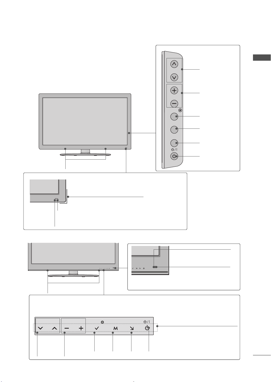
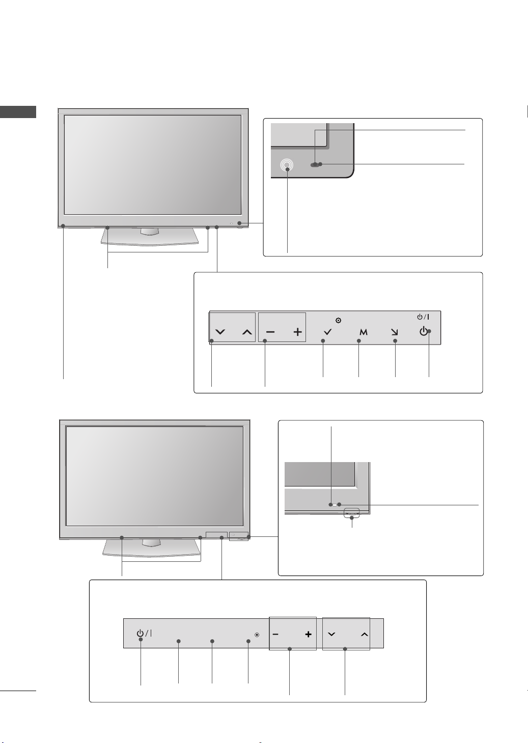
FRONT PANEL INFORMATION
VOL ENTERCH MENU INPUT
ꔛ
Image shown may differ from your TV.
32/42/47/55LD650
SPEAKER
Power/Standby Indicator
(Can be adjusted using the Power Indicator in the
OPTION menu.
►p.139)
CHANNEL
(
ꕌ,ꕍ) Buttons
VOLUME (+, -)
Buttons
ENTER Button
MENU Button
INPUT Button
POWER Button
PREPARATION
42/47LE8500
Touch Button
You can operate the button just by touching the button lightly with your finger.
Intelligent Sensor
Adjusts picture according to the surrounding conditions
SPEAKER
CHANNEL
(
ꕍ,ꕌ)
Buttons
Remote Control Sensor
VOLUME
(-, +)
ENTER
Button
Buttons
MENU
Button
INPUT
Button
POWER
Button
Remote Control Sensor
Intelligent Sensor
Adjusts picture according to
the surrounding conditions
Power/Standby Indicator
(Can be adjusted using the
Power Indicator in the
OPTION menu.
►p.139)
11
PREPARATION
VOL ENTERCH MENU INPUT
32/42/47/55LE5500, 42LE5550, 32/42/47/55LE7500, 42/47LX6500
PREPARATION
SPEAKER
Emitter
(For 42/47LX6500)
It is the part equipped with
the emitter exchanging signal with 3D glasses.
Please be careful not to
block the screen with objects
or people while watching a
3D Video.
Remote Control Sensor
Intelligent Sensor
Adjusts picture according to
the surrounding conditions
Power/Standby Indicator
(Can be adjusted using the Power
Indicator in the OPTION menu.
Touch Button
Light the button by touching first. At this time, you can use the desired button.
CHANNEL
(
ꕍ,ꕌ)
Buttons
VOLUME
(-, +)
Buttons
ENTER
Button
MENU
Button
INPUT
Button
►p.139)
POWER
Button
50/60PK950R
Touch Button
You can operate the button just by touching the button lightly with your finger.
SPEAKER
POWER
Button
INPUT
INPUT
Button
MENU
ENTER
MENU
Button
ENTER
Button
Intelligent Sensor
Adjusts picture according to the
surrounding conditions
Remote Control Sensor
Power/Standby Indicator
Illuminates red in standby mode.
The lighting is off while the TV remains on.
VOL
VOLUME
(+, -)
Buttons
CH
CHANNEL
(
ꕌ,ꕍ)
Buttons
1212
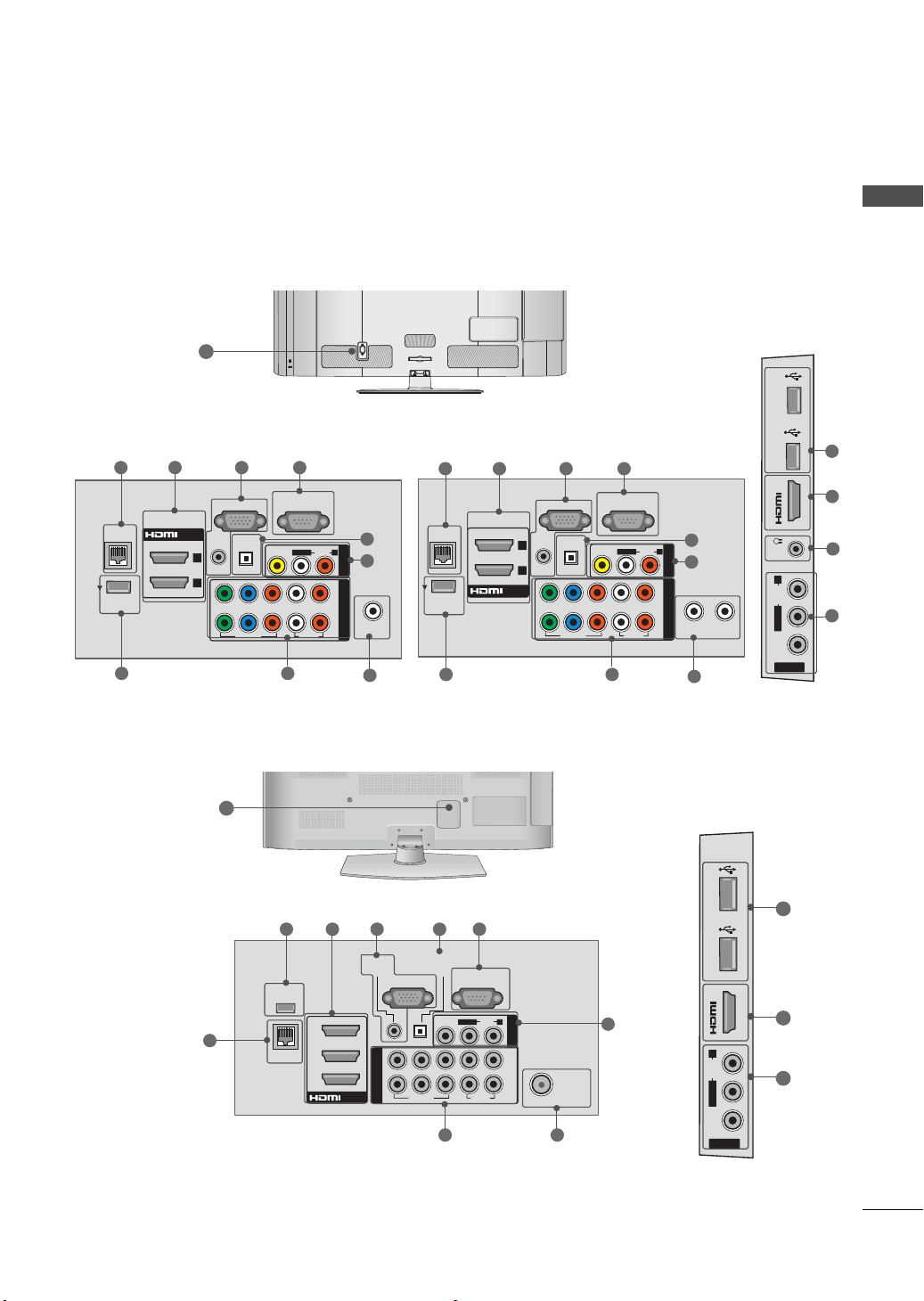
BACK PANEL INFORMATION
IN 3
H/P USB IN 1
AV IN 2
VIDEO
AUDIO
L/MONO
R
USB IN 2
ANTENNA/
CABLE IN
RGB IN (PC)
LAN
WIRELESS
CONTROL
RGB/DVI
OPTICAL DIGITAL
/DVI IN
2
1
VIDEO
AUDIO
L(MONO)
R
VIDEO
AUDIO
COMPONENT INAV IN 1
YPBP
R
LR
AUDIO IN
AUDIO OUT
2
1
RS-232C IN
(
CONTROL & SERVICE)
ANTENNA
IN
RGB IN (PC)
LAN
WIRELESS
CONTROL
RGB/DVI
OPTICAL DIGITAL
/DVI IN
2
1
CABLE IN
VIDEO
AUDIO
L(MONO)
R
VIDEO
AUDIO
COMPONENT INAV IN 1
YPBP
R
LR
AUDIO IN
AUDIO OUT
2
1
RS-232C IN
(
CONTROL & SERVICE)
CABLE MANAGEMENT
AC IN
ꔛ
Image shown may differ from your TV.
12
32/42/47/55LD650-MA 32/42/47/55LD650-DA
1 2 3 4
1 2 3 4
PREPARATION
11
1
9
50/60PK950R
12
1
8
9
WIRELESS
CONTROL
LAN
5
6
7
2 3 45
AUDIO IN
(RGB/DVI)
3
2
1
/DVI IN
AUDIO OUT
RGB IN (PC)
Y
P
B
COMPONENT IN
VIDEO
O
PTICAL
DIGITAL
VIDEO
9
RS-232C IN
(
CONTROL&SERVICE)
L/MONO
P
R
AUDIO
R
LR
AUDIO
2
1
AV IN 1
ANTENNA
/CABLE
78
5
6
10
3
8
7
10
USB IN 1 USB IN 2
IN 4
6
R
IN
AUDIO
L/MONO
VIDEO
AV IN 2
2
6
13
PREPARATION
ANTENNA/
CABLE IN
RGB IN (PC)
LAN
WIRELESS
CONTROL
(RGB/DVI)
OPTICAL DIGITAL
/DVI IN
2
3
1
VIDEO
AUDIO
L(MONO)
R
VIDEO
AUDIO
COMPONENT INAV IN 1
YPB PR
L R
AUDIO IN
AUDIO OUT
2
1
RS-232C IN
(
CONTROL & SERVICE)
COMPONENT IN3
AUDIO / Y P
B PR
IN 4
H/P
USB IN 1 USB IN 2
AV IN2
VIDEO / AUDIO
ANTENNA
IN
RGB IN (PC)
LAN
WIRELESS
CONTROL
(RGB/DVI)
OPTICAL DIGITAL
/DVI IN
2
3
1
VIDEO
AUDIO
L(MONO)
R
VIDEO
AUDIO
COMPONENT INAV IN 1
YPB PR
L R
AUDIO IN
AUDIO OUT
2
1
CABLE IN
RS-232C IN
(
CONTROL & SERVICE)
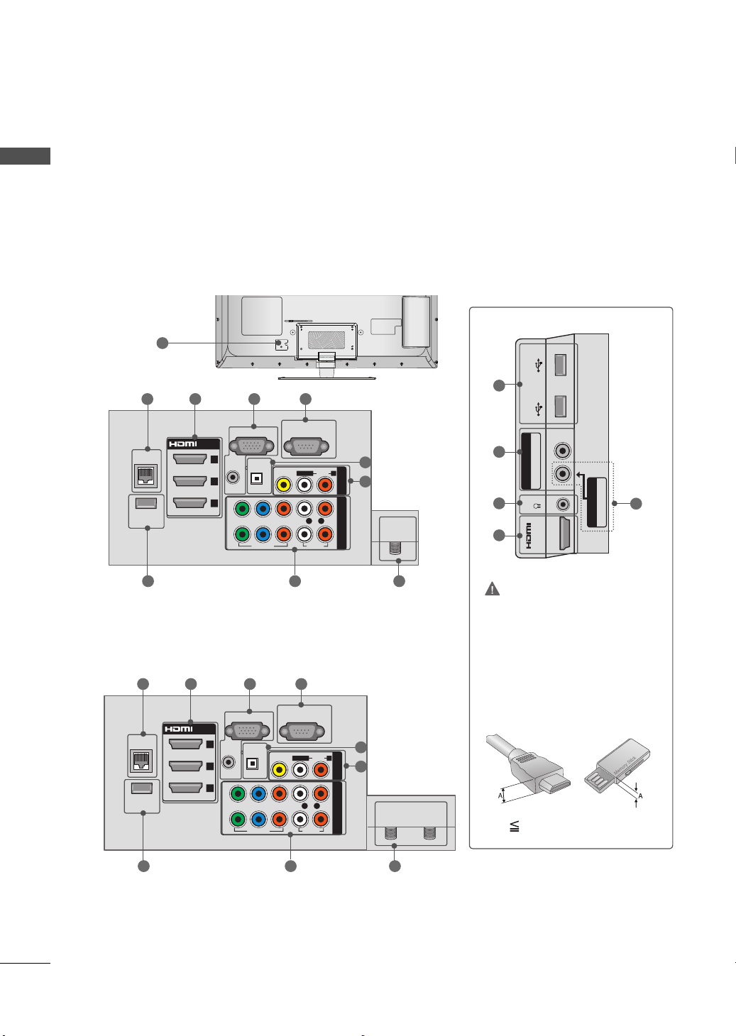
PREPARATION
32/42/47/55LE5500-MA, 32/42/47/55LE7500-MA, 42/47LE8500-MA
12
1 2 3 4
5
6
8 79
32/42/47/55LE5500-DA, 42LE5550-DA, 42/47LX6500,
42/47LE8500-DA
1 2 3 4
5
6
10
8
11
6
2
CAUTION
For HDMI IN 4 and USB IN
1/2
► For an optimal connection,
HDMI cables and USB
devices should have bezels
less than 0.39 inches (10
mm) thick.
14
8 79
*A 0.39 inches (10 mm)

PREPARATION
1
LAN
Network connection for Netcast services.
Also used for photo and music files on local
network.
2
HDMI/DVI IN, HDMI IN
Digital Connection.
Supports HD video and Digital audio. Doesn’t
support 480i.
Accepts DVI video using an adapter or HDMI
to DVI cable (not included).
3
RGB IN (PC)
Analog PC Connection. Uses a D-sub 15 pin
cable (VGA cable).
AUDIO IN (RGB/DVI)
1/8” (0.32 cm) headphone jack for analog PC
audio input.
4
RS-232C IN (CONTROL & SERVICE) PORT
Used by third party devices.
This port is used for service or Hotel mode.
5
OPTICAL DIGITAL AUDIO OUT
Digital optical audio output for use with amps
and home theater systems.
Note: In standby mode, this port doesn’t work.
7
ANTENNA/CABLE IN
Connect over-the air signals to this jack.
Connect cable signals to this jack.
8
COMPONENT IN
Analog Connection.
Supports HD.
Uses a red, green, and blue cable for video &
red and white for audio.
9
WIRELESS CONTROL
Connect the Wireless Dongle to the TV to
control the external input devices connected
to Media Box wirelessly.
10
USB INPUT
Used for viewing photos, movies and listen-
ing to MP3s.
11
HEADPHONE INPUT
0.32 cm (1/8 inch) headphone jack
Impedance 16 Ω , Maximum audio out 15 mW
12
Power Cord Socket
For operation with AC power.
Caution: Never attempt to operate the TV on
DC power.
6
AV (Audio/Video) IN
Analog composite connection. Supports stan-
dard definition video only (480i).
15
PREPARATION
!
AC IN
CABLE MANAGEMENT
AC IN
CABLE MANAGEMENT
AC IN
CABLE MANAGEMENT
AC IN
CABLE MANAGEMENT
AC IN
CABLE MANAGEMENT
AC IN
CABLE MANAGEMENT
PREPARATION
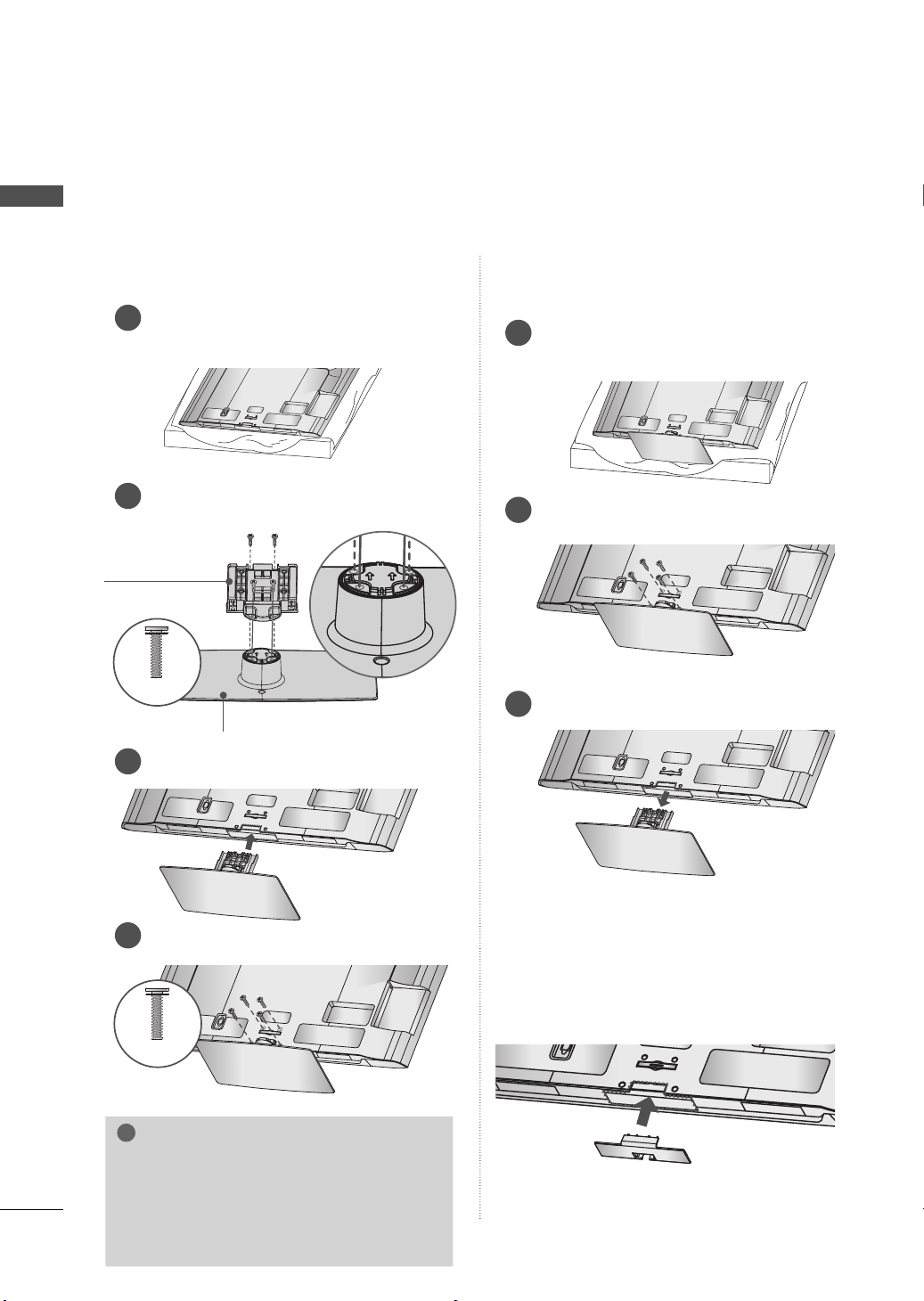
STAND INSTRUCTIONS
ꔛ
Image shown may differ from your TV.
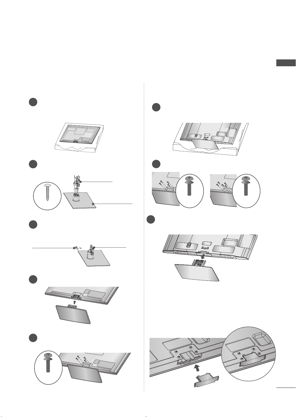
(For 32/42/47/55LD650)
INSTALLATION
Carefully place the TV screen side down on
1
a cushioned surface to protect the screen
from damage.
Assemble the parts of the STAND BODY
2
with the STAND BASE of the TV.
STAND BODY
M4 x 20
STAND BASE
DETACHMENT
Carefully place the TV screen side down on
1
a cushioned surface to protect the screen
from damage.
Remove the screws that hold the stand on.
2
Detach the stand from TV.
3
16
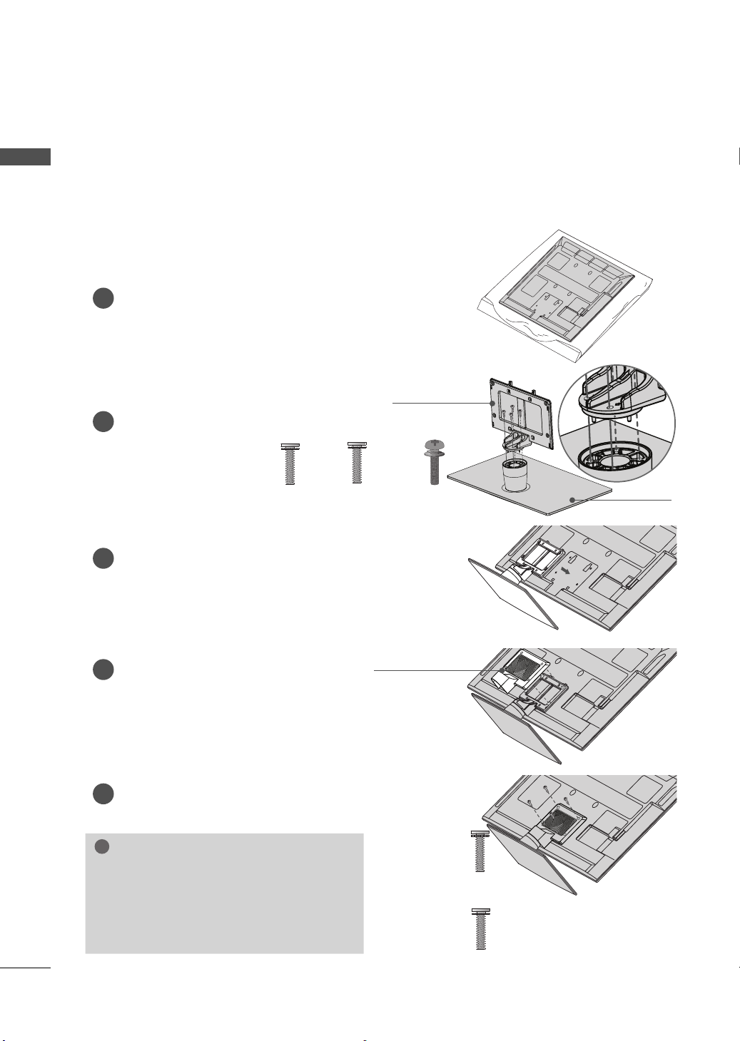
Assemble the TV as shown.
3
PROTECTION COVER
Fix the 4 screws securely using the holes in
4
the back of the TV.
M4 x 20
NOTE
► When assembling the desk type stand,
make sure the screws are fully tightened (If
not tightened fully, the TV can tilt forward
after the product installation). Do not over
tighten.
After removing the stand, install the included
PROTECTION COVER over the hole for the
stand.
Press the PROTECTION COVER into the TV until
you hear it click.
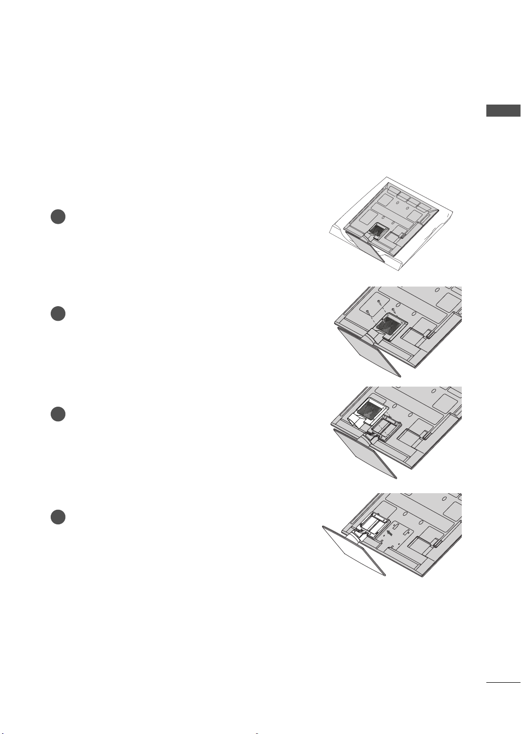
(For 50/60PK950R)
AC IN
CABLE MANAGEMENT
AC IN
CABLE MANAGEMENT
ꔛ
Image shown may differ from your TV.
PREPARATION
INSTALLATION
Carefully place the TV screen side down on
1
a cushioned surface to protect the screen
from damage.
Assemble the parts of the STAND BODY
2
with the STAND BASE of the TV.
M4 x 14
Assemble the parts of the CABLE
3
MANAGEMENT CLIP with the STAND
BODY.
(For 50PK950R)
STAND BODY
STAND BASE
DETACHMENT
Carefully place the TV screen side down on
1
a cushioned surface to protect the screen
from damage.
Remove the screws that hold the stand on.
2
50PK950R
Detach the stand from TV.
3
60PK950R
M4 x 30M4 x 28
CABLE
MANAGEMENT
CLIP
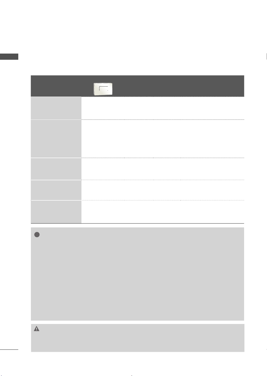
Assemble the TV as shown.
4
Fix the 4 screws securely using the holes
5
in the back of the TV.
M4 x 28
STAND BODY
PROTECTION COVER
After removing the stand, install the included
PROTECTION COVER over the hole for the
stand.
Press the PROTECTION COVER into the TV until
you hear it click.
17
PREPARATION
!
PREPARATION
(For 32/42/47/55LE5500, 42LE5550, 32/42/47/55LE7500, 42/47LE8500, 42/47LX6500)
ꔛ
Image shown may differ from your TV.
INSTALLATION
1
Carefully place the TV screen side down on
a cushioned surface to protect the screen
from damage.
Assemble the parts of the STAND BODY
2
with the STAND BASE of the TV.
M4 x 20
(42/47LE8500)
Assemble the TV as shown.
3
M4 x 16
(Other models)
STAND BODY
M4 x 24
(55LE5500,
55LE7500)
STAND BASE
Assemble the part of the STAND
4
REAR COVER with the TV.
Fix the 4 screws securely using the holes in
5
the back of the TV.
STAND REAR
COVER
NOTE
► When assembling the desk type stand,
make sure the screws are fully tightened (If
not tightened fully, the TV can tilt forward
after the product installation). Do not over
tighten.
M4 x 16
(Other models)
M4 x 20
(42/47LE8500)
18
DETACHMENT
Carefully place the TV screen side down on
1
a cushioned surface to protect the screen
from damage.
Remove the screws that hold the stand on.
2
PREPARATION
Detach the STAND REAR COVER from TV.
3
Detach the stand from TV.
4
19
PREPARATION
!
VESA WALL MOUNTING
Install your wall mount on a solid wall perpendicular to the floor. When attaching to other building materials, please contact your nearest installer.
PREPARATION
If installed on a ceiling or slanted wall, it may fall and result in severe personal injury.
We recommend that you use an LG brand wall mount when mounting the TV to a wall.
LG recommends that wall mounting be performed by a qualified professional installer.
Model
32LD650,
32LE5500,
32LE7
500
42/47LD650,
42/47LE5500,
42LE5550,
42/47LX6500,
42/47LE7500,
42/47LE8500
55LD650,
55LE7500,
55LE5500
50PK950R 400
60PK950R 600
VESA (A * B)
A
B
200
100 M4 4
*
200
200 M6 4
*
400
400 M6 4
*
400 M6 4
*
400 M8 4
*
Standar
Screw
Quantity
Wall Mounting Bracket
(sold separately)
LSW100B, LSW100BG
LSW200B, LSW200BG
LSW400B, LSW400BG,
DSW400BG
PSW400B , PSW400BG
PSW600B, PSW600BG
NOTE
► Screw length needed depends on the wall
mount used. For further information, refer to
the instructions included with the mount.
► Standard dimensions for wall mount kits are
shown in the table.
►
When purchasing our wall mount kit, a detailed
installation manual and all par
assembly are provided.
► Do not use screws longer than the standard
dimension, as they may cause damage t
inside to the TV.
► For wall mounts that do not comply with the
VESA s
tandard screw specifications, the length
ts necessary for
o the
of the screws may differ depending on their
specifications.
► Do not use screws that do not comply with the
VESA s
Do not use fasten the screws too strongly, this
may damage the TV or cause the TV to a fall,
leading to personal injury. LG is not liable for
these kinds of accidents.
► LG is not liable for TV damage or personal
injur
mount is used or the consumer fails to follow
the TV installation instructions.
tandard screw specifications.
when a non-VESA or non specified wall
y
CAUTION
► Do not install your wall mount kit while your TV is turned on. It may result in personal injury due to
electric shock.
20
CABLE MANAGEMENT
AC IN
AC IN
AC IN
ꔛ
Image shown may differ from your TV.
32/42/47/55LD650
Connect the cables as necessary.
1
To connect additional equipment, see the
EXTERNAL EQUIPMENT SETUP section.
Open the CABLE MANAGEMENT CLIP as
2
shown.
PREPARATION
Put the cables inside the CABLE
3
MANAGEMENT CLIP and snap it closed.
CABLE MANAGEMENT CLIP
21
PREPARATION
32/42/47/55LE5500, 42LE5550, 32/42/47/55LE7500, 42/47LE8500, 42/47LX6500
PREPARATION
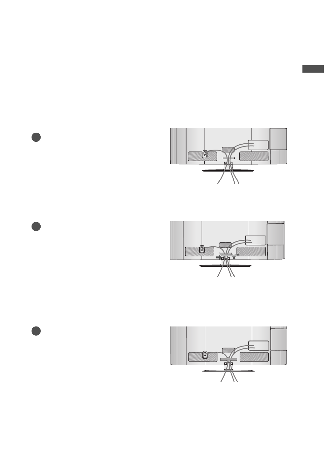
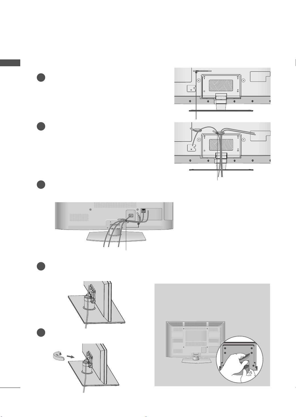
Secure the power cord with the CABLE
1
HOLDER on the TV back cover.
It will help prevent the power cable from
being removed by accident.
After connecting the cables as necessary,
2
install the CABLE HOLDER as shown
and bundle the cables.
Plasma TV
After connecting the cables as necessary,
1
install the CABLE HOLDER as shown
and bundle the cables.
CABLE HOLDER
CABLE HOLDER
22
(For 50/60PK950R)
Connect the cables as necessary.
1
To connect additional equipment, see the
EXTERNAL EQUIPMENT SETUP section.
Install the CABLE MANAGEMENT CLIP
2
into the TV until clicking sound.
CABLE HOLDER
HOW TO REMOVE THE CABLE
MANAGEMENT CLIP
► Hold the CABLE MANAGEMENT CLIP with
both hands and pull it backward as shown.
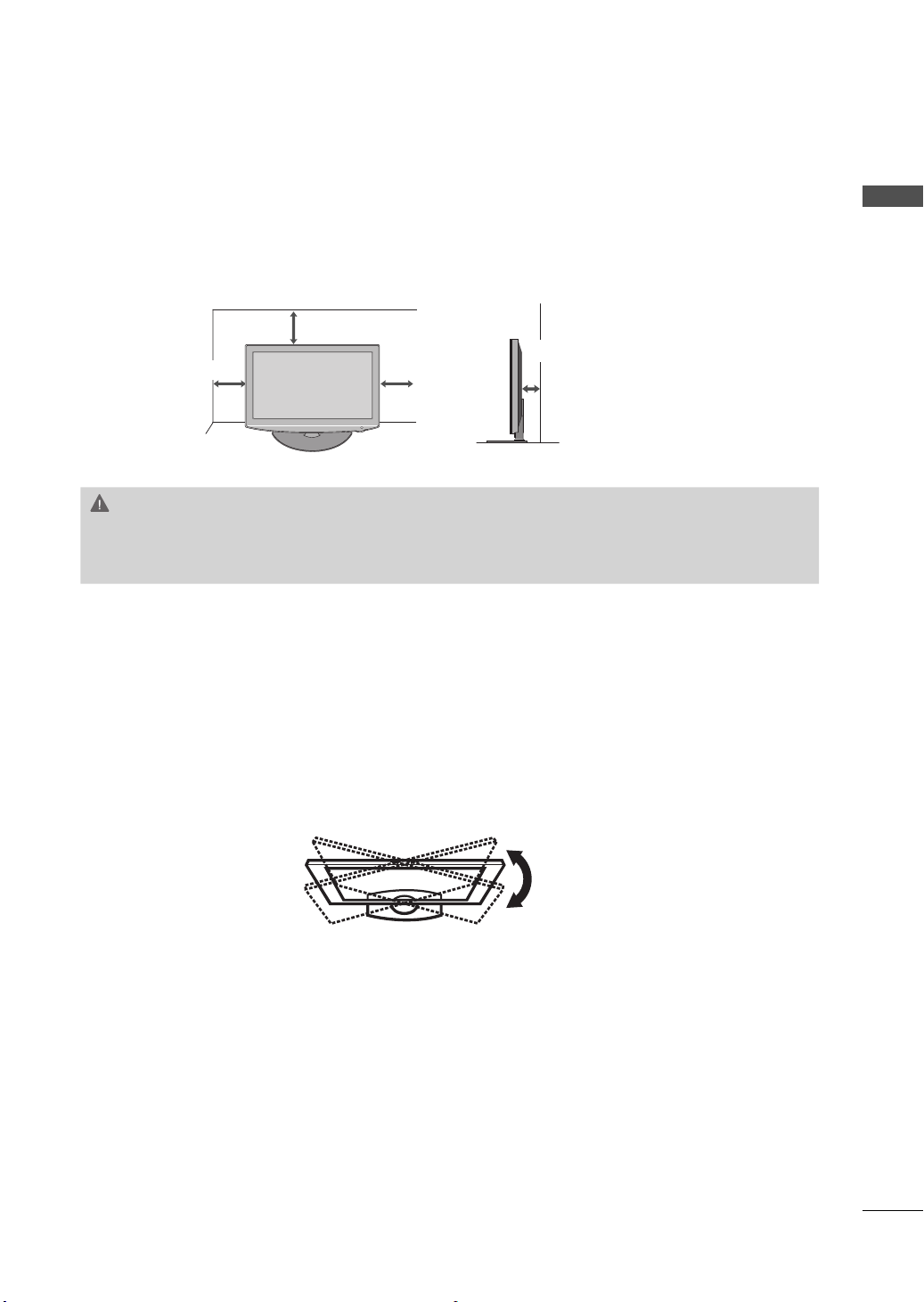
DESKTOP PEDESTAL INSTALLATION
ꔛ
Image shown may differ from your TV.
For proper ventilation, allow a clearance of 4 inches on all four sides from the wall.
4 inches
4 inches
4 inches
CAUTION
► Ensure adequate ventilation by following the clearance recommendations.
► Do not mount near or above any type of heat source.
4 inches
PREPARATION
SWIVEL STAND
After installing the TV, you can adjust the TV set manually to the left or right direction by 20 degrees
to suit your viewing position.
23
PREPARATION
PREPARATION
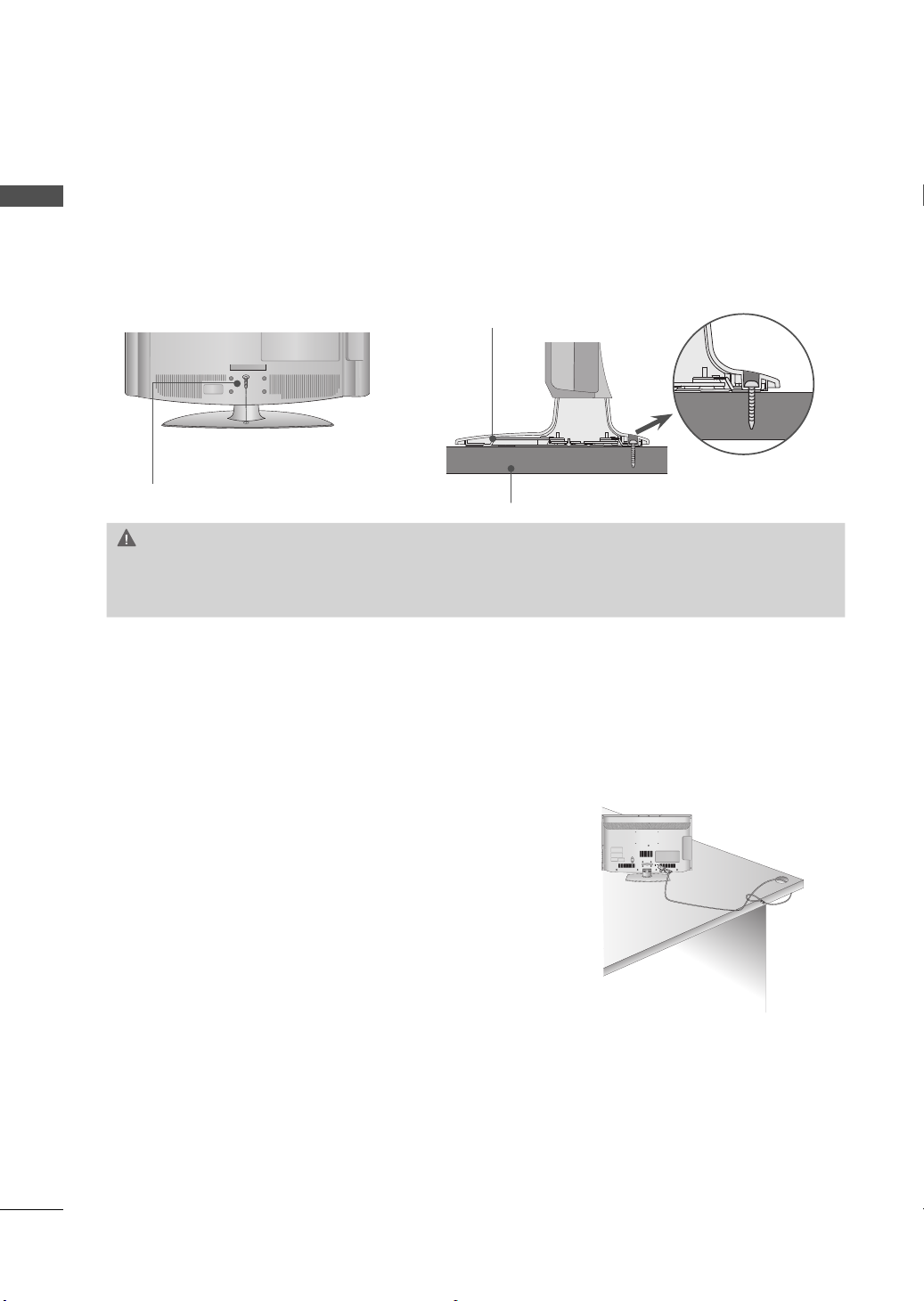
ATTACHING THE TV TO A DESK
(For 32/42LD650, 32LE5500, 32LE7500)
The TV must be attached to a desk so it cannot be pulled in a forward/backward direction, poten-
tially causing injury or damaging the product.
Stand
1-Screw
( provided as parts of the product)
Desk
WARNING
► To prevent TV from falling over, the TV should be securely attached to the floor/wall per installa-
tion instructions. Tipping, shaking, or rocking the machine may cause injury.
24
KENSINGTON SECURITY SYSTEM
ꔛ
This feature is not available for all models.
- The TV is equipped with a Kensington Security System connector on the back panel. Connect the Kensington Security
System cable as shown below.
- For the detailed installation and use of the Kensington Security
System, refer to the user’s guide provided with the Kensington
Security System.
For further information, contact http://www.kensington.com,
the internet homepage of the Kensington company. Kensington
sells security systems for expensive electronic equipment such
as notebook PCs and LCD projectors.
NOTE: The Kensington Security System is an optional accessory.
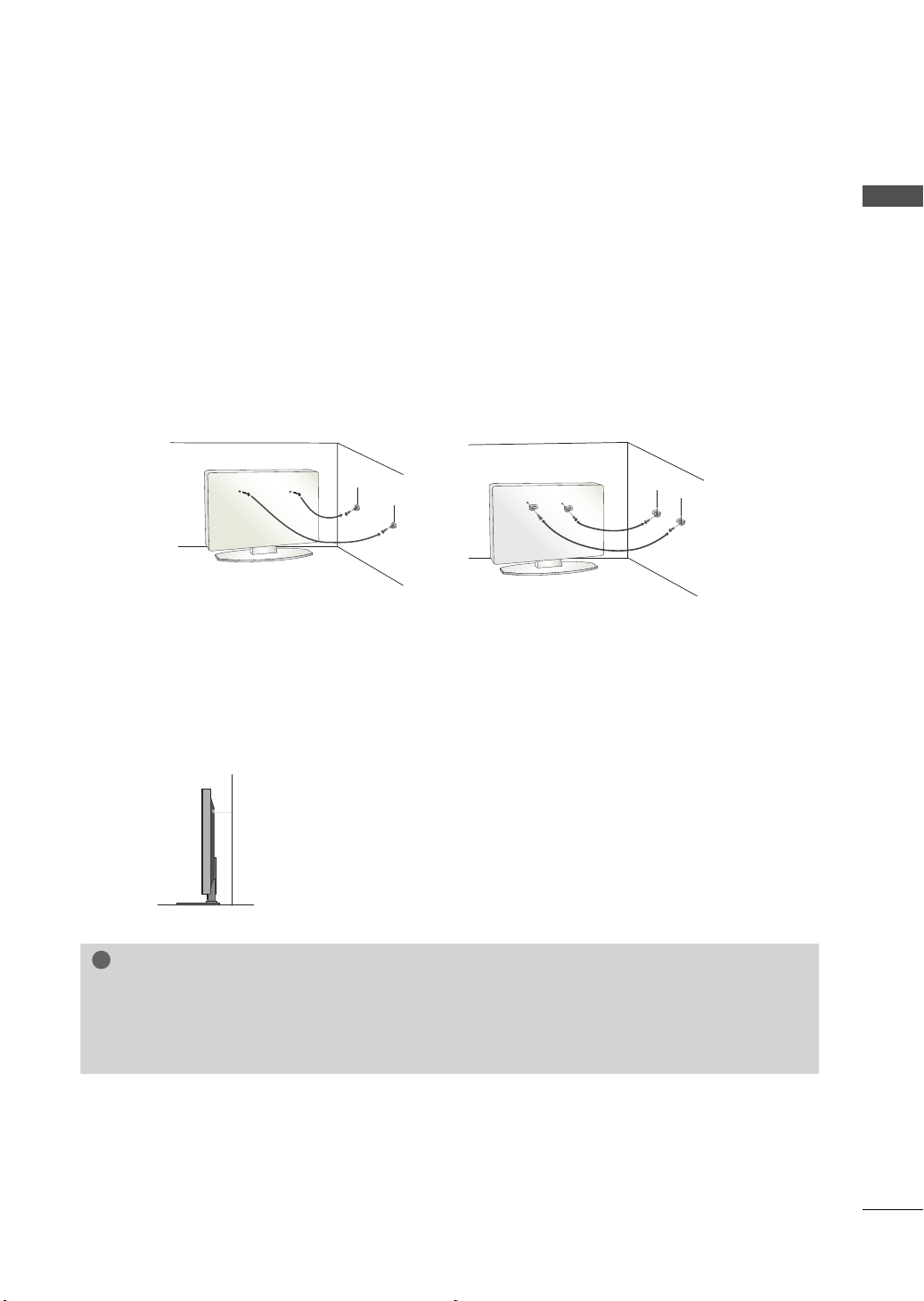
SECURING THE TV TO THE WALL TO PREVENT FALLING
!
WHEN THE TV IS USED ON A STAND
ꔛ
You should purchase necessary components to prevent the TV from tipping over (when not using a
wall mount).
ꔛ
Image shown may differ from your TV.
We recommend that you set up the TV close to a wall so it cannot fall over if pushed backwards.
Additionally, we recommend that the TV be attached to a wall so it cannot be pulled in a forward
direction, potentially causing injury or damaging the product.
Caution: Please make sure that children don’t climb on or hang from the TV.
ꔛ
Insert the eye-bolts (or TV brackets and bolts) to tighten the product to the wall as shown in the
picture.
* If your product has the bolts in the eye-bolts position before inserting the eye-bolts, loosen the
bolts.
* Insert the eye-bolts or TV brackets/bolts and tighten them securely in the upper holes.
Secure the wall brackets with the bolts (sold separately) to the wall. Match the height of the bracket
that is mounted on the wall to the holes in the product.
Ensure the eye-bolts or brackets are tightened securely.
PREPARATION
ꔛ
Use a sturdy rope (sold separately) to tie the product. It is safer to tie the
rope so it becomes horizontal between the wall and the product.
NOTE
► Use a platform or cabinet strong enough and large enough to support the size and weight of
the TV.
► To use the TV safely make sure that the height of the bracket on the wall and the one on the TV are
the same.
25
PREPARATION
ANTENNA/
CABLE IN
ANTENNA/
CABLE IN
H/P
H/P
ꔛ
To prevent damage do not connect to the power outlet until all connections are made between the
devices.
ꔛ
PREPARATION
Image shown may differ from your TV.
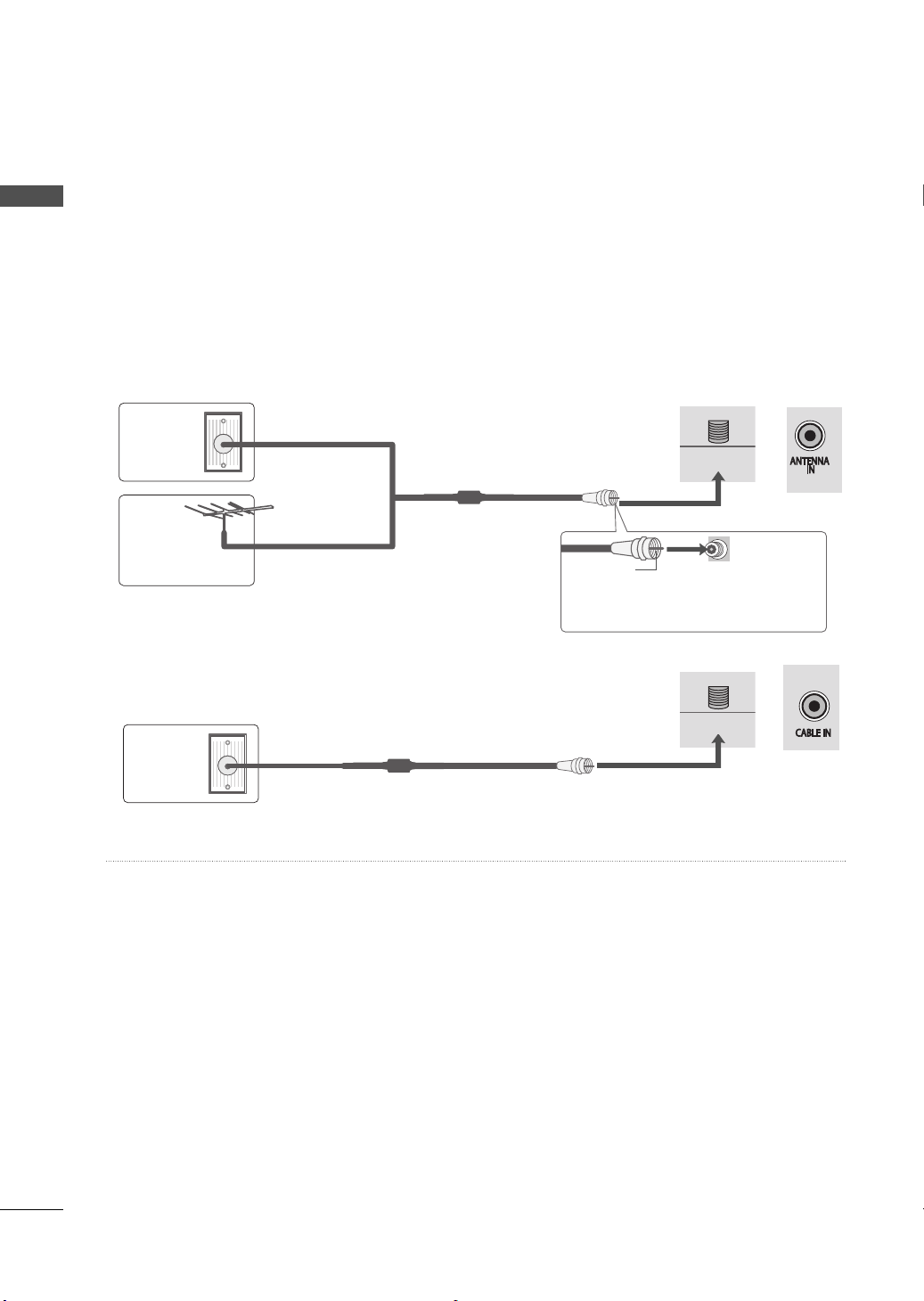
ANTENNA OR CABLE CONNECTION
1. Antenna (Analog)
Wall Antenna Socket or Outdoor Antenna without a Cable Box
Connections.
For optimum picture quality, adjust antenna direction if needed.
Wall
Antenna
Socket
Outdoor
Multi-family Dwellings/Apartments
(Connect to wall antenna socket)
or
RF Coaxial Wire (75 Ω)
Antenna
(VHF, UHF)
2. Cable
Single-family Dwellings /Houses
(Connect to wall jack for outdoor antenna)
Copper Wire
Be careful not to bend the copper wire
when connecting the antenna.
or
Cable TV
Wall Jack
RF Coaxial Wire (75 Ω)
ꔛ
To improve the picture quality in a poor signal area, please purchase a signal amplifier and install
properly.
ꔛ
If the antenna needs to be split for two TV’s, install a 2-Way Signal Splitter.
ꔛ
If the antenna is not installed properly, contact your dealer for assistance.
26
EXTERNAL EQUIPMENT SETUP
RGB IN (PC)
(RGB/DVI)
RS-232C IN
(
CONTROL&SERVICE)
OPTICAL
DIGITAL
/DVI IN
2
3
1
VIDEO
AUDIO
L(MONO)
R
AV IN 1
AUDIO IN
AUDIO OUT
VIDEO
AUDIO
COMPONENT IN
YPBP
R
L R
2
1
Y L RPBP
R
ꔛ
To prevent the equipment damage, never plug in any power cords until you have finished connecting all
equipment.
ꔛ
I
mage shown may differ from your TV.
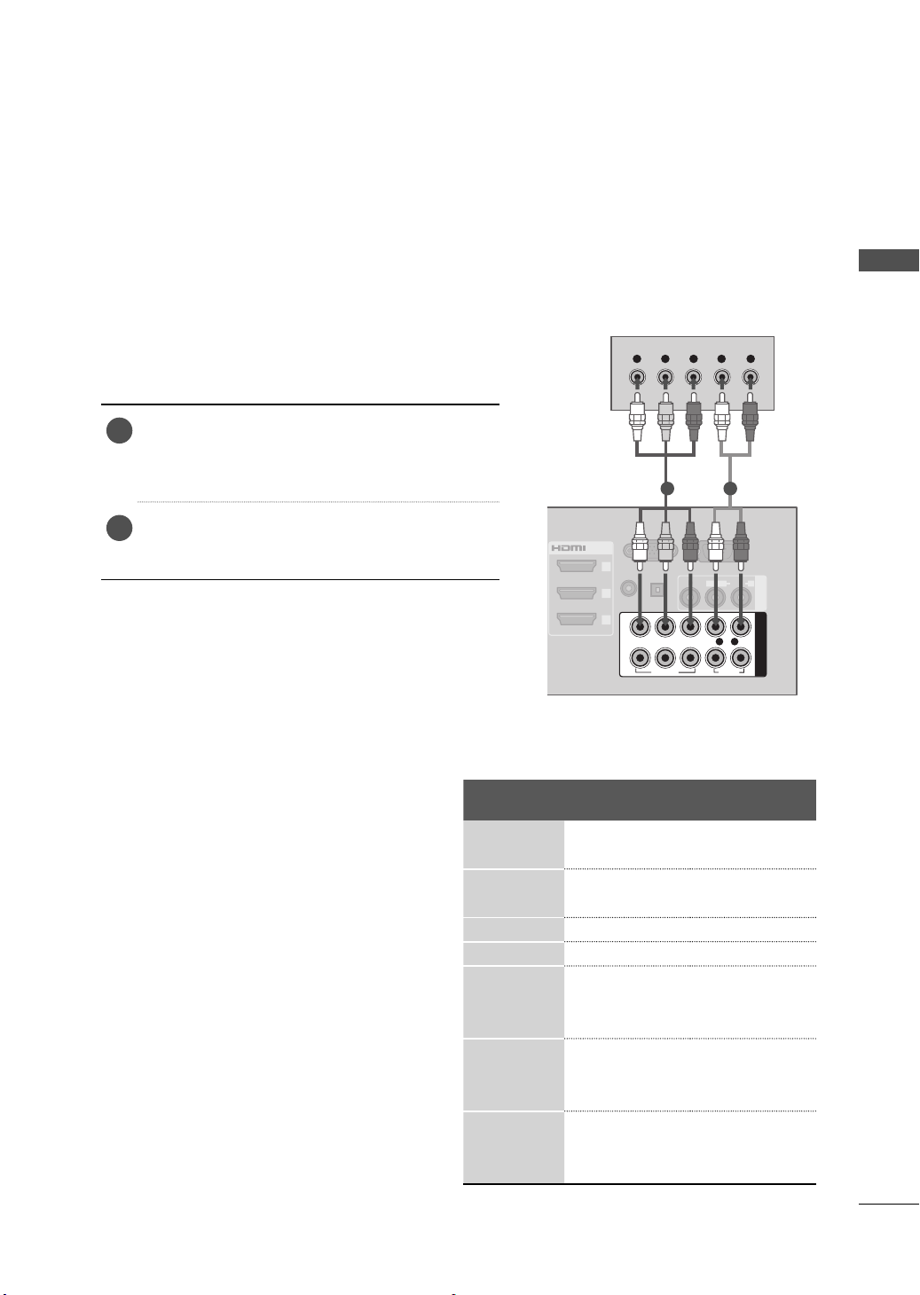
HD RECEIVER SETUP
This TV can receive digital over-the-air/digital cable signals with an external digital set-top box.
However, if you do receive digital signals from a digital set-top box or other digital external device.
Component Connection
1. How to connect
)
Connect the video outputs (Y, P B, PR
1
digital set-top box to the COMPONENT IN
VIDEO 1, 2, or 3* jacks on the TV. Match the
jack colors (Y = green, P
Connect the audio output of the digital set-top
2
box to the COMPONENT IN AUDIO 1, 2, or 3*
jacks on the TV.
2. How to use
ꔛ
Turn on the digital set-top box.
(Refer to the owner’s manual for the digital set-top
box operation.)
ꔛ
Select the Component1, Component2, or
Component3* input source on the TV using the
INPUT button on the remote control.
* Component3: For LED LCD TV
B = blue, and PR = red).
of the
1 2
B/PB, CR/PR
Y, C
Resolution
720x480i
720x480p
Horizontal
Frequency(kHz
15.7
3 59.94
15.75 60.00
31.47 59.94
31.50 60.00
720x576i 15.625 50.00
720x576p 31.25 50.00
44.96 59.94
1280x720p
37.50 50.00
45.00 60.00
33.72 59.94
1920x1080i
28.125 50.00
33.75 60.00
56.25 50.00
1920x1080p
67.432 59.94
67.50 60.00
)
Vertical
Frequency(Hz
EXTERNAL EQUIPMENT SETUP
)
27
EXTERNAL EQUIPMENT SETUP
!
YLR PBP
R
AUDIO / Y P
B
P
R
IN 4
H/P
USB IN 1 USB IN 2
AV IN2
VIDEO / AUDIO
COMPONENT IN3
L R
DVI OUTPUT
AUDIO
RGB IN (PC)
LAN
WIRELESS
CONTROL
RS-232C IN
(
CONTROL&SERVICE)
VIDEO
AUDIO
L(MONO)
R
VIDEO
AUDIO
COMPONENT INAV IN 1
YPBP
R
L R
AUDIO OUT
2
1
/DVI IN
2
3
1
(RGB/DVI)
AUDIO IN
OPTICAL DIGITAL
ꔡ
For LED LCD TV
EXTERNAL EQUIPMENT SETUP
1
2
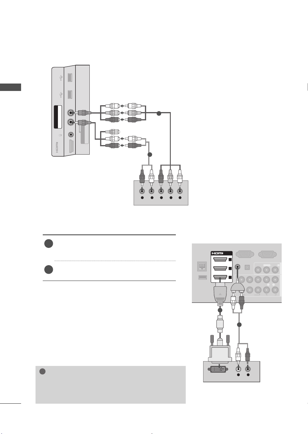
DVI to HDMI Connection
1. How to connect
Connect the DVI output of the digital set-top
1
box to the HDMI/DVI IN 1, 2, or 3* jack on the
TV.
Connect the digital set-top box audio output to
2
the AUDIO IN (RGB/DVI) jack on the TV.
2. How to use
ꔛ
(Refer to the owner’s manual for the digital set-
ꔛ
* HDMI3: For 32/42/47/55LE5500, 42LE5550,
32/42/47/55LE7500, 50/60PK950R,
42/47LE8500, 42/47LX6500
NOTE
► A DVI to HDMI cable or adapter is required for this con-
nection. DVI doesn't support audio, so a separate audio
connection is necessary.
Turn on the digital set-top box.
top box.)
Select the HDMI1, HDMI2, or HDMI3* input source
on the TV using the INPUT
control.
button on the remote
1
2
28
HDMI OUTPUT
RGB IN (PC)
LAN
WIRELESS
CONTROL
(RGB/DVI)
RS-232
(
CONTROL&S
OPTICAL
DIGITAL
VIDEO
L(MONO
VIDEO
A
YPBP
R
L
AUDIO IN
AUDIO OUT
2
1
/DVI IN
2
3
1
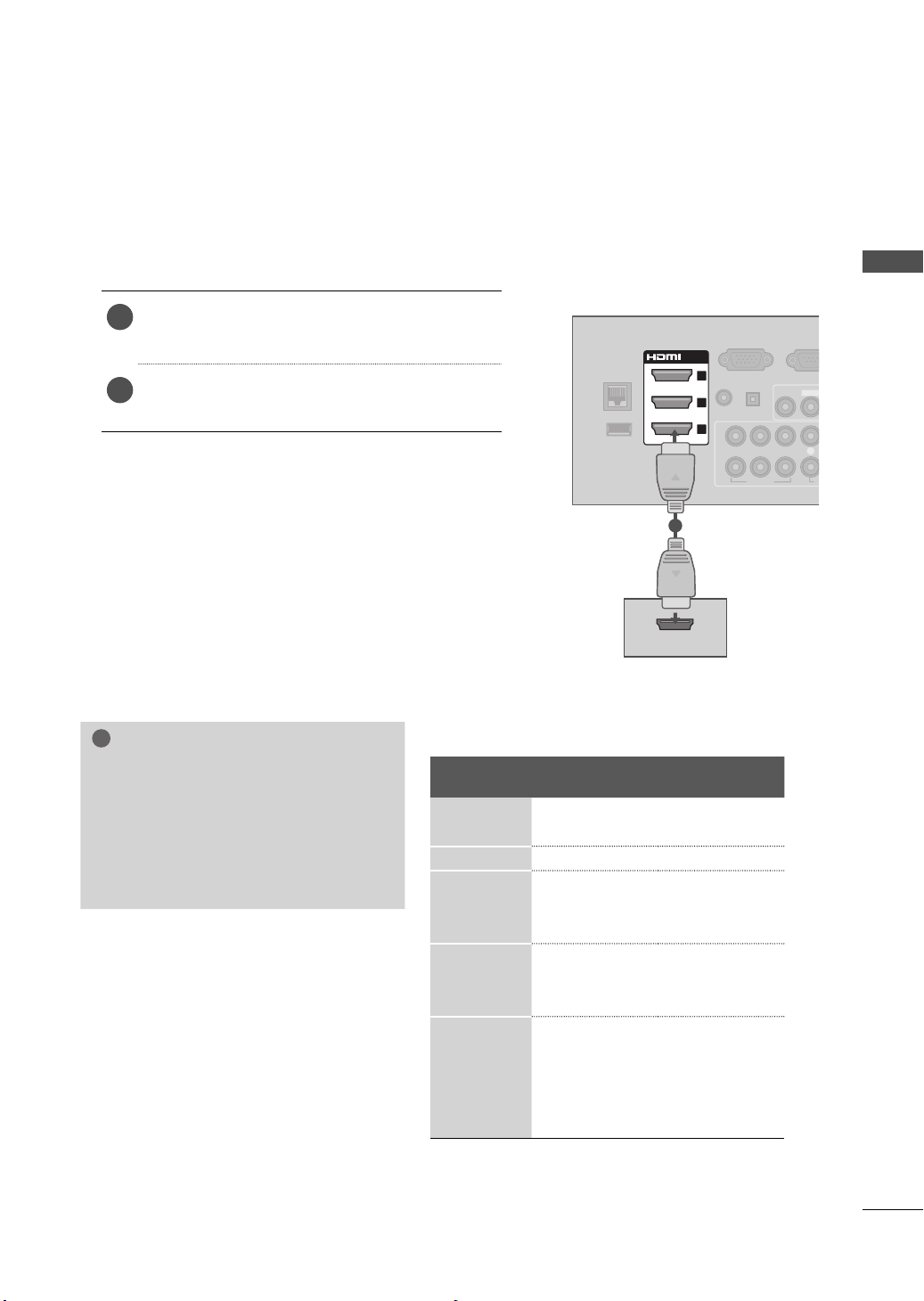
HDMI Connection
!
1. How to connect
Connect the digital set-top box to HDMI/DVI IN
1
1, 2, 3 or 4* jack on the TV.
No separate audio connection is necessary.
2
HDMI supports both audio and video.
2. How to use
ꔛ
Turn on the digital set-top box.
(Refer to the owner’s manual for the digital set-
top box.)
ꔛ
Select the HDMI1, HDMI2, HDMI3, or HDMI4* input
source on the TV using the INPUT
remote control.
* HDMI4: For 32/42/47/55LE5500, 42LE5550,
32/42/47/55LE7500, 50/60PK950R,
42/47LE8500, 42/47LX6500
NOTE
► If an HDMI cable doesn’t support High
Speed HDMI, it can cause flickers or
no screen display. In this case use the
latest cables that support High Speed
HDMI.
► HDMI Audio Supported Format: Dolby
Digital, PCM
button on the
HDMI-DTV
Resolution
720x480p
720x576p 31.25 50.00
1280x720p
1920x1080i
1920x1080p
Horizontal
Frequency(kHz
31
)
.47 59.94
31.50 60.00
44.96 59.94
37.5 50.00
45.00 60.00
33.72 59.94
28.125 50.00
33.75 60.00
27.00 24.00
33.75 30.00
56.25 50.00
67.432 59.94
67.50 60.00
1
Vertical
Frequency(Hz
EXTERNAL EQUIPMENT SETUP
)
29
EXTERNAL EQUIPMENT SETUP
RGB IN (PC)
S
(RGB/DVI)
RS-232C IN
(
CONTROL&SERVICE)
OPTICAL
DIGITAL
/DVI IN
2
3
1
VIDEO
AUDIO
L(MONO)
R
AV IN 1
AUDIO IN
AUDIO OUT
VIDEO
AUDIO
COMPONENT IN
YPBP
R
L R
2
1
Y L RPBP
R
YLR PBP
R
AUDIO / Y PB PR
IN 4
H/P
USB IN 1 USB IN 2
AV IN2
VIDEO / AUDIO
COMPONENT IN3
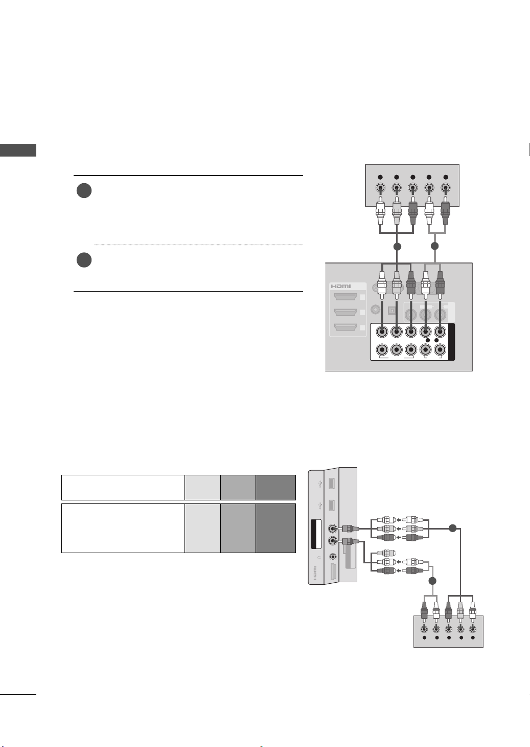
DVD SETUP
Component Connection
EXTERNAL EQUIPMENT SETUP
1. How to connect
Connect the video outputs (Y, P B, PR
1
DVD to the COMPONENT IN VIDEO 1, 2, or 3*
jacks on the TV.
Match the jack colors (Y = green, P
P
R = red
Connect the audio outputs of the DVD to the
2
COMPONENT IN AUDIO 1, 2, or 3* jacks on the
TV.
2. How to use
ꔛ
Turn on the DVD player, insert a DVD.
ꔛ
Select the Component1, Component2, or
Component3* input source on the TV using the
INPUT button on the remote control.
ꔛ
Refer to the DVD player’s manual for operating
instructions.
* Component3: For LED LCD TV
Component Input ports
To get better picture quality, connect a DVD player to
the component input ports as shown below.
)
of the
B = blue, and
)
.
1
2
For LED LCD TV
30
Component ports on the
Video output ports
on DVD player
TV
YPB PR
YPB PR
YB-YR-Y
YCb Cr
YPb Pr
1
2
 Loading...