

LG 31MU97Z Schematic

Internal Use Only
North/Latin America http://aic.lgservice.com
Europe/Africa http://eic.lgservice.com
Asia/Oceania http://biz.lgservice.com
IPS LED MONITOR
SERVICE MANUAL
CHASSIS : LM41C
MODEL : 31MU97 31MU97-BD
CAUTION
BEFORE SERVICING THE CHASSIS,
READ THE SAFETY PRECAUTIONS IN THIS MANUAL.
Printed in KoreaP/NO : MFL63731189 (1408-REV00)

CONTENTS
CONTENTS .............................................................................................. 2
SAFETY PRECAUTIONS ........................................................................ 3
SPECIFICATION ....................................................................................... 4
ADJUSTMENT INSTRUCTION ................................................................ 5
TROUBLE SHOOTING GUIDE ................................................................. 9
BLOCK DIAGRAM .................................................................................. 14
EXPLODED VIEW .................................................................................. 15
SCHEMATIC CIRCUIT DIAGRAM ..............................................................
Only for training and service purposes
- 2 -
LGE Internal Use OnlyCopyright © LG Electronics. Inc. All rights reserved.
To Instrument's
exposed
METALLIC PARTS
Good Earth Ground
such as WATER PIPE,
CONDUIT etc.
AC Volt-meter
SAFETY PRECAUTIONS
IMPORTANT SAFETY NOTICE
Many electrical and mechanical parts in this chassis have special safety-related characteristics. These parts are identified by in the
Schematic Diagram and Exploded View.
It is essential that these special safety parts should be replaced with the same components as recommended in this manual to prevent
Shock, Fire, or other Hazards.
Do not modify the original design without permission of manufacturer.
General Guidance
An isolation Transformer should always be used during the
servicing of a receiver whose chassis is not isolated from the AC
power line. Use a transformer of adequate power rating as this
protects the technician from accidents resulting in personal injury
from electrical shocks.
It will also protect the receiver and it's components from being
damaged by accidental shorts of th e circuitry that may be
inadvertently introduced during the service operation.
If any fuse (or Fusible Resistor) in this TV receiver is blown,
replace it with the specified.
When replacing a high wattage resistor (Oxide Metal Film Resistor,
over 1 W), keep the resistor 10 mm away from PCB.
Keep wires away from high voltage or high temperature parts.
Before returning the receiver to the customer,
always perform an AC leakage current check on the exposed
metallic parts of the cabinet, such as antennas, terminals, etc., to
be sure the set is safe to operate without damage of electrical
shock.
Leakage Current Cold Check(Antenna Cold Check)
With the instrument AC plug removed from AC source, connect an
electrical jumper across the two AC plug prongs. Place the AC
switch in the on position, connect one lead of ohm-meter to the AC
plug prongs tied together and touch other ohm-meter lead in turn to
each exposed metallic parts such as antenna terminals, phone
jacks, etc.
If the exposed metallic part has a return path to the chassis, the
measured resistance should be between 1 MΩ and 5.2 MΩ.
When the exposed metal has no return path to the chassis the
reading must be infinite.
An other abnormality exists that must be corrected before the
receiver is returned to the customer.
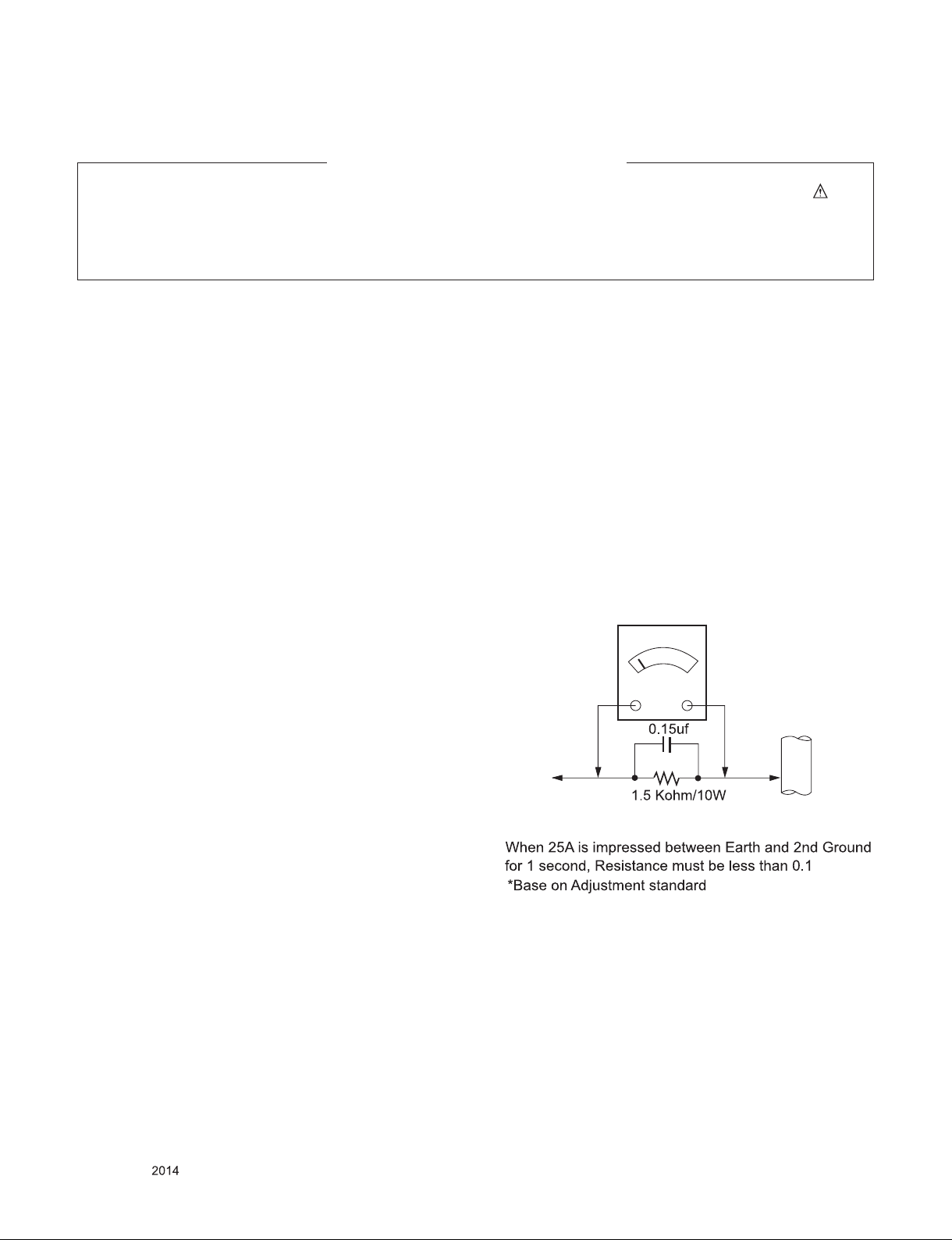
Leakage Current Hot Check (See below Figure)
Plug the AC cord directly into the AC outlet.
Do not use a line Isolation Transformer during this check.
Connect 1.5 K / 10 watt resistor in parallel with a 0.15 uF capacitor
between a known good earth ground (Water Pipe, Conduit, etc.)
and the exposed metallic parts.
Measure the AC voltage across the resistor using AC voltmeter
with 1000 ohms/volt or more sensitivity.
Reverse plug the AC cord into the AC outlet and repeat AC voltage
measurements for each exp ose d metallic par t. Any voltage
measured must not exceed 0.75 volt RMS which is corresponds to
0.5 mA.
In case any measurement is out of the limits specified, there is
possibility of shock hazard and the set must be checked and
repaired before it is returned to the customer.
Leakage Current Hot Check circuit
Only for training and service purposes
- 3 -
LGE Internal Use OnlyCopyright © LG Electronics. Inc. All rights reserved.

SPECIFICATION
NOTE : Specifications and others are subject to change without notice for improvement
1. Module General Specification
No Item Content Remark
1 Customer BRAND
2 User Model Name 31MU97
3 Sale region Refer to Sufx standard
4 Feature 31” LCD MONITOR(UHD)
5 Chassis Name LM41C
6 General Scope External SW &Adj.
◄, ►,▲,▼,⊙(push)
Function PBP, Picture Mode Ratio, Gamma Calibration, ECO,
Six Color, 5W speaker x 2, TCP, Screen split, USB
hub(USB3.0 x 3)
7 Power Code Length : 1.55±0.05 M
Shape : Wall-out
Color : Black
Weight : 0.16kg
8 Cable USB Length : 1.5m
Shape : A-B
Color : Black
Pin
Weight : 0.1kg
HDMI Length : 1.8m
Shape : Detachable Type
Color : black
Weight : 0.11kg
DP to Mini DP Length : 1.8m
Shape : Detachable Type
Color : black
Weight : 0.105kg
9 Power Input: AC100~240V 50~60Hz,1.5A Max
Output: DC 19V 6.2A
120W PSU
Weight : 0.365kg
10 Mechanical
(ass’y)
11 Manual ass’y 0.086kg Refer to BOM
12 Handling guide 0.006kg Refer to BOM
13 Factory calibration report 0.006kg Refer to BOM
14 Applying module list P/No Specication
Stand body 1kg AAN750088
Stand base 0.9kg AAN750089
Cable holder 0.008kg AGF775993
Screw 0.004kg (1ass’y : screw 2ea) AGF767026
EAJ62968501 LM310UH1-SLA2
.
5-way joystick switch
Refer to Sufx standard and power cord
table
P/N : EAD61273120
P/N : EAD00926103
P/N : EAD63127601
EAY63288601
Only for training and service purposes
- 4 -
LGE Internal Use OnlyCopyright © LG Electronics. Inc. All rights reserved.
ADJUSTMENT INSTRUCTION
1. Application Range
This document is applied to LM41C chassis 31” LCD Monitor
which is manufactured in Monitor Factory or is produced on
the basis of this data.
2. Designation
(1) Th e ad justm ent is accord ing to the order whic h is
designated and which must be followed, according to the
plan which can be changed only on agreeing.
(2) Power Adjustment: Free Voltage
(3) Magnetic Field Condition: Nil.
(4) Input signal Unit: Product Specification Standard
(5) Reserve after operation: Above 5 Minutes (Heat Run)
Temperature : at 25 °C ± 5 °C
Relative humidity : 65 % ± 10 %
Input voltage : 100 V~ 240 V, 50/60Hz
(6) Adju stment equ ipments: Color Ana lyzer (CA-210 or
CA-110), DDC Adjustment Jig equipment,
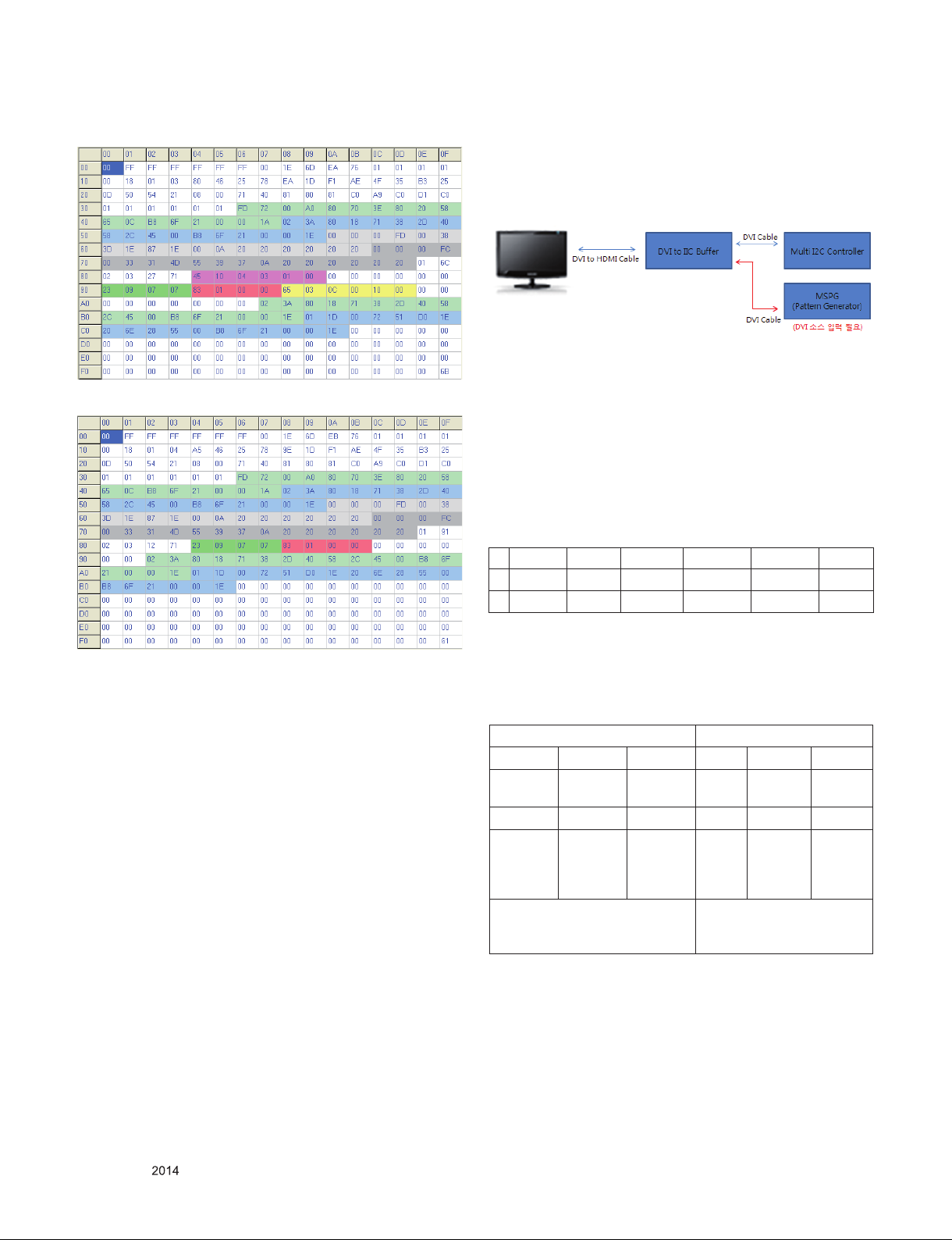
3. Main PCB check process
* APC - After Manual-Insult, executing APC
3.1. ADC Process
(1) 31MU97 doesn’t need ADC process because it has only
digital input like DisplayPort and HDMI.
3.2. EDID Process
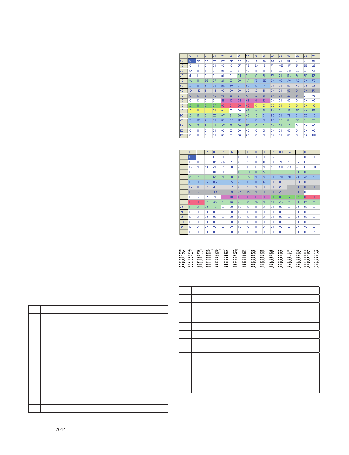
3.2.1. EDID Download
F/W includes default EDID for All input ports, aging on Mode If
AC ON, default EDID is automatically loaded to EEPROM.
Update serial number in EDID of HDMI1.
- EDID Ver. 1.3 FOR HDMI1/2 Data ( 256 Bytes )
- EDID Ver. 1.4 FOR DP/MiniDP Data ( 256 Bytes )
- DisplayID FOR DP/MiniDP Data ( 128 Bytes )
* Caution : Never connect HDMI Cable when execute NVRAM
Init and AC On at first for downloading HDMI EDID
automatically.
** Protocol : DDC 2AB
3.2.2. Single EDID Information
(do not support Thunderbolt)
No Item Content 16 Data
1 Manufacturer ID GSM 1E 6D
2 Product ID HDMI : 30438
Display Port : 30439
Thunderbolt : 30441
3 Year 2015 TBD
4 Version 1 1
5 Revision HDMI : 3
DP : 4
6 Serial Number * *
7 Week ** **
8 Model Name 31MU97 --
9 Check Sum **** ****
10 Special Item
Only for training and service purposes
E676
E776
E976
HDMI : 3
DP : 4
3.2.3. PBP EDID Information
No Item Content 16 Data
1 Manufacturer ID GSM 1E 6D
2 Product ID HDMI1/2 : 30442
DP/MiniDP : 30443
Thunderbolt : 30444
3 Year 2015 TBD
4 Version 1 1
5 Revision HDMI : 3
DP : 4
6 Serial Number * *
7 Week ** **
8 Model Name 31MU97 --
9 Check Sum **** ****
10 Special Item
- 5 -
LGE Internal Use OnlyCopyright © LG Electronics. Inc. All rights reserved.
EA76
EB76
EC76
HDMI : 3
DP : 4
- EDID Ver. 1.3 FOR HDMI1/2 PBP Data ( 256 Bytes )
- EDID Ver. 1.4 FOR DP/MiniDP PBP Data ( 256 Bytes )
4. Total Assembly line process
4.1. Write HDCP Key
- Write HDCP Key into EEPROM by using DDC2AB protocol
& HDCP Adjustment Jig equipment.
- If error is occurred, try to write again.
4.2. White balance adjustment
- Adju st PRESET Warm(650 0K) Col or coordinates an d
Gamma calibration .
■ Input Gamma calibration Pattern (R,G,B, Grey 20 )
■ Set as Warm(6500K) by commanding COLOR_MODE_
CHANGE Command code.
■ Gamma calibration and verify
Start - Read Elapsed time - Measure - Verify - Output
Report - End
■ Warm(6500K) Color adjustment.
Adjust to meet x/y color coordinate as below.
2~4 min 4~8min 8~10min 10~25min 25~40min 40min~
x 0.318 0.318 0.317 0.316 0.314 0.313
y 0.339 0.338 0.337 0.334 0.332 0.329
3.3. Function Check
3.3.1. Check Screen
■ Check input and signal items. (cf. work instructions)
1. HDMI1/2 (4096 x 2160 @24Hz)
2. DisplayPort1.2 (4096 x 2160 @60Hz) - using PC
* Save Warm(6500K) Color by commanding COLOR SAVE
Command code.
Insert HDMI Jack which is connected with PC for White
Balance or equivalent device.
-> Total Assembl y line shoul d check whether the co lor
coordinate(x,y) data refer to below table were meet or not.
Color Temperature Luminance(cd/m2)
Cool Medium Warm Cool Medium Warm
9,300k 8,000k 6,500k Min :
170
°K °K °K
X=0.283
(±0.03)
Y=0.298
(±0.03)
*Note : x,y coordinates are drifted about 0.007 after 30 mins
X=0.295
(±0.03)
Y=0.305
(±0.03)
<Test Signal>
Inner pattern
(255gray,100IRE)
heat-run. So checking color coordinate within 5-min at
total assembly line, consider x,y coordinates might be
up to 0.007 than x,y target of each color temperature.
X=0.313
(±0.03)
Y=0.329
(±0.03)
Min :
200
<Test Signal>
Inner pattern
(255gray,100IRE)
Min :
260
Only for training and service purposes
- 6 -
LGE Internal Use OnlyCopyright © LG Electronics. Inc. All rights reserved.

* Note : Manual W/B process
1) Power off => Power on
( ‘<-’ 3 times, ‘->’ 1 time and push ‘◎’)
2) and push the “<-” or “->”.
3) In Service Menu.
* When doing Adjustment, Please make circumstance as
below.
5. Signal composition for adjustment
5.1. I2C (100K BPS)
5.2. COMMUNICATION START
# Until ACK BIT goes LOW, Repeat it.
5.3. Command form.
Command form use DDC2AB standard communication
protocol.
a. LEN : DATA BYTE number to send.
b. CMD : Command language that monitor executes.
c. VAL : FOS DATA
d. CS : Dada’s CHECHSUM that transmit
e. DELAY : 50MS
f. A : Acknowledge
4.3. DPM Operation check
■ Measurement Condition: 100 ~ 240 V @ 50/60Hz
(1) Set Input to DVI-D, DisplayPort, HDMI1, HDMI2
(2) Turn off the source device.
(3) Check DPM operation refer to the below table.
Operating
Condition
Sleep
mode
Off
mode
Sync (H/V)
or Video
Off/Off Off White
- - Off 0W Mech.
EUT
(MSPG6100)
LED
(SET)
blinking
Off 0.5W DC
Wattage
(W)
1.2W
Switch off
Switch Off
5.4. Screen adjust command (LENGTH = 84)
Only for training and service purposes
- 7 -
LGE Internal Use OnlyCopyright © LG Electronics. Inc. All rights reserved.

5.5. EEPROM Data Write
5.5.1 Siganl TABLE
LEN : 84h+Bytes
CMD : E8h
ADH : E2PROM Slave Address(A0,A2,A4,A6,A8,AA,AC,AE),
Not 00h(Reserved by Buffer To EEPROM)
ADL : E2PROM Sub Address(00~FF)
Data : Write data
Delay : 20ms
5.5.2. Command Set
No.
Adjustment
contents
1 EEP R O M
WRITE
2 (84+n) n-byte Write
* Use
■ FOS Default write :
<14mode data> write
SyncFlags,HPeriodH, HPeriodL, VtotalH,VtotalL,
SrcHTotalH, SrcHTotalL
SrcHStartH, SrcHStartL, SrcVStartH,SrcVStartL,
HsyncPhase
■ Temporary Data write: Write to particular address of
EEPROM.
CMD(hex) LEN Explanation
E8 94 16-Byte Write
5.6. E2PROM Data Read
5.6.1. Signal TABLE
5.6.2. COMMAND SET
No. Adjustment
contents
1 EEPROM
READ
2 80 0-Page 80~FF Read
3 A2 0 1-Page 0~7F Read
4 80 1-Page 80~FF Read
5 A4 0 2-Page 0~7F Read
6 80 2-Page 80~FF Read
7 A6 0 3-Page 0~7F Read
8 80 3-Page 80~FF Read
9 A8 0 4-Page 0~7F Read
10 80 4-Page 80~FF Read
11 AA 0 5-Page 0~7F Read
12 80 5-Page 80~FF Read
13 AC 0 6-Page 0~7F Read
14 80 6-Page 80~FF Read
15 AE 0 7-Page 0~7F Read
16 80 7-Page 80~FF Read
CMD
ADH
ADL
(hex)
(hex)
E7 A0 0 0-Page 0~7F Read
Explanation
(hex)
Only for training and service purposes
5.6.3. Use
Read E2PROM’s specic area as unit of 128(80h)-byte. (84h)
5.6.4 EDID Write
EEPROM access by using DDC2B protocol
■ 1-Byte write
L : 0x00~0x7F
D : data
■ 8-byte write
L : 0x00,0x10,….0x70
5.6.5. EDID Read
- DDC2B Command.(A0/A1)
- 128 Byte transfer of EDID Buffer of MICOM
- 8 -
LGE Internal Use OnlyCopyright © LG Electronics. Inc. All rights reserved.

TROUBLE SHOOTING GUIDE
1. No Power (Power Board)
Is Input signal timing
and format in spec?
Y
Does DP Cable have no prob lem ?
Y
Does DP Jack (JK100) have no
problem ??
Y
Change Main Scaler (IC100).
N
Change DP jack.
Only for training and service purposes
- 9 -
LGE Internal Use OnlyCopyright © LG Electronics. Inc. All rights reserved.

2. No Power (Main Board)
Is 3.3V at IC702 output
voltage?
Y
Is 3.3V at IC706 output
voltage?
Y
Is 1.2V at IC701 output
voltage?
Y
Is 1.2V at IC707 o utput
voltage?
Y
Is 112MHz of X200/X300
frequency ?
N
Change IC702 and check
again.
N
Change IC706 and check
again.
N
Change IC701 and check
again.
N
Change IC507 and check
again.
N
Change X200/X300 and
check again.
Y
Change IC205 Serial flash
memory
DC-DC converter block
Crystal
DC-DC converter block
Crystal
Only for training and service purposes
- 10 -
LGE Internal Use OnlyCopyright © LG Electronics. Inc. All rights reserved.
 Loading...