

LG 29FX6AM Schematic

- 2 -
CONTENTS
CONTENTS .............................................................................................. 2
SAFETY PRECAUTIONS ..........................................................................3
CONTROL DESCRIPTIONS .................................................................... 4
SPECIFICATIONS .................................................................................... 7
ADJUSTMENT INSTRUCTIONS ............................................................. 8
TROUBLE SHOOTING .......................................................................... 17
PRINTED CIRCUIT BOARD ....................................................................20
BLOCK DIAGRAM ................................................................................. 24
EXPLODED VIEW .................................................................................. 28
SVC. Sheet ..................................................................................................
Copyright©2008 LG Electronics.Inc. All right reserved.
Only for training and service purposes.
LGE Internal Use Only
- 3 -
SAFETY PRECAUTIONS
Many electrical and mechanical parts in this chassis have special safety-related characteristics. These parts are identified by in
the Schematic Diagram and Replacement Parts List.
It is essential that these special safety parts should be replaced with the same components as recommended in this manual to
prevent X-RADIATION, Shock, Fire, or other Hazards.
Do not modify the original design without permission of manufacturer.
General Guidance
An Isolation Transformer should always be used during
the servicing of a receiver whose chassis is not isolated from
the AC power line. Use a transformer of adequate power rating
as this protects the technician from accidents resulting in
personal injury from electrical shocks.
It will also protect the receiver and it's components from being
damaged by accidental shorts of the circuitry that may be
inadvertently introduced during the service operation.
If any fuse (or Fusible Resistor) in this TV receiver is blown,
replace it with the specified.
When replacing a high wattage resistor (Oxide Metal Film
Resistor, over 1W), keep the resistor 10mm away from PCB.
Keep wires away from high voltage or high temperature parts.
Due to high vacuum and large surface area of picture tube,
extreme care should be used in handling the Picture Tube.
Do not lift the Picture tube by it's Neck.
X-RAY Radiation
Warning:
To determine the presence of high voltage, use an accurate
high impedance HV meter.
Adjust brightness, color, contrast controls to minimum.
Measure the high voltage.
The meter reading should indicate
23.5 ± 1.5KV: 14-19 inch, 26 ± 1.5KV: 19-21 inch,
29.0 ± 1.5KV: 25-29 inch, 30.0 ± 1.5KV: 32 inch
If the meter indication is out of tolerance, immediate service
and correction is required to prevent the possibility of
premature component failure.
Before returning the receiver to the customer,
always perform an AC leakage current check on the
exposed metallic parts of the cabinet, such as antennas,
terminals, etc., to be sure the set is safe to operate without
damage of electrical shock.
Leakage Current Cold Check(Antenna Cold Check)
With the instrument AC plug removed from AC source,
connect an electrical jumper across the two AC plug prongs.
Place the AC switch in the on position, connect one lead of
ohm-meter to the AC plug prongs tied together and touch other
ohm-meter lead in turn to each exposed metallic parts such as
antenna terminals, phone jacks, etc.
If the exposed metallic part has a return path to the chassis, the
measured resistance should be between 1MΩ and 5.2MΩ.
When the exposed metal has no return path to the chassis the
reading must be infinite.
An other abnormality exists that must be corrected before the
receiver is returned to the customer.
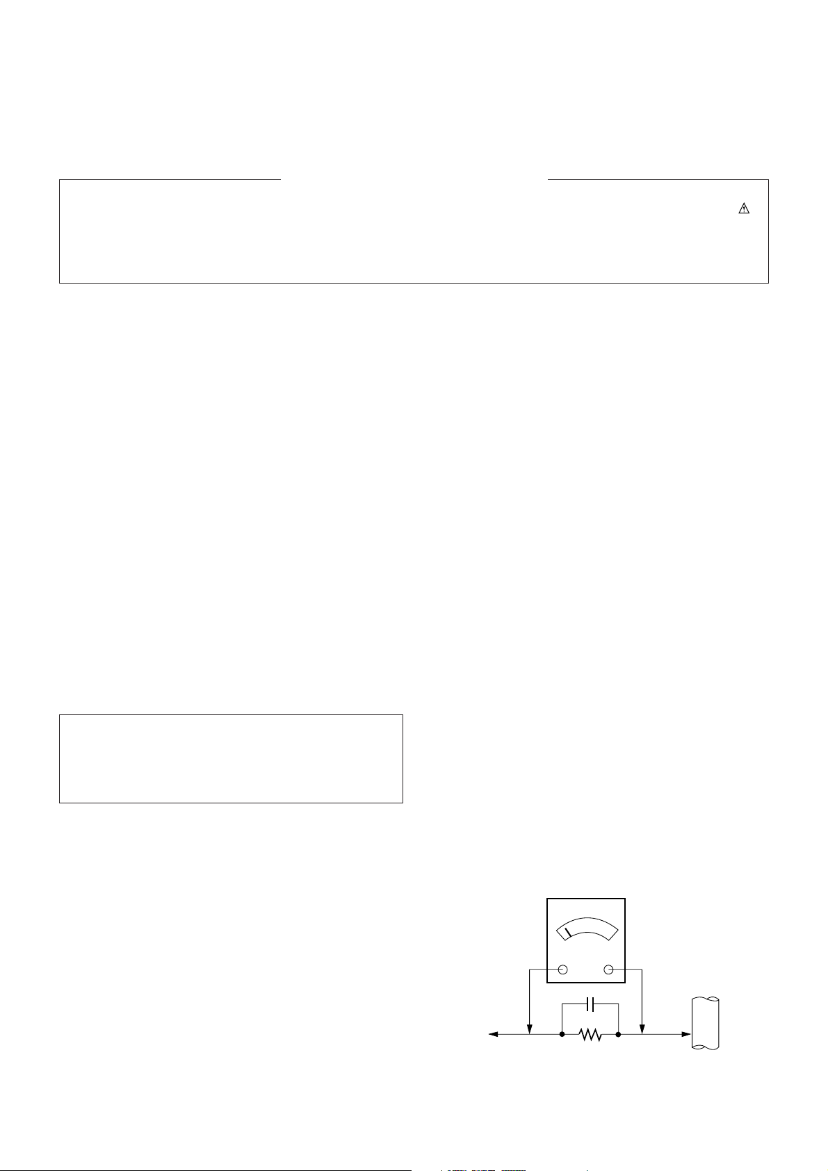
Leakage Current Hot Check (See below Figure)
Plug the AC cord directly into the AC outlet.
Do not use a line Isolation Transformer during this check.
Connect 1.5K/10watt resistor in parallel with a 0.15uF capacitor
between a known good earth ground (Water Pipe, Conduit, etc.)
and the exposed metallic parts.
Measure the AC voltage across the resistor using AC
voltmeter with 1000 ohms/volt or more sensitivity.
Reverse plug the AC cord into the AC outlet and repeat AC
voltage measurements for each exposed metallic part. Any
voltage measured must not exceed 0.75 volt RMS which is
corresponds to 0.5mA.
In case any measurement is out of the limits specified, there is
possibility of shock hazard and the set must be checked and
repaired before it is returned to the customer.
Leakage Current Hot Check circuit
The source of X-RAY RADIATION in this TV receiver is the
High Voltage Section and the Picture Tube.
For continued X-RAY RADIATION protection, the
replacement tube must be the same type tube as specified in
the Replacement Parts List.
IMPORTANT SAFETY NOTICE
0.15uF
Copyright©2008 LG Electronics.Inc. All right reserved.
Only for training and service purposes.
LGE Internal Use Only
AC Volt-meter
To Instrument’s
exposed
METALLIC PARTS
Good Earth Ground
such as WATER PIPE,
CONDUIT etc.
1.5 Kohm/10W
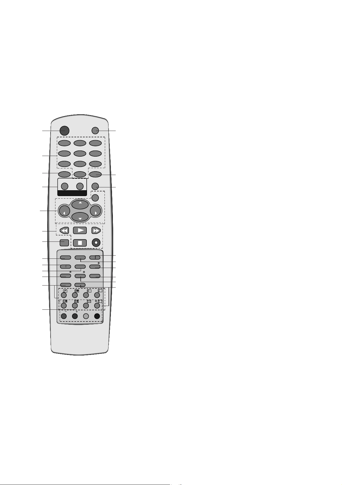
All the functions can be controlled with the remote control handset.
Some functions can also be adjusted with the buttons on the front
panel of the set.
Remote control handset
Before you use the remote control handset, please install the batteries. See the next page.
1. POWER
switches the set on from standby or off to standby.
2. NUMBER BUTTONS
switches the set on from standby or directly select a number.
3. ARC (Aspect Ratio Control)
changes the picture format.
4. TURBO PICTURE BUTTON / SOUND BUTTON (option)
selects Turbo picture/sound.
5.
D / E
(Programme Up/Down)
selects a programme or a menu item.
switches the set on from standby.
F / G
(Volume Up/Down)
adjusts the volume.
adjusts menu settings.
OK
accepts your selection or displays the current mode.
6.
VCR BUTTONS (option)
control a LG video cassette recorder.
7.
I/II
selects the language during dual language broadcast.
selects the sound output (option).
8. PSM (Picture Status Memory)
recalls your preferred picture setting.
9.
SLEEP
sets the sleep timer.
10.
MAIN STILL/
*
(or STILL)
freezes motion of the picture.
11. TELETEXT BUTTONS (option)
These buttons are used for teletext.
For further details, see the ‘Teletext’ section.
12. MUTE
switches the sound on or off.
13. TV/AV
selects TV or AV mode.
switches the set on from standby.
( With TELETEXT)
( With PIP)
OK
PR
VOL
PR
VOL
PLAY
FAVOURITE
STOP
REC
REW
FF
I/II SSM LIST
PSM
SLEEP
MAIN STILL/
Q.VIEW
?
MIX
TIME
SWAP
INPUT
REVEAL MODE
SIZE
STILL
UPDATE
i
M
0
ARC
TV/AV
MENU
PICTURE
SOUND
1
2 3
4
5 6
7
8 9
POWER
MUTE
TEXT
PR
PR
T U R B O
EYE/
INDEX/
PIP
1
2
4
3
5
6
21
7
9
12
13
14
15
18
17
16
19
20
10
8
10
11
- 4 -
CONTROL DESCRIPTIONS
Copyright©2008 LG Electronics.Inc. All right
reserved.
LGE Internal Use Only
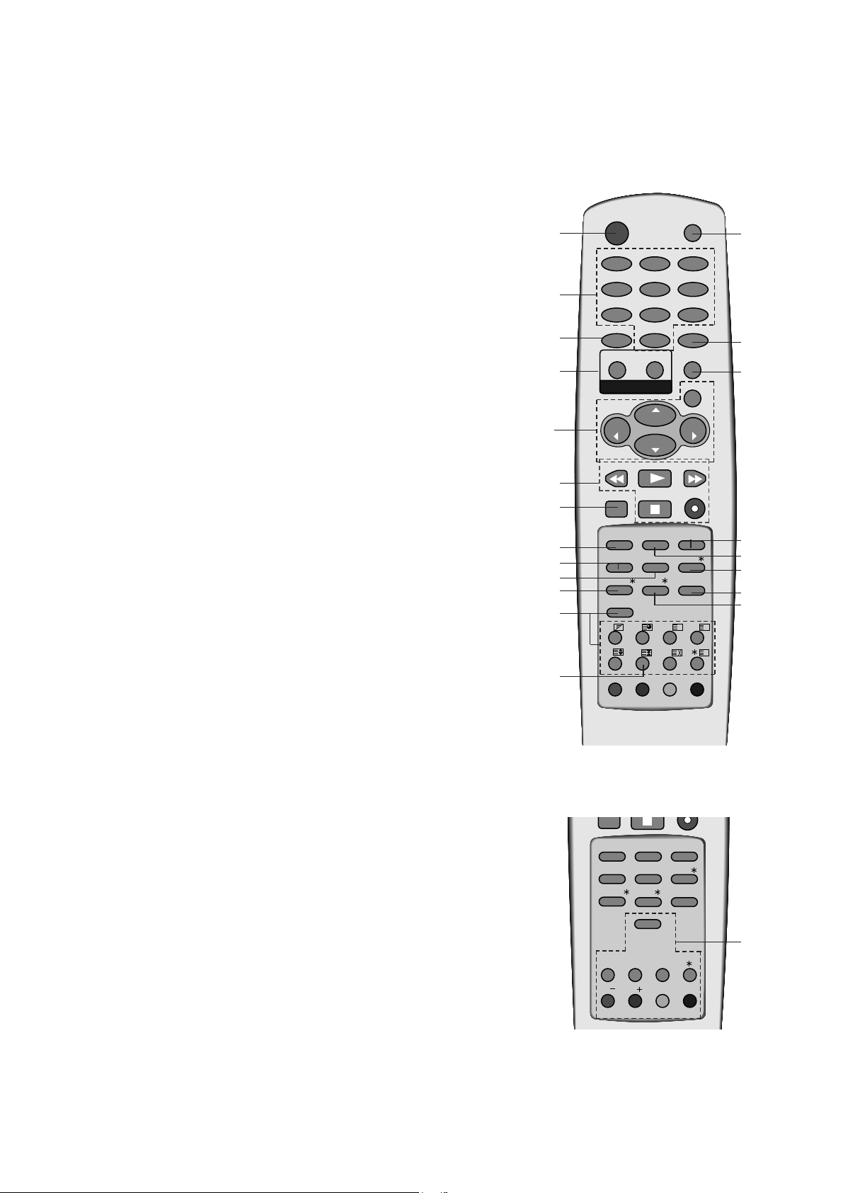
- 5 -
14.
MENU
selects a menu.
15. LIST
displays the programme table.
16. SSM (Sound Status Memory)
recalls your preferred sound setting.
17.
EYE/*(option)
switches the eye function on or off.
18. Q.VIEW
returns to the previously viewed programme.
19. INDEX
/
*
(option)
switches FRONT DISPLAY on or off.
20.
PIP BUTTONS (option)
PIP
switches the sub picture on or off.
PR +/-
selects a programme for the sub picture.
SWAP
alternates between main and sub picture.
INPUT
selects the input mode for the sub picture.
SIZE
adjusts the sub picture size.
STILL
freezes motion of the sub picture.
POSITION
relocates the sub picture in clockwise direction.
21. FAVOURITE
selects a favourite programme.
*
: No function
COLOURED BUTTONS : These buttons are used for teletext (only
TELETEXT models) or programme edit.
I/II SSM LIST
PSM
SLEEP
Q.VIEW
SWAP
INPUT
SIZE
STILL
UPDATE
PR
PR
EYE/
INDEX/
PIP
MAIN STILL/
1
2
4
3
5
6
21
7
9
12
13
14
15
18
17
16
19
20
8
11
10
10
(With TELETEXT / Without PIP)
(Without TELETEXT / With PIP)
Copyright©2008 LG Electronics.Inc. All right reserved.
Only for training and service purposes.
LGE Internal Use Only
POWER
1
4
7
ARC
SOUND
T U R B O
VOL
REW
FAVOURITE
2 3
5 6
8 9
0
PICTURE
PR
PR
PLAY
STOP
MUTE
TV/AV
MENU
OK
VOL
FF
REC
I/II SSM LIST
PSM
SLEEP
INDEX/
MAIN STILL/
TEXT
MIX
TIME
REVEAL MODE
SIZE
STILL
UPDATE
EYE/
Q.VIEW
?
M
i
- 6 -
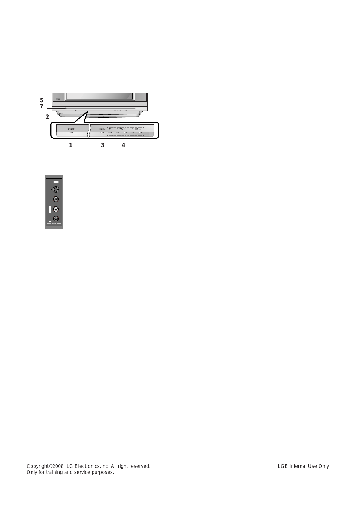
1. MAIN POWER (ON/OFF)
switches the set on or off.
2. POWER/STANDBY INDICATOR
illuminates brightly when the set is in standby
mode.
dims when the set is switched on.
3. MENU
selects a menu.
4. OK
accepts your selection or displays the current
mode.
FF / GG
(Volume Down/Up)
adjusts the volume.
adjusts menu settings.
DD / EE
(Programme Up/Down)
selects a programme or a menu item.
switches the set on from standby.
5. REMOTE CONTROL SENSOR
6. AUDIO/VIDEO IN SOCKETS (AV IN3)
Connect the audio/video out sockets of external equipment to these sockets.
S-VIDEO/AUDIO IN SOCKETS (S-AV)
Connect the video out socket of an S-VIDEO
VCR to the S-VIDEO socket.
Connect the audio out sockets of the S-VIDEO
VCR to the audio sockets as in AV IN3.
7. EYE (option)
adjusts picture according to the surrounding
conditions.
8. HEADPHONE SOCKET (option)
Connect the headphone plug to this socket.
Front panel
Side panel
S-VIDEO
VIDEO
L/MONO RAUDIO
AV IN3
6
@@@@@@@@e?
@@@@@@@@e?
@@h?
@@h?
@@h?
@@h?
@@h?
@@h?
@@@@@@@@e?@@@@@@@@?e@@@@@@@@e?@@@@@@@@?e@@@@@@@@e?@@@@@@@@?e@@@@@@@@e?
@@@@@@@@e?@@@@@@@@?e@@@@@@@@e?@@@@@@@@?e@@@@@@@@e?@@@@@@@@?e@@@@@@@@e?
@@@@@@@@
@@@@@@@@
@@
@@
@@
@@
@@
@@
@@
@@
@@
@@
@@
@@
@@
@@
@@
@@
@@
@@
@@
@@
@@
@@
@@
@@
@@
@@
@@
@@
@@
@@
@@
@@
@@
@@
@@
@@
@@
@@
@@
@@
@@
@@
@@
@@
@@
@@
@@
@@
@@
@@
@@
@@
@@
@@
@@
@@
@@
@@
@@
@@
@@
@@
@@
@@
@@
@@
@@
@@
@@
@@
@@
@@
@@
@@
@@
@@
@@
@@
@@
@@
@@
@@
@@
@@
@@
@@
@@
@@
@@
@@
@@
@@
@@
@@
@@
@@
@@
@@
@@
@@
@@
@@
@@
@@
@@
@@
@@
@@
@@
@@
@@
@@
@@
@@
@@
@@
@@
@@
@@
@@
@@
@@
@@
@@
@@
@@
@@
@@
@@
@@
@@
@@
@@
@@
@@
@@
@@
@@
@@
@@
@@
@@
@@
@@
@@
@@
@@
@@
@@
@@
@@
@@
@@
@@
@@
@@
@@
@@
@@
@@
@@
@@
@@
@@
@@
@@
@@
@@
@@
@@
@@
@@
@@
@@
@@
@@
@@
@@
@@
@@
@@
@@
?@@
?@@
?@@
?@@
?@@
?@@
?@@@@@@@@
?@@@@@@@@
?@@@@@@@@?e@@@@@@@@e?@@@@@@@@?e@@@@@@@@e?@@@@@@@@?e@@@@@@@@e?@@@@@@@@
?@@@@@@@@?e@@@@@@@@e?@@@@@@@@?e@@@@@@@@e?@@@@@@@@?e@@@@@@@@e?@@@@@@@@
@@g
@@g
@@g
@@g
@@g
@@g
@@@@@@@@
@@@@@@@@
@@
@@
@@
@@
@@
@@
@@
@@
@@
@@
@@
@@
@@
@@
@@
@@
@@
@@
@@
@@
@@
@@
@@
@@
@@
@@
@@
@@
@@
@@
@@
@@
@@
@@
@@
@@
@@
@@
@@
@@
@@
@@
@@
@@
@@
@@
@@
@@
@@
@@
@@
@@
@@
@@
@@
@@
@@
@@
@@
@@
@@
@@
@@
@@
@@
@@
@@
@@
@@
@@
@@
@@
@@
@@
@@
@@
@@
@@
@@
@@
@@
@@
@@
@@
@@
@@
@@
@@
@@
@@
@@
@@
@@
@@
@@
@@
@@
@@
@@
@@
@@
@@
@@
@@
@@
@@
@@
@@
@@
@@
@@
@@
@@
@@
@@
@@
@@
@@
@@
@@
@@
@@
@@
@@
@@
@@
@@
@@
@@
@@
@@
@@
@@
@@
@@
@@
@@
@@
@@
@@
@@
@@
@@
@@
@@
@@
@@
@@
@@
@@
@@
@@
@@
@@
@@
@@
@@
@@
@@
@@
@@
@@
@@
@@
@@
@@
@@
@@
@@
@@
@@
@@
@@
@@
@@
@@
1 3 4
5
7
2
@@@@@@@@e?
@@@@@@@@e?
@@h?
@@h?
@@h?
@@h?
@@h?
@@h?
@@@@@@@@e?@@@@@@@@?e@@@@@@@@e?@@@@@@@@?e@@@@@@@@e?@@@@@@@@?e@@@@@@@@e?@@@@@@@@?e@@@@@@@@e?@@@@@@@@?e@@@@@@@@e?@@@@@@@@?e@@@@@@@@e?@@@@@@@@?e@@@@@@@@e?@@@@@@@@?e@@@@@@@@e?@@@@@@@@?e@@@@@@@@e?@@@@@@@@?e@@@@@@@@e?
@@@@@@@@e?@@@@@@@@?e@@@@@@@@e?@@@@@@@@?e@@@@@@@@e?@@@@@@@@?e@@@@@@@@e?@@@@@@@@?e@@@@@@@@e?@@@@@@@@?e@@@@@@@@e?@@@@@@@@?e@@@@@@@@e?@@@@@@@@?e@@@@@@@@e?@@@@@@@@?e@@@@@@@@e?@@@@@@@@?e@@@@@@@@e?@@@@@@@@?e@@@@@@@@e?
@@@@@@@@
@@@@@@@@
@@
@@
@@
@@
@@
@@
@@
@@
@@
@@
@@
@@
@@
@@
@@
@@
@@
@@
@@
@@
@@
@@
@@
@@
@@
@@
@@
@@
@@
@@
@@
@@
@@
@@
@@
@@
@@
@@
?@@
?@@
?@@
?@@
?@@
?@@
?@@@@@@@@
?@@@@@@@@
?@@@@@@@@?e@@@@@@@@e?@@@@@@@@?e@@@@@@@@e?@@@@@@@@?e@@@@@@@@e?@@@@@@@@?e@@@@@@@@e?@@@@@@@@?e@@@@@@@@e?@@@@@@@@?e@@@@@@@@e?@@@@@@@@?e@@@@@@@@e?@@@@@@@@?e@@@@@@@@e?@@@@@@@@?e@@@@@@@@e?@@@@@@@@?e@@@@@@@@e?@@@@@@@@
?@@@@@@@@?e@@@@@@@@e?@@@@@@@@?e@@@@@@@@e?@@@@@@@@?e@@@@@@@@e?@@@@@@@@?e@@@@@@@@e?@@@@@@@@?e@@@@@@@@e?@@@@@@@@?e@@@@@@@@e?@@@@@@@@?e@@@@@@@@e?@@@@@@@@?e@@@@@@@@e?@@@@@@@@?e@@@@@@@@e?@@@@@@@@?e@@@@@@@@e?@@@@@@@@
@@g
@@g
@@g
@@g
@@g
@@g
@@@@@@@@
@@@@@@@@
@@
@@
@@
@@
@@
@@
@@
@@
@@
@@
@@
@@
@@
@@
@@
@@
@@
@@
@@
@@
@@
@@
@@
@@
@@
@@
@@
@@
@@
@@
@@
@@
Copyright©2008 LG Electronics.Inc. All right reserved.
Only for training and service purposes.
LGE Internal Use Only
SPECIFICATIONS
Note : Specification and others are subject to change without notice for improvement.
Item
Receiving system
AV receiving system
Component receiving system
Available Channel
Input Voltage
Market
Screen Size
Tuning System
Operating Environment
Storage Environment
- 7 -
A Scope
This specification can be applied to all the television related to
MC-05HB Chassis.
A Test and Inspection Method
1) performance : Follow the Standard of LG TV test
2) Standards of Etc. requirement
- Safety: IEC60065
- EMC: EN55020,EN55013
A Test Condition
1) Temperature : 25 ± 5°C(CST : 40 ± 5°C)
2) Relative Humidity : 65 ± 10%
3) Power voltage : 110-220V~, 50/60Hz
4) Follow each drawing or spec for spec and performance of
parts,based upon P/N of B.O.M
5) Warm up TV set for more than 20min. before the
measurement.
A General Specifications
No.
1
2
3
4
5
6
7
8
9
10
Specification
PAL,SECAM BG
PAL/SECAM DK
PAL I
SECAM-L/L’
NTSC M
NTSC M/PB
PAL BG, DK, I
SECAM BG, DK
480i/ 480P
576i/ 576P
1080i 50Hz/60Hz
720P 50Hz/60Hz
1) VHF : E2 ~ E12
UHF : E21 ~ E69
CATV : S1 ~ S20
HYPER : S21 ~ S41
2) L/L’
3) NTSC-M
VHF : 2 ~ 13CH
UHF : 14 ~ 69CH
CATV : 01 ~ 125CH
110-240V~, 50/60Hz(Wide Range)
220V~ or 230V~, 50/60Hz(Narrow)
EU, Non EU
4:3 Flat 29”, Wide Flat 32”
FVS 100/200 Program
1) Temp : 0 ~ 40 deg
2) Humidity: below 85%
1) Temp : -20 ~ 60 deg
2) Humidity: below 85%
Remark
EU
Non EU
EU
Non EU
200 PR. (W/O TXT)
EU : Narrow
Non EU : Narrow, Wide
Option
Copyright©2008 LG Electronics.Inc. All right reserved.
Only for training and service purposes.
LGE Internal Use Only
- 8 -
1. Application Object
These instructions are applied to all of the color TV, MC-05HB
chassis.
2. Notes
(1) Because this is not a hot chassis, it is not necessary to use
an isolation transformer. However, the use of isolation
transformer will help protect test instrument.
(2) Adjustment must be done in the correct order.But the
adjustment can be changed by consideration of mass
production.
(3) The adjustment must be performed in the circumstance of
25±5°C of temperature and 65±10% of relative humidity if
there is no specific designation.
(4) The input AC voltage of the receiver must keep rating
voltage in adjusting.
(5) The receiver must be operated for about 15 minutes prior to
the adjustment.
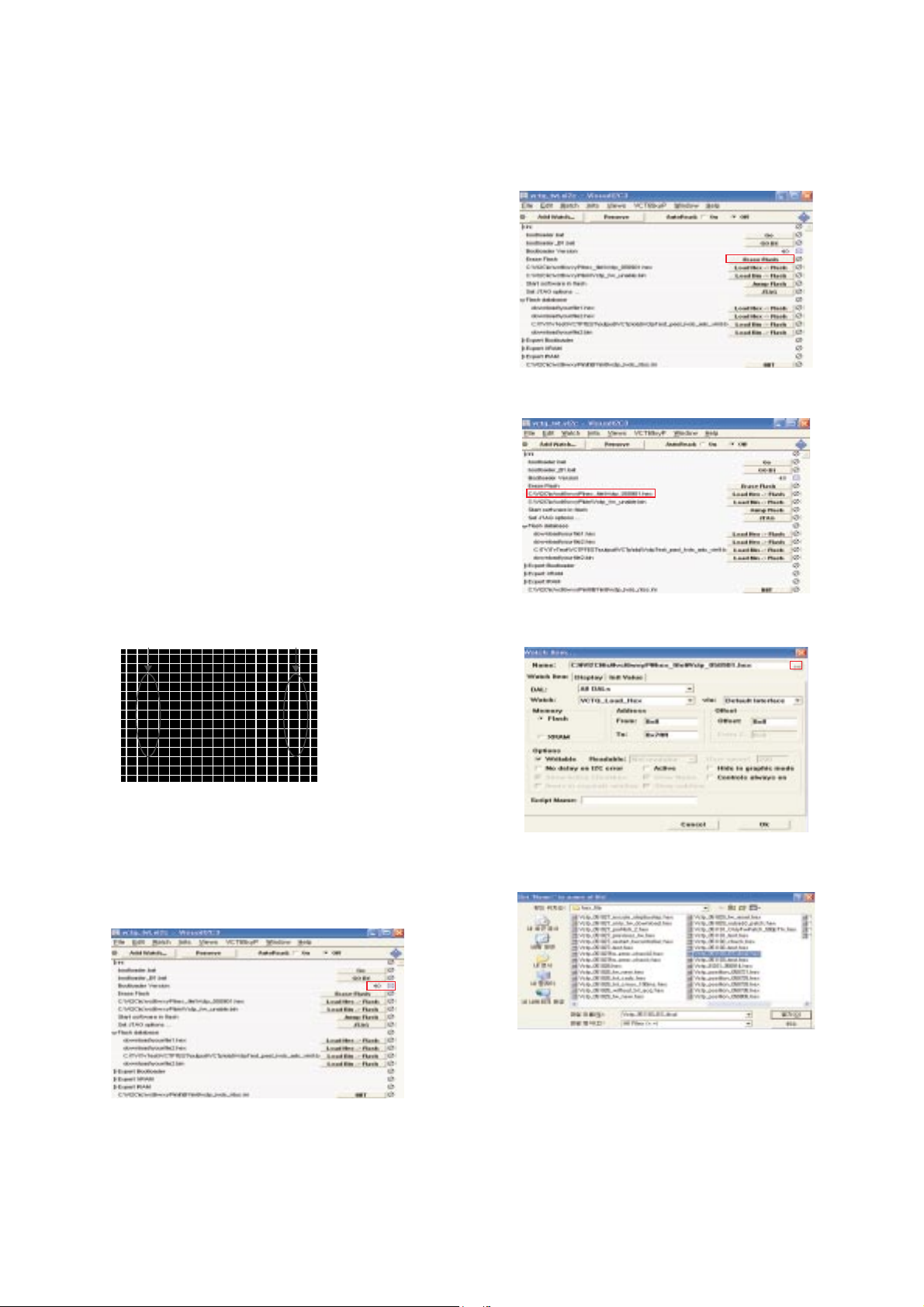
3. Soft ware download
1) Connect JIG to P004 of Digital Board.
2) Connect SCL line of JIG Switch to Ground.
3) Turn on JIG and supply 6V to Digital Board. Terminate the
SCL of clause 2) by using Switch.
4) After termination of SCL line, wait for 3 second.
5) Execute ‘vct69xyp_main_graphic.vi2c’ program.
6) Click the TVT button.
7) Double click right check box of ‘Boot loader Version‘ line, and
then check to change to 40 from 0.
8) After checking ‘40’, Click the ‘Erase Flash’ button.
9) Double click ‘Edit Window’.
10) Click the file select button of Name to select file.
11) Select necessary file.
ADJUSTMENT INSTRUCTIONS
A
B
Copyright©2008 LG Electronics.Inc. All right reserved.
Only for training and service purposes.
LGE Internal Use Only

12) Download the file with ‘OK’ button.
13) Check download process(about 30~40 sec.).
4. DVCO Adjustment
1) This adjustment applies to the frame assembly unit
adjustment.
2) This adjustment is to adjust the crystal oscillator frequency of
VCTP IC and is done after receiving the EU05CH(digital
pattern) signal.
3) If you press the ADJ button to enter the SCREEN mode,
DVCO adjustment is automatically done.
(T/X may not operate properly during DVC0 adjustment.)
5. Temporary screen voltage adjustment
1) This adjustment applies to the frame assembly unit
adjustment.
2) Enter Screen Mode with ADJ button. Turn the screen volume
to disappear horizontal line.
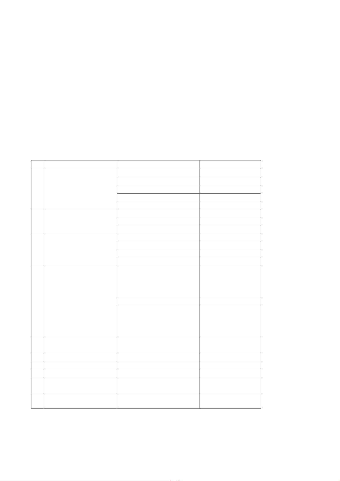
6. Focus Adjustment
6-1. Preliminary steps
Receive the PAL-B/G 07ch(Cross hatch pattern, <Fig 1>) and
Set the picture mode to “STANDARD”.
6-2. Adjustment
1) Adjust the lower Focus volume of FBT for the best focus of
vertical line A.
2) Adjust the upper Focus volume of FBT for the best focus of
area A.
3) Repeat above step 1) and 2) for the best overall focus.
7. Purity & Convergence adjustment
This adjustment should be operated when using the
CPT(without ITC) from CPT manufacturing place.
This adjustment must be done in the order of the following
flowchart.
7-1. Purity adjustment
(1) It makes CPT or CABINET enough to demagnetization.
(2) Receive the signal of red raster.
(3) Loosen fixed screw of DY and closely to CPT funnel part.
(4) Check the center of screen that PURITY MAGNET of CPT
by crossing adjustment. At this time, 4 & 6 pole magnet is
located to magnet of nothing.
(5) Move the DY to make equal red on whole screen and it does
not to make the DY by fixed screw after check a simple color
of Red/Green/Blue and white raster whether or not it is a
pollution of color.
(At this time, take care raster of screen and DY must fixing in
the condition which maintains a horizontality.)
(6) Check the TV set by move direction.
7-2. Convergence adjustment
These adjustments can the best condition of focus after finished
purity adjustment.
(1) Receive the signal of cross hatch that BACK RASTER is
black.
(2) Adjust brightness and luminosity till dot appear 9 ~12.
(3) Open angle of the two tab of 4 pole MAGNET by isogonic
angle and accord with vertical line of red and blue color in
the middle of screen.
(4) Maintain as angle of (3) and rotate the tab to accord with
vertical line of Red and Blue color in the middle of screen.
- 9 -
A
<Fig. 1>
Assembling DY to
CPT
CPT Assembling
As preparatory operations before
assembling CPT, wind cotton Tape for
protecting to CPT NECK and DY, CPT
connection parts. At this moment, end
of tape should be over-lapped and
wound in direct route to the NECK.
Let the screen Standard condition.
Operate Heat-Run at least 15
minutes.
Torque is to be 9-11 kg f.cm when
fixing DY.
Fix the Magnet to the position as
shown picture below. Be careful not to
make CPT neck shadow while
adjusting DY.
HEAT RUN
Degaussing
STC Pre-Adjustment
PURITY Adjustment
DY Fixing
SCREEN Voltage adj.
W/B Fixing
FOCUS not yet ADJ.
STC not yet ADJ.
DYC not yet ADJ.
Copyright©2008 LG Electronics.Inc. All right reserved.
Only for training and service purposes.
LGE Internal Use Only
Convergence Magnet
15 ~ 20mm
6Pole
4
2
 Loading...