

LG 29FS2RMB Schematic

COLOR TV
SERVICE MANUAL
CHASSIS : MC-035E
MODEL : 29FS2RMB/RNB
MODEL : 29FS2RMB/RNB-TP
website:http://biz.LGservice.com
e-mail:http://www.LGEservice.com/techsup.html
CAUTION
BEFORE SERVICING THE CHASSIS,
READ THE SAFETY PRECAUTIONS IN THIS MANUAL.

- 2 -
CONTENTS
CONTENTS .............................................................................................. 2
SAFETY PRECAUTIONS ..........................................................................3
CONTROL DESCRIPTIONS .................................................................... 4
SPECIFICATIONS .................................................................................... 7
ADJUSTMENT INSTRUCTIONS ............................................................. 8
TROUBLE SHOOTING .......................................................................... 15
PRINTED CIRCUIT BOARD ....................................................................20
BLOCK DIAGRAM ................................................................................. 27
EXPLODED VIEW .................................................................................. 30
EXPLODED VIEW PARTS LIST ..............................................................31
REPLACEMENT PARTS LIST ............................................................... 32
SVC. Sheet ..................................................................................................

- 3 -
SAFETY PRECAUTIONS
Many electrical and mechanical parts in this chassis have special safety-related characteristics. These parts are identified by in
the Schematic Diagram and Replacement Parts List.
It is essential that these special safety parts should be replaced with the same components as recommended in this manual to
prevent X-RADIATION, Shock, Fire, or other Hazards.
Do not modify the original design without permission of manufacturer.
General Guidance
An Isolation Transformer should always be used during
the servicing of a receiver whose chassis is not isolated from
the AC power line. Use a transformer of adequate power rating
as this protects the technician from accidents resulting in
personal injury from electrical shocks.
It will also protect the receiver and it's components from being
damaged by accidental shorts of the circuitry that may be
inadvertently introduced during the service operation.
If any fuse (or Fusible Resistor) in this TV receiver is blown,
replace it with the specified.
When replacing a high wattage resistor (Oxide Metal Film
Resistor, over 1W), keep the resistor 10mm away from PCB.
Keep wires away from high voltage or high temperature parts.
Due to high vacuum and large surface area of picture tube,
extreme care should be used in handling the Picture Tube.
Do not lift the Picture tube by it's Neck.
X-RAY Radiation
Warning:
To determine the presence of high voltage, use an accurate
high impedance HV meter.
Adjust brightness, color, contrast controls to minimum.
Measure the high voltage.
The meter reading should indicate
23.5 ± 1.5KV: 14-19 inch, 26 ± 1.5KV: 19-21 inch,
29.0 ± 1.5KV: 25-29 inch, 30.0 ± 1.5KV: 32 inch
If the meter indication is out of tolerance, immediate service
and correction is required to prevent the possibility of
premature component failure.
Before returning the receiver to the customer,
always perform an AC leakage current check on the
exposed metallic parts of the cabinet, such as antennas,
terminals, etc., to be sure the set is safe to operate without
damage of electrical shock.
Leakage Current Cold Check(Antenna Cold Check)
With the instrument AC plug removed from AC source,
connect an electrical jumper across the two AC plug prongs.
Place the AC switch in the on position, connect one lead of
ohm-meter to the AC plug prongs tied together and touch other
ohm-meter lead in turn to each exposed metallic parts such as
antenna terminals, phone jacks, etc.
If the exposed metallic part has a return path to the chassis, the
measured resistance should be between 1MΩ and 5.2MΩ.
When the exposed metal has no return path to the chassis the
reading must be infinite.
An other abnormality exists that must be corrected before the
receiver is returned to the customer.
Leakage Current Hot Check (See below Figure)
Plug the AC cord directly into the AC outlet.
Do not use a line Isolation Transformer during this check.
Connect 1.5K/10watt resistor in parallel with a 0.15uF capacitor
between a known good earth ground (Water Pipe, Conduit, etc.)
and the exposed metallic parts.
Measure the AC voltage across the resistor using AC
voltmeter with 1000 ohms/volt or more sensitivity.
Reverse plug the AC cord into the AC outlet and repeat AC
voltage measurements for each exposed metallic part. Any
voltage measured must not exceed 0.75 volt RMS which is
corresponds to 0.5mA.
In case any measurement is out of the limits specified, there is
possibility of shock hazard and the set must be checked and
repaired before it is returned to the customer.
Leakage Current Hot Check circuit
The source of X-RAY RADIATION in this TV receiver is the
High Voltage Section and the Picture Tube.
For continued X-RAY RADIATION protection, the
replacement tube must be the same type tube as specified in
the Replacement Parts List.
1.5 Kohm/10W
To Instrument's
exposed
METALLIC PARTS
Good Earth Ground
such as WATER PIPE,
CONDUIT etc.
AC Volt-meter
IMPORTANT SAFETY NOTICE
0.15uF
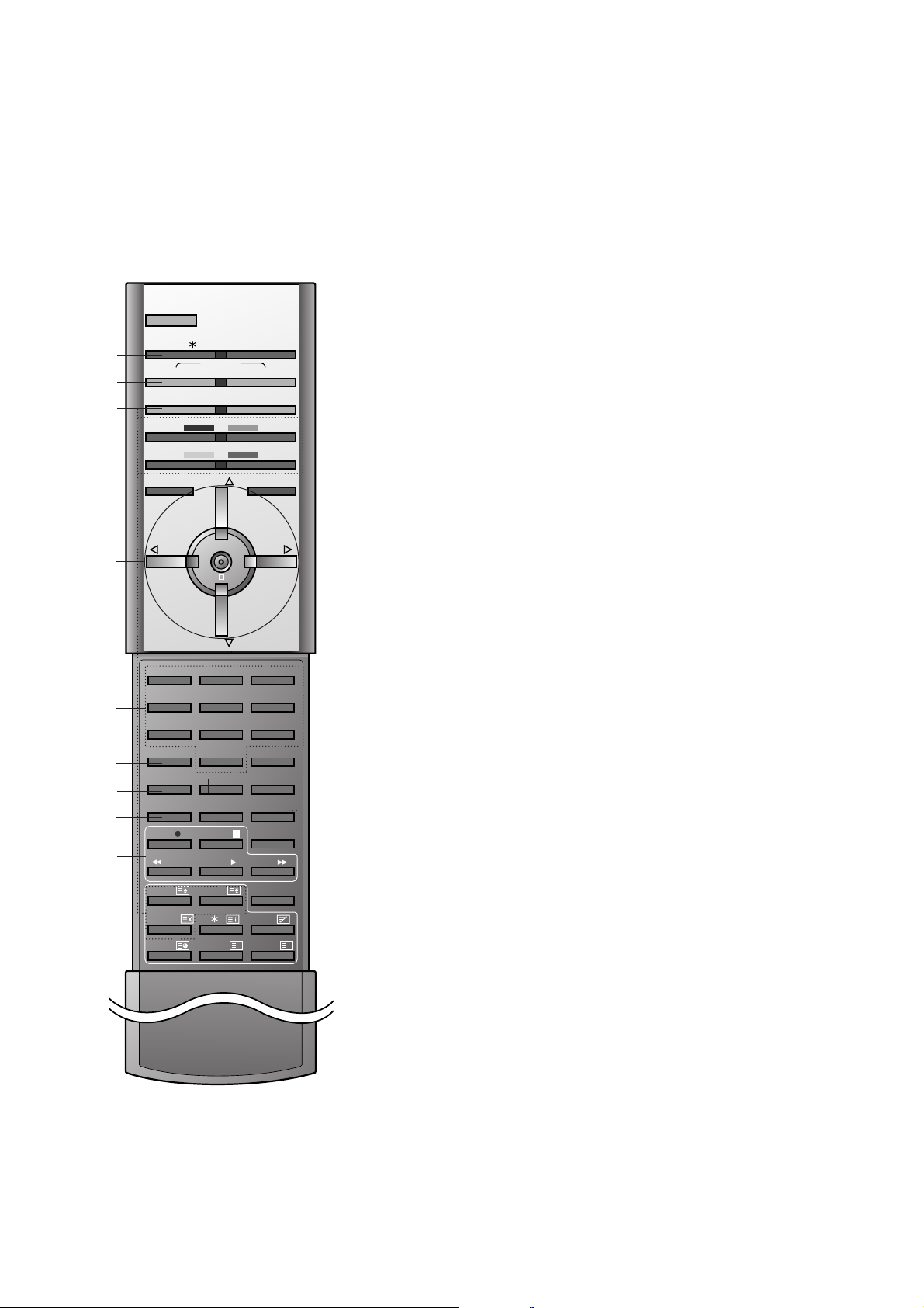
All the functions can be controlled with the remote control handset.
Some functions can also be adjusted with the buttons on the front
panel of the set.
Remote control handset
Before you use the remote control handset, please install the batteries. See the next page.
1. POWER
switches the set on from standby or off to standby.
2. EYE/
*
(option)
switches the eye function on or off.
3. TURBO SOUND BUTTON
selects Turbo sound.
4. PIP BUTTONS (option)
PIP
switches the sub picture on or off.
PR +/-
selects a programme for the sub picture.
SWAP
alternates between main and sub picture.
INPUT
selects the input mode for the sub picture.
SIZE
adjusts the sub picture size.
STILL
freezes motion of the sub picture.
POSITION
relocates the sub picture in clockwise direction.
5. MENU
selects a menu.
6.
DD / EE
(Programme Up/Down)
selects a programme or a menu item.
switches the set on from standby.
FF / GG
(Volume Up/Down)
adjusts the volume.
adjusts menu settings.
OK
accepts your selection or displays the current mode.
7. NUMBER BUTTONS
switches the set on from standby or directly select a number.
8. PSM (Picture Status Memory)
recalls your preferred picture setting.
9. SLEEP
sets the sleep timer.
10. I/II
selects the language during dual language broadcast.
selects the sound output (option).
11. MAIN STILL
freezes motion of the picture.
12. VCR BUTTONS
control a LG video cassette recorder.
123
456
7
PSM SSM
8
0
I/II
9
MAIN STILL
FAVOURITE
INDEX
POWER
EYE/ TV/AV
PIP TEXT
PR - PR +
INPUTSWAP
MENU PR
VOL
OK
VOL
PR
MUTE
PLAY
FF
ARC
REW
REC
LIST
Q.VIEW
SLEEP
POSITION
MIX
MODE
M
STILL
REVEAL
?
TIME
SIZE
STOP
SOUND PICTURE
TURBO
1
2
3
4
5
6
7
8
10
11
9
12
- 4 -
CONTROL DESCRIPTIONS
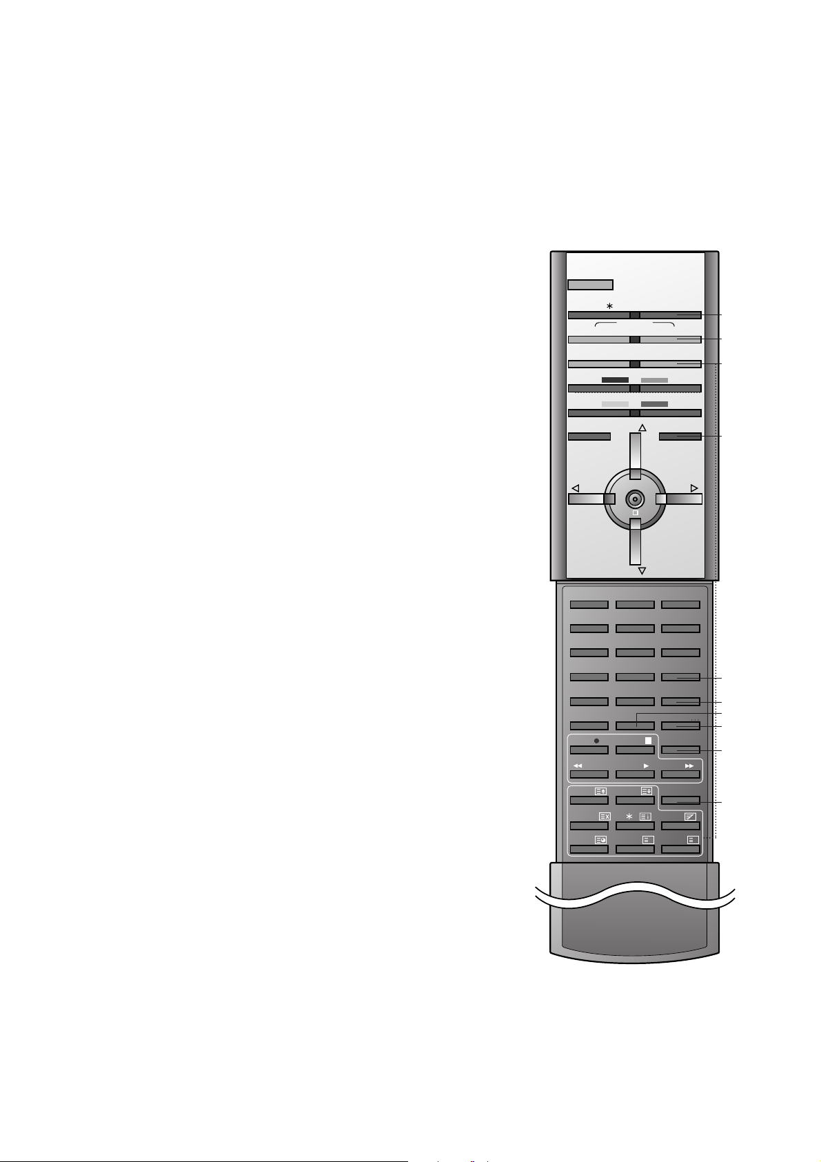
- 5 -
13. TV/AV
selects TV or AV mode.
switches the set on from standby.
14. TURBO PICTURE BUTTON
selects Turbo picture.
15. TELETEXT BUTTONS (option)
These buttons are used for teletext.
For further details, see the ‘Teletext’ section.
16. MUTE
switches the sound on or off.
17. SSM (Sound Status Memory)
recalls your preferred sound setting.
18. LIST
displays the programme table.
19. INDEX (option)
switches LED DISPLAY on or off.
20. FAVOURITE
selects a favourite programme.
21. Q.VIEW
returns to the previously viewed programme.
22. ARC (Aspect Ratio Control)
changes the picture format.
*
: No function
COLOURED BUTTONS : These buttons are used for teletext (only
TELETEXT models) or programme edit.
123
456
7
PSM SSM
8
0
I/II
9
MAIN STILL
FAVOURITE
INDEX
POWER
EYE/ TV/AV
PIP TEXT
PR - PR +
INPUTSWAP
MENU PR
VOL
OK
VOL
PR
MUTE
PLAY
FF
ARC
REW
REC
LIST
Q.VIEW
SLEEP
POSITION
MIX
MODE
M
STILL
REVEAL
?
TIME
SIZE
STOP
SOUND PICTURE
TURBO
13
14
15
16
17
18
20
19
21
22

- 6 -
1. MAIN POWER (ON/OFF)
switches the set on or off.
2. POWER/STANDBY INDICATOR
illuminates brightly when the set is in standby
mode.
dims when the set is switched on.
3. MENU
selects a menu.
4. OK
accepts your selection or displays the current
mode.
FF / GG
(Volume Down/Up)
adjusts the volume.
adjusts menu settings.
DD / EE
(Programme Up/Down)
selects a programme or a menu item.
switches the set on from standby.
5. REMOTE CONTROL SENSOR
6. AUDIO/VIDEO IN SOCKETS (AV3)
Connect the audio/video out sockets of external equipment to these sockets.
S-VIDEO/AUDIO IN SOCKETS (S-AV)
Connect the video out socket of an S-VIDEO
VCR to the S-VIDEO socket.
Connect the audio out sockets of the SVIDEO VCR to the audio sockets as in AV3.
7. EYE (option)
adjusts picture according to the surrounding
conditions.
8. HEADPHONE SOCKET
Connect the headphone plug to this socket.
9. PC INPUT SOCKET (option)
Connect the monitor output socket of the
PERSONAL COMPUTER to this socket.
Note : Set the resolution of PC to VGA
640x480 (60 Hz) video mode to use this set as
PC monitor.
Front panel
ON/OFF
1
Side panel
S-VIDEO
VIDEO
L/MONO RAUDIO
AV3
PC INPUT
8
6
9
2 75
3
4
- 7 -
SPECIFICATIONS
Note : Specification and others are subject to change without notice for improvement.
V Application Range
This specification can be applied to all the television related to
MC-035E Chassis.
V Specification
Each part is tested as below without special appointment.
1) Temperature : 25±5°C (77±9°F), CST : 40±5
2) Relative Humidity: 65±10%
3) Power Voltage: Standard Input voltage (100-240V~,
50/60Hz)
* Standard Voltage of each product is marked by models.
4) Specification and performance of each parts are followed
each drawing and specification by part number in
accordance with BOM.
5) The receiver must be operated for about 20 minutes prior to
the adjustment.
V Test Method
1) Performance : LGE TV test method followed.
2) Demanded other specification
EMC : EN55020, EN55013
SAFETY : IEC60065
V General Specification
V Feature and Function
No.
1
2
3
4
5
6
7
8
Item
Receiving System
AV Receiving System
Receiving Channel
Input Voltage
Screen Size
Tuning System
Operating Environment
Storage Environment
Specification
PAL/SECAM-B/G, D/K
PAL I, SECAM L/L’
NTSC M
NTSC M/PB,PAL BG,DK,I
SECAM BG, DK
1) VHF: E2~E12
UHF: E21~E69
CATV: S1~S20
HYPER: S21~S41
2) NTSC-M
VHF : 2~13CH
UHF : 14~69CH
CATV : 01~125CH
AC 110-240V/50Hz,60Hz
FLAT 29” , WIDE FLAT 32”/28”
FVS 100/200 program
1) Temp. : 0~40deg
2) Humidity : 0~85%
1) Tem : -20~60 deg
2) Humidity : 0~85%
No.
1
2
3
4
5
6
7
8
9
10
11
12
13
14
15
16
17
18
19
Item
Teletext
REMOCON
AV input
Component input
PERI TV connector
RGB input
2 Carrier Stereo
NICAM Stereo
2 Carrier Dual
NICAM Dual
SSC(Split Screen) Mode
Multi Picture Display Mode
Film Mode
Noise Reduction
Progressive Scan
Motion Detection
Swivel Speaker
Digital Eye
FM TRANSMITTER
Specification
TOP,FLOF
LG code
4(Side:1, Rear:3)
2(Rear:option)
Full SCART: 1(AV1:option)
Full SCART: 1(AV1:option)
BG,DK
BG,I
BG,DK
BG,I,
O
O
O
O
O
O
O(option-29FB90)
O
Option
- 8 -
1. Application scope
These instruction are applied to color television MC-035E
chassis.
2. Notes
1) Because this is not a hot chassis, it is not necessary to use
an isolation transformer However, the use of an isolation
transformer will help protect test instruments.
2) Adjustments must be done in the correct order
3) Surrounding adjustment condition : Adjustment is done in the
following condition unless specially designated.
Temperature : 25°C ± 5°C
Relative humidity : 65% ± 10%
4) The AC input voltage of the receiver must remain at rated
voltage 220V ± 10% while adjusting.
5) The receiver must be operated for about 15 minutes prior to
the adjustment.
3. DVCO Adjustment
1) This adjustment applies to the frame assembly unit
adjustment.
2) This adjustment is to adjust the crystal oscillator frequency of
VPC9407 and is done after receiving the digital pattern
signal.
3) If you press the IN-START key to enter the adjustment mode,
DVCO adjustment is automatically done.
(T/X may not operate properly during DVCO adjustment.)
4. Temporary screen voltage adjustment
1) This adjustment applies to the frame assembly unit
adjustment.
2) Press the ADJ key on the remote controller to make a
horizontal line. Turn the screen volume not to see one
horizontal line and turn oppositely until it starts to display.
5. HOLD down operation check
1) This check step is implemented during the frame assembly
process.
2) Check method : Short circuit the R1471, P418 of Main2 JP
display part and check if it switches to ST-BY.
(Install 30K resistances in parallel to the R1471 on jig.)
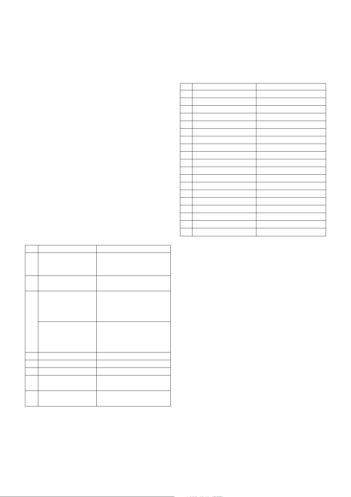
6. Focus Adjustment
6-1. Preliminary steps
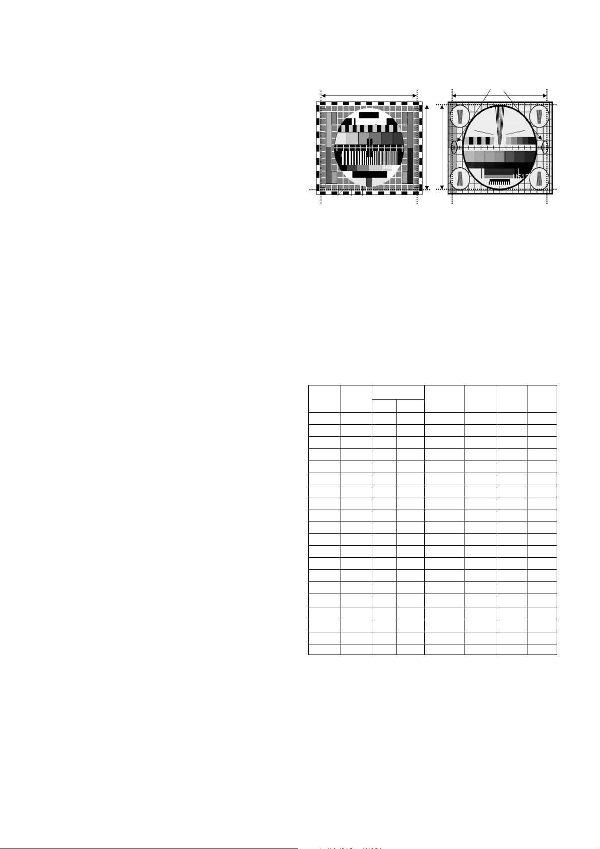
Receive the PAL-B/G 07ch(Cross hatch pattern, <Fig 6>) and
Set the picture mode to “STANDARD”.
6-2. Adjustment
1) Adjust the lower Focus volume of FBT for the best focus of
vertical line B.
2) Adjust the upper Focus volume of FBT for the best focus of
area A.
3) Repeat above step 1) and 2) for the best overall focus.
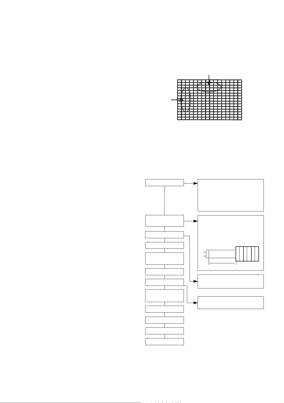
7. Purity & convergence Adjustment
Adjustment should be operated when using the CPT(without
ITC from CPT manufacturing place)
This adjustment must be done in the order of the following
flowchart.
ADJUSTMENT INSTRUCTIONS
Connect DY and
Magnet to CPT
Assemble CPT
As preparatory process before
assembling the CPT, wrap surface
protection tape on CPT neck, DY and
CPT connection parts. The tape should
be over-lapped at the end and must be
straight form against the neck.
Set the screen to STANDARD.
Heat fun for at least 15 minutes.
When fixing the DY, the torque
should be within 9 to 11 Kg f.cm.
Fix the Magnet in the location shown
in below figure. There should not be
any CPT neck shadow during
temporary DY adjustment.
HEAT RUN
Degaussing
Temporary STC
adjustment
Purity Adjustment
DY Fixing
Screen voltage
adjustment
W/B Fixing
FOCUS not yet ADJ.
STC not yet ADJ.
DYC not yet ADJ.
6pole 4 2
F
F
15 ~ 20mm
A
B
<Fig. 6>

7-1. Purity adjustment
1) Degauss the CPT and CABINET enough.
2) Receive red RASTER signal.(PG50ch)
3) Remove fixing screw of DY and stick DY to opening part(CPT
FUNNEL part)
4) Make crossing adjustment to the Magnet of CPT and make
the R-land is placed on center correctly. At this moment, 4
pole and 6 pole magnet should be at the position of no
magnetic field.
5) Move DY and make whole screen to be equal red, and fix the
DY with fixing SCREW after checking color pollution in each
single color and white RASTER of green/blue/red.(At this
time, be careful about inclination and DY should be fixed
keeping horizontality.)
6) Check the receiver in direction of East, West, South, North.
Adjust with supporting MAGNET when adjustment is not
operated.
7-2. Convergence adjustment
This adjustment should be operated at the best condition of
FOCUS after finishing the PURITY adjustment.
1) BACK RASTER receives black CROSS HATCH signal.
2) Adjust Brightness so that there are 9-12 dots.
3) Widen two tabs of 4pole Magnet with equal angles and
accord red, blue vertical lines at the center of screen.
4) With keeping angle of "3. clause", rotate tab and accord
red/blue, green vertical lines at the center of screen.
5) Widen two tabs of 6pole Magnet with equal angles and
accord red, blue vertical lines at the center of screen.
6) With keeping angle of "5. clause", repeat the adjustment from
"3. clause" to "5. clause" keeping in mind the movement of
red, blue, green when the horizontal lines are twisted.
7) Move DY up, down, left, right and make the convergence to
be optimal condition and stick rubber wedge to CPT so that
the DY not to move.
8. Screen voltage Adjustment
8-1. Preliminary steps
1) Turn the power supply of the TV set on.
2) The set must be operated for about 15 minutes prior to the
adjustment.
8-2. Adjustment
1) Adjust in the condition of no RF signal or after recieving the
PAL-B/G 05ch(Digital pattern)
2) Press ADJ key on the Remote controller to make horizontal
line.
Turn the Screen Volume not to see one horizontal line and
turn oppositely until it starts to display.
9. White balance Adjustment
This adjustment should be performed after screen voltage
adjustment.
For manual adjustment, refer to the following procedure
9-1. Test equipment
1) Automatic White Balance Meter(Low/High Light Pattern)
- Automatic adjustment
2) White Balance Meter(CRT Color Analyzer, CA-100) : 1 set
3) Remote controller for adjustment
9-2. Preliminary steps
1) Tune the TV set to receive an 100% white pattern.
2) This adjustment should be performed after screen voltage
adjustment.
9-3. Adjustment
1) White Balance should be adjusted with White balance meter
and the remote controller.
2) Press the IN-START key to enter the adjustment mode,
search for RGB W-B mode with CH
D, E, and select with
VOL key.
3) Select the ajustment item with CH
D, E key.
4) Adjust the data with Press VOL
F, G key.
5) Adjustment procedure
a. Adjust the "CONTRAST" and "BRIGHT" so the bright level
to be 3.5 Ft_L.
b. Adjust "Y" value of High Light with GD(G-Drive) and adjust
"X" value with BD(B-Drive) and make color coordinates of
High Light which is specified in "clause f".
c. Adjust the "CONTRAST" and "BRIGHT" so the bright level
to be 4.5 Ft_L.
d. Adjust "Y" value of Low Light with GC(G-Cutoff) and
adjust "X" value with BC(B-Cutoff) and make color
coordinates of Low Light which is specified in "clause f".
e. Repeat a~d until the High/ Low color coordinates satisfies
the table of “claud f”
f. Check the adjusted color coordinates with white balance
meter.
- 9 -
Color Temperature.
13000K
X coordinate
266 ± 8
Y coordinate
273 ± 8
RGB
W-B
MENU
RD(0~3F)
GD(0~3F)
BD(0~3F)
RC(0~3F)
GC(0~3F)
BC(0~3F)
29”
29
28
2C
1F
22
B0
Remark
For High Light adjustment
For Low Light adjustment

10. Deflection Data Adjustment
- Manual adjustment can be done by the following procdure.
10-1. Preliminary steps
1) Set the Deflection data with the remote controller.
2) Enter the Adjustment mode by pressing the INSTART button.
3) Select the “DEFLECT” to adjutst Deflection Data.
4) Press the CH D, E button to select adjustment items.
5) Press the VOL F, G button to adjust the data.
6) The TV set receives PAL-B/G Digital pattern(EU05ch).
NOTE : Initial adjustment is done based on PAL 100Hz.
If production line doesn’t the production line of LG
TV,receive available deflection adjustment pattern.
10-2. Adjustment
VL (Vertical Linearity)
Adjust the top & bottom size of inner circle to be equal.
Adjust Linearity of the upper/ lower part at the U-VL or L-VL.
VA (Vertical Amplitude)
Adjust upper and lower part of circle from the effective screen of
the CPT.to be distance of 6~7mm.
SC (Vertical S Correction)
Adjust the lattice width of the Top/Center/Bottom to be the
same.
As being decided by DY value of the using CPT, set as default
of the using CPT.
VS (Vertical Shift)
Adjust so that the horizontal center line of a digital circle pattern
is in accord with geometric horizontal center of the CPT.
HS (Horizontal Shift)
Adjust so that the vertical center line of a digital circle pattern is in
accord with geometric vertical center of the CPT.
EW (East-West Horizontal Width)
Adjust outer line of the left/ right outer lattice to be united with
effective boundary surface of CPT.
* Receive Cross-hatch pattern to adjust horizontal Pin-Cushion.
A-BOW(AFC Bow)
In line adjustment, not to change default value is basic.
A-ANG(AFC Angle)
In angle adjustment, adjust until inclination of left and right screen
should be precise.
EPP(East-West Pin Phase)
Adjust so that horizontal width of the uppermost part and horizontal
width of the lowermost part of received screen are to be the same.
EP (East-West Parabola)
Adjust so that middle portion of the outermost left and right vertical
line looks like parallel with vertical lines of the CPT.
UC(Upper Corner Correction)
Adjust so that corner vertical line of upper-left and upper-right to be
straight line after finishing EP adjustment.
LC(Lower Corner Correction)
Adjust so that corner vertical line of lower-left and lower-right to be
straight line after finishing EP adjustment.
V-SCR(V-Scroll)
Only adjust when V SHIFT is impossible.
* After adjusting as above, finish the Pin Cushion by re-
adjustment of EW, EPP, A-ANG, A-BOW, UC, LC.
* After adusting, move to “Store This Mode”. And then change to
“Store All Mode” and save by using press “OK” key.
10-3. Deflection setting data adjustment
* If the inclination adjustment is not correct when checking
PAL50P, NTSC60Hz, 576P, 480P, 1080i Mode after finishing
adjustment in PAL100Hz, adjust at each Mode again.
* PAL100Hz(RF) -> PAL 50P -> NTSC 60Hz(RF) -> 576P
(COMPONENT) -> 480P(COMPONENT) -> 1080i(COMPNONT)
- 11 -
A
Actual screen size
50Hz 60Hz
<Fig. 7>
Menu
VS
VA
HS
EW
EP
EPP
A-ANG
A-BOW
UC
LC
U-VL
L-VL
VL
SC
V-SCR
HPaDc
HPaAm
HPaPh
MpaAm
MPaDc
0 ~ 3F
0 ~ 3F
0 ~ 3F
0 ~ 3F
0 ~ 3F
0 ~ 3F
0 ~ 3F
0 ~ 3F
0 ~ 3F
0 ~ 3F
0 ~ 0F
0 ~ 0F
0 ~ 0F
0 ~ 0F
0 ~ 3F
0 ~ 3F
0 ~ 3F
0 ~ 3F
0 ~ 0F
0 ~ 0F
2A
35
26
15
31
2F
1D
1A
1D
1F
0B
05
07
02
1E
28
29
20
09
07
G -1
G -1
G -1
G +1
G -9
G -10
G -11
G +2
G -10
G -10
G -20
G +2
G +2
G -14
G -5
G -9
G -13
G +1
G -6
G -17
G -22
G -2
G -6
G +3
G -23
Range
RF PAL
100
RF NTSC 576P 480P 1080i
50P
- 12 -
11. TELETEXT position adjustment
After finishing deflection adjustment, execute this adjustment.
11-1. Vertical position adjustment of TEXT
(1) Sequence of Adjustment
1) Before entering the adjustment Mode, LEVEL 2.5 TEXT
receives possible channel.
2) Select ‘SOUNdetc PAGE’ with ‘INSTART’ key on remote
controller.
3) Using the CH +/- key, select the TXTV item to receive the
TEXT adn then press the 1,8,9 number key by turns.
4) After checking the LEVEL 2.5 TEXT 889PAGE to receive.
(2) Adjustment specification
In 189PAGE of LEVEL 2.5 TEXT, adjust to be same spaces
of the up/ down.
11-2. Horizontal position adjustment of TEXT
(1) Sequence of Adjustment
1) After adjusting kthe vertical position, press the 1, 5, 3
number key by turns to check received 153PAGE.
2) Using the CH +/- key, adjust the left/ right spaces to be
same.
(2) Adjustment specification
In 153PAGE of LEVEL 2.5 TEXT, adjust to be same spaces
of the left/ right.
11-3. Horizontal position adjustment of
Half TEXT
(1) Sequence of Adjustment
1) After selecting H.T.H(HALF TEXT H POSITION) item by
pressing the CH(-) key, adjust the left starting point of the
TEXT to be united with CPT center by pressing the VOL.
key.
2) At this time, take care of right TEXT not to get out of the
screen.
3) If the above adjustment is completed, press the ENTER
key to save the adjustment data.
(2) Adjustment specification
In LEVEL 2.5 TEXT, adjust the left starting point to be united
with CPT center.
12. Test method of transmission/
reception condition(wireless
sound model)
- Wireless Sound's efficiency inspections is executed to a
finished in a final inspection phase.
- Wireless Sound is a function which receives voice-singal by an
exclusive remote control and earphone, transmitts a FM
through transmitter to TV sound(MONITOR OUTPUT)
- If the received frequency which set up in OSD is being tunned
without using an exclusive remote control ,it is available to
receive in a general FM receiver.
1) Execute in Ch5, 25 or channel that output the voice signal.
2) Select a transmitted frequency in MENU OSD.
MENU -> SOUND -> X-WAVE -> Select frequency
3) A received frequency in an exclusive remote control or
received FM Radio is tuned to it which is same as frequency
in OSD.
4) Check out whether a signal generating to MAIN SPEAKER
generates in earphone or receiver or not.
5) There is no alternation and setting of adjusted DATA in the
process of inspecting FM TX.
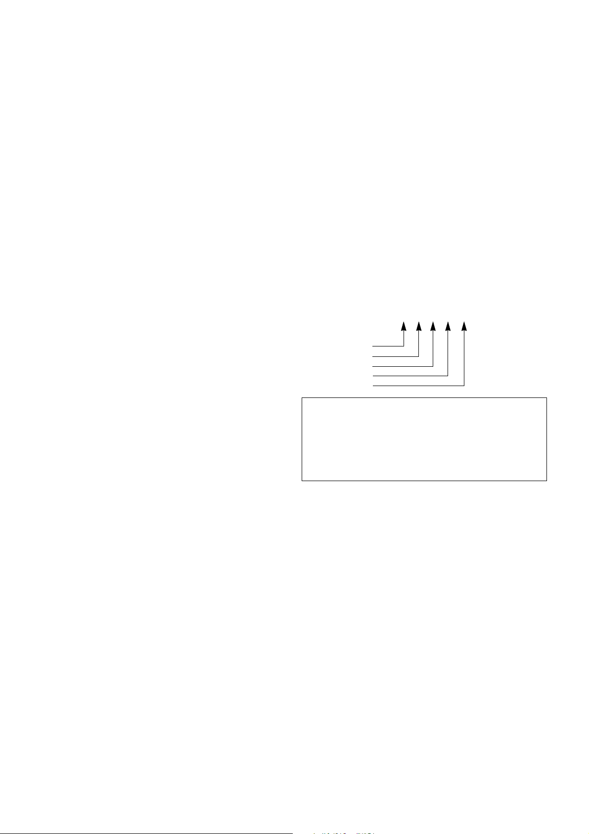
13.
OPTION adjustment
13-1. Preparation for Adjustment
1) This option adjustment decides function in accordance with
model.
Press the SVC TX adjustment Key(IN-START) or MENU
key, COLOR key at SVC mode, then adjust the option at
OPTION 1, 2, 3, 4, 5 mode.
2) Mark the option adjustment data like [111,11,111,11] in BOM.
13-2. Adjustment
1) Input OPTION value at by using number key on remote
controller at each OPTION adjustment mode.
2) Select ajustment item with CH
D,E key at each OPTION
mode.
3) Select specification of model with VOL
F,G key.
OP [113,63,112,201,248]
OPTION 1
OPTION 2
OPTION 3
OPTION 4
OPTION 5
* Mark of BOM
LEVEL PART NO. SPECIFICATION DESCRIPTION
1. 3141VMN382A MAIN CHASSIS ASSY OP[111,245,205,511,240]
In this model, the OPTION1 data is 111, OPTION2 data is 245,
the OPTION3 data is 205,the OPTION 4 data is 511, OPTION 5
data is 240.
- 13 -
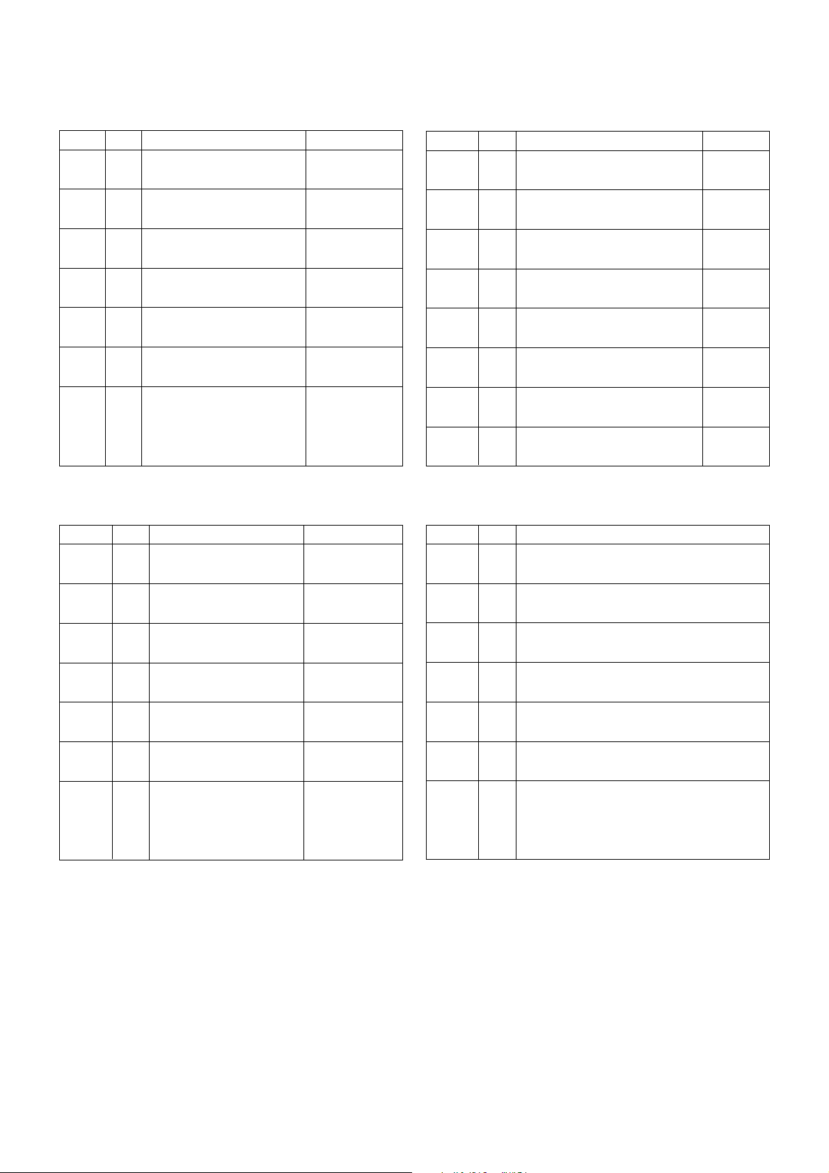
Table 3. OPTION 3
default
not used
WIDE
TEXT
CH+AU
HDEV
DOLBY
DGIDX
XD
Option Code
0
1
0
1
0
1
0
1
0
1
0
1
0
1
2
3
Function Remark
4:3 TV
16:9 TV
WITHOUT TEXT
WITH TEXT
Without D/K China or BB System
With D/K China or BBSystem
Not appu to Sound High deviation
Provide for Sound High deviation
Without Dolby
With Dolby
Without Digital Index
Wiht Digital Index
DRP DEMO
Fi-NE SYSTEM
XD
RESERVED
DCION
MALAY
RESER
EZAV
BOOST
Australia
FM TX
Option Code
0
1
0
1
0
1
0
1
0
1
0
1
0
1
2
3
Function
DYNAMIC CONTRAST OFF
DYNAMIC CONTRAST ON
NOT MALAYSIA
MALAYSIA
RESERVED
RESERVED
WITHOUT EZ-AV
WITH EZ-AV
BOOST OFF
BOOST ON
NOT AUSTRALIA
AUSTRALIA ONLY
Without FM TX
LOW BAND
HIGH BAND
RESERVED
Table 5. OPTION 5
TTable 2. OPTION 2
Australia
EU model
Non-EU model
ACMS
VOL
HPHON
DVD
VGA
AV SV
AV
Option Code
0
1
0
1
0
1
0
1
0
1
0
1
0
1
2
3
Function Remark
Without ACMS function
With ACMS function
NORMAL VOLUME CURVE
RUSHED VOLUME CURVE
Without HEADPHONE
With HEADPHONE
Without DVD INPUT
With DVD INPUT
Without VGA
With VGA
AV Status not save
AV Status save
3SCART
1SC + 2PH
PHONE ONLY
RESERVED
CHINA
EU model
EU model
Non EU model
Without TOP TEXT
NOT USED
NOT USED
EU model
Non EU model
200 PR
TSEAR
I/II SV
TOP
EYE
A2 ST
SYS
Option Code
0
1
0
1
0
1
0
1
0
1
0
1
0
1
2
3
Function Remark
100 PROGRAM SAVE
200 PROGRAM SAVE
Without Turbo Search function
With Turbo Search function
NO SAVE DUAL/SOUND Condition
SAVE DUAL SOUND Condition
FLOP TEXT
TOP TEXT
Without EYE MODULE
With EYE MODULE
NICAM
NICAM&FM STEREO/DUAL
BG/ID/K
B/G/L
BG/I/D/K/L
BG/I/D/K/M
Table 1. OPTION 1
 Loading...