How it Works
Log In / Sign Up
Buy Points
How it Works
FAQ
Contact Us
Questions and Suggestions
Users
LG
Loading...
#
27MA73D
27MA73D-PU
27MA73D-PZ
5
27MA73V-PZ
27MB35PH-B
2
27MB65PY
27MB65PY-B
27MB67PY-B
3
27MB85R
27MB85R-B
13
27MB85Z
27MB85Z-B
12
27MC37HQ
27MD53D
27MD53D-PZ
8
27MD5KA
2
27MD5KA-B
15
27MD5KB
27MD5KL
27MD5KL-B
24
27MD5KL-B.AEK
27MD5KLB-B
27MK4
27MK400H
27MK400H-B
8
27MK430H
2
27MK430H-B
9
27MK430H-B.AEK
27MK43T-B
27MK4 series
27MK600M
2
27MK600M-B
6
27MK600M-W
27MK60TM
2
27ML600M
27ML600M-B
27ML600S
27ML600S-W
7
27MN43D
27MN43T
27MN60HM-WJ
27MN60T
27MP33HQ-B
27MP35HQ
27MP35HQ-B
5
27MP35VQ
2
27MP35VQ-B
4
27MP35VQ-W
27MP36HQ
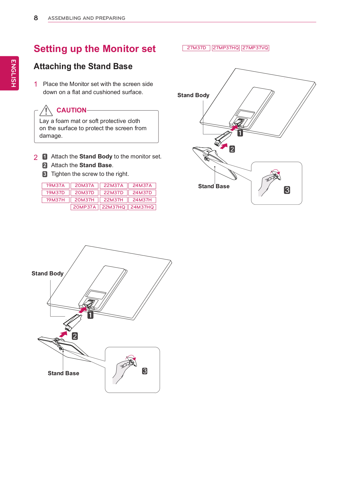
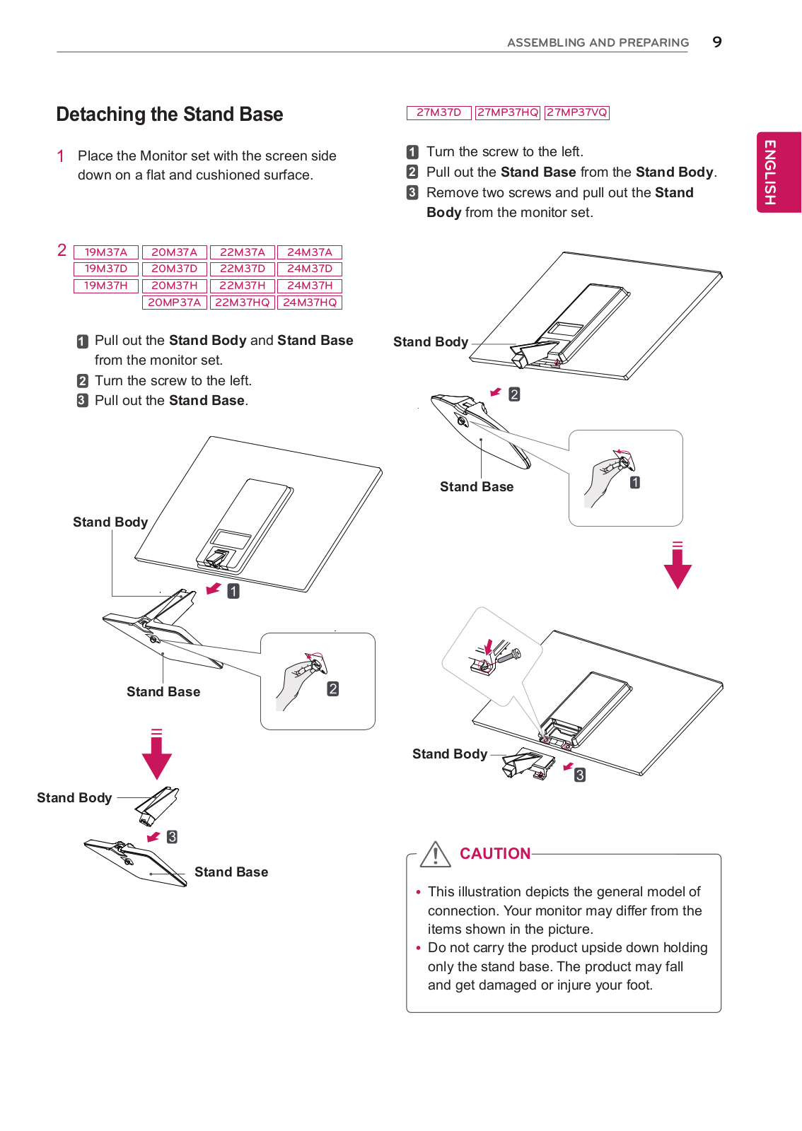
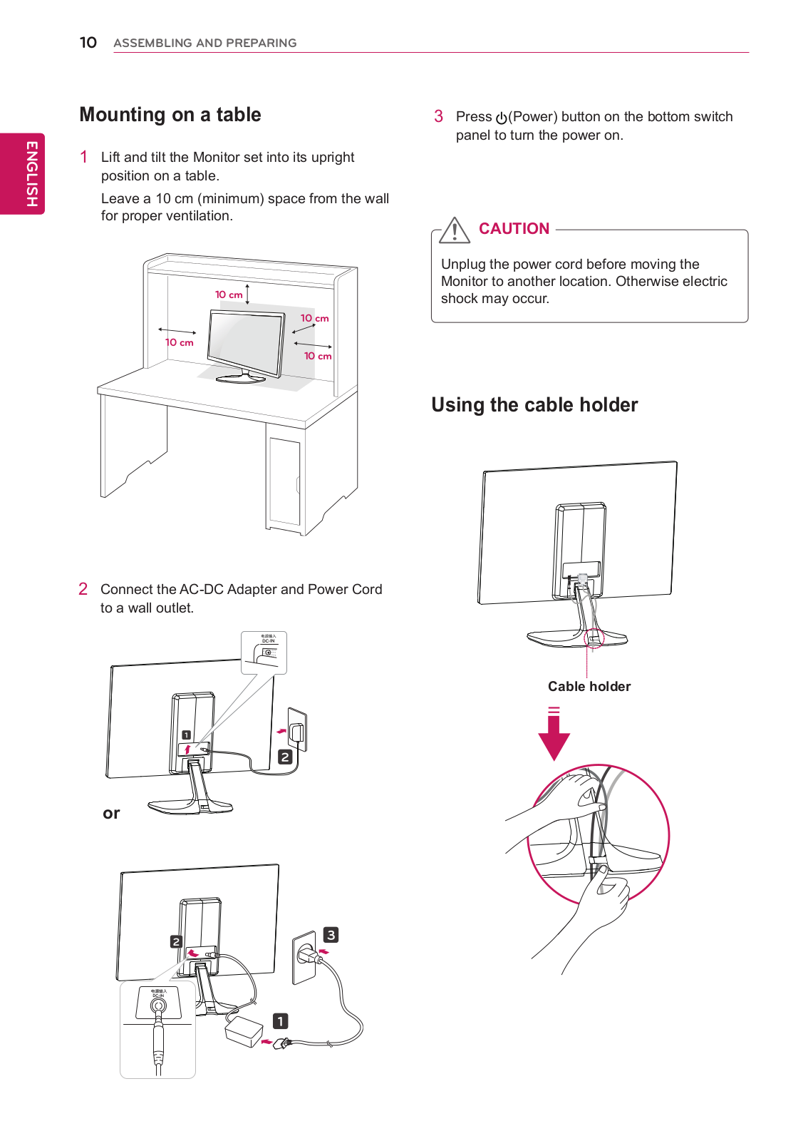
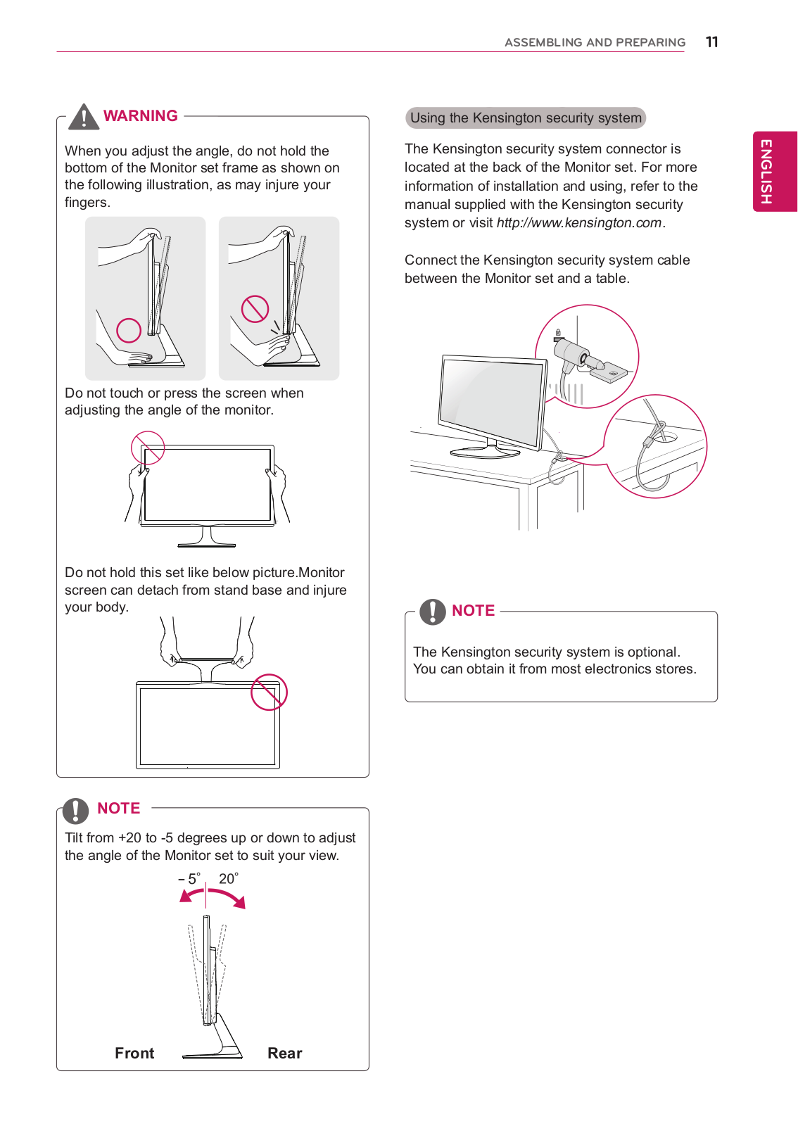
27MP37HQ
27MP37HQ-B
27MP37VQ
27MP37VQ-B
2
27MP38HQ
2
27MP38VQ
2
27MP38VQ-B
9
27MP47HQ
2
27MP48HQ
2
27MP48HQ-P
2
27MP500-B
15
27MP55HQ
2
27MP55HQ-P
27MP57HQ
27MP57HT
27MP57HT-P
27MP57VQ
27MP58HQ
2
27MP58VQ
2
27MP58VQ-P
7
27MP58VQ-W
27MP59G
2
27MP59G-P
3
27MP59HT
27MP59HT-P
2
27MP60G-B
2
27MP65HN-P
27MP65HQ
27MP65HQ-P
27MP65VQ
27MP66HQ-C
27MP67HQ
3
27MP67VQ
2
27MP68HM-P
2
27MP68VQ
2
27MP68VQ-P
2
27MP75HM
2
27MP75HM-P
3
27MP77HM
2
27MP77HM-P
2
27MP77SM
2
27MP89HM
2
27MP89HM-S
14
27MS53S
2
27MS53S-PZ
5
27MS53V
27MS53V-PZ
27MS73D-PH
3
27MS73S
3
27MS73S-PR
27MS73S-PZ
15
Loading...
Loading...
Nothing found
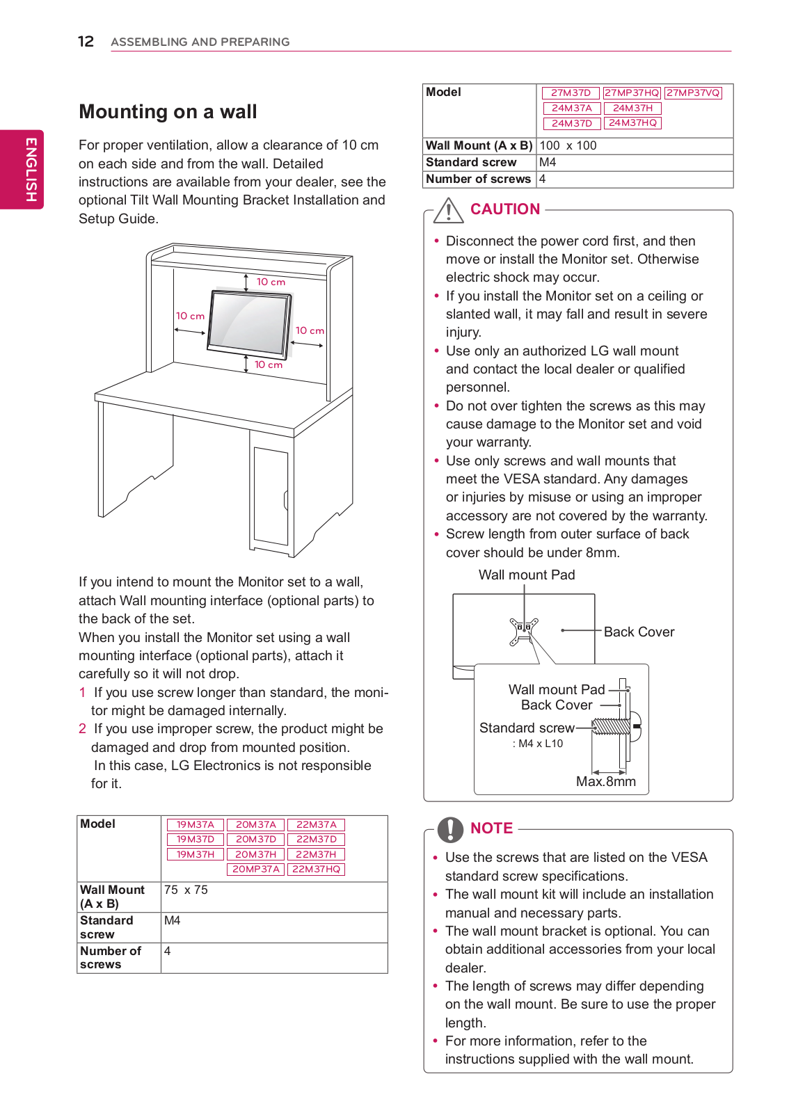
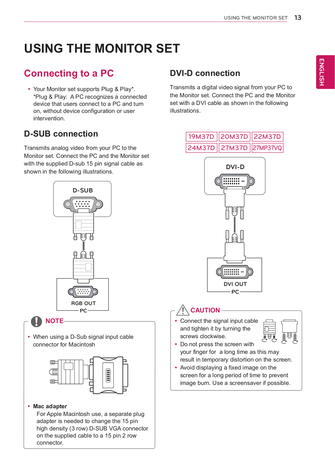
27MP37HQ-B
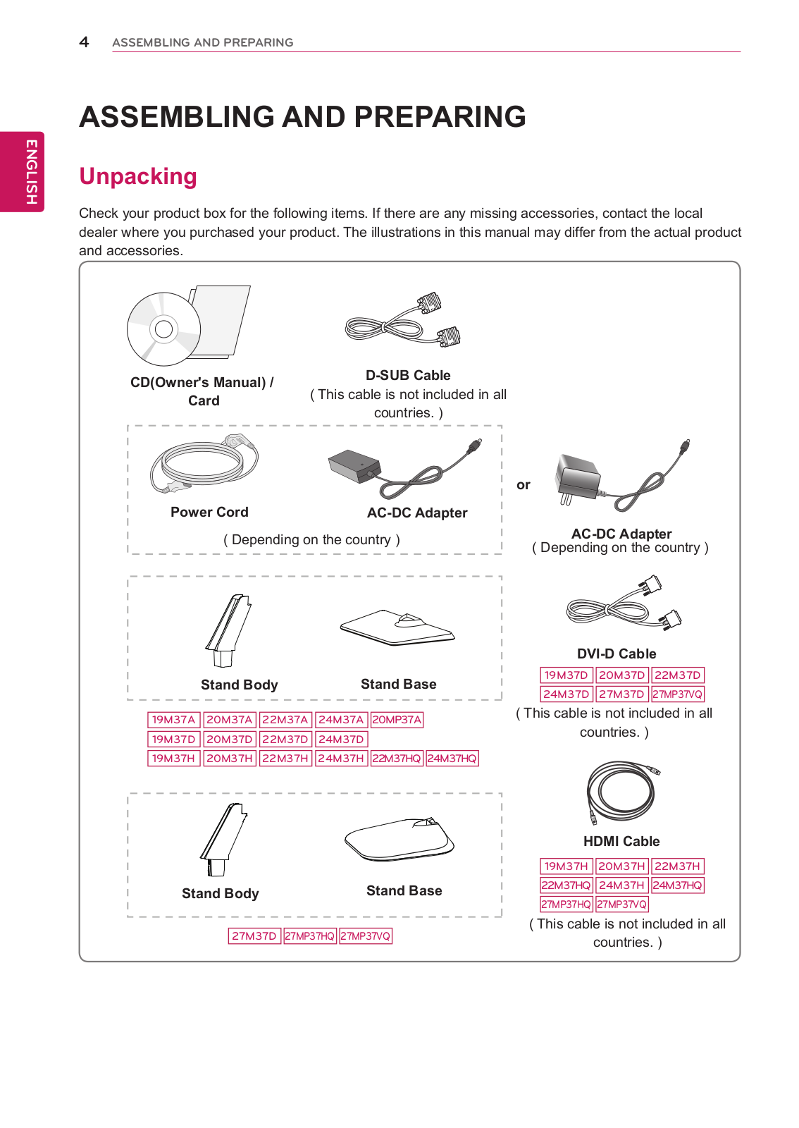
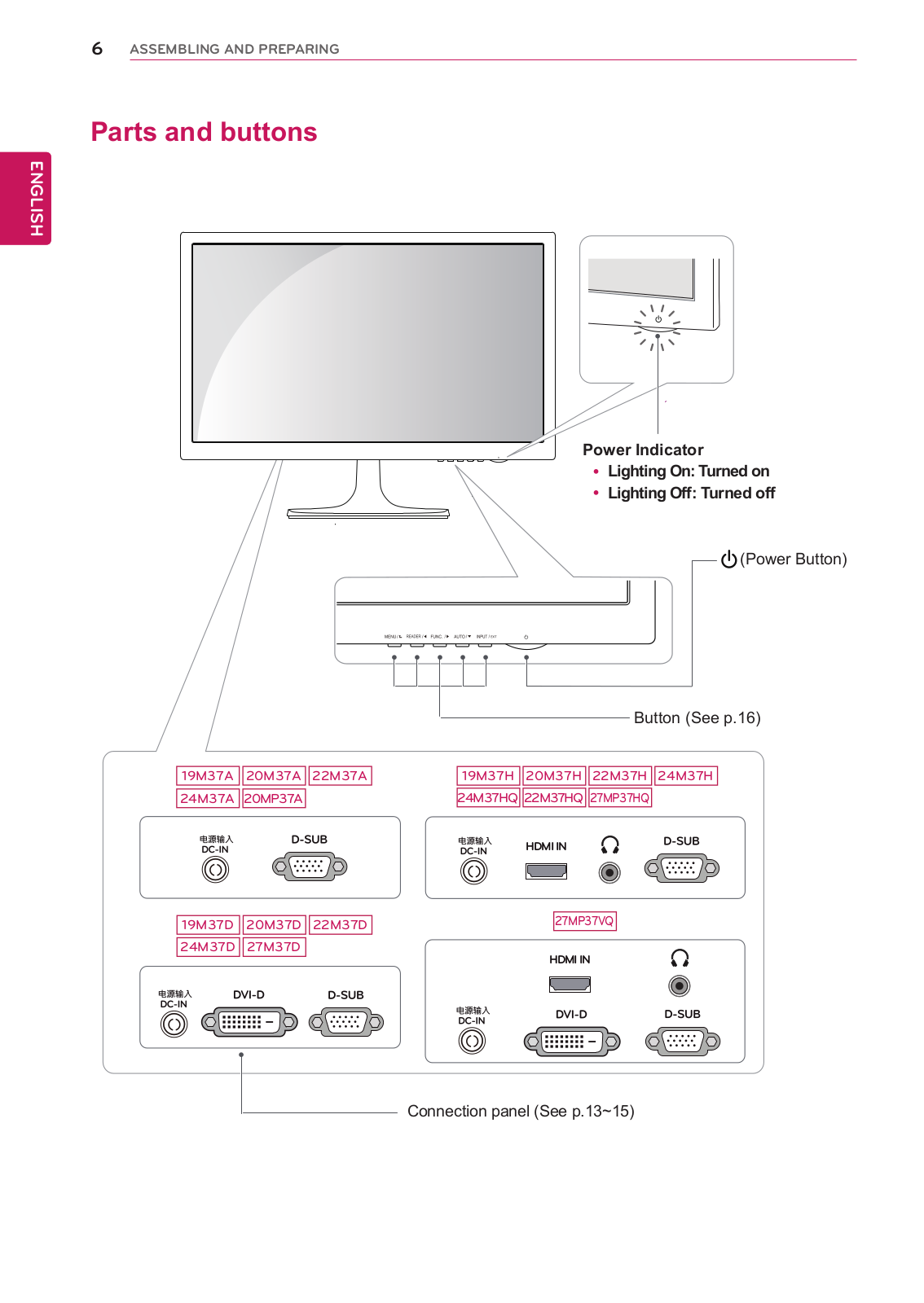
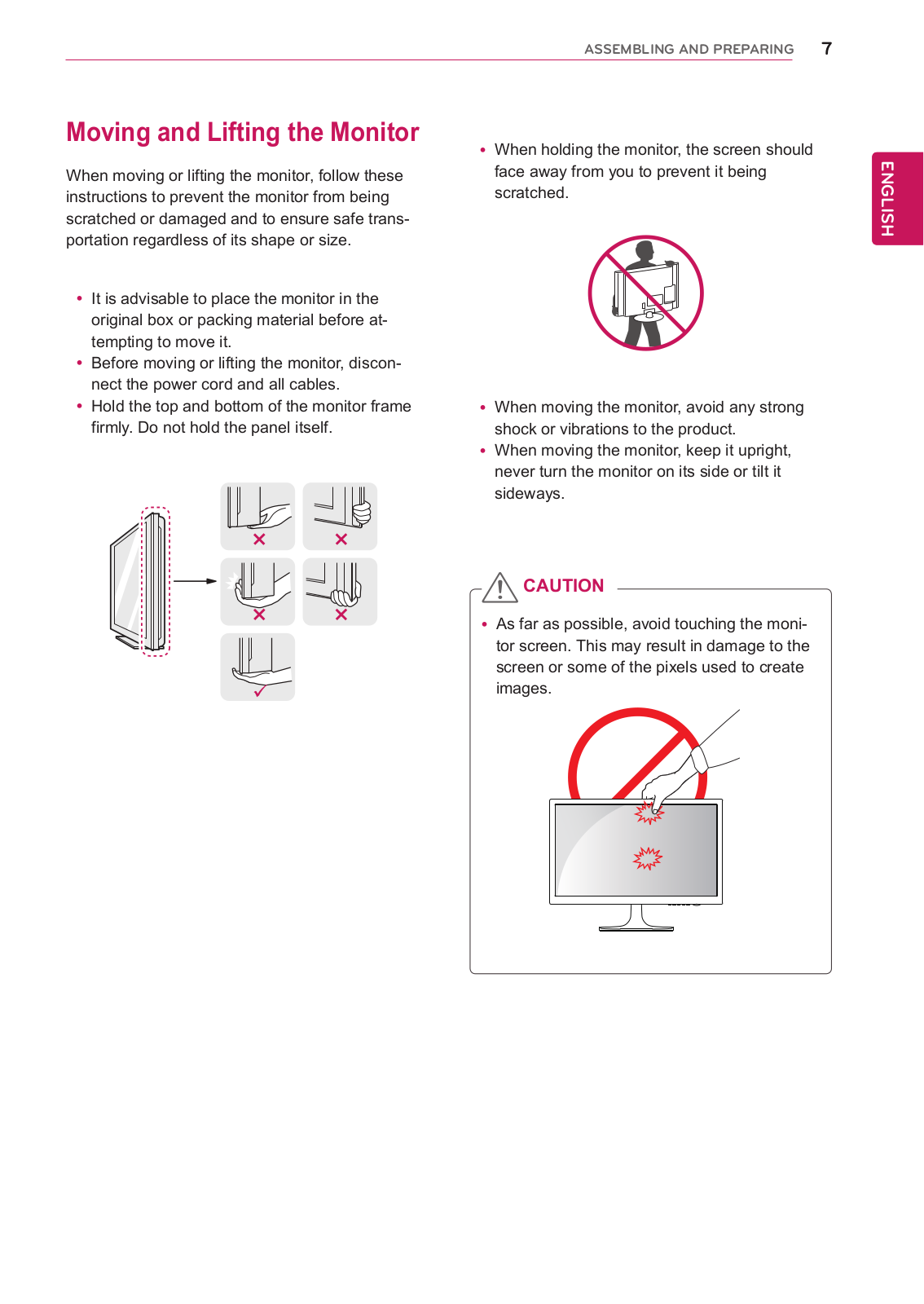
User manual
43 pgs
14.19 Mb
0
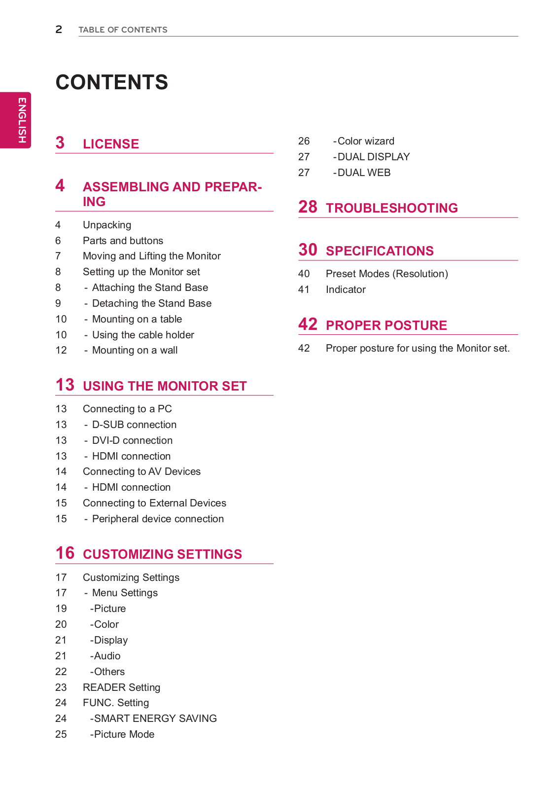
Table of contents
Loading...
LG 19M37A-B, 27MP37HQ-B User manual
...
LG User manual
Download
Specifications and Main Features
Frequently Asked Questions
User Manual
Download
Loading...
+
30
hidden pages
Unhide
You need points to download manuals.
1 point = 1 manual.
You can buy points or you can get point for every manual you upload.
Buy points
Upload your manuals
 Loading...