How it Works
Log In / Sign Up
Buy Points
How it Works
FAQ
Contact Us
Questions and Suggestions
Users
LG
Loading...
#
27EN43VQ
2
27EN43VQ-B
27GK750F
2
27GK750F-B
9
27GL63T
27GL63T-B
20
27GL63T-B.AEK
27GL650F
2
27GL650F-B
26
27GL830-B
2
27GL83A
2
27GL83A-B
19
27GL850
27GL850-B
27
27GL850-B.AEU
27GN600-B
17
27GN650-B
16
27GN750
2
27GN750-B
27
27GN800-B
23
27GN850-B
13
27GN880-B
19
27GN88A-B
12
27GN950
27GN950-B
24
27GN95B
27GP83B-B
27GP850-B
27GP950-B
2
27HIZ10
27HJ710S
27HJ710S-W
10
27HJ712C
27HJ712C-W
22
27HJ713C-B
7
27HK510S-W
12
27LC2R
41
27LC2R Series
2
27LC2R-ZJ
2
27LS5400
4
27LS540T
27LU55
27LZ50C
27LZ5RV
12
27LZ5RV-ZC
27M37D
27M45H
27M45H-B
2
27M45HQ
2
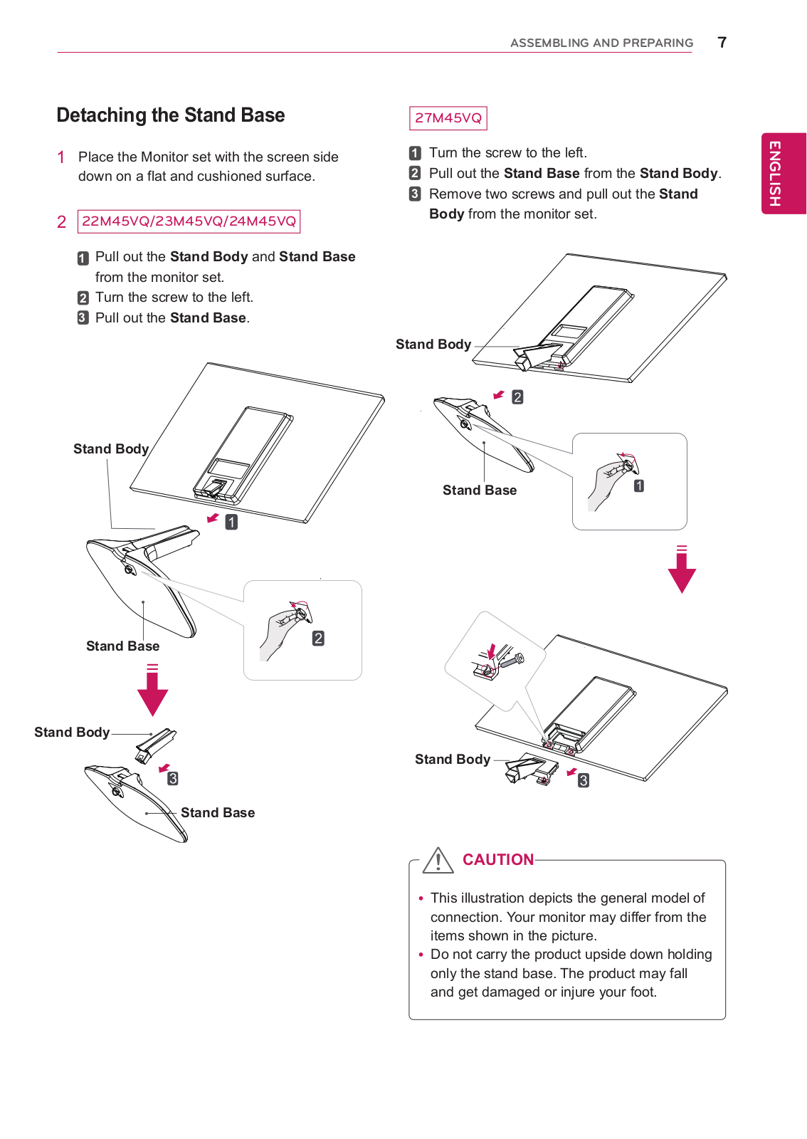
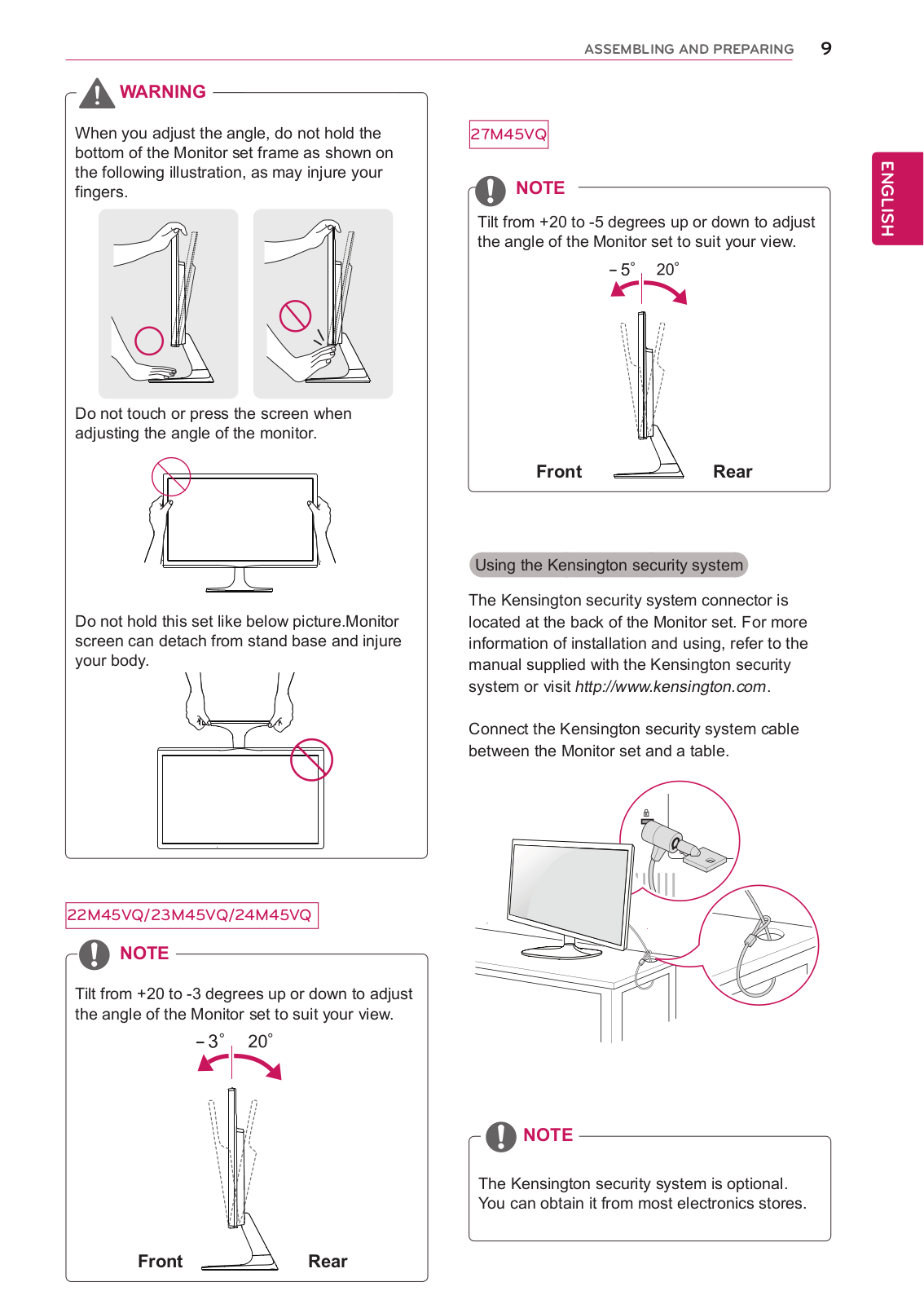
27M45VQ
27M45VQ-B
27M47H
27M47HQ
27M47VQ
27M47VQ-B
27MA43D
5
27MA43D-PR
2
27MA43D-PZ
15
27MA43T
27MA53D
3
27MA53D-PR
27MA53D-PZ
8
27MA53S
2
27MA53V
2
27MA73D
27MA73D-PU
27MA73D-PZ
5
27MA73V-PZ
27MB35PH-B
2
27MB65PY
27MB65PY-B
27MB67PY-B
3
27MB85R
27MB85R-B
13
27MB85Z
27MB85Z-B
12
27MC37HQ
27MD53D
27MD53D-PZ
8
27MD5KA
2
27MD5KA-B
15
27MD5KB
27MD5KL
27MD5KL-B
24
27MD5KL-B.AEK
27MD5KLB-B
27MK4
27MK400H
27MK400H-B
8
27MK430H
2
27MK430H-B
9
27MK430H-B.AEK
27MK43T-B
27MK4 series
27MK600M
2
27MK600M-B
6
27MK600M-W
27MK60TM
2
27ML600M
27ML600M-B
Loading...
Loading...
Nothing found
27M45VQ-B
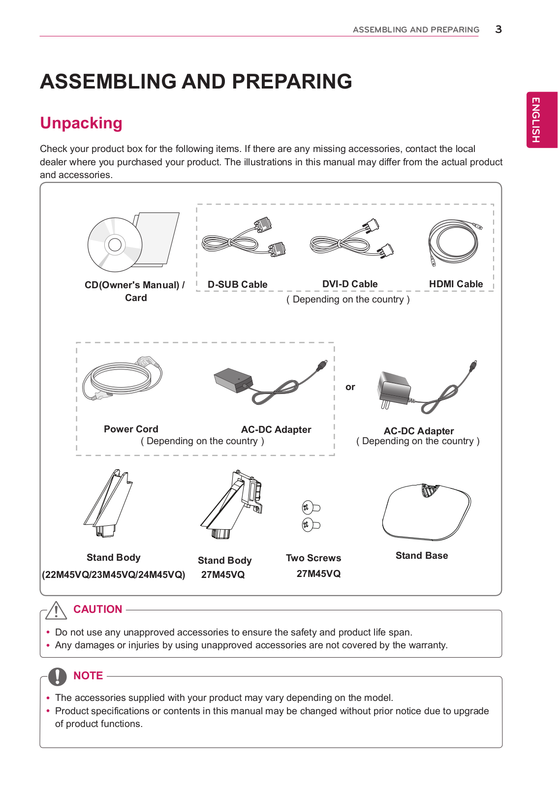
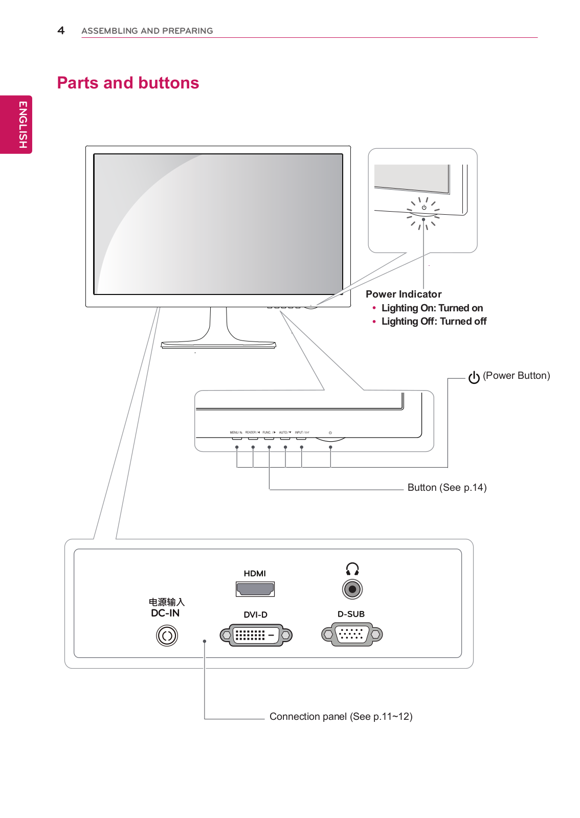
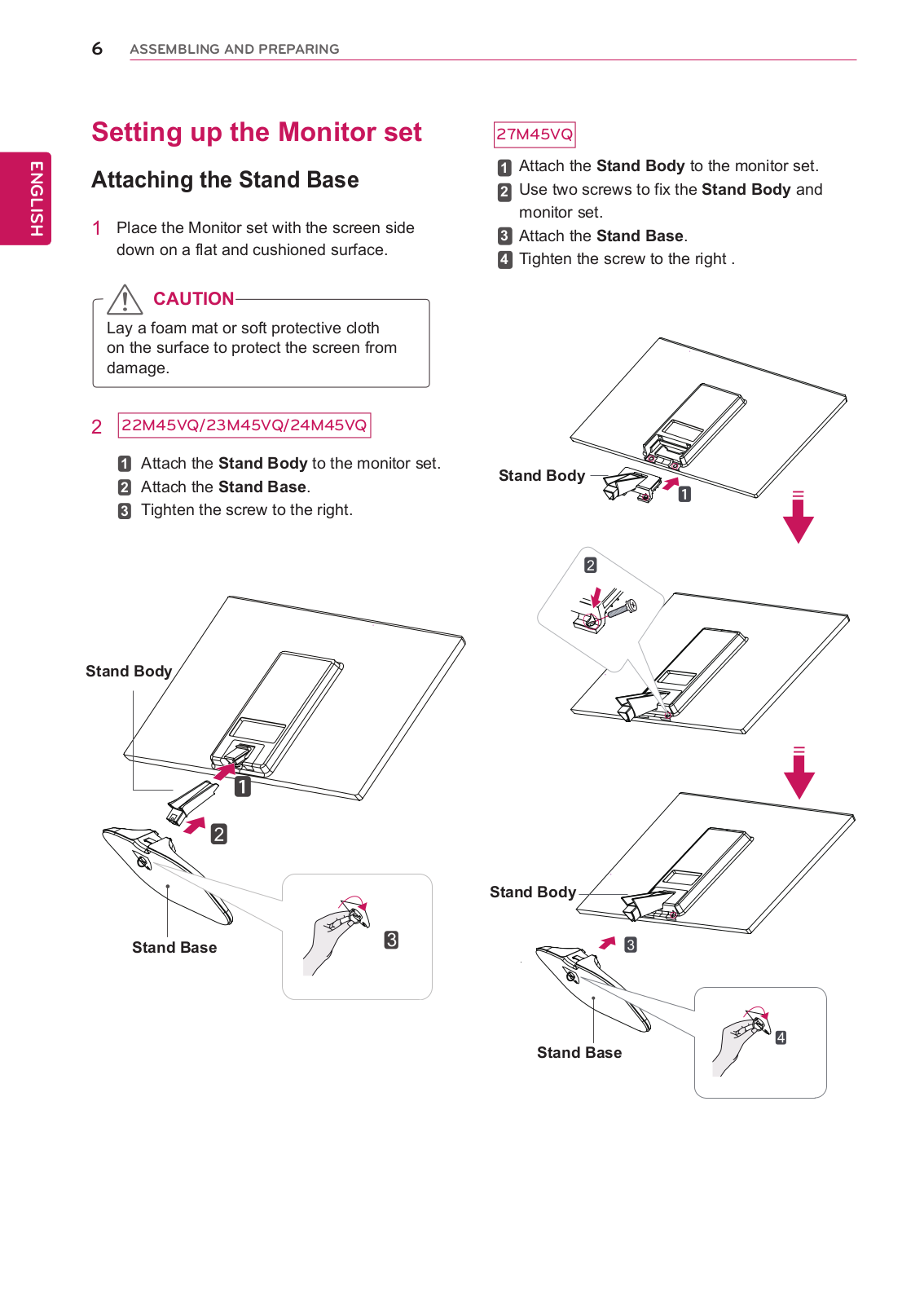
Owner’s Manual
32 pgs
11.28 Mb
0
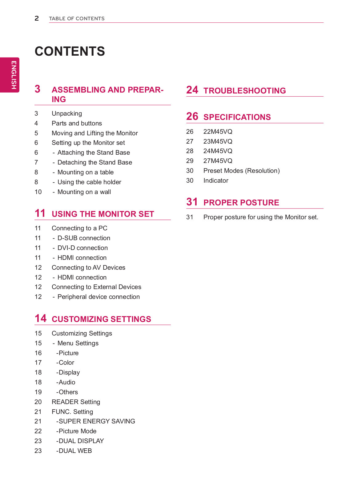
Table of contents
Loading...
LG 27M45VQ-B Owner’s Manual
...
LG Owner’s Manual
Download
Specifications and Main Features
Frequently Asked Questions
User Manual
Download
Loading...
+
22
hidden pages
Unhide
You need points to download manuals.
1 point = 1 manual.
You can buy points or you can get point for every manual you upload.
Buy points
Upload your manuals
 Loading...