

LG 27HJ710S-W Owner’s Manual

OWNER’S MANUAL
IPS LED
MONITOR
(LED Monitor*)
* LG LED Monitor applies LCD screen with LED backlights.
Please read this manual carefully before operating
your set and retain it for future reference.
27HJ710S
www.lg.com
Copyright ⓒ 2019 LG Electronics Inc. All Rights Reserved.

2
TABLE OF CONTENTS
ENGLISH
ON CLEANING ------------------------ 3
LICENSE ------------------------------- 3
ASSEMBLY AND PREPARING -------- 4
SETTINGS ---------------------------- 13
TROUBLESHOOTING ---------------- 25
PRODUCT SPECIFICATIONS -------- 27
EXTERNAL CONTROLLER SETUP -- 31

3
ON CLEANING
Recommended Cleaning Chemicals
Isopropanol 100%
Ethanol 70%
®
Cidex
OPA
0.9% NaCl solution
How to Use Cleaner
Prior to cleaning, turn off the monitor and remove the power cable.
Soak a soft cloth in a recommended cleaner, then lightly rub the screen with no more than 1 N of force.
The cleaner could cause serious damage if it leaks inside the monitor while cleaning.
Do not clean the screen’s LCD panel as it may be damaged. Clean the other parts of the monitor.
Do not use benzene, thinner, acids or alkaline cleaners or other such solvents.
Cleaning guidelines for displays must only be carried out by medical professionals (doctors or nurses) and must not
be handled by patients.
LICENSE
Each model has different licenses. Visit www.lg.com for more information on the license.
ENGLISH
The terms HDMI and HDMI High-Definition Multimedia Interface, and the HDMI
logo are trademarks or registered trademarks of HDMI Licensing LLC in the United
States and other countries.
VESA, VESA logo, DisplayPort compliance logo and DisplayPort compliance logo for
dual-mode source devices are all registered trademarks of the Video Electronics
Standards Association.
The SuperSpeed USB Trident logo is a registered trademark of USB Implementers
Forum, Inc.
4
ASSEMBLY AND PREPARING
ENGLISH
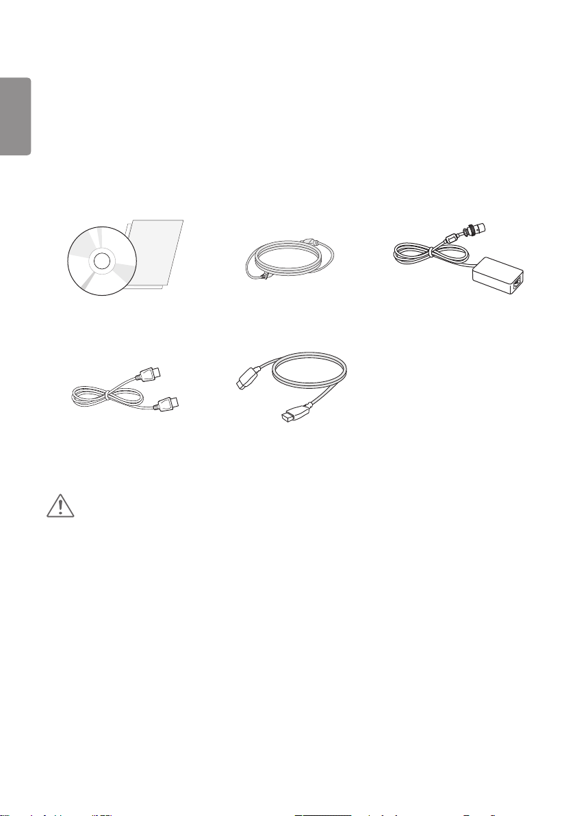
Product Composition
Please check whether all the components are included in the box before using the product. If there are any missing
components, contact the retailer where you purchased the product. Note that the product and related components
may look different from those shown here.
CD (Owner’s Manual / Software /
Guides) / Cards
DisplayPort Cable
Power Cord AC/DC Adaptor
HDMI Cable
CAUTION
Always use genuine LG components to ensure safety and product performance.
The product warranty will not cover damage or injury caused by the use of unauthorized components.
It is recommend that use the supplied components.
If you use generic cables not certified by LG, the screen may not display or there may be image noises.
5
NOTE
The components may look different from those illustrated here.
Without prior notice, all product information and specifications contained in this manual are subject to change to
improve the performance of the product.
To purchase optional accessories, visit an electronics store or an online shopping site, or contact the retailer from
which you purchased the product.
The power cord provided may differ depending upon the region.
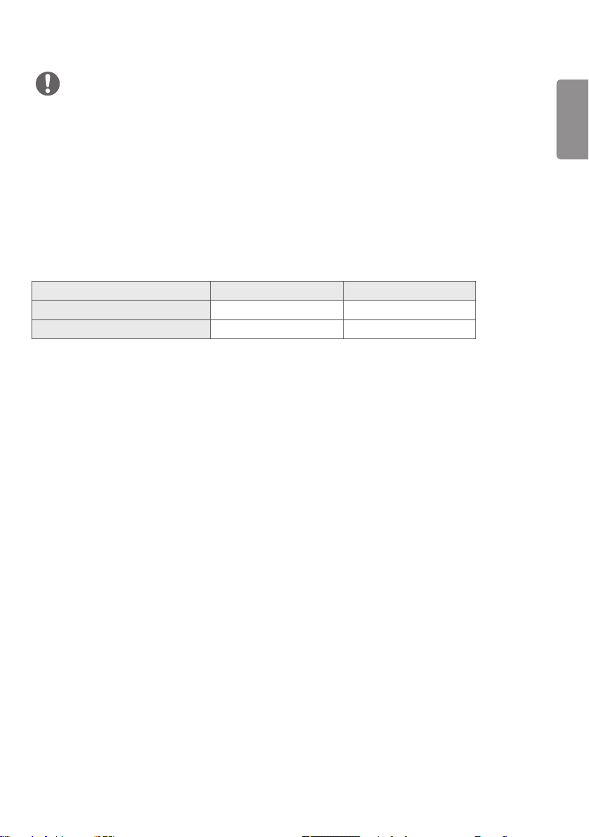
Supported Drivers and Software
Check the drivers and software supported by your product and refer to the manuals on the CD enclosed in the product
package.
Drivers and Software Installation Priority 27HJ710S
Monitor Driver Recommended O
True Color Pro Optional O
Required and Recommended: You can download and install the latest version from the enclosed CD or from the LGE
website (www.lg.com).
Optional: You can download and install the latest version from the LGE website (www.lg.com).
ENGLISH
6
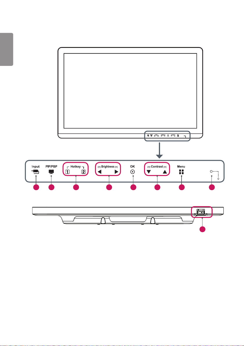
Product and LED Control buttons
ENGLISH
1 2 5 7 8 3 6 4
9
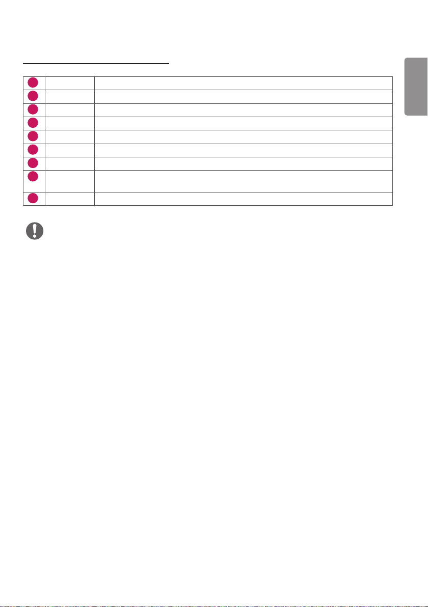
LED Control button Functions
1
Input Selects the input mode.
2
PIP/PBP Displays the screens of two input modes on one monitor.
3
Hotkey 1, 2 Opens the Hot key Settings menu.
4
Brightness Adjusts the screen brightness.
5
OK Selects menus or options and confirms.
6
Contrast Adjusts the screen contrast.
7
Menu Displays LED Control buttons on the front panel and opens the menu mode.
8
Power
indicator
9
Power switch Turns the power on/off.
NOTE
The Power button is located at the bottom right on the front of the monitor.
If the Control Key LED is turned off, press the Control Key [Menu] button to turn the Control button LED on. When
the Control Key LED is turned on, you can control the Control Key functions.
The green indicator illuminates if the power is on. The arrow indicates the position of the
power switch.
7
ENGLISH
8
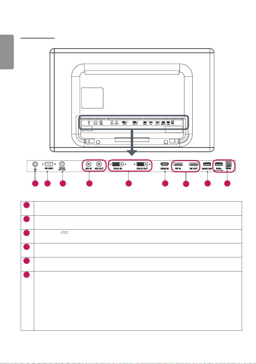
Connectors
ENGLISH
1 2 3 4 5 6
1
Potential Equalization Conductor
- Connect an equipotential plug.
2
RS-232C Connector
- Connect to an external device through the RS-232C connector and control the monitor.
3
DC-IN (19 V ) Connector
- Connect the AC/DC adaptor.
4
SDI IN / SDI OUT Connector
- Receives or transmits serial digital component signals.
5
DVI-D IN / DVI-D OUT Connector
- Receives or transmits digital video signals.
6
HDMI IN Connector
- Receives digital video signals.
- DVI to HDMI/DP (DisplayPort) to HDMI cables may cause compatibility issues.
Make sure to use certified cables that bear the HDMI logo. If you do not use a certified HDMI cable, the
screen may not display, or a connection error may occur.
►Recommended HDMI cable types
- High-speed HDMI®/TM cables
- High-speed HDMI®/TM Ethernet cables
7
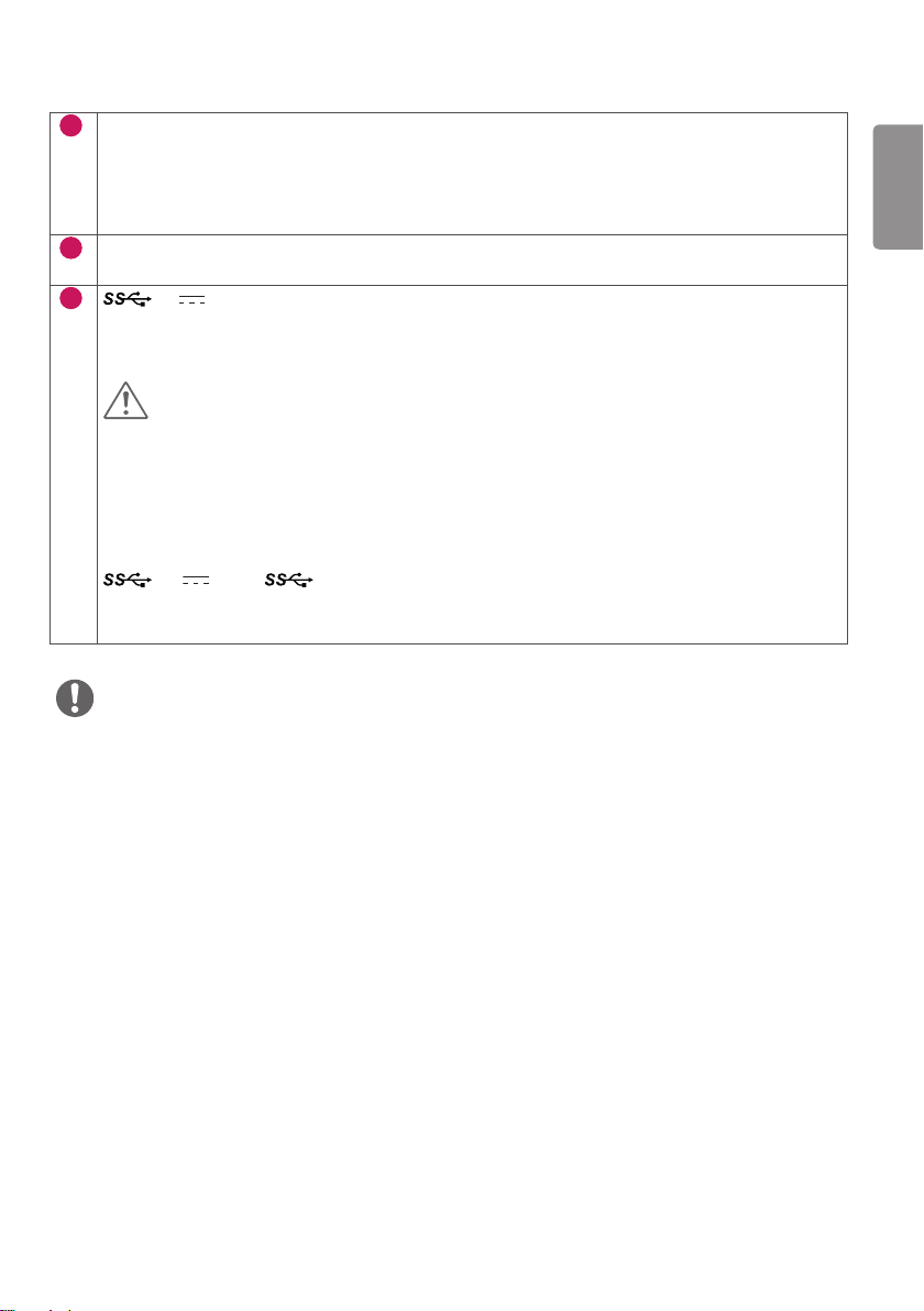
9 8
7
DP IN / DP OUT Connector
- Receives or transmits digital video signals.
- There may be no video output depending on the DP (DisplayPort) version of your PC.
- A cable with DisplayPort 1.2 specifications is recommended when using a Mini DP to DP (Mini DisplayPort
to DisplayPort) cable.
8
SERVICE ONLY Connector
- The USB port is used for service only.
9
5 V 0.9 A (USB Connector)
- Used for HW Calibrator (Optional Accessory) connection.
- A keyboard, mouse or USB device can be connected.
CAUTION
Precautions for Using USB Storage Devices
A USB storage device installed using an automatic recognition program or its own driver may not be
recognizable.
Some USB devices may not be supported or may not work properly.
It is recommended that you use a USB hub or hard disk drive with power supplied. (If insufficient power is
supplied, the USB storage device may not be detected properly)
5 V 0.9 A / (USB Connector)
- Connect your accessory to the USB input port.
- To use USB 3.0, connect a USB 3.0 Type A-B cable to your PC.
NOTE
All signal OUT connectors (SDI, DVI, DP) output signals when the monitor's power switch is on. Signals are not output
when the power switch is off.
This monitor supports the *Plug and Play feature.
* Plug and Play: A feature that allows you to add a device to your computer without having to reconfigure anything or
install any manual drivers.
The standard of the DVI and the SDI output terminals for transmitting a screen
- DVI OUT: Connect a 5-meter cable to transmit a copied screen to a monitor.
- SDI OUT: Connect a 100-meter cable (BELDEN 1694) to transmit a copied screen to a monitor.
9
ENGLISH
10
Installing the Monitor
ENGLISH
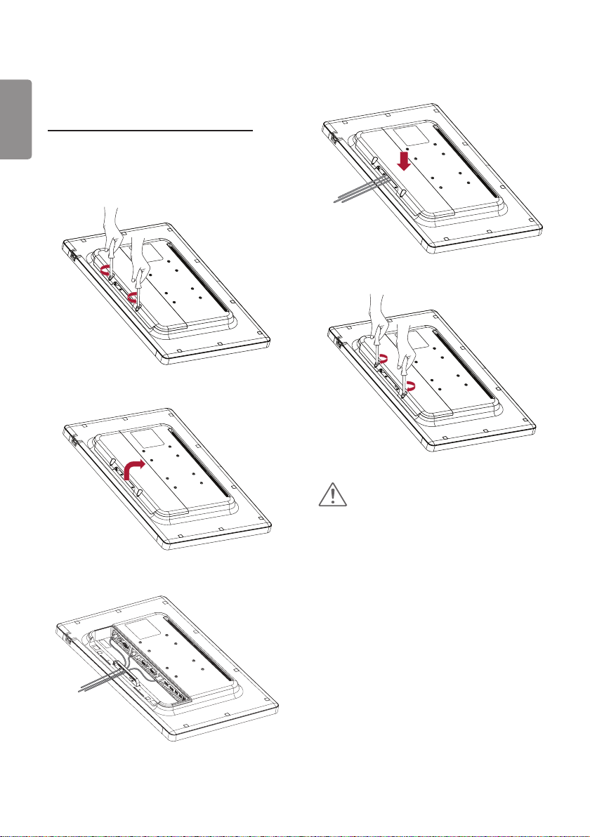
Cable connection and organize
Before connecting the connectors, remove the back
door as shown below.
1
2
4
5
CAUTION
When the back door is attached to the monitor, the
monitor meets water resistance standards. Do not
use the monitor with the back door detached, as the
water resistance capability is not guaranteed without
3
the door.
11
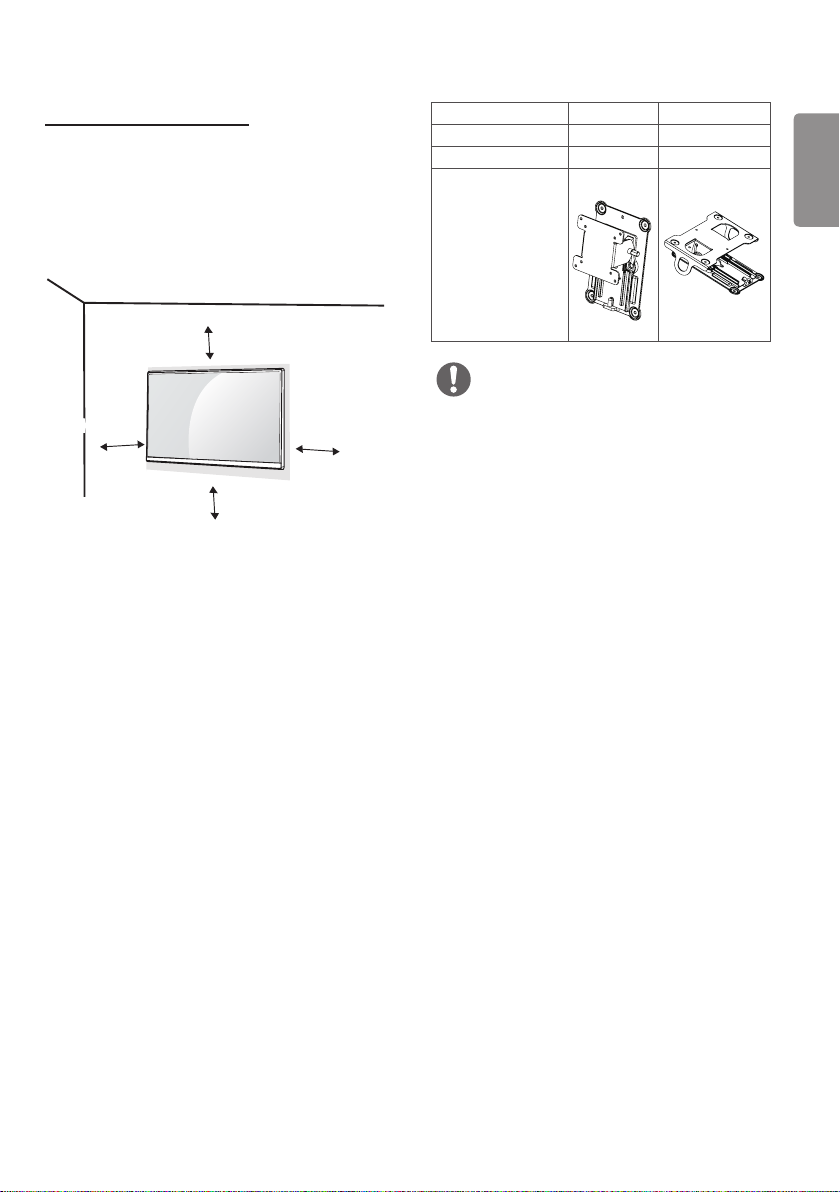
Installing on the Wall
Install the monitor at least 100 mm away from the
wall on each side of the monitor to ensure sufficient
ventilation. Detailed installation instructions can be
obtained from your local dealer. Please refer to the
manual to install and set up a tilting wall mounting
bracket.
100 mm
100 mm
100 mm
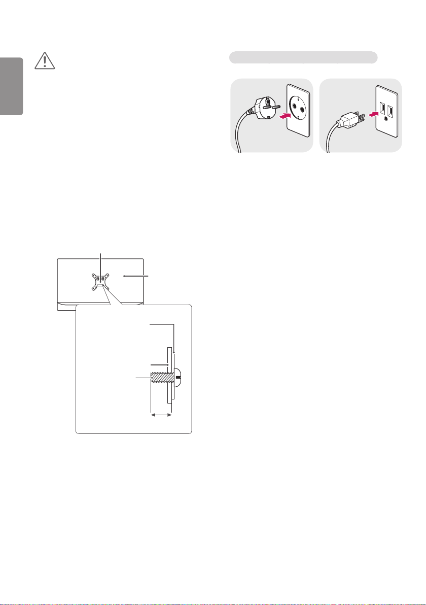
To install the monitor to a wall, attach a wall mount
plate (optional) to the back of the monitor.
Make sure that the wall mount plate (optional) is
securely fixed to the monitor and to the wall.
100 mm
1 Using screws longer than the standard length may
damage the inside of the product.
2 A non-VESA standard screw may damage
the product and cause the monitor to fall. LG
Electronics is not liable for any accidents relating to
the use of non-standard screws.
Wall Mount (mm)
Standard screw
Required screws
Wall Mount Plate
(optional)
100 x 100 200 x 100
M4 x L10 M4 x L10
4 4
RW120 RW240
NOTE
wall mount screw holes on the back of the monitor.
Use the screws specified by VESA standards.
The wall mount kit includes an installation manual and
the necessary parts.
The wall mount plate is an optional item. You can
obtain additional accessories from your local dealer.
The length of screws may differ depending on the wall
mount. Be sure to use the proper length.
For more information, please refer to the manual for
the wall mounting bracket.
ENGLISH
12
ENGLISH
CAUTION
Disconnect the power cord first. Then move or install
the monitor. There is risk of electric shock.
Installing the monitor on the ceiling or on a slanted
wall may result in the monitor falling off, which could
lead to injury. Use an authorized LG wall mount and
contact the local dealer or qualified personnel.
Applying excessive force when tightening screws may
damage the monitor. Such damage is not covered by
the product warranty.
Use the wall mounting bracket and screws that
confirm to VESA standards. Damage caused by the
use or misuse of inappropriate components is not
covered by the product warranty.
When measured from the back of the monitor, the
length of each installed screw must be 8 mm or less.
Wall mount plate
Wall mount plate
Precautions for Connecting the Power Cord
100-240 V ~
Make sure to use the power cord that is provided in
the product package. Connect the cord to a grounded
power outlet.
If you need another power cord, please contact your
local dealer or the nearest retail store.
Back of the
monitor
Back of the monitor
Screw
specifications
: M4 x L10
Max. 8 mm
13
SETTINGS
Activate Main Menu
1 Press the [Menu] button to activate the LED Control button. Pressing the [Menu] button while the LED Control
button is activated brings up the OSD menu.
2 Use the [ Brightness ] left/right and [ Contrast ] up/down LED Control buttons to navigate.
3 Press the [Menu] or [ Brightness] LED Control button to exit the OSD menu.
CAUTION
• The actual On Screen Displays (OSD) that appear on your monitor may differ from those shown in this manual.
ENGLISH
14
QUICK SETTINGS
ENGLISH
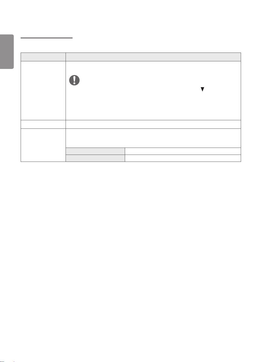
The following settings are available.
Quick Settings Description
Brightness
Contrast
Hot key Settings Assigns hotkeys for picture settings. Once configured, the assigned menu is activated when
Adjusts the brightness of the screen.
NOTE
You can turn the Brightness Stabilization to On/ Off by pressing the button in the
Brightness menu.
When the Brightness Stabilization is On, Brightness menus becomes disabled.
When the Brightness Stabilization is On, SMART ENERGY SAVING and DFC menus
become disabled.
Adjusts the color contrast of the screen.
a hotkey is pressed. (PIP Size, Mono, Color Temp, Gamma, Black Stabilizer, Screen Zoom,
Off)
Hotkey 1 Assigns a function to Hotkey 1.
Hotkey 2 Assigns a function to Hotkey 2.
 Loading...