

LG 27EB22PY User Manual [ru]

OWNER’S MANUAL
ENGLISH
IPS LED MONITOR
Please read this manual carefully before operating your set and
retain it for future reference.
IPS LED MONITOR MODEL
27EB22PY
www.lg.com
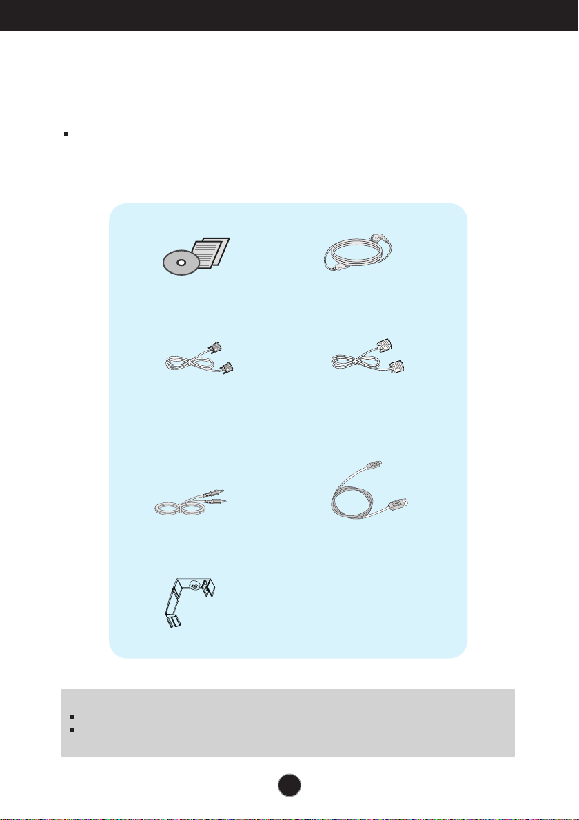
Accessories
!!! Thank for selecting LGE products !!!
Please make sure the following items are included with your
monitor. If any items are missing, contact your dealer.
User's Guide/Cards
DVI-D Signal Cable
(This feature is not available in all
countries.)
Audio Cable
Cable Holder
Power Cord
15-pin D-Sub Signal Cable
(To set it up, this signal cable may be
attached to this product before
shipping out.)
USB Cable
NOTE
This accessories may look different from those shown here.
User must use shielded signal interface cables (D-sub 15 pin cable, DVI-D cable) with ferrite
cores (core in the connector) to maintain standard compliance for the product.
1
Connecting the Display
2
.
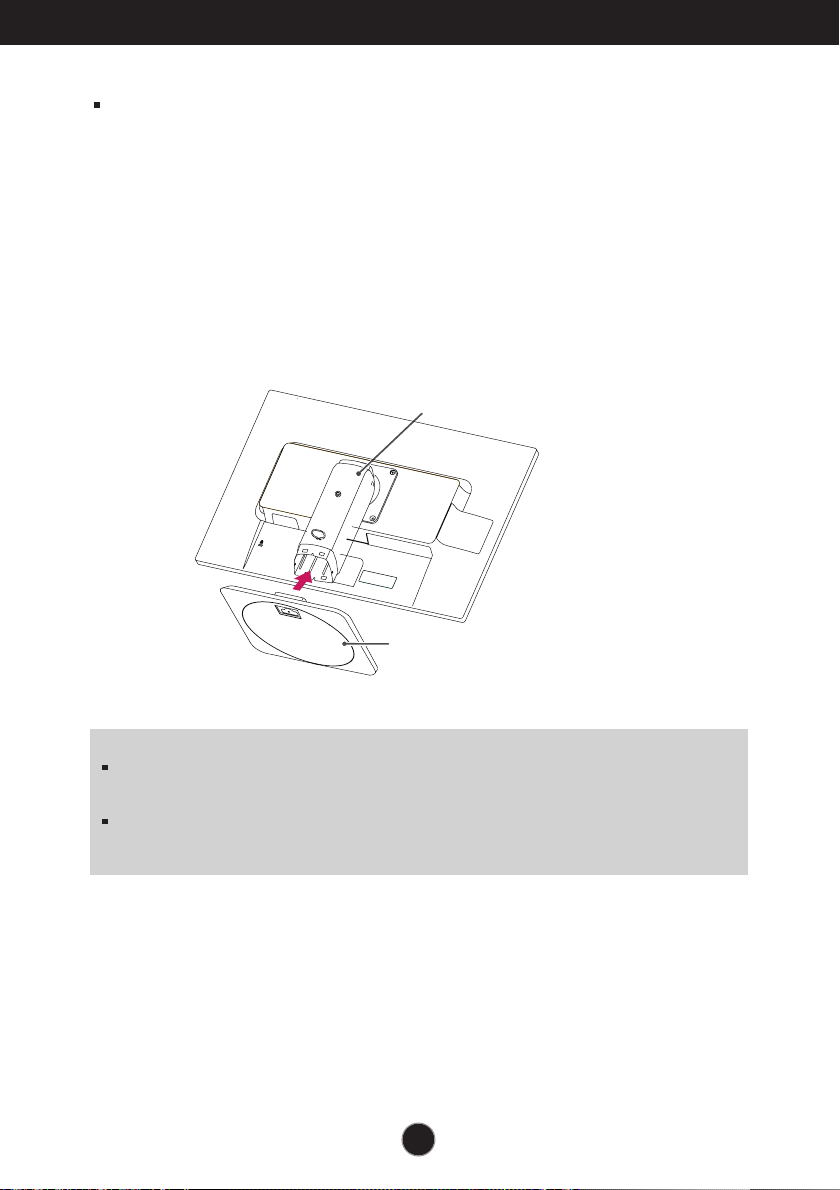
Assemble the Stand Base into the Stand Body.
Be sure don't pull out the Stop Pin and make the Stand Base direction as shown.
WARNING
The tape and locking pin may only be removed from those monitors equipped with a
standing base when the base is pulled up. Otherwise, you may be injured by the protruding
sections of the stand.
Product Handling with Care: When you lift up or move the product, Do Not hold or touch the
front part of LCD panel. It will damage the panel. (Please hold the Stand Body or plastic cover of
the product.)
Before setting up the monitor, ensure that the power to the monitor,
the computer system, and other attached devices are turned off.
Connecting the stand base
1. Place the monitor with its front facing downward on a cushion or soft cloth.
Stand Body
Stand Base
2
Connecting the Display
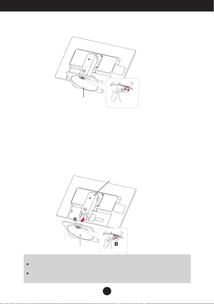
3. Use a coin on the back of the stand base and turn the screw clockwise to tighten.
Stand Base
4.
Lift and turn the monitor to face towards the front after the connection is
made to the female part of the cable you're attaching.
Removing the stand base
1. Place the monitor with its front facing downward on a cushion or soft cloth.
2. When you desire to disintegrate the monitor from the stand base, use a coin to turn the
screw counterclockwise.
Stand Body
Stand Base
IMPORTANT
This illustration depicts the general model of connection. Your monitor may differ from the items
shown in the picture.
Do not carry the product upside down holding only the stand base. The product may fall and get
damaged or injure your foot.
3
Connecting the Display
* Please be sure to
remove the Locking
pin to adjust the height.
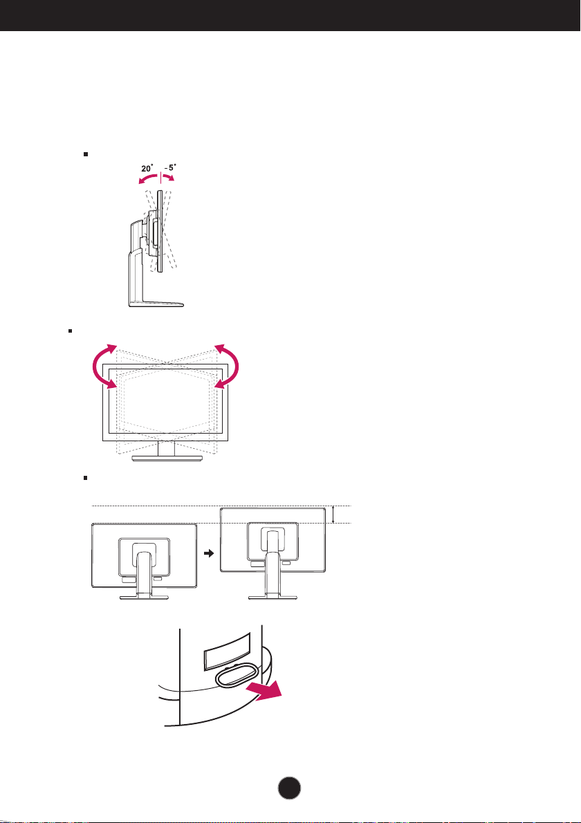
Positioning your display
After installation, adjust the angle as shown below.
1. Adjust the position of the panel in various ways for maximum comfort.
Tilt Range
Swivel Range : 355˚
Height Range : maximum 5.12 inches (130.0 mm)
4
130.0mm

Connecting the Display
When adjusting the angle of the screen, do not put your finger(s) in
between the head of the monitor and the stand body. You can hurt your
finger(s).
When adjusting the height of the screen, do not put your finger(s) in
between the head of the monitor and the stand base. You can hurt your
finger(s).
WARNING
You do not need to replace the Locking pin after it is removed, to adjust its height.
ERGONOMIC
t is recommended that in order to maintain an ergonomic and comfortable viewing position, the forward tilt
I
angle of the monitor should not exceed 5 degrees.
5
Connecting the Display
Stand section
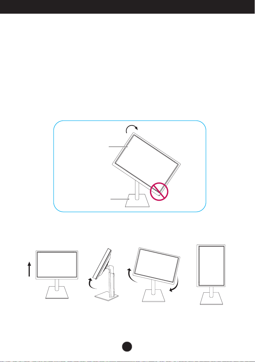
Using the Pivot function
-The pivot function allows you to rotate the screen 90 degrees clockwise.
1.
Lift the monitor to its highest height to utilize the Pivot function.
2.Landscape & Portrait : You can rotate the panel 90
Please be cautious and avoid contact between the monitor head and the
Stand Base when rotating the screen to access the Pivot function. If the
monitor head touches the Stand Base, then the Stand Base could crack.
Head section
.
3
Be careful with the cables when rotating the screen.
o
clockwise.
6
Connecting the Display
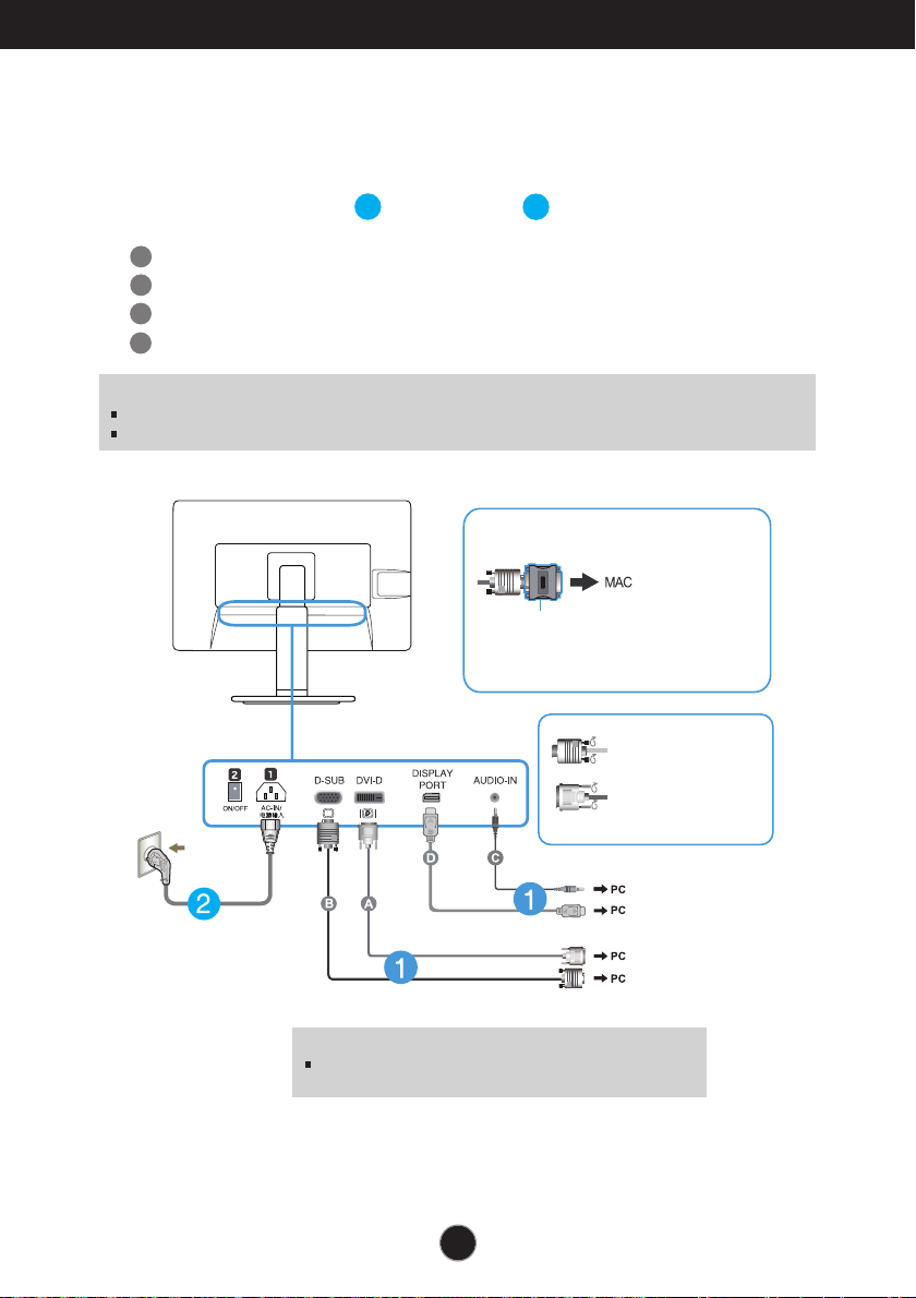
Connecting with the PC
1. Before setting up the monitor, ensure that the power to the monitor, the computer
system, and other attached devices is turned off.
2.
Connect signal input cable and power cord in order, then tighten the screw
of the signal cable.
A
Connect DVI-D(Digital signal) Cable
B
Connect D-sub(Analog signal) Cable
C
Connect Audio Cable
D
Connect DisplayPort Cable (Separate purchase)
NOTE
This is a simplified representation of the rear view.
This rear view represents a general model; your display may differ from the view as shown.
1
2
When using a D-Sub signal input cable
connector for Macintosh
Mac adapter : For Apple Macintosh use, a
separate plug adapter is needed to change the
15 pin high density (3 row) D-sub VGA
connector on the supplied cable to a 15 pin 2
row connector.
Varies according to model.
Wall-outlet type
Connect the signal
input cable and tighten
it up by turning in the
direction of the arrow
as shown in the figure.
DVI-D (This feature is not available in all countries.)
Warning
Please pull the DVI cable first,then pull DisplayPort cable,
for protect your finger.
7

Connecting the Display
3. Put the power cord and cables into the cable holder.
4. Press the power button on the front panel to turn the power on. When monitor power is
turned on, the 'Self Image Setting Function' is executed automatically.
(Only Analog Mode)
Power Button
NOTE
‘ Self Image Setting Function’? This function provides the user with optimal display
settings.When the user connects the monitor for the first time, this function automatically adjusts
the display to optimal settings for individual input signals.
‘AUTO’ Function? When you encounter problems such as blurry screen, blurred letters, screen
flicker or tilted screen while using the device or after changing screen resolution, press the
AUTO function button to improve resolution.
8
 Loading...