

LG Electronics 26LT670H, 32LT670H, 37LT670H, 42LT670H User Manual

26LT670H 32LT670H 37LT670H 42LT670H
55LS675H
Lodging Guest Interactive Pro:Centric ® TVs
Commercial Mode Setup Guide
Note: Selected features shown in this guide may not be available on all models.
EXPERIENCED INSTALLER
Automated Installation Routine Wizard
pages 11 – 13
© Copyright 2013 LG Electronics U.S.A., Inc.
Custom Master TV Setup
pages 14 – 17
Cloning Information
pages 28 – 36
FTG Mode of Operation
pages 37 – 48
P/N: 206-4213 (Rev F)
For Customer Support/Service, please call:
1-888-865-3026
The latest product information and documentation is
available online at:
www.LGsolutions.com
MODEL and SERIAL NUMBER
The model and serial numbers of this TV are located on the
back of the cabinet. For future reference, LG suggests that
you record those numbers here:
Model No._________________ Serial No._______________
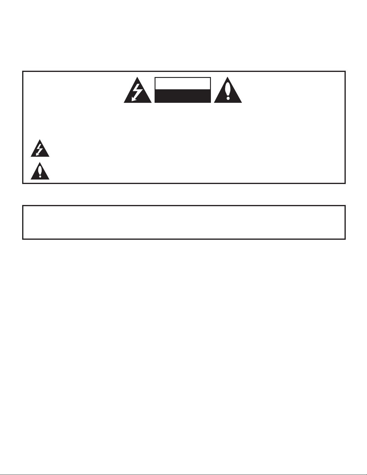
WARNING
RISK OF ELECTRIC SHOCK
DO NOT OPEN
WARNING:
TO REDUCE THE RISK OF ELECTRIC SHOCK DO NOT REMOVE COVER (OR BACK). NO USERSERVICEABLE PARTS INSIDE. REFER TO QUALIFIED SERVICE PERSONNEL.
The lightning flash with arrowhead symbol, within an equilateral triangle, is intended to alert the user to
the presence of uninsulated “dangerous voltage” within the product’s enclosure that may be of sufficient
magnitude to constitute a risk of electric shock to persons.
The exclamation point within an equilateral triangle is intended to alert the user to the presence of important
operating and maintenance (servicing) instructions in the literature accompanying the appliance.
WARNING:
TO PREVENT FIRE OR SHOCK HAZARDS, DO NOT EXPOSE THIS PRODUCT TO RAIN OR MOISTURE.
POWER CORD POLARIZATION (LT670H SERIES ONLY):
This product is equipped with a 3-wire grounding-type alternating current power plug. This plug will fit into the
power outlet only one way. This is a safety feature. If you are unable to insert the plug fully into the outlet, contact
your electrician to replace your obsolete outlet. Do not defeat the safety purpose of the 3-wire grounding-type plug.
NOTE TO CABLE/TV INSTALLER:
This reminder is provided to call the cable TV system installer’s attention to Article 820-40 of the National Electrical
Code (U.S.A.). The code provides guidelines for proper grounding and, in particular, specifies that the cable ground
shall be connected to the grounding system of the building, as close to the point of the cable entry as practical.
REGULATORY INFORMATION:
This equipment has been tested and found to comply with the limits for a Class B digital device, pursuant to Part 15 of
the FCC Rules. These limits are designed to provide reasonable protection against harmful interference when the
equipment is operated in a residential installation. This equipment generates, uses and can radiate radio frequency
energy and, if not installed and used in accordance with the instruction manual, may cause harmful interference to radio
communications. However, there is no guarantee that interference will not occur in a particular installation. If this equipment does cause harmful interference to radio or television reception, which can be determined by turning the equipment off and on, the user is encouraged to try to correct the interference by one or more of the following measures:
• Reorient or relocate the receiving antenna.
• Increase the separation between the equipment and receiver.
• Connect the equipment to an outlet on a circuit different from that to which the receiver is connected.
• Consult the dealer or an experienced radio/TV technician for help.
CAUTION:
Do not attempt to modify this product in any way without written authorization from LG Electronics U.S.A., Inc.
Unauthorized modification could void the user’s authority to operate this product.
COMPLIANCE:
The responsible party for this product’s compliance is: LG Electronics U.S.A., Inc.
1000 Sylvan Avenue, Englewood Cliffs, NJ 07632, USA • Phone: 1-201-816-2000
Marketed and Distributed in the United States by LG Electronics U.S.A., Inc.
1000 Sylvan Avenue, Englewood Cliffs, NJ 07632
2
© Copyright 2013 LG Electronics U.S.A., Inc.
206-4213

IMPORTANT SAFETY INSTRUCTIONS
1. Read these instructions.
2. Keep these instructions.
3. Heed all warnings.
4. Follow all instructions.
5. Do not use this apparatus near water.
6. Clean only with dry cloth.
7. Do not block any ventilation openings. Install in accordance with the manufacturer’s instructions.
8. Do not install near any heat sources, such as radiators,
heat registers, stoves, or other apparatus (including
amplifiers) that produce heat.
9. Do not defeat the safety purpose of the polarized or
grounding-type plug. A polarized plug has two blades
with one wider than the other. A grounding-type plug
has two blades and a third grounding prong. The wide
blade or the third prong are provided for your safety. If
the provided plug does not fit into your outlet, consult
an electrician for replacement of the obsolete outlet.
10. Protect the power cord from being walked on or pinched,
particularly at plugs, convenience receptacles, and the
point where it exits from the apparatus.
11. Only use attachments/accessories specified by the
manufacturer.
12. Use only with the cart, stand, tripod, bracket, or table
specified by the manufacturer or sold with the apparatus.
When a cart is used, use caution when moving the cart/
apparatus combination in order to avoid injury from
tip-over.
PORTABLE CART WARNING
13.
Refer all servicing to qualied service personnel.
Servicing is required when the apparatus has been
damaged in any way, such as power-supply cord or
plug is damaged, liquid has been spilled or objects
have fallen into the apparatus, the apparatus has been
exposed to rain or moisture, does not operate normally,
or has been dropped.
14. Never touch this apparatus or antenna during a thunder or
lightning storm.
15. When mounting a TV on the wall, make sure not to install
the TV by the hanging power and signal cables on the back
of the TV.
16. Do not allow an impact shock or any objects to fall into the
product, and do not drop objects onto the screen.
17. Power Cord
Caution: It is recommended that appliances be placed
upon a dedicated circuit; that is, a single outlet circuit
which powers only that appliance and has no additional
outlets or branch circuits. Check the TV specifications to
be certain.
Periodically examine the cord of your appliance, and if its
appearance indicates damage or deterioration, unplug it,
discontinue use of the appliance, and have the cord replaced
with an exact replacement part by an authorized servicer.
Protect the power cord from physical or mechanical abuse,
such as twisting, kinking, or pinching or being closed in a
door or walked upon. Pay particular attention to plugs, wall
outlets, and the point where the cord exits the appliance.
Do not use a damaged or loose power cord. Be sure to grasp
the plug when unplugging the power cord. Do not pull on the
power cord to unplug the TV.
18. Overloading
Do not connect too many appliances to the same AC power
outlet as this could result in fire or electric shock. Do not
overload wall outlets. Overloaded wall outlets, loose or
damaged wall outlets, extension cords, frayed power cords,
or damaged or cracked wire insulation are dangerous. Any of
these conditions could result in re or electric shock.
19. Outdoor Use/Wet Location
Warning: To reduce the risk of re or electrical
shock, do not expose this product to rain,
moisture or other liquids.
Do not touch the TV with wet hands. Do not install this product
near ammable objects such as gasoline or candles or expose
the TV to direct air conditioning.
Do not expose to dripping or splashing and do not place
objects lled with liquids, such as vases, cups, etc., on or over
the apparatus (e.g., on shelves above the unit).
20. Grounding
Ensure that you connect the earth ground wire to prevent
possible electric shock (i.e., a TV with a three-prong grounded
AC plug must be connected to a three-prong grounded AC
outlet). If grounding methods are not possible, have a qualied electrician install a separate circuit breaker. Do not try to
ground the unit by connecting it to telephone wires, lightning
rods, or gas pipes.
21. Disconnect Device
The mains plug is the disconnecting device. The plug must
remain readily operable.
As long as this unit is connected to the AC wall outlet, it is not
disconnected from the AC power source even if you turn off
this unit by SWITCH.
(Continued on next page)
206-4213
3
IMPORTANT SAFETY INSTRUCTIONS
(Continued from previous page)
22. Outdoor Antenna Grounding
If an outside antenna or cable system is connected to the
product, follow the precautions below.
An outdoor antenna system should not be located in the
vicinity of overhead power lines or other electric light or power
circuits or where it can come into contact with such power
lines or circuits as death or serious injury can occur.
Be sure the antenna system is grounded so as to provide
some protection against voltage surges and built-up static
charges.
Article 810 of the National Electrical Code (NEC) in the U.S.A.
provides information with respect to proper grounding of the
mast and supporting structure, grounding of the lead-in wire
to an antenna-discharge unit, size of grounding conductors,
location of antenna-discharge unit, connection to grounding
electrodes, and requirements for the grounding electrode.
Antenna Grounding According to NEC, ANSI/NFPA 70
Ground Clamp
Electric Service
Equipment
Antenna Lead in Wire
Antenna Discharge Unit
(NEC Section 810-20)
Grounding Conductor
(NEC Section 810-21)
Ground Clamps
Power Service Grounding
Electrode System (NEC
Art 250, Part H)
23. Cleaning
When cleaning, unplug the power cord and wipe gently with
a soft cloth to prevent scratching. Do not spray water or other
liquids directly on the TV as electric shock may occur. Do not
clean with chemicals such as alcohol, thinners or benzene.
24. Transporting Product
Make sure the TV is turned Off and unplugged and that all
cables have been removed. It may take two or more people
to carry larger TVs. Do not press against or put stress on the
front panel of the TV during transport.
25. Ventilation
Install the TV where there is proper ventilation. Do not install
in a conned space such as a bookcase. Do not cover the TV
with cloth or other materials (e.g., plastic) while it is plugged
in. Do not install in excessively dusty places.
26. Do not touch the ventilation openings, as they may become
hot while the TV is operating.
27. If you smell smoke or other odors coming from the TV or
hear strange sounds, unplug the power cord, and contact an
authorized service center.
28. Do not press against the front panel of the TV with your
hand or a sharp object (e.g., a nail, pencil, or pen) or make a
scratch on it.
29. Keep the product away from direct sunlight.
30. Dot Defect
The LCD panel is a high technology product with resolution
of two million to six million pixels. In a very few cases, you
could see ne dots on the screen while you are viewing the
TV. Those dots are deactivated pixels and do not affect the
performance and reliability of the TV.
31. Generated Sound
“Cracking”: A cracking noise that occurs while the TV is
On or when it is turned Off is generated by plastic thermal
contraction due to temperature and humidity. This noise is
common for products where thermal deformation is required.
Electrical circuit humming/panel buzzing: A low level noise is
generated from a high-speed switching circuit, which supplies
a large amount of current to operate a product. It varies
depending on the product. This generated sound does not
affect the performance and reliability of the product.
32. For LCD TV
If the TV feels cold to the touch, there may be a small “icker”
when it is turned On. This is normal; there is nothing wrong
with the TV. Some minute dot defects may be visible on the
screen, appearing as tiny red, green, or blue spots. However,
they have no adverse effect on the TV’s performance. Avoid
touching the LCD screen or holding your nger(s) against it for
long periods of time. Doing so may produce some temporary
distortion effects on the screen.
4
206-4213

Table of Contents
Safety Warnings . . . . . . . . . . . . . . . . . . . . . . . . . . . . . . . . . . 2
Important Safety Instructions . . . . . . . . . . . . . . . . . . . . . . 3 – 4
Table of Contents . . . . . . . . . . . . . . . . . . . . . . . . . . . . . . . . . 5
Commercial Mode Overview . . . . . . . . . . . . . . . . . . . . . 6 – 8
Setup Checklist . . . . . . . . . . . . . . . . . . . . . . . . . . . . . . . . . 6
Pass-through Mode. . . . . . . . . . . . . . . . . . . . . . . . . . . . . . 6
FTG Mode. . . . . . . . . . . . . . . . . . . . . . . . . . . . . . . . . . . . . 8
Remote Management in FTG Mode . . . . . . . . . . . . . . . . . 8
Pro:Centric Operation . . . . . . . . . . . . . . . . . . . . . . . . . 9 – 10
Pro:Centric TV Interactive Menu Features . . . . . . . . . . . . 9
Pro:Centric Interactive Menu Navigation . . . . . . . . . . . . . 9
Pro:Centric Setup . . . . . . . . . . . . . . . . . . . . . . . . . . . . . . 10
Automated Installation Routine Wizard . . . . . . . . . . 11 – 13
Pro:Centric Auto Configuration . . . . . . . . . . . . . . . . . . . . 11
Pro:Centric Manual Configuration. . . . . . . . . . . . . . . . . . 12
USB Configuration . . . . . . . . . . . . . . . . . . . . . . . . . . . . . 13
Custom Master TV Setup. . . . . . . . . . . . . . . . . . . . . . 14 – 17
Before You Begin . . . . . . . . . . . . . . . . . . . . . . . . . . . . . . 14
Cloning Methods . . . . . . . . . . . . . . . . . . . . . . . . . . . . . . . 14
Clonable TV Setup Menu Features . . . . . . . . . . . . . . . . 14
Custom Master TV Setup Procedure . . . . . . . . . . . . . . . 15
Installer Menu . . . . . . . . . . . . . . . . . . . . . . . . . . . . . . . 18 – 26
Accessing the Installer Menu . . . . . . . . . . . . . . . . . . . . . 18
Using the Installer Menu . . . . . . . . . . . . . . . . . . . . . . . . . 19
Exiting the Installer Menu and Activating Updates . . . . . 19
Channel Icons / Custom Text Labels (2-5-4 +
MENU Mode) . . . . . . . . . . . . . . . . . . . . . . . . . . . . . . . . . . . 27
Cloning Overview . . . . . . . . . . . . . . . . . . . . . . . . . . . . . . . 28
USB Cloning Procedures. . . . . . . . . . . . . . . . . . . . . . 29
Learning / Teaching a Master TV Setup using
a USB Memory Device / .tlx File. . . . . . . . . . . . . . . . . . . 29
Learning / Teaching a Master TV Setup using
a USB Memory Device / .tll File . . . . . . . . . . . . . . . . . . .
Clone Programmer Cloning Procedures . . . . . . . . . 33
Learning / Teaching a Master TV Setup using
a TLL-1100A Clone Programmer . . . . . . . . . . . . . . . . . . 33
Learning / Teaching a Master TV Setup using
an LT2002 Clone Programmer . . . . . . . . . . . . . . . . . . . . 35
FTG Mode of Operation Overview . . . . . . . . . . . . . . 37
FTG Mode via CPU or EBL . . . . . . . . . . . . . . . . . . . . . . 37
Determining the TV Operating Mode . . . . . . . . . . . . . . . 38
–
–
–
32
31
36
38
FTG Mode via CPU . . . . . . . . . . . . . . . . . . . . . . . . . . . 39
Creating an FTG Configuration File using the
FTG File Manager. . . . . . . . . . . . . . . . . . . . . . . . . . . . . . 39
Teaching FTG Configuration to a TV . . . . . . . . . . . . . . . 41
Learning FTG Configuration from a TV . . . . . . . . . . . . . 42
Optional Manual Configuration / TV Setup . . . . . . . . . . . 43
FTG Mode via EBL (Local Configuration) . . . . . . . . . . . 44
FTG File Manager Utilities Overview . . . . . . . . . . . . . . 45 – 48
FTG File Manager Main Screen . . . . . . . . . . . . . . . . . . . 45
FTG Channel Map Configuration Utility . . . . . . . . . . . . . 46
FTG Channel Map Editor . . . . . . . . . . . . . . . . . . . . . . . . 47
FTG Installer Menu Configuration Utility. . . . . . . . . . . . . 48
Remote Jack Pack / TV Connections & Setup . . . . . . . 49
References
Upgrading TV/PTC Software using a USB Memory
Device. . . . . . . . . . . . . . . . . . . . . . . . . . . . . . . . . . . . . . . . . 50
Downloading a Splash Screen using a USB Memory
Device. . . . . . . . . . . . . . . . . . . . . . . . . . . . . . . . . . . . . . . . . 51
Power Consumption Settings . . . . . . . . . . . . . . . . . . . . . . . 52
TV Aux Input Configuration . . . . . . . . . . . . . . . . . . . . . . . . 53
b-LAN Setup & Overview . . . . . . . . . . . . . . . . . . . . . . . . . . 54
RJP Model List & Input Auto-sensing Hierarchy . . . . . . . . 55
Restoring Factory Defaults on the TV(s) . . . . . . . . . . . . . . 56
TV Zone Restrictions . . . . . . . . . . . . . . . . . . . . . . . . . . . . . 57
LT670H Rear and Side Jack Panels . . . . . . . . . . . . . . . . . 58
LS675H Rear and Side Jack Panels . . . . . . . . . . . . . . . . . 59
External Speaker Setup . . . . . . . . . . . . . . . . . . . . . . . . . . . 60
Installer Remote Control Typical Key Functions . . . . . . . . 61
Troubleshooting . . . . . . . . . . . . . . . . . . . . . . . . . . . . . . 62
General Troubleshooting. . . . . . . . . . . . . . . . . . . . . . . . . 62
Troubleshooting Flow Chart . . . . . . . . . . . . . . . . . . . . . . 63
Commercial Mode Check / FTG Operation
Troubleshooting . . . . . . . . . . . . . . . . . . . . . . . . . . . . . . . 64
Clone Programmer Troubleshooting. . . . . . . . . . . . . . . . 65
Glossary of Terms . . . . . . . . . . . . . . . . . . . . . . . . . . . . . . . 66
Document Revision History / Open Source Software Notice 67
Back Cover. . . . . . . . . . . . . . . . . . . . . . . . . . . . . . . . . . . . . 68
–
43
– 65
Notes
• Installer Menu content is intended for use primarily by qualied TV electronics technicians.
• Refer to the applicable Quick Reference Guide for additional information on TV installation, specications, maintenance, and safety instructions.
• Design and specications subject to change without prior notice.
206-4213
5

Commercial Mode Overview
This document describes how to set up LT670H and LS675H Pro:Centric ® TVs for Commercial Mode
operation. LG commercial TV functionality is based on “ownership” of the Channel Map; that is, the Channel
Map resides in the TV’s CPU, Protocol Translator Card (PTC), or embedded b-LAN™ (EBL) module, or it
resides externally from the TV (i.e., in a device from the solution provider).
These TV models are capable of Free-To-Guest (FTG) Mode operation via the TV CPU. Alternatively, the
EBL module can be configured either for Pass-through Mode (default) or FTG Mode. When neither the CPU
nor EBL is in FTG Mode, these TV models also allow external control via the TV’s MPI port.
Setup Checklist
Note: This document provides information specific to Commercial Mode operation. Refer to the Quick
Reference Guide for information on TV installation and hardware and cable connections.
Installation
__ Unpack TV and all accessories.
__ Install batteries in the Installer Remote.
__ Install TV on VESA mount or stand.
Note: It may be advisable to make all cable
connections before installing on VESA mount
or stand, as appropriate.
Hardware Connections
__ Install any additional hardware as
appropriate to your institution, LAN, etc.
Cable Connections
__ Make all rear jack panel and MPI card slot
connections, as appropriate.
Commercial Mode Setup
__ Complete appropriate procedures as described
in this document for Commercial Mode operation.
Pass-through Mode
This mode allows you to configure individual TVs for Pro:Centric or FTG Mode via CPU operation and/
or create a Master TV Setup for cloning purposes for TVs that are to remain in Pass-through Mode. This
mode also allows external control via the GAME CONTROL/MPI port on the TV rear jack panel.
There are two methods for configuring individual TVs that are currently in Pass-through Mode: either
using the Automated Installation Routine Wizard or the Custom Master TV Setup procedure as described
in this document.
Automated Installation Routine Wizard
The Automated Installation Routine Wizard provides Auto or Manual options for conguring essential
items for Pro:Centric operation and also provides an option for using a USB memory device to congure
the TV for FTG Mode via CPU. Use the Installer Remote to make selections and complete each step. See
“Automated Installation Routine Wizard” on pages 11 to 13 for detailed information.
Custom Master TV Setup
The Custom Master TV Setup procedure enables you to create a customized Master TV Setup for cloning
purposes. Use the Installer Remote to congure Installer Menu items as required for TV operation and
set up TV features (Channel, Picture, Audio, etc.). See “Custom Master TV Setup” on pages 14 to 17 for
detailed information.
6
206-4213
Installer Menu
To create a Master TV Setup, you will need to know how
to access the commercial controller (PTC) Installer Menu
and make changes to the default values as required. If
necessary, familiarize yourself with the Installer Menu and
how to make and save changes. Refer to pages 18 to 26
for information on accessing the Installer Menu and for
detailed descriptions of the Installer Menu items.
Commercial Mode Overview (Cont.)
xxLT670H PTC INSTALLER MENU
CPU-CTV
000 INSTALLER SEQ 000
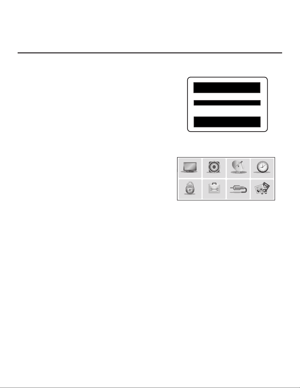
TV Setup Menus
On-screen setup menus control the features of the TV.
UPN 000-000-000-000 ASIC D279
PTC V1.00.009 CPU V3.17.00
Use the Installer Remote to access the TV setup menus,
and set the TV features to the desired configuration for
the end user.
Typical Installer Menu
Cloning
Cloning refers to the process of capturing a Master TV
Setup and transferring it to a Target TV. Both TVs must
be in Pass-through Mode and both TVs must be identical
models. The Master TV’s clonable setup menu features
PICTURE
should be configured as part of the Master TV Setup. If
there are features in the Master TV’s setup—channel
icons or labels, digital font options, etc.—that are not set
LOCK
or that are set incorrectly, those features also will not be
set or will be set incorrectly in the Target TVs. Refer to
pages 28 to 36 for detailed information on cloning
requirements and procedures.
External MPI Control
To control the TV using an external MPI control device, you must use the TV’s GAME
CONTROL/MPI port for communication purposes. In these TVs, Installer Menu item 118
POWER SAVINGS controls the power circuitry for both the embedded b-LAN module and
the GAME CONTROL/MPI port; therefore, to ensure that the GAME CONTROL/MPI port
circuitry is powered, thus enabling MPI communication, Installer Menu item 118 POWER
SAVINGS must be set appropriately. See Installer Menu item descriptions as well as
Reference section, “b-LAN Setup & Overview,” for further information.
Note: These TV models are not equipped with MPI card slots.
AUDIO
OPTION
TV Setup Menus
CHANNEL
INPUT
TIME
MY MEDIA
206-4213
7

Commercial Mode Overview (Cont.)
FTG Mode
This mode enables Pro:Idiom ® decryption and also allows logical channel mapping of physical channels
to remove the need for dash tuning. TV operation in FTG Mode is based on which element of the TV owns
the FTG Logical Channel Map—the CPU or the EBL. Understanding the application in which the TV will be
used is vital in determining the owner.
As indicated above, FTG mode operation in the LT670H and LS675H models can be provided either by
the TV CPU or the EBL. These are two separate and distinct FTG Modes of operation, each with its own
unique advantages and requirements as described later in this document. When the TV CPU is configured
with an FTG Channel Map, the CPU controls the operation of the TV, and when the EBL is configured with
an FTG Channel Map, the EBL controls the operation of the TV.
Once it is determined whether the TV CPU or the EBL will own the FTG Channel Map, conguration can
begin. Conguration of either requires a PC application—the LG FTG File Manager for the TV CPU or
the LG FTG Device Conguration Application for the EBL. Each application provides utilities that enable
you to create/edit an FTG Channel Map and congure Installer Menu settings. See pages 37 to 48 for
further information on FTG Mode operation and conguration.
Remote Management in FTG Mode
When the TV is configured for FTG Mode via CPU, remote management of the FTG Channel Map and
FTG Installer Menu settings is provided by a Pro:Centric server. Refer to the Pro:Centric Server Admin
Client User Guide for further information.
When the TV is configured for FTG Mode via EBL, the b-LAN module, which is internal to the TV, allows
hotel/institution head end equipment (for example, an FMA-LG101) with b-LAN technology to communicate
with the TV to provide remote management of the FTG Channel Map and FTG Installer Menu settings. See
Reference section, “b-LAN Setup & Overview,” for further information.
8
206-4213
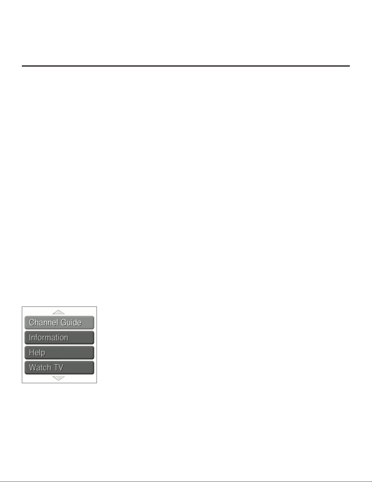
Pro:Centric Operation
Pro:Centric TV Interactive Menu Features
When running the Pro:Centric application, the interactive Pro:Centric TV enables guests to locate and
select television entertainment using an interactive channel guide, check the daily weather, and view hotel
and surrounding amenities via custom billboards and points-of-interest maps.
Pro:Centric application features include:
• Portal and information screens/pages (including a “Welcome” page) that include branding logos.
• An optional customized user interface (custom “skins”).
• Billboards and points-of-interest maps that can be customized to focus on hotel amenities, local attractions
and businesses, restaurants, news, events, etc.
• An optional Weather billboard that includes a local radar map, current conditions, and a four day forecast.
• An interactive channel guide that provides a channel list with channel icons. An electronic program
guide (EPG) is an optional feature that displays up to three days of programming information viewable
by channel and time.
• Video spooling that enables the hotel to deliver a video le to guest TVs for promotion and information
purposes.
The Pro:Centric server Admin Client web editor/content wizard is provided for customer conguration of
portal messages and billboards/maps.
Note: Customized content is typically dened by the service integrator and/or hotel administrators. LG
does not provide hotel-specic content.
Pro:Centric Interactive Menu Navigation
Use the Pro:Centric TV remote control to operate both interactive menus and regular TV features. Press
PORTAL on the remote to access the interactive menus.
Note: Interactive menu options may vary, depending on Pro:Centric features enabled for the site. The
following are default interactive menus.
Channel Guide
Shows available TV networks and logical channels. When available, EPG
data provides additional channel and program information.
Information
Typically displays information on hotel amenities, for example, restaurants,
in-room dining, business centers, facilities, etc., as well as information on
local weather and attractions.
Help
Provides help for navigating the interactive menus.
Watch TV
Removes the interactive menu from the screen and returns to the previously
tuned TV channel.
206-4213
9

Pro:Centric Operation (Cont.)
Pro:Centric Setup
Administration and management options for the Pro:Centric server are described in detail in the
Pro:Centric Server Admin Client User Guide. This document describes only those settings that must be
specied on the TVs.
On the TVs, the Data Channel must be set appropriately to enable Pro:Centric remote management/
administration facilities, while the Pro:Centric Application Mode must be set appropriately to enable the
Pro:Centric application.
• Remote management/administration (TV E-Z Installation): The Pro:Centric server Admin Client provides
remote management/administration facilities for downloading splash screens and software/firmware
updates as well as facilities for downloading the FTG Channel Map and FTG Installer Menu settings for
TVs that are in FTG Mode via CPU.
• Pro:Centric application: The application, which operates in conjunction with FTG and PPV Modes,
comprises the Pro:Centric interactive menus/features described on the previous page. Pro:Centric
application settings are managed via the Pro:Centric Admin Client.
The Data Channel and Pro:Centric Application Mode can be set using one of the following methods:
• When the TV is in a factory default state, the Automated Installation Routine Wizard provides Auto or
Manual options for conguring both the Data Channel and the Pro:Centric Application Mode.
The Automated Installation Routine Wizard also provides a USB Conguration option that enables you
to congure a TV for FTG Mode via CPU using an FTG Conguration (.tlx) le stored on a USB memory
device. The FTG Conguration le incorporates FTG Installer Menu settings, which includes Installer
Menu items 098 PRO:CENTRIC and 119 DATA CHANNEL.
Refer to “Automated Installation Routine Wizard” on pages 11 to 13 for further information on the
Automated Installation Routine Wizard options.
• If the TV is in Pass-through Mode, set Installer Menu items 098 PRO:CENTRIC and 119 DATA CHANNEL
to the appropriate values. Refer to “Installer Menu” information on pages 18 to 26 for further information.
Also, as necessary, refer to “Custom Master TV Setup” information on pages 14 to 17 and/or cloning
information on pages 28 to 36.
• If the TV is in FTG Mode (via CPU or EBL), use the appropriate software to update the Pro:Centric
and Data Channel Installer Menu items and then transfer the FTG Installer Menu settings to the TV in
accordance with the FTG Mode of conguration. Refer to FTG Mode information on pages 37 to 48 for
further information.
10
206-4213
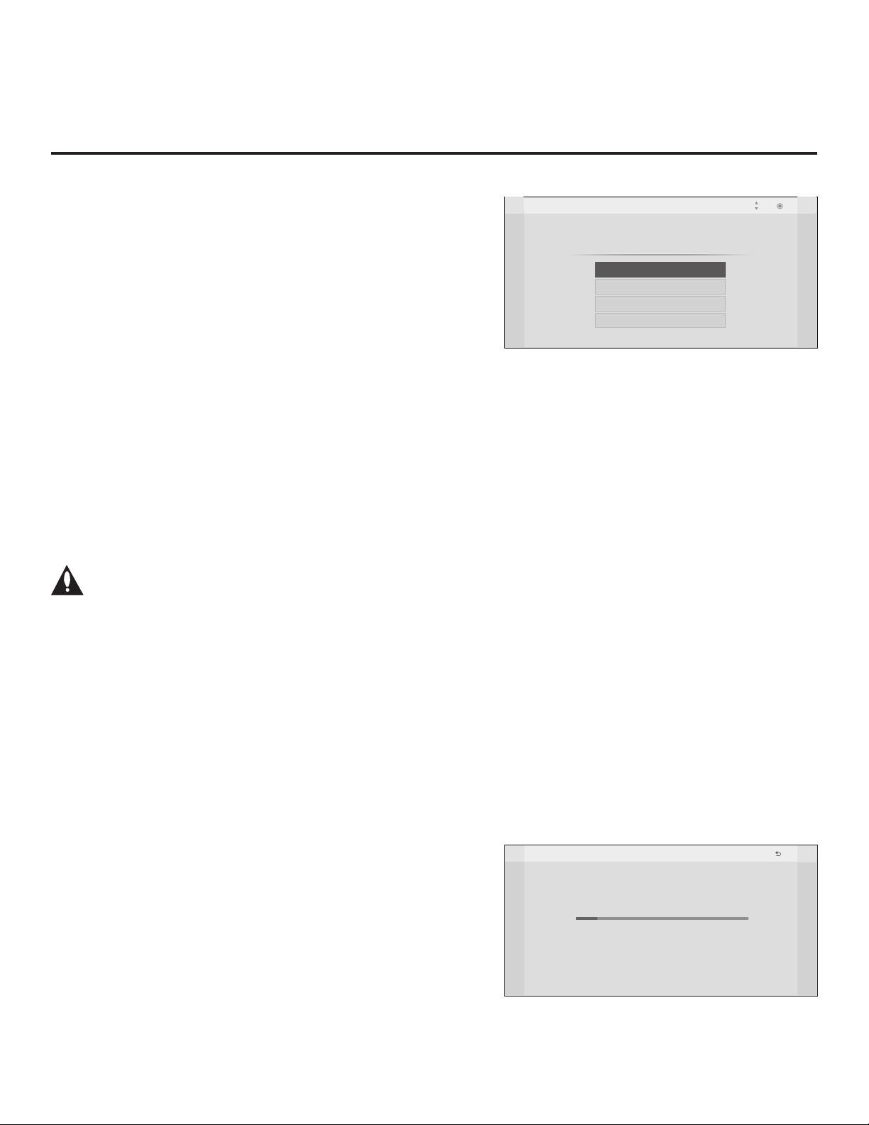
Automated Installation Routine Wizard
The Automated Installation Routine Wizard will appear on
the screen each time the TV is turned ON, until one of its
conguration methods has been completed or the wizard is
Welcome
Please select configuration method.
exited.
The wizard’s Welcome screen provides a selection of
conguration methods: Auto or Manual options for conguring
essential items for Pro:Centric operation and also an option
for using a USB memory device to congure the TV for FTG
Pro:Centric Auto
Pro:Centric Manual
USB Configuration
Exit
Mode via CPU. This section describes each of the Automated
Installation Routine Wizard options.
Note: If it has been completed or exited and therefore does not display, the Automated Installation
Routine Wizard can be re-activated; however, this requires that factory defaults be restored on the
TV(s). Refer to Reference section, “Restoring Factory Defaults on the TV(s),” for further information.
Note: If you plan to create a Master TV Setup using the procedure described on pages 14 to 17,
be sure to exit the Automated Installation Routine Wizard in order to avoid setting modes that may
restrict the custom setup procedure.
Note: If any of the conguration steps fails, you will see an “Incomplete” screen with an indication of
the failure. You will then have the opportunity to reinitiate the current conguration process, select
another conguration method (for example to select Pro:Centric Manual instead of Auto conguration),
or exit the Automated Installation Routine Wizard.
Caution: Do NOT unplug the TV power cord or remove the antenna cable during any of
the conguration processes, as doing so will interrupt the current step and may corrupt
the conguration data.
Move
OK
To exit the Automated Installation Routine Wizard, use the Up/Down arrow keys on the Installer
Remote to select/highlight Exit. Then, press OK.
Pro:Centric Auto Conguration
When selected, this option enables the TV to use a search algorithm to automatically determine the
type of Pro:Centric network, the (RF) Data Channel, and the Pro:Centric Application Mode. The TV
then looks for the Pro:Centric application and maintenance (E-Z Installation) les to download.
Note: If you intend to use the Pro:Centric server for remote management only of E-Z Installation
(splash screen, configuration, or firmware) data downloads, use the “Pro:Centric Manual” option
described on the following page.
Use the Up/Down arrow keys on the Installer Remote to select/
highlight Pro:Centric Auto from the Automated Installation
Routine Wizard Welcome screen. Then, press OK.
The Pro:Centric Auto Conguration will proceed with a series of
automated steps to congure the TV for Pro:Centric operation
and to download the Pro:Centric application and E-Z Installation
data. The Auto Conguration screen (see example at right)
shows overall progress, as well as the progress and/or values
for each of the individual installation steps. Note that some steps
may require up to 15 minutes.
When the Pro:Centric Auto Conguration is complete, the wizard
exits, and the TV will turn OFF.
Auto Configuration
Processing Pro:Centric Configuration.
Step 2 may take up to 15 min(s).
Please wait...
Step 1 Detecting the type of Pro:Centric network
Step 2 Locating the Pro:Centric Server
Step 3 Determining the Pro:Centric mode
Step 4 Downloading the application files
Step 5 Downloading the maintenance files
Step 6 Saving the Pro:Centric configuration
Warning - Do not remove AC power or the signal cables during these steps
Prev.
10%
:
RF
:
In Progress
:
:
:
:
206-4213
11
Automated Installation Routine Wizard (Cont.)
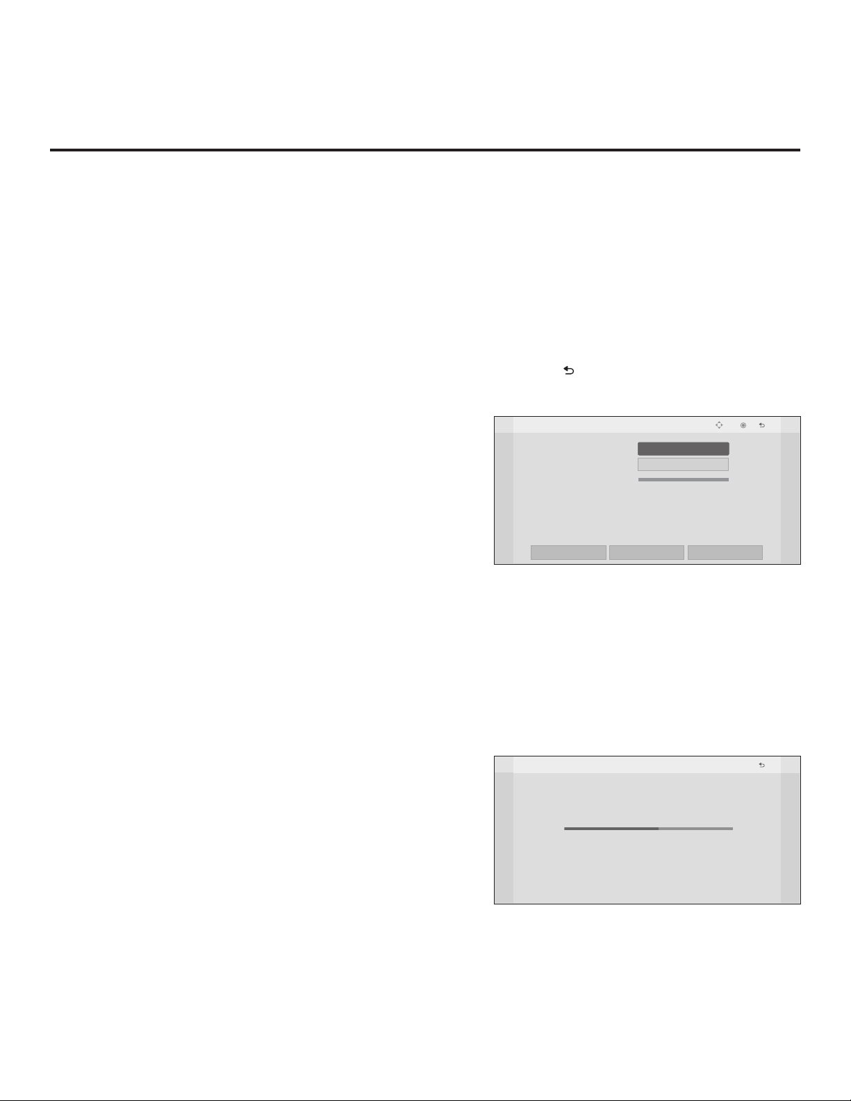
Pro:Centric Manual Conguration
If you already know the settings (i.e., Data Channel and Pro:Centric Application Mode) that need to
be congured in order for the TV to connect to the Pro:Centric server, you may streamline the setup
process by entering this data manually.
1. Use the Up/Down arrow keys on the Installer Remote to select/highlight Pro:Centric Manual
from the Automated Installation Routine Wizard Welcome screen. Then, press OK.
In the rst Manual Conguration Screen (see example below), you will be able to congure
the appropriate Pro:Centric settings. Use the Up/Down arrow keys on the Installer Remote to
navigate between elds.
Note: Select the “Back” button from the Manual Conguration screen or press the key on the
Installer Remote, if desired, to return to the Welcome screen.
2. In the Pro:Centric Mode eld, use the Left/Right arrow keys to
select the appropriate Pro:Centric Application Mode—GEM,
FLASH, or Conguration Only.
Note: For remote management only, select the Pro:Centric
Mode “Conguration Only” option to search for TV E-Z
Installation data downloads. Pro:Centric application data will
not be downloaded.
3. In the Channel Number eld, either key in or use the Left/
Right arrow keys to select the RF channel number for the
Data Channel of the Pro:Centric server. The Data Channel
can be set from 1 to 135.
4. Once all elds are completed as required, you may have two
options (see also note below):
• To save the data entered and exit the wizard, use the
arrow keys to select Save and Exit, and then press OK.
The Pro:Centric application and/or E-Z Installation data
will be downloaded to the TV at a later time. This option is
useful, in particular, if the Pro:Centric server has not yet
been congured.
• To initiate a real-time download of Pro:Centric application
and/or E-Z Installation data, use the arrow keys to select
Next, and then press OK.
The Pro:Centric Manual Conguration will proceed with
the remaining Pro:Centric application and/or E-Z Installation data download steps, as shown on the second Manual
Conguration screen (see example at right). When the
Pro:Centric Manual Conguration is complete, the wizard
exits, and the TV will turn OFF.
Note: The RF signal must be detected on the Data Channel
of the Pro:Centric server in order for you to select “Next” (you
will see a “Data Channel found” message below the signal
strength indicator).
Manual Configuration
Pro:Centric Mode
Channel Number
Signal Strength
BACK
Manual Configuration
Step 1 Detecting the type of Pro:Centric network
Step 2 Locating the Pro:Centric Server
Step 3 Determining the Pro:Centric mode
Step 4 Downloading the application files
Step 5 Downloading the maintenance files
Step 6 Saving the Pro:Centric configuration
Warning - Do not remove AC power or the signal cables during these steps
Save and Exit
Processing Pro:Centric Configuration.
Step 4 may take up to 5 min(s).
Please wait...
GEM
< >
1
:
:
DIGITAL 75
:
:
In Progress
:
:
0%
NEXT
50%
GEM
Move
Prev.
OK
Prev.
RF
12
206-4213

Automated Installation Routine Wizard (Cont.)
USB Conguration
This section describes how to congure a TV for FTG Mode via CPU operation using an FTG
Conguration (.tlx) le loaded on a USB memory device.
Note: Refer to the Free-To-Guest (FTG) File Manager User Guide and/or “Creating an FTG
Conguration File using the FTG File Manager” on pages 39 to 40 for information on creating an
FTG Conguration (.tlx) le.
Note: This procedure assumes that the FTG Conguration le contains an FTG Channel Map. If
not, any Installer Menu and/or TV setup menu settings contained in the le will be transferred to
the TV (as with typical cloning); however, the TV will remain in Pass-through Mode and will not be
congured for FTG Mode via CPU.
1. Plug the USB memory device that contains the FTG
Conguration (.tlx) le into the Target LT670H or LS675H
TV USB IN port.
2. Use the Up/Down arrow keys on the Installer Remote
to select/highlight USB Conguration from the Automated
Installation Routine Wizard Welcome screen. Then, press OK.
3. In the Accessing USB Storage Device window, use the Up/
Down arrow keys to select the FTG Conguration le you
wish to use to congure this TV, and then press OK.
The TV will show conguration progress in a new window.
Do NOT remove the USB device until conguration is
complete. When the conguration is complete, the TV will
briey display a “Complete” window and then exit the
Automated Installation Routine Wizard.
4. Remove the USB memory device, and verify that the FTG
Configuration is resident on the Target TV.
The Target TV CPU is now in FTG Mode.
Note: After the conguration process is complete, the TV tunes
according to the Start Channel setting in the Installer Menu. If
a Start Channel is specied, the TV will tune to that channel;
otherwise, the TV will tune to the lowest logical channel in the
FTG Channel Map.
Accessing USB Storage Device
Please select configuration file (*.tlx)
xxLT670H-UA00005.TLX
USB Configuration
Configuring TV
Please wait...
Warning - Do not remove the USB device during this process
Move
95%
Prev.
OK
206-4213
13

Custom Master TV Setup
This section describes how to create a customized Master TV Setup for cloning purposes when the TV is in
Pass-through Mode.
Note: Refer to FTG Mode information on pages 37 to 48 for details on entering FTG Mode and conguring/
editing the FTG Channel Map and FTG Installer Menu settings.
Note: Cloning requirements and procedures are described in detail on pages 28 to 36.
Before You Begin
• It is recommended that you disconnect all Aux
inputs if you intend to run Auto Tuning (Channel
Search). Under certain conditions, Auto Tuning
is disabled if there is an Aux input active.
• Determine which cloning tool—USB memory
device or clone programmer—is appropriate for
your application; several of the Master TV Setup
procedure steps are dependent on the cloning
tool to be used. See “Cloning Methods” at right
for further information.
• If you intend to use a USB memory device,
determine the type of le—either the new “.tlx”
le format or the legacy “.tll” le format—to use
for cloning purposes; several of the Master TV
Setup procedure steps are dependent on the
desired le type. See “Cloning Methods” at right
for further information.
• If the Automated Installation Routine Wizard
appears on the screen, exit the wizard before
beginning/continuing the Custom Master TV
Setup procedure.
Cloning Methods
See also “Clonable TV Setup Menu Features” list below.
Using a USB Memory Device / .tlx File
• The .tlx le format clones Installer Menu settings and all TV
sources’ (analog, digital, AV1, HDMI, etc.) clonable setup menu
settings.
• Not intended for cloning an auto-tuned/edited Channel Map, as
the channel lineup is converted to a logical FTG Channel Map
when saved (Learned) from a TV to a .tlx le. If the .tlx le with
the FTG Channel Map is then used for Teaching purposes, all
Target TVs will be congured for FTG Mode via CPU.
Using a USB Memory Device / .tll File
The .tll le format clones the contents of the commercial controller
(PTC) memory, including an auto-tuned/edited Channel Map,
Installer Menu settings, and one TV source’s (analog, digital, or
Aux) clonable setup menu settings.
Using a Clone Programmer (TLL-1100A or LT2002)
Both the TLL-1100A and LT2002 clone the contents of the
commercial controller (PTC) memory, including an auto-tuned/
edited Channel Map, Installer Menu settings, and one TV source’s
(analog or Aux) clonable setup menu settings.
Clonable TV Setup Menu Features
Channel
Auto Tuning (Channel Lineup)
Manual Tuning
Channel Edit
Channel Label
Picture
Picture Mode
Note: Some menu options vary between analog and digital channels and Aux inputs.
14
Audio
Auto Volume
Clear Voice
Sound Mode
Balance
TV Speaker
Time
Auto Clock
Auto Off (Sleep Timer)
Option
Menu Language
Audio Language
Caption
Lock
Movie Rating
TV Rating – Children
TV Rating – General
206-4213

Custom Master TV Setup (Cont.)
Custom Master TV Setup Procedure
1. Turn ON the TV.
If the Automated Installation Routine Wizard appears on the screen when you turn ON the
TV, use the Up/Down arrow keys on the Installer Remote to select Exit from the Welcome
screen, and press OK to exit the wizard.
2. Set Installer Menu items.
This step provides specic instruction only on the Installer Menu items
that should be set on a Master TV. Refer to pages 18 to 26 for detailed
information on all Installer Menu items.
a) Use the Installer Remote to access the PTC Installer Menu (see
“Accessing the Installer Menu” on page 18 for further information).
The next step depends on whether the Automated Installation
Routine Wizard appeared when you turned ON the TV:
• If the wizard did appear, the TV is in a factory default state, and
you can proceed to set Installer Menu items. Go to step (c).
• If the wizard did not appear, go to step (b).
b) Set Installer Menu item 117 FACT DEFAULT to 001 and press
OK on the Installer Remote.
This clears all Installer Menu custom settings, channel lineup, etc.
and restores the factory default settings. The value will change
back to 0 after the PTC has been restored to factory default
condition. This step ensures that the TV Channel Memory will be
the active channel lineup.
c) Set Installer Menu item 003 BAND/AFC, as appropriate.
• Broadcast: Set to 000. • HRC: Set to 002.
• CATV: Set to 001 (default). • IRC: Set to 003.
d) Set any other Installer Menu items that affect your TV programming
network to the required conguration. For example, enable/disable
Aux inputs, set a Start Channel, etc.
e) After you have adjusted all Installer Menu item settings as required,
press OK once on the Installer Remote to save your changes; then,
press OK again to exit the menu.
Note: If you performed step (b) above to restore factory defaults,
the Automated Installation Routine Wizard will re-activate as soon
as you exit the Installer Menu. Exit the wizard (see step 1), and
then continue with step 3.
3. Set up TV features.
On-screen setup menus control the features of the TV. Press MENU
SETTINGS on the Installer Remote to access the TV setup menus,
and then set Channel, Picture, Audio, Lock, Time, etc. options to the
desired configurations. See “Clonable TV Setup Menu Features” list on
previous page and also notes on the following page.
Note: The Installer Menu header will vary
depending on the TV you are setting up.
PICTURE
Use the TV setup menus to set the TV
xxLT670H PTC INSTALLER MENU
000 INSTALLER SEQ 000
UPN 000-000-000-000 ASIC D279
PTC V1.00.009 CPU V3.17.00
117 FACT DEFAULT 000
003 BAND/AFC 001
Adjust the values for these
Installer Menu items, as required.
LOCK
features to the desired configuration
CPU-CTV
Typical Installer Menu
AUDIO
OPTION
for the end user.
CHANNEL
INPUT
(Continued on next page)
TIME
MY MEDIA
206-4213
15

Custom Master TV Setup (Cont.)
(Continued from previous page)
Note: If you intend to clone the PTC, remember that only one TV source’s clonable setup
menu settings will be cloned. Thus, for a clone programmer, the TV setup menu settings
should be applicable to either an analog channel or Aux input, while for a USB device / .tll file,
the TV setup menu settings should be applicable to the analog or digital channel or Aux input
to which the Target TV will be set during the Teaching process.
Note: If desired and if appropriate depending on the cloning method to be used (see “Cloning
Methods” on page 14), you can run Auto Tuning (see step 4) prior to completing this step.
4. (Optional) Run Auto Tuning.
Note: If you intend to use a USB memory device / .tlx file
for cloning purposes, DO NOT run Auto Tuning. If you
Teach a .tlx file with an auto-tuned/edited Channel Map to
a Target TV, this will put the Target TV in FTG Mode via
CPU. Proceed to step 7 to verify the TV setup. (Steps 5
and 6 are not applicable for .tlx files.)
If you run Auto Tuning with the intention to clone the resulting
Channel Map, you must use a USB memory device / .tll file or a
clone programmer for this cloning purpose.
a) To search for all available analog and digital channels, go to the
Channel Menu, select the Auto Tuning option, and follow the
on-screen instructions.
b) Use the Channel Edit option in the Channel Menu to edit the
channel lineup, as necessary, to include only free to guest (nonencrypted) channels.
• Add/delete channels per your system requirements.
• Use the Channel Label option in the Channel Menu to select
the appropriate trademark/icon for each channel’s Channel-Time
on-screen display. Icons are available for familiar channels,
such as ABC, CBS, NBC, etc. Identiable labels (icons) should
enable the end user to readily know what common networks are
available.
Note: If you intend to clone the PTC and Installer Menu item 103
ATSC TUNE MODE is set for Physical Channel tuning (default
and recommended setting), channels with minor channel numbers
higher than 255 will not transfer correctly in step 5. If item 103 is
set for Virtual Channel tuning and either the major or minor channel
numbers are higher than 255, the channel(s) will not transfer
correctly in step 5.
Note: If you intend to clone the PTC, you can add the channel
icons in this step or as described in step 6. Also in step 6, you can
add custom text labels for channels without icons.
(Optional) Use Channel Menu options
to run Auto Tuning, edit channels, and
CHANNEL
• Auto Tuning
• Manual Tuning
• Channel Edit
• Channel Label
select channel icons.
Move
OK
16
(Continued on next page)
206-4213
Custom Master TV Setup (Cont.)
(Continued from previous page)
5. Transfer the TV setup menu settings to the commercial controller (PTC):
2-5-5 + MENU Mode
Note: This step is essential for successful cloning using a USB memory device /
.tll file or a clone programmer. Without this step, the PTC will not contain any of
the TV setup menu settings.
Note: The maximum number of channels (analog, digital, and Aux inputs) that can
be transferred to the PTC is 141. An attempt to transfer more than 141 channels of
any combination will result in a Channel Map of exactly 141 channels; any extra
channels will not be available in the PTC Channel Map. For example, if you enabled
three Aux inputs in the Installer Menu and Auto Tuning found 141 channels, you
must edit the Channel Map to decrease the number of analog/digital channels to (at
most) 138.
a) After the TV channel lineup has been edited and channel label icons added, tune to the
channel (source) for which you wish to transfer TV setup menu settings.
Note: If you intend to use a clone programmer for cloning purposes, this must be either
an analog channel or Aux input.
b) Access the Installer Menu, and press 2-5-5 + MENU SETTINGS on the Installer
Remote to initiate the transfer of the Master TV Setup to the PTC. The TV exits the
Installer Menu and then tunes through the channels in the channel lineup during the
transfer. When the transfer is complete, the TV tunes back to the channel that was
tuned before the transfer began.
6. (Optional) Add Custom Channel and Aux Input Labels:
2-5-4 + MENU Mode
Note: 2-5-4 + MENU Mode enables you to add/edit channel icons and
custom text labels in the PTC once the Master TV Setup has been
transferred as described in the previous step.
Access the Installer Menu, and press 2-5-4 + MENU SETTINGS on the
Installer Remote. Add/edit custom text labels and/or change icons for
the Channel-Time on-screen displays (see 2-5-4 + MENU procedural
information on page 27). Note that broadcast digital channels often
already have a broadcaster generated label. When you are finished,
press MENU SETTINGS to exit 2-5-4 + MENU Mode.
7. Verify the TV setup.
As applicable, verify that the channel lineup, channel icons, and custom
text labels are correct. Also, make sure the TV features are set per your
requirements.
8. (Recommended) Lock the channel lineup.
Access the Installer Menu. Set item 028 CH. OVERIDE to 000 and
press OK to lock the channel lineup and restrict access to the TV
setup menus. Press OK again to save your changes and exit the
Installer Menu.*
The Master TV Setup is now ready to be copied to the predetermined
cloning tool—a USB memory device (.tlx or .tll le) or a clone programmer.
See cloning procedures in this document.
DIGITAL 19-3
STEREO SAP
MONO
WXYZ
Custom text label “WXYZ” created
in 2-5-4 + MENU Mode.
028 CH. OVERIDE 000
After verifying the TV Setup, set Installer
Menu item 028 CH. OVERIDE to 000.*
* This step prevents end users from
accessing channel settings (i.e., the
Channel Menu will be inaccessible/
grayed out).
206-4213
17

Installer Menu
Use the Installer Menu to set up, change, or view operational settings. Refer to the table on pages
20 and 21 for brief descriptions of Installer Menu items. More detailed descriptions follow the table
listing.
Accessing the Installer Menu
1. Turn ON the TV.
If the Automated Installation Routine Wizard appears on the
screen when you turn ON the TV, use the Up/Down arrow keys
on the Installer Remote to select Exit from the Welcome screen,
and press OK to exit the wizard.
2. Using an Installer Remote, press MENU SETTINGS repeatedly
until the on-screen display of the TV setup menus (if the TV is
in Pass-through Mode) or the Function Menu (if the TV is not in
Pass-through Mode) no longer toggles, and then press the
Installer Menu entry sequence (e.g., 9-8-7-6) + OK to access the
Installer Menu.
Note: The default Installer Menu entry sequence is “9876”;
however, if Installer Menu item 000 INSTALLER SEQUENCE
has been modied, the entry sequence may be one of three
additional options. See Installer Menu detailed descriptions for
further information.
The Installer Menu opens with item 000 INSTALLER SEQ 000.
Note: If the password (entry sequence) is not entered or registered correctly, you will see the
message “ENTER PASSWORD 0000” at the top of the screen instead of the Installer Menu
header. Once you re-enter the correct password (e.g., press 9-8-7-6 + OK), the Installer Menu will
display.
Note: If the TV is not in Pass-through Mode, the Installer Menu is accessible as read-only.
xxLT670H PTC INSTALLER MENU
000 INSTALLER SEQ 000
UPN 000-000-000-000 ASIC D279
PTC V1.00.009 CPU V3.17.00
Typical Installer Menu
CPU-CTV
As part of the Installer Menu header, two 3-character acronyms are displayed to indicate the
TV’s current conguration mode. The table below lists all possible mode identiers for these TV
models.
Acronym Description
CPU-CTV Pass-through Mode with Channel Map in CPU
CPU-FTG FTG Mode via CPU
EBL-FTG FTG Mode via EBL
EBL-LNT LodgeNet PPV Mode
MPI-EXT External MPI Control
PTC-CTV Pass-through Mode with Channel Map in PTC
18
206-4213

Installer Menu (Cont.)
Using the Installer Menu
Refer to the table starting on the next page for an overview of the available Installer Menu items,
including their item numbers, functions, value ranges, and default values.
Installer Menu items not relevant to these TV models are not present in the Installer Menu; therefore,
some numbers are missing. For example, item 006 will not appear. In addition, items that are
dependent on other Installer Menu item settings will not be initially accessible. For example, item 046
STRT AUX SRCE will not display in the Installer Menu unless item 004 STRT CHANNEL is set to 0.
Navigation within the Installer Menu
Use the Up/Down arrow keys on the Installer Remote to sequence through the available menu
items, or access an item directly by keying in the item number and then pressing MENU SETTINGS.
For example, to access the SLEEP TIMER option, which is item 015, press 0-1-5 + MENU.
Changing Installer Menu Settings
To change an Installer Menu item value, use the Left/Right arrow keys on the Installer Remote, or
enter a valid value directly. To save the new setting, press OK, or use the Up/Down arrow keys to
navigate to a new Installer Menu item if you have additional items to edit. Note that invalid values will
not be saved.
Exiting the Installer Menu and Activating Updates
After you have adjusted all required Installer Menu item settings, press OK once on the Installer
Remote to save your changes; then, press OK again to exit the Installer Menu. Any changes you
make will be stored in non-volatile memory.
Note: Each time you exit the Installer Menu in Pass-through Mode, all V-Chip (Parental Control)
settings in the TV are reset to their default values; that is, the Lock System, if previously enabled
from the Lock setup menu, will now be disabled, and the individual Parental Control settings will be
restored to default values.
206-4213
19

Installer Menu (Cont.)
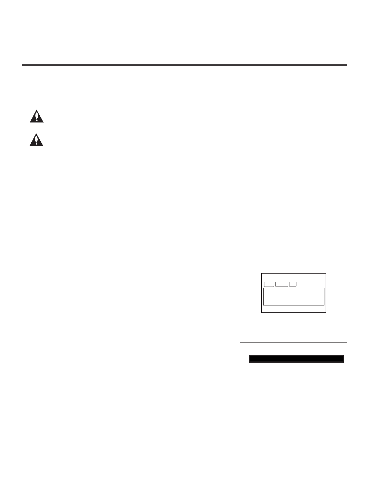
Installer Menu Items 000 through 075
Menu
Item
* Value 2 applicable for LS675H TVs only.
Function Value Range Default Value Brief Description of Function and Comments
000 INSTALLER SEQ 0 ~ 3 0 Leave default set to 0.
001 POWER MANAGE 0 ~ 7 0 Sets number of hours of no activity before automatic shutoff.
002 AC ON 0 / 1 0 Set to 1 to enable Auto Turn ON when AC power is applied.
003 BAND/AFC 0 ~ 3 1 Selects Tuning Band: 0=Broadcast, 1=CATV, 2=HRC, 3=IRC
004 STRT CHANNEL 0 ~ 127, 255 255
005 CHAN LOCK 0 / 1 0 If set to 1, cannot tune from current channel.
007 STRT VOLUME 0 ~ 63, 255 255
008 MIN VOLUME 0 ~ 63 0 Sets minimum allowable volume setting.
009 MAX VOLUME 0 ~ 63 63 Sets maximum allowable volume setting.
010 MUTE DISABLE 0 / 1 0 Set to 1 to disable Mute Function.
011 KEY DEFEAT 0 / 1 0 Set to 1 to disable menu navigation keys on display panel.
015 SLEEP TIMER 0 / 1 1 Set to 1 to enable Sleep Timer.
016 EN TIMER 0 / 1 0 Set to 1 to enable On/Off Timers.
017 ALARM 0 / 1 1 Set to 1 to enable Alarm.
020 FEATURE LEVEL 0, 16 ~ 24 0 Determines an additional IR code scheme to which the TV will respond.
021 V-CHIP 0 / 1 1 Set to 1 to enable V-Chip (Parental Control) functions.
022 MAX BLK HRS 0 ~ 99 12 Sets number of V-Chip blocking hours.
023 CAPTION LOCK 0 / 1 0 Set to 1 to retain caption setting set before TV turned OFF.
028 CH. OVERIDE 0 / 1 1 If set to 0, limits direct access to favorite channels.
029 OLD OCV 0 / 1 0 Set to 1 to change MPI operation to OCV.
030 ACK MASK 0 / 1 0 If set to 1, enables ACK feature of MPI.
031 POLL RATE 20 ~ 169 94 Selects poll rate for MPI.
032 TIMING PULSE 186 ~ 227 207 Sets baud rate for MPI.
035 HDMI1 ENABLE 0, 1, 2 *
039 REAR AUX EN. 0 / 1 1 Set to 1 to enable display panel Video 1 input jack.
041 SIMPLINK EN 0 ~ 3 0 Determines the status of the SIMPLINK feature. (See detailed descriptions.)
046 STRT AUX SRCE 1, 3 ~ 5, 7, 255 7 Sets the starting Aux source (if item 004 STRT CHANNEL is set to 0).
047 AUX STATUS 0 / 1 0
053 DIS. CH-TIME 0 / 1 0 Set to 1 to disable Channel-Time display.
069 EN. CH-T COL. 0 / 1 1 Set to 1 to enable custom color for the Channel-Time display.
070 FOR. CH-TIME 0 ~ 7 2 Chooses custom foreground color for the Channel-Time display.
071 BCK. CH-TIME 0 ~ 7 2 Chooses custom background color for the Channel-Time display.
073 CH NOT AVBLE 0 / 1 0
075 REVERT CH 0 / 1 0 If set to 1 and loss of MPI communication occurs, TV tunes to Start Channel.
1 (LT670H)
2 (LS675H)
Channel tuned when TV is turned ON. (Set to 255 to tune to channel
tuned before TV turned OFF.)
Volume level when TV is turned ON. (Set to 255 to use volume level
before TV turned OFF.)
Set to 0 to disable HDMI 1. Set to 1 or 2, as applicable, to enable HDMI 1
(See detailed descriptions.)
Set to 1 for MPI Aux source to be reported as a channel number instead of
Channel 0.
If set to 1 and item 028 CH. OVERIDE is set to 0, “NOT AVAILABLE” message
is displayed if user direct tunes a channel that is not in the favorite channel list.
20
206-4213

Installer Menu Items 078 through 122
Installer Menu (Cont.)
Menu
Item
* Value 2 applicable for LS675H TVs only. ** Value 9 applicable for LT670H TVs only.
Function Value Range Default Value Brief Description of Function and Comments
078 UPN MSB 0 ~ 255 0 User programmable number, most significant byte.
079 UPN MSB-1 0 ~ 255 0 User programmable number, most significant byte - 1.
080 UPN MSB-2 0 ~ 255 0 User programmable number, most significant byte - 2.
081 UPN LSB 0 ~ 255 0 User programmable number, least significant byte.
082 CHKSM ERROR 0 / 1 1 Enforces rigid MPI checksum.
083 HANDSHK TIME 0 ~ 5 5
084 PERMANENT BLK 0 / 1 0 Removes block hours setting for Parental Control and makes block permanent.
087 REAR RGB EN.
088 EN NOISE MUTE 0 / 1 1 If set to 1, audio is muted if no signal is present.
090 KEY LOCK 0 / 1 0 If set to 1, keyboard is locked out, IR is still functional.
091 HDMI2 ENABLE 0, 1, 2 *
092 HDMI3 ENABLE 0, 1, 2 *
093 RJP AVAILABLE 0, 1, 2, 5, 6 0
094 SAP MENU EN 0 / 1 1
096 DEF. ASP. RATIO 0 ~ 4 2 Sets default aspect ratio at power up. See detailed descriptions and item 106.
098 PRO:CENTRIC
099 BACK LIGHTING
102 ATSC BAND 0 ~ 4 4 Selects ATSC band.
103 ATSC TUNE MODE 0 / 1 1 Set to 1 (default) for Physical Channel scan. Set to 0 for Virtual Channel scan.
104 START MINOR CH 0 ~ 255 0 Selects Minor Start Channel. Set to 0 for NTSC.
106 ASP RATIO LOCK 0 / 1 0
116 VIDEO MUTE EN 0 / 1 0 Set to 0 for Normal. Set to 1 for Blank.
117 FACT DEFAULT 0 / 1 0 Set to 0 for Normal. Set to 1 to load presets for all Installer Menu settings.
118 POWER SAVINGS 1, 3, 7, 9 ** 3
119 DATA CHANNEL 0 ~ 135 0
121 P:C RF WAKE HR 0 ~ 23, 128 128
122 P:C RF WAKE MN 0 ~ 59 0
0 / 1 / 17
0 ~ 2
1 ~ 100,
101 ~ 200, 255
1
1 (LT670H)
2 (LS675H)
1 (LT670H)
2 (LS675H)
0
100
Relaxes MPI timing to be compatible with PC-based Windows-
controlled systems.
Dependent on item 093 RJP AVAILABLE setting. Set to 0 to disable RGB input.
Set to 1 to enable RGB input. Set to 17 for Auto Configure.
Set to 0 to disable HDMI 2. Set to 1 or 2, as applicable, to enable HDMI 2.
(See detailed descriptions.)
Set to 0 to disable HDMI 3. Set to 1 or 2, as applicable, to enable HDMI 3.
(See detailed descriptions.)
Set to 0 to disable. Set to 1, 2, 5, or 6 for HDMI or DVI Mode. (See
detailed descriptions.)
Set to 0 to disable feature on Function Menu. Set to 1 to enable feature on
Function Menu.
Set to 0 to disable Pro:Centric operation. Set to 1 for Flash Mode. Set to 2 for
GEM (Java Application) Mode.
Sets the level of the TV picture back lighting. (See detailed descriptions.)
To retain set aspect ratio on power cycle, set to 1. Set to 0 for default ratio on
power cycle.
Determines the powered status of the embedded b-LAN module and the
GAME CONTROL/MPI port. (See detailed descriptions.)
Set to 0 to disable. Set to the RF channel number of the Data Channel for
Pro:Centric or TV E-Z Installation data. (See detailed descriptions.)
Sets the hour for Wake On RF. The value “128” is displayed as “OFF.” Directly
entering 128 turns the Wake On RF feature OFF.
Sets the minute for Wake On RF.
206-4213
Caution: Installer Menu settings may affect options available
from the TV setup menus or the Function Menu.
21
 Loading...