

LG 26LDA Users manual

Test Report No.: GETEC-E3-05-025
FCC Class B Certification
APPENDIX H
: USER’S MANUAL
EUT Type: 26” LCD TV/Monitor
FCC ID: BEJ26LDA
LCD TV
Please read this manual carefully before operating your set.
Retain it for future reference.
Record model number and serial number of the set.
See the label attached on the back cover and quote
this information to your dealer
when you require service.
P/NO : 3828TUL309D (0503-REV00)
Printed in Korea
OWNER’S MANUAL
MODELS: 26LX1D 32LX1D
26LX2D 32LX2D
32LP1D 37LP1D 42LP1D
Internet Home Page : http://www.lge.com
http://www.lg.ca
TM
Warning
WARNING:
TO REDUCE THE RISK OF ELECTRIC SHOCK DO NOT REMOVE COVER (OR BACK). NO USER
SERVICEABLE PARTS INSIDE. REFER TO QUALIFIED SERVICE PERSONNEL.
The lightning flash with arrowhead symbol, within an equilateral triangle, is intended to alert the user to
the presence of uninsulated “dangerous voltage” within the product’s enclosure that may be of sufficient magnitude to constitute a risk of electric shock to persons.
The exclamation point within an equilateral triangle is intended to alert the user to the presence of
important operating and maintenance (servicing) instructions in the literature accompanying the appliance.
NOTE TO CABLE/TV INSTALLER:
This reminder is provided to call the CATV system installer’s attention to Article 820-40 of the National Electric
Code (U.S.A.). The code provides guidelines for proper grounding and, in particular, specifies that the cable
ground shall be connected to the grounding system of the building, as close to the point of the cable entry as practical.
REGULATORY INFORMATION
This equipment has been tested and found to comply with the limits for a Class B digital device, pursuant to Part
15 of the FCC Rules. These limits are designed to provide reasonable protection against harmful interference in
a residential installation. This equipment generates, uses and can radiate radio frequency energy and, if not
installed and used in accordance with the instructions, may cause harmful interference to radio communications.
However, there is no guarantee that interference will not occur in a particular installation. If this equipment does
cause harmful interference to radio or television reception, which can be determined by turning the equipment off
and on, the user is encouraged to try to correct the interference by one or more of the following measures:
- Reorient or relocate the receiving antenna.
- Increase the separation between the equipment and receiver.
- Connect the equipment into an outlet on a circuit different from that to which the receiver is connected.
- Consult the dealer or an experienced radio/TV technician for help.
Any changes or modifications not expressly approved by the party responsible for compliance could void the
user’s authority to operate the equipment.
CAUTION:
Do not attempt to modify this product in any way without written authorization from LG Electronics Corporation.
Unauthorized modification could void the user’s authority to operate this product.
U.S.A. only -----------------------------------------------
COMPLIANCE:
The responsible party for this product’s compliance is:
LG Electronics U.S.A., Inc.
1000 Sylvan Avenue, Englewood Cliffs, NJ 07632
Phone: 1-201-816-2000
http://www.lgusa.com
---------------------------------------------------------------
CAUTION
RISK OF ELECTRIC SHOCK
DO NOT OPEN
W
W
arning
arning
Introduction
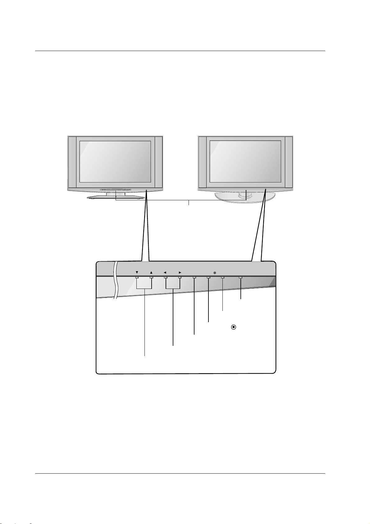
Controls
Controls
(Model Name: 26/32LX1D, 26/32LX2D)
(Model Name: 26/32LX1D, 26/32LX2D)
- This is a simplified representation of front panel.
- Here shown may be somewhat different from your TV.
CH
VOL MENUMENU
TV/ VIDEO/ TV GUIDE
ON/OFFON/OFF
VOLUME (F,G) Buttons
Remote Control Sensor
/Power Standby Indicator
Illuminates red when the TV is in standby
mode.
Blinks green while the TV switched on
and illuminates green when the TV is
switched on.
CHANNEL (E, D) Buttons
MENU Button
ON/OFF Button
TV GUIDE Button
TV/VIDEO
/ Button
Introduction
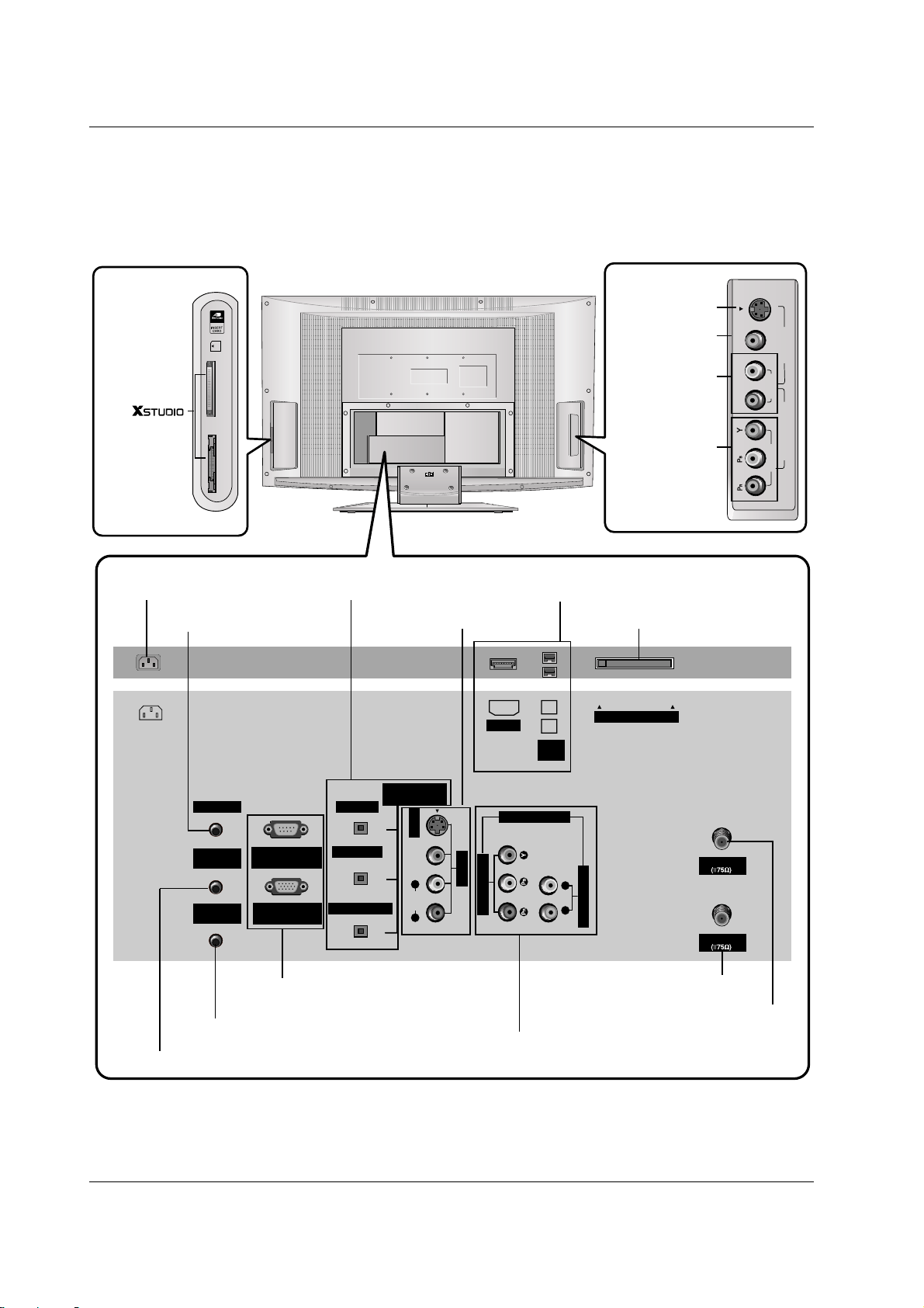
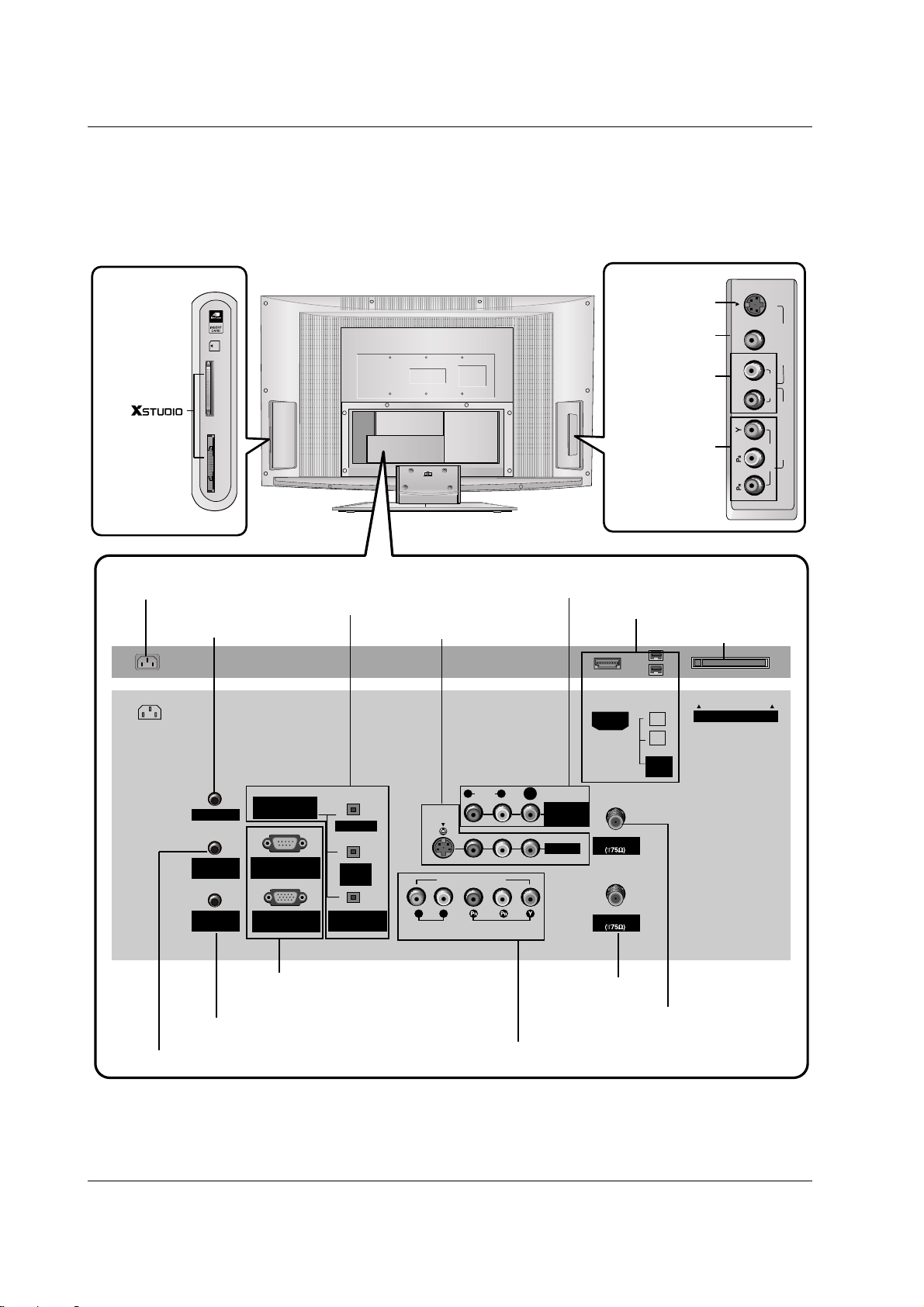
Connection Options (Model Name: 26LX1D/2D)
Connection Options (Model Name: 26LX1D/2D)
* The HDMI port can receive video via High-Definition Multimedia Interface (HDMI) or the Digital Visual Interface
(DVI). Note: An adapter or special cable is required to plug DVI into an HDMI port (available at home theater or
computer stores).
R
(MONO)
L VIDEO
S-VIDEO
VIDEO
AUDIO
COMPONENT 2
VIDEO 2
Slot 2
Slot 1
MS/MS-pro/xD/MMC/SMC/SD
CF/MD/Magicstor
ANTENNA
G-LINK
DIGITAL AUDIO
(OPTICAL)
OUTPUT
VIDEO1
RGB INPUT
(PC/DTV INPUT)
RS-232C INPUT
(CONTROL/SERVICE)
AUDIO INPUT
VIDEO INPUT
RL
PC AUDIO
INPUT
REMOTE
CONTROL
S-VIDEO
CableCARD
IEEE
1394
CABLE
AC IN
AUDIO VIDEO
(MONO)
RL
HDMI
DVI INPUT
COMPONENT1 INPUT
COMPONENT1
COMPONENT2
(VIDEO Input)
AUDIO Input
VIDEO2
S-VIDEO
Memory
Card Slot
(Formmmm
mode)
DIGITAL AUDIO OUTPUT / DVI INPUT
/ COMPONENT1 INPUT
AUDIO/VIDEO INPUT1
COMPONENT1 (VIDEO / AUDIO INPUT)
HDMI / IEEE1394 Port
CableCARDTMSlot
ANTENNA Input
CABLE Input
AC IN
G-LINKTMPort
PC AUDIO INPUT
RS-232C INPUT (CONTROL/SERVICE) /
RGB INPUT (PC/DTV INPUT)
REMOTE CONTROL Port
- Here shown may be somewhat different from your TV.
Connection Options (Model Name: 32LX1D/2D)
Connection Options (Model Name: 32LX1D/2D)
R
(MONO)
L VIDEO
S-VIDEO
VIDEO
AUDIO
COMPONENT 2
VIDEO 2
Slot 2
Slot 1
MS/MS-pro/xD/MMC/SMC/SD
CF/MD/Magicstor
ANTENNA
G-LINK
DIGITAL AUDIO
(OPTICAL)
DVI
INPUT
COMPONENT1
INPUT
OUTPUT
VIDEO1
RGB INPUT
(PC/DTV INPUT)
RS-232C INPUT
(CONTROL/SERVICE)
AUDIO INPUT
AUDIO
(MONO)
VIDEO INPUT
COMPONENT1
RL
RL
PC AUDIO
INPUT
REMOTE
CONTROL
S-VIDEO
CableCARD
IEEE
1394
CABLE
AC IN
MONITOR
OUT
VIDEO
HDMI
COMPONENT2
(VIDEO Input)
AUDIO Input
VIDEO2
S-VIDEO
Memory
Card Slot
(Formmmm
mode)
* The HDMI port can receive video via High-Definition Multimedia Interface (HDMI) or the Digital Visual Interface
(DVI). Note: An adapter or special cable is required to plug DVI into an HDMI port (available at home theater or
computer stores).
DIGITAL AUDIO OUTPUT
/ DVI INPUT
/ COMPONENT1 INPUT
AUDIO/VIDEO INPUT1
COMPONENT1 (VIDEO / AUDIO INPUT)
MONITOR OUT
HDMI / IEEE1394 Port
CableCARDTMSlot
ANTENNA Input
CABLE Input
AC IN
G-LINKTMPort
PC AUDIO INPUT
RS-232C INPUT (CONTROL/SERVICE) /
RGB INPUT (PC/DTV INPUT)
REMOTE CONTROL Port
- Here shown may be somewhat different from your TV.
21
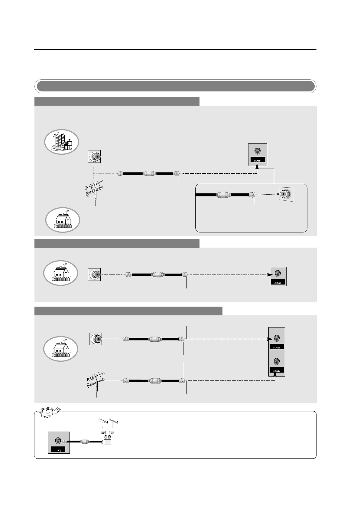
Installation
Antenna or Cable Connection
Multi-family Dwellings/Apartments
(Connect to wall antenna socket)
Single-family Dwellings /Houses
(Connect to wall jack for outdoor antenna)
Outdoor Antenna
Wall Antenna Socket
VHF Antenna
UHF Antenna
RF Coaxial Wire (75 ohm)
Turn clockwise to tighten.
ANTENNA
Bronze Wire
Be careful not to bend the bronze wire when
connecting the antenna.
Analog and Digital TV signals provided on antenna
- Antenna or Cable Service without a Cable Box Connection.
- For optimum picture quality, adjust antenna direction if needed.
Cable TV Wall Jack
RF Coaxial Wire (75 ohm)
Turn clockwise to tighten.
CABLE
Analog and Digital TV signals provided on cable
Analog and Digital TV signals provided on cable and antenna
Cable TV Wall Jack
RF Coaxial Wire (75 ohm)
Bronze Wire
Bronze Wire
Turn clockwise to tighten.
Antenna
RF Coaxial Wire (75 ohm)
• In a poor signal area to improve picture quality, purchase and install a signal amplifier.
• If the antenna needs to be split for two TV’s, install a “2-Way Signal Splitter”
in the connections.
• If the antenna is not installed properly, contact your dealer for assistance.
ANTENNA
External Equipment Connections
External Equipment Connections
signal
amplifier
CABLE
ANTENNA
 Loading...