

LG 23ET83V Service Manual
Internal Use Only
North/Latin America http://aic.lgservice.com
Europe/Africa http://eic.lgservice.com
Asia/Oceania http://biz.lgservice.com
LED TOUCH MONITOR
SERVICE MANUAL
CHASSIS : LM13J
MODEL : 23ET83V 23ET83V-WB
CAUTION
BEFORE SERVICING THE CHASSIS,
READ THE SAFETY PRECAUTIONS IN THIS MANUAL.
Printed in KoreaP/NO : MFL63731118 (1301-REV00)

CONTENTS
CONTENTS .............................................................................................. 2
SAFETY PRECAUTIONS ........................................................................ 3
SPECIFICATION ....................................................................................... 4
ADJUSTMENT INSTRUCTION ................................................................ 5
BLOCK DIAGRAM .................................................................................... 9
EXPLODED VIEW .................................................................................. 10
SCHEMATIC CIRCUIT DIAGRAM ..............................................................
Only for training and service purposes
- 2 -
LGE Internal Use OnlyCopyright © LG Electronics. Inc. All rights reserved.
To Instrument's
exposed
METALLIC PARTS
Good Earth Ground
such as WATER PIPE,
CONDUIT etc.
AC Volt-meter
SAFETY PRECAUTIONS
IMPORTANT SAFETY NOTICE
Many electrical and mechanical parts in this chassis have special safety-related characteristics. These parts are identified by in the
Schematic Diagram and Exploded View.
It is essential that these special safety parts should be replaced with the same components as recommended in this manual to prevent
Shock, Fire, or other Hazards.
Do not modify the original design without permission of manufacturer.
General Guidance
An isolation Transformer should always be used during the
servicing of a receiver whose chassis is not isolated from the AC
power line. Use a transformer of adequate power rating as this
protects the technician from accidents resulting in personal injury
from electrical shocks.
It will also protect the receiver and it's components from being
damaged by accidental sh orts of the cir cui try that may be
inadvertently introduced during the service operation.
If any fuse (or Fusible Resistor) in this TV receiver is blown,
replace it with the specified.
When replacing a high wattage resistor (Oxide Metal Film Resistor,
over 1 W), keep the resistor 10 mm away from PCB.
Keep wires away from high voltage or high temperature parts.
Before returning the receiver to the customer,
always perform an AC leakage current check on the exposed
metallic parts of the cabinet, such as antennas, terminals, etc., to
be sure the set is safe to operate without damage of electrical
shock.
Leakage Current Cold Check(Antenna Cold Check)
With the instrument AC plug removed from AC source, connect an
electrical jumper across the two AC plug prongs. Place the AC
switch in the on position, connect one lead of ohm-meter to the AC
plug prongs tied together and touch other ohm-meter lead in turn to
each exposed metallic parts such as antenna terminals, phone
jacks, etc.
If the exposed metallic part has a return path to the chassis, the
measured resistance should be between 1 M
When the exposed metal has no return path to the chassis the
reading must be infinite.
An other abnormality exists that must be corrected before the
receiver is returned to the customer.
Ω and 5.2 MΩ.
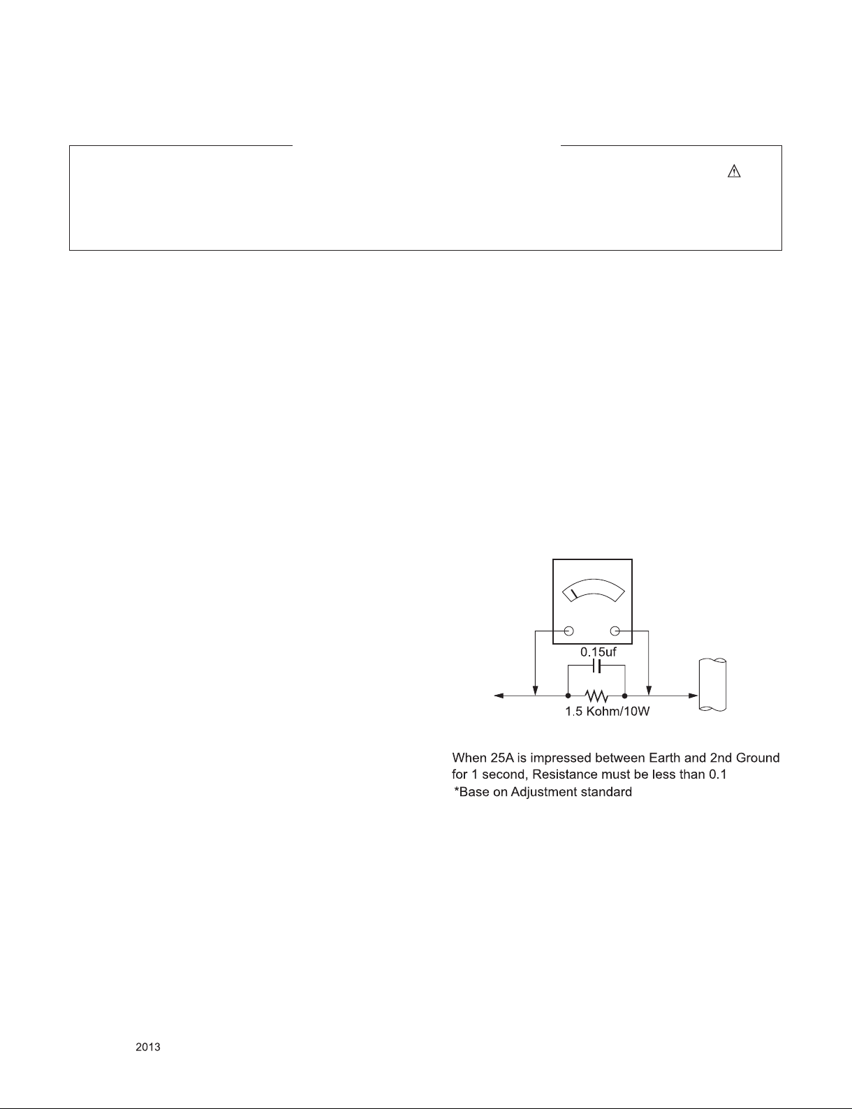
Leakage Current Hot Check (See below Figure)
Plug the AC cord directly into the AC outlet.
Do not use a line Isolation Transformer during this check.
Connect 1.5 K / 10 watt resistor in parallel with a 0.15 uF capacitor
between a known good earth ground (Water Pipe, Conduit, etc.)
and the exposed metallic parts.
Measure the AC voltage across the resistor using AC voltmeter
with 1000 ohms/volt or more sensitivity.
Reverse plug the AC cord into the AC outlet and repeat AC voltage
measurements for each exposed metallic part. Any voltage
measured must not exceed 0.75 volt RMS which is corresponds to
0.5 mA.
In case any measurement is out of the limits specified, there is
possibility of shock hazard and the set must be checked and
repaired before it is returned to the customer.
Leakage Current Hot Check circuit
Only for training and service purposes
- 3 -
LGE Internal Use OnlyCopyright © LG Electronics. Inc. All rights reserved.
SPECIFICATION
NOTE : Specifications and others are subject to change without notice for improvement
.
1. Application range
This spec sheet is applied all of the Monitor with LM13J
chassis.
2. Requirement for Test
Each part is tested as below without special appointment.
(1) Temperature:
25 °C ± 5 °C(77 °F ± 9 °F), CST: 40 °C ± 5 °C
(2) Relative Humidity: 65 % ± 10 %
(3) Power Voltage
: Standard input voltage (AC 100-240 V~, 50/60 Hz)
* Standard Voltage of each products is marked by models.
(4) Specification and performance of each parts are followed
ea ch dra wing and spe cificat ion by part n umber in
accordance with BOM.
(5) The receiver must be operated for about 5 minutes prior to
the adjustment.
3. Test method
(1) Performance: LGE TV test method followed
(2) Demanded other specification
- Safety : MIC Class A
- EMC : MIC Class A
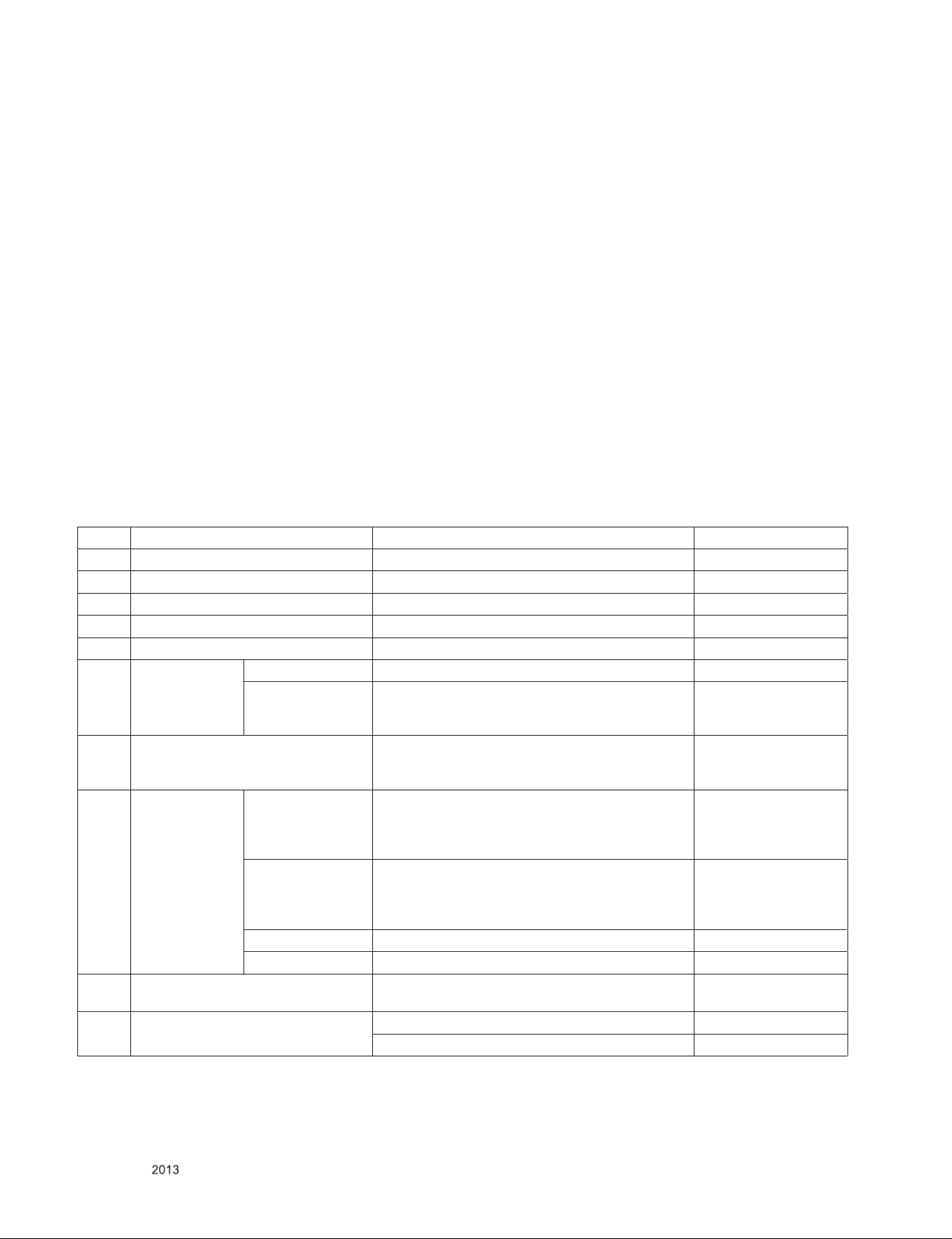
4. Module General Specification
(1) 23ET83
No Item Content Remark
1 Customer BRAND
2 User Model Name 23ET83
3 Sale region Refer to Sufx standard
4 Feature 23” Multi touch Wide LCD MONITOR
5 Chassis Name LM13J
6 General Scope External SW &Adj. Menu, My-Key , Function, Auto, input/Exit, Power
Function OSD,DDC2B,DDC2AB, HDCP, Control Lock,
Original Ratio / Wide, Black level, Super Energy
Saving
7 Power Code Length : 1.0±0.05 M
Shape : Wall-out
Color : Black
8 Cable Signal Cable
(D-SUB
USB cable Length: 1.87m
Audio Length : ,Shape : ,Color: ,Pin Do not Support
TV Length : ,Shape : ,Color: ,Pin Do not Support
9 Power(Power Update) Input: AC100~240V 50~60Hz,1.0A Max
10 Applying module list P/No : EAJ62311001
Length : 1.5m
Shape : Detachable Type
Color : Black
Pin : Triple Row, 15 Pin D-Sub
Shape : Detachable Type
Color: BLACK
Pin : 4P
Output: DC 19V 1.3 A
Specication : LM230WF3-SLK1
Refer to Sufx standard
and power cord table
Refer to Sufx standard
Refer to Sufx standard
Refer to Sufx standard
Only for training and service purposes
- 4 -
LGE Internal Use OnlyCopyright © LG Electronics. Inc. All rights reserved.

ADJUSTMENT INSTRUCTION
1. Application Range
This spec. sheet applies to LM13J chassis applied Monitor all
models manufactured in TV factory.
2. Designation
(1) Th e ad justm ent is accord ing to the order whic h is
designated and which must be followed, according to the
plan which can be changed only on agreeing.
(2) Power Adjustment: Free Voltage
(3) Magnetic Field Condition: Nil.
(4) Input signal Unit: Product Specification Standard
(5) Reserve after operation: Above 5 Minutes (Heat Run)
Temperature : at 25 °C ± 5 °C
Relative humidity : 65 % ± 10 %
Input voltage : 100 V~ 240 V, 50/60Hz
(6) Adju stment equ ipments: Color Ana lyzer (CA-210 or
CA-110), DDC Adjustment Jig equipment,
3. Adjustment
3.1. Overview
Use factory automation equipment and adjust automatic
movement. But, do via passivity adjust in error occurrence.
3.2. Adjustment order
(refer to th e Ad justment st andard and ad ju stment
command table)
3.2.1. Board Assembly Line
■ Connect input signal to 15pin D-sub.
■ Ready for adjustment : check whether adjustment command
works normally or not and the operating state of each mode.
■ Check the display state of gray color when 256 gray scale
pattern is embodied.
■ Read by EEPROM Read Command to check whether initial
value is correct or not.
3.2.2 Total Assembly Line
■ Input analog signal. (1920x1080@60Hz)
■ Write HDCP Key to EEPROM(24C16) by using DDC2AB
protocol & HDCP Adjusting Jig equipment [ Address 0xAC
80, 289 bytes ]
■ If error is occurred, write and check again.
■ Ready : Heat-run during 5 minutes in the state with signal
■ Connect input signal to D-sub.
■ Default value before adjustment :
Energy saving : off , Brightness “100(Max)”
3.2.3.
Adjustment of Horizontal/Verticality screen
position, Clock and Clock Phase at each Mode.
■ There is no special factory mode adjustment.
Writing initial value of EEPROM in Board Assembly line is
adjusting Preset Mode an d Reset mode. (EEPROM is
initialized when AC Power is ON first.)
■ If the change of FOS data is needed after M.P, it is possible
by writing Mode Data with EEPROM write command or
modifying the Mode Data in MICOM itself.
3.2.4. Color coordinates adjustment
and Luminance adjustment.
3.2.4.1. Color coordinates adjustment
■ Monitor Contrast / Brightness
- Energy saving : off
- Contrast : 70
- Brightness : 100(Max)
■ CA-110/CA-210 :
Set “Channel 7”-> CA-110: channel: 8. CA-210: channel 14
■ Signal Generator :
At cut-off and drive -> 16 step pattern for ADC
- Output Voltage : 700 mVp-p
- Output Mode : MSPG Timing : 126( 1920x1080 + 60Hz )
mode Setting.
3.2.4.2. Adjustment : Board Assembly Line
- 23ET83 model use internal ADC, no need connect D-SUB
cable
- Internal ADC steps as below
- On AC power on with Aging mode, checking the ADC values
and then decide to do or not,
• Read ADC OFFSET and GAIN flags from 0xA6 0xFD, 0xFE
on NVRAM
• If those values are not 0xAA on Aging mode, must do
internal ADC calibration.
• If the result of internal ADC calibration is OK, save the ADC
result and make the OFFSET and GAIN flags to 0xAA and
make the Internal_ADC flag to INTERNAL.
• Display the result of ADC on Aging Mode OSD and Service
OSD
- If don’t use internal ADC, please follow below step
■ Input 16 step pattern for ADC (Mode12, pattern 11/ MSPG :
timing 126, pattern 29). (Video level : 700 mVp-p)
■ Adjust by commanding AUTO_COLOR_ADJUST
■ Confirm “Success” message in Screen or Check the data of
0xFD, 0xFE address of EEPROM(0XA6) is 0xAA after
waiting 5 seconds
■ If there is “FAULT” message or the data of 0xFD, 0xFE
address of EEPROM(0xA6) is not 0xAA, do adjust again
■ If all Adjustment is completed, the values of Warm(6500K),
User Color and Cool(Cool(9300K)) are saved automatically.
3.2.4.3. Confirm at Total Assembly Line: adjustment
■ Check the data of 0xFD, 0xFE address of EEPROM(0xA6)
is 0xAA.
■ If the data 0xFD, 0xFE address of EEPROM(0xA6) is not
0xAA, do adjust again by 3.2.4.2.
(Caution) Must keep power-on more than 3 seconds after AC
Power-on first time.
Only for training and service purposes
- 5 -
LGE Internal Use OnlyCopyright © LG Electronics. Inc. All rights reserved.
3.2.4.4. confirm PRESET Warm(6500K) Color coordinates
Don’t need to adjust Warm(6500K) color.
Warm(6500K) color R, G, B gain are saved by FW calculation.
23ET83
-. R Gain : 6500K_R = 128
-. G Gain : 6500K_G = 128
-. B Gain : 6500K_B = 128
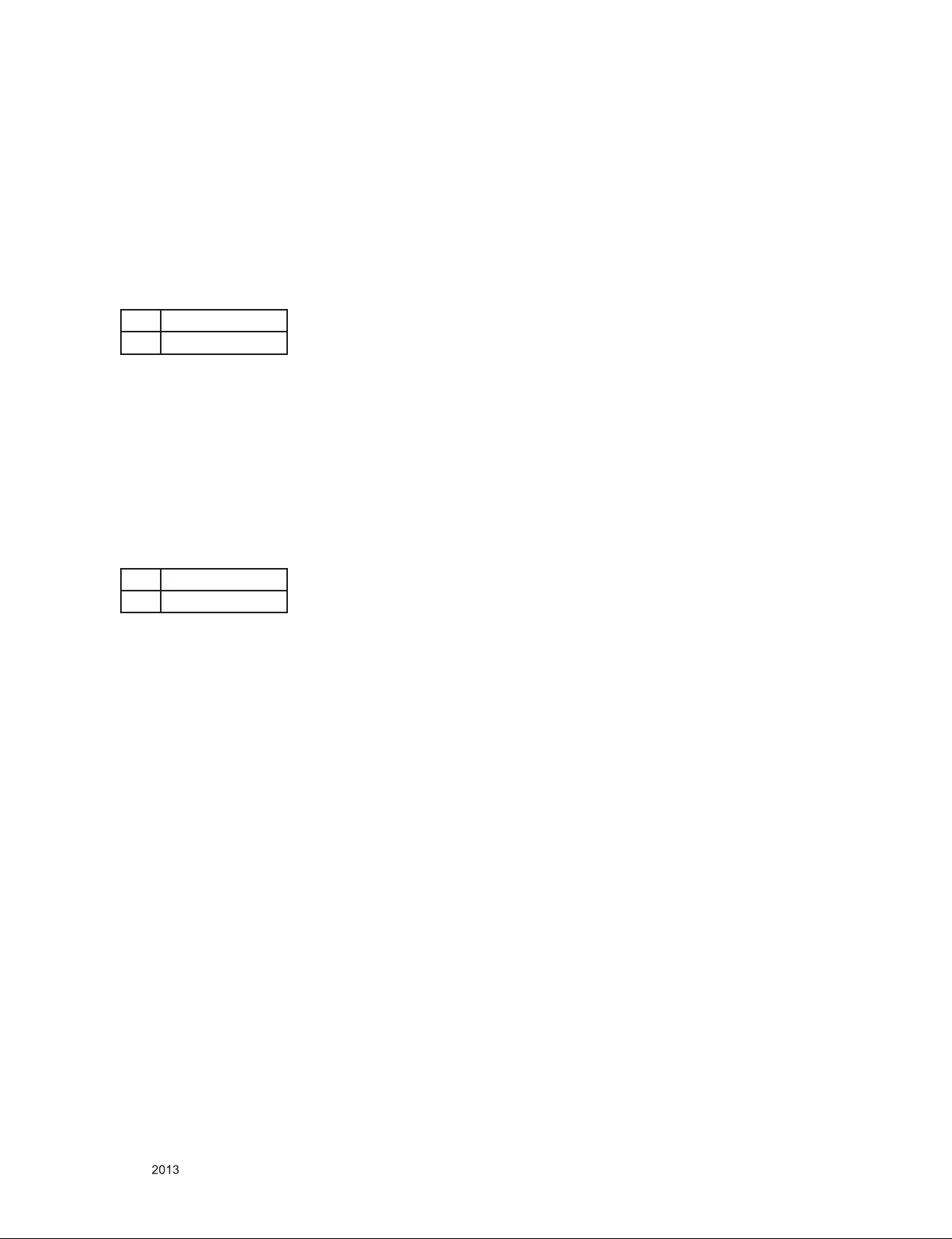
■ Check the Warm(6500K) whether meet x/y color coordinate
as below or not:
X 0.313 ± 0.03
Y 0.329 ± 0.03
3.2.4.5. confirm PRESET Cool(9300K) Color coordinates.
Don’t need to adjust Cool(9300K) color.
Cool(9300K) color R, G, B gain are saved by FW calculation.
23ET83
-. R Gain : 9300K_R = 6500K_R – 17
-. G Gain : 9300K_G = 6500K_R – 16
-. B Gain : 9300K_B = 6500K_R
■ Check the Warm(9300K) whether meet x/y color coordinate
as below or not:
3.2.5.3. Confirm Auto adjustment operation.
■ Input Analog 1 Dot on/off & Rectangle Pattern at Mode
12(1920x1080@60Hz / MSPG 126)
■ Con fi rm a dj us tm en t op er ation by c ha nging Clock,
Phase,H/V Position.
■ Check Clock, Phase by pressing AUTO Key.
■ Confirm first set of new lot by periods
3.2.5.4 Other quality
■ Confirm that each items satisfy under standard condition
that was written product spec.
■ Confirm Applying Module & MICOM Setting -> Confirm with
Service OSD
■ Confirm at Service OSD by “Menu + Power key” on .(from
Power off)
■ Confirm first set of new lot by period s, and co nfirm
periodically when there is Process change or Adjustment
setting change.
3.2.5.5. OSD & Adj ustment de vice Confi rmation : Co nfirm
operation mentioned as product spec.
■ Vary Brightness and Contrast and confirm the variation of
Luminance and display status.
■ Operate the f-engine function and confirm variation of
Luminance.
■ Make sure to do FACTORY RESET after confirmation of
OSD function.
X 0.283 ± 0.03
Y 0.298 ± 0.03
3.2.4.6. Confirm User color coordinates .
■ C onf ir m W het he r U se r c olo r is sa ved s ame a s
Warm(6500K).
■ A ft er co nf ir mi ng Colo r coordina te s, Must return t o
Warm(6500K)
■ Confirm whether user color is 50. If the value of user
color(R/G/B) is 30, do adjust again by 3.2.4.2.
3.2.5. Confirm Operation state.
3.2.5.1 Operation mode : Confirm whether each appointed mode
operate correctly or not.
3.2.5.2 Confirmation of Adjustment condition and operation :
Co nfirm whe ther it meet Auto/ Manua l equipement
Adjustment standard or not.
■ Confirm Analog screen state :
Confirm screen state at below mode.
Appointment mode :
640*480 @60Hz (Timing 35), 800*600@75Hz(Timing 48)
1024*768@60Hz(Timing 60), 1280*1024@60Hz(Timing
99), 1680*1050@60Hz(Timing 122),
1920*1080@60HZ(Timing 126)
SMPTE pattern(No,17/Check 0%,5%,95%,100%) –Mode
can be added.
■ Check HDCP signal screen by using Video generator that
generate HDCP signal
3.2.5.6. Confirm the display state by inputting 8 color Bar Pattern
& 256 Gray Scale pattern.
3.2.5.7. DPM operation confirmation : Check if Power LED Color
and Power Consumption operates as standard.
■ Measurement Condition : 230V@ 50Hz (Analog)
■ Confirm DPM operation at the state of screen without Video
Signal.(refer to Spec at Page 11)
3.2.5.8. DDC EDID Write
- HDMI part EDID data
- 23ET83 No need input HDMI EDID on the line, F/W include
HDMI EDID, aging on MO DE If AC ON, HDMI EDID
automatic load to EEPROM(24C02).
- After input D-sub EDID, Please send command “0x77 0 1” to
update the S/N of HDMI1, HDMI2 EDID, and then check the
address 0xE8 data. If Serial number is updated properly, it
should be 0xDD.
Other model if need input EDID on the line, please refer below
steps:
■ Confirm whether module selection is correct or not on the
self-diagnostics OSD with signal cable disconnected.
■ Connect HDMI Signal Cable to DVI-D wafer.
■ Write EDID DATA to EEPROM(24C02) by using DDC2B
protocol.
■ Check whether written EDID data is correct or not.
Only for training and service purposes
- 6 -
LGE Internal Use OnlyCopyright © LG Electronics. Inc. All rights reserved.
 Loading...