

LG 23CAV42K-B, 23CAV42K-BL Owner’s Manual

English
OWNER'S MANUAL
CLOUD MONITOR
(LED LCD MONITOR)
Please read the safety information carefully before using the product.
CLOUD Monitor(LED LCD Monitor) Model
23CAV42K
www.lg.com

English
ENG
Table of Contents
2
TABLE OF CONTENTS
3 ASSEMBLING AND
PREPARING
3 Unpacking
4 Parts and buttons
6 Lifting and moving the Monitor
6 Setting Up the Monitor set
6 - Attaching the Stand Base
7 - Mounting on a table
7 - Adjusting the angle
8 - Adjusting the stand height
8 - Using the Kensington locking device
9 - Detaching the stand base
9 - Detaching the stand body
10 - Swivel stand
10 - Using the Pivot function
11 - Installing the wall mount plate
11 - Mounting on a wall
13 USING THE MONITOR SET
27 PRODUCT SPECIFICATION
28 Preset Mode
28 Power Indicator
29 PROPER POSTURE
29 Proper posture for using the monitor
30 USING CLOUD SOLUTION
13 Connecting Input Signal Cable
13 - D-SUB IN connection - PC
14 - DVI connection
15 Connecting LAN/Peripherals
15 - LAN connection
16 - Peripheral device connection
17 - Self Image Adjustment
18 CUSTOMIZING SETTINGS
19 Customizing Settings
19 - Menu Settings
20 - PICTURE
21 - COLOR
22 - DISPLAY
23 - OTHERS
24 - VOLUME
25 TROUBLESHOOTING
ASSEMBLING AND PREPARING
ASSEMBLING AND PREPARING
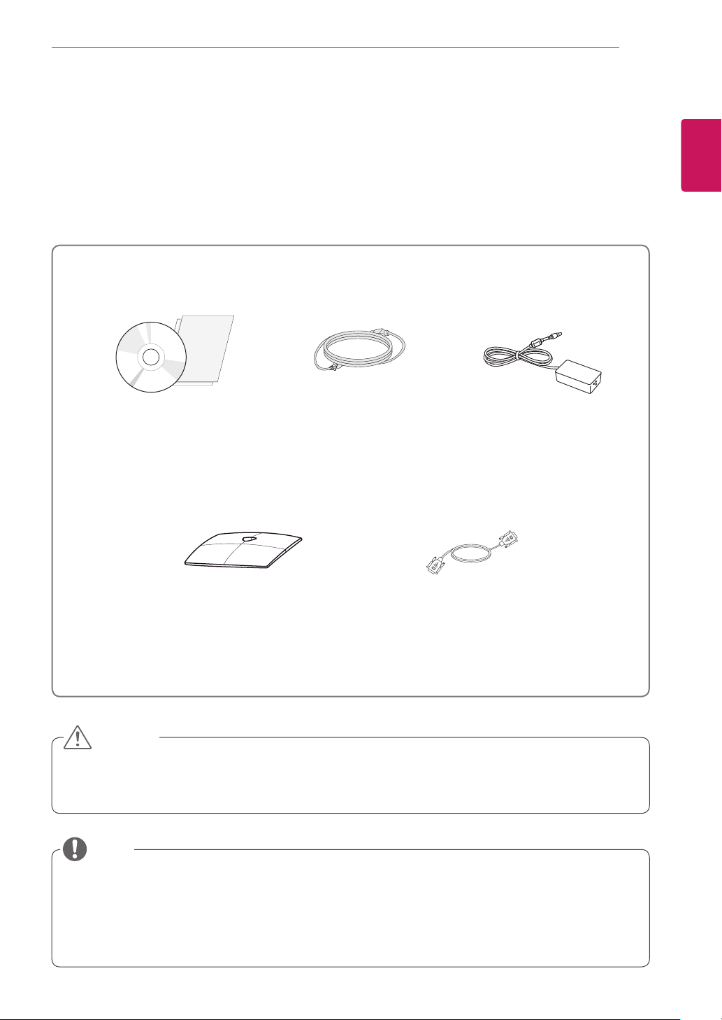
Unpacking
Please check whether all the components are included in the box before using the product. If there are
missing components, contact the retail store where you purchased the product. Note that the product and
components may look different from those shown here.
3
English
ENG
Power CordUser Manual/Card
Stand Base
15-pin D-SUB Signal Cable
(This cable is not included in all
CAUTION
Only use an approved LG power adapter.
y
Damage caused by other power adapters is not covered by warranty.
y
Adaptor
counties)
NOTE
Note that the components may look different from those shown here.
y
Without prior notice, all information and specifications in this manual are subject to change to improve
y
the performance of the product.
To purchase optional accessories, visit an electronics store or online shopping site or contact the retail
y
store where you purchased the product.
English
ENG
ASSEMBLING AND PREPARING
4
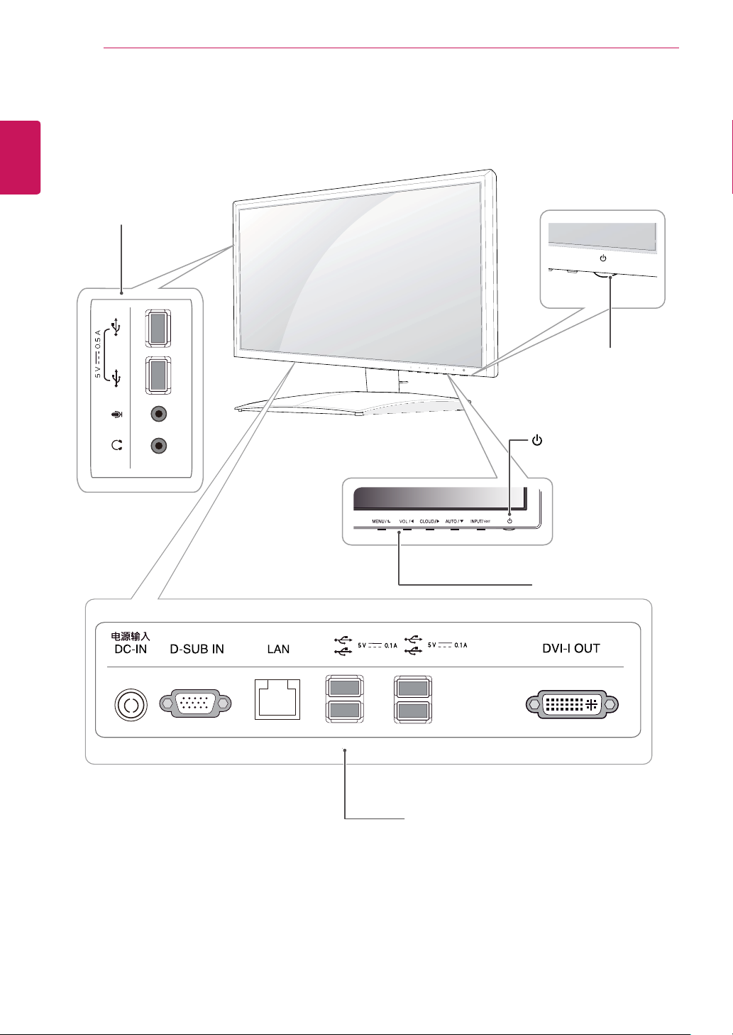
Parts and buttons
Input Connectors
(See p.to 16 )
Power Indicator
LED On : Power is on
y
LED Off: Power is off
y
(Power Button)
Front Side Buttons
1
Input Connectors (See p.13 to 16)
1
ASSEMBLING AND PREPARING
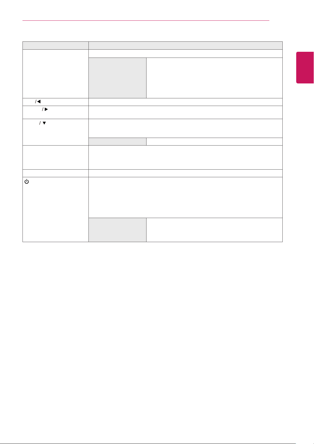
Button Description
MENU Activates the main menu.
OSD Lock/Unlock
Functions
VOL
CLOUD
AUTO To adjust the monitor settings, press the AUTO button on the MONITOR SETUP OSD
INPUT Allows selection of the input signal.
EXIT Exits the OSD menu.
(Power Button)
Adjust the volume of the monitor.(only works in Cloud mode)/the left arrow key.
Disconnects the connection when the key is pressed for a few seconds while in Cloud
mode;the right arrow key.
menu (only supported for analog signal).
For optimal screen display, use the following resolution.
Optimal Resolution
yIf you connect the monitor to a computer using a D-SUB cable, select either the
CLOUD or D-SUB input signal.
yThe initial input signal is D-SUB.
yD-SUB Input: Power On/Off
yCLOUD Input
Monitor Off: Press the power button once then the monitor will be turned off after 5
seconds.
CLOUD Off: Press the power button twice then the monitor and CLOUD connection
will be disabled.
CLOUD On: Press the power button.
Power Indicator
Locks/unlocks the OSD screen.
yTo lock the OSD screen, press and hold the MENU button
for several seconds. The "OSD LOCKED" message will be
displayed and the screen will be locked.
yTo unlock the OSD screen, press and hold the MENU
button again for several seconds. The "OSD UNLOCKED"
message will be displayed and the screen will be unlocked.
1920 x 1080
When the monitor is in operating mode, the power indicator
will turn Red (on mode).
When the monitor is in power saving mode, the power indicator will blink Red.
5
English
ENG
ASSEMBLING AND PREPARING
6
English
ENG
Lifting and moving the Monitor
Please heed the following information when
moving the monitor.
CAUTION
Avoid touching the screen at all times, as this
y
may result in damage to the screen or pixels .
It is recommended to move the Monitor in
y
the box or packing material that the Monitor
originally came in.
Before moving or lifting the Monitor,
y
disconnect the power cord and all cables.
Hold the top and bottom of the Monitor frame
y
firmly. Make sure not to hold the transparent
part area.
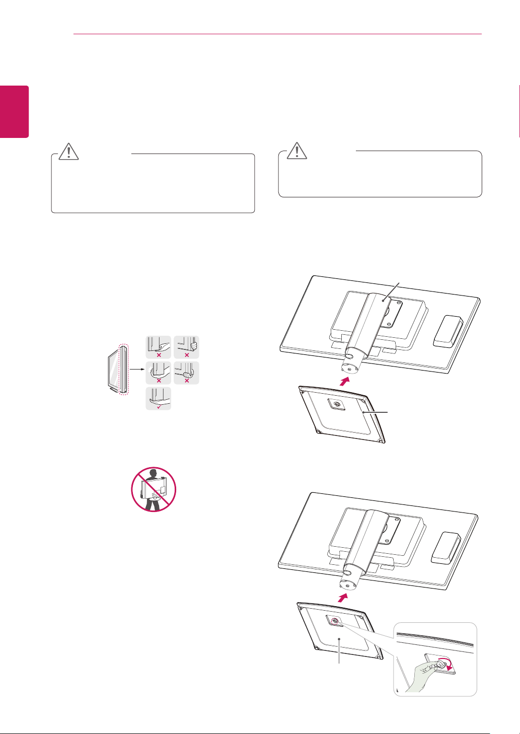
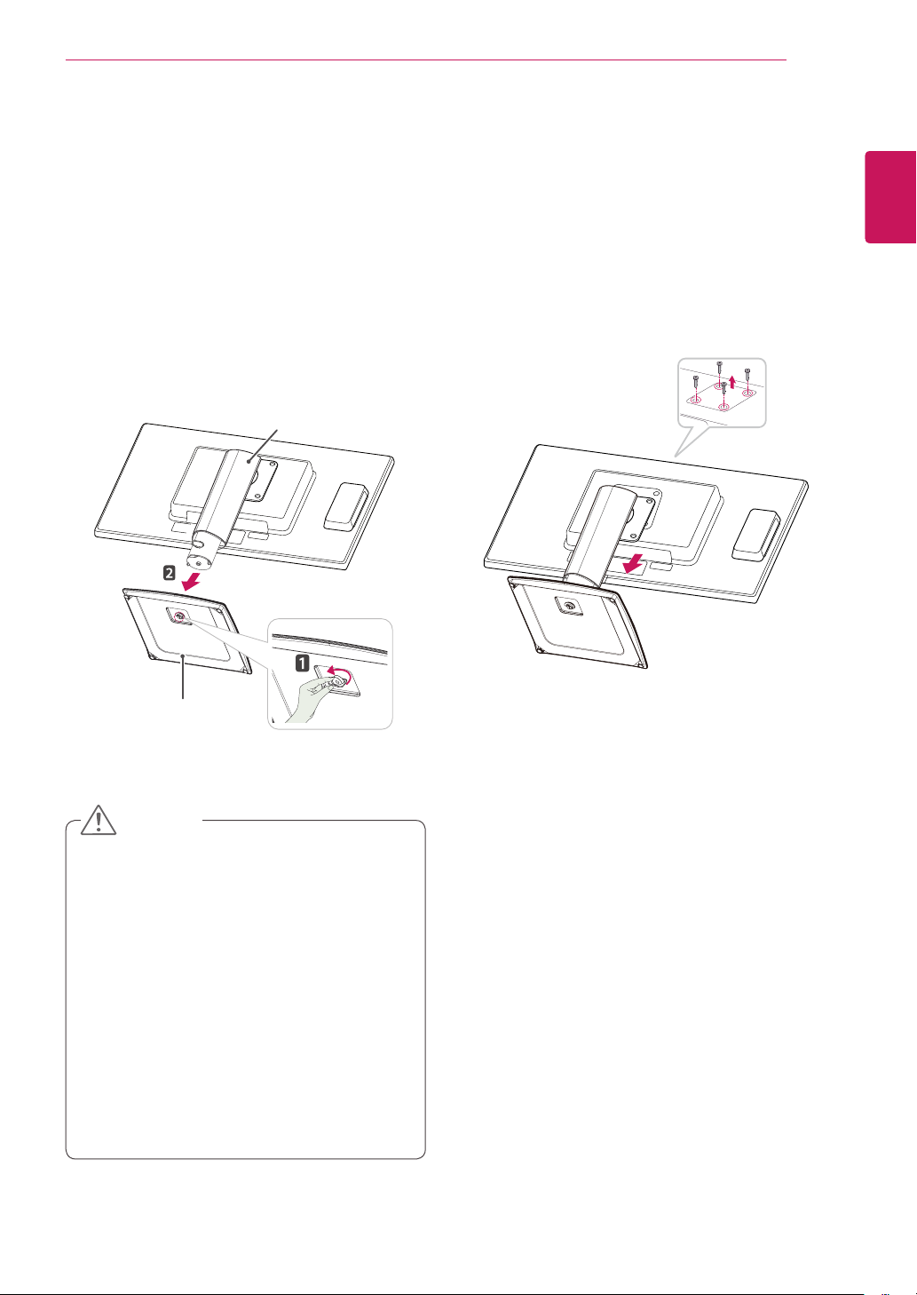
Setting Up the Monitor set
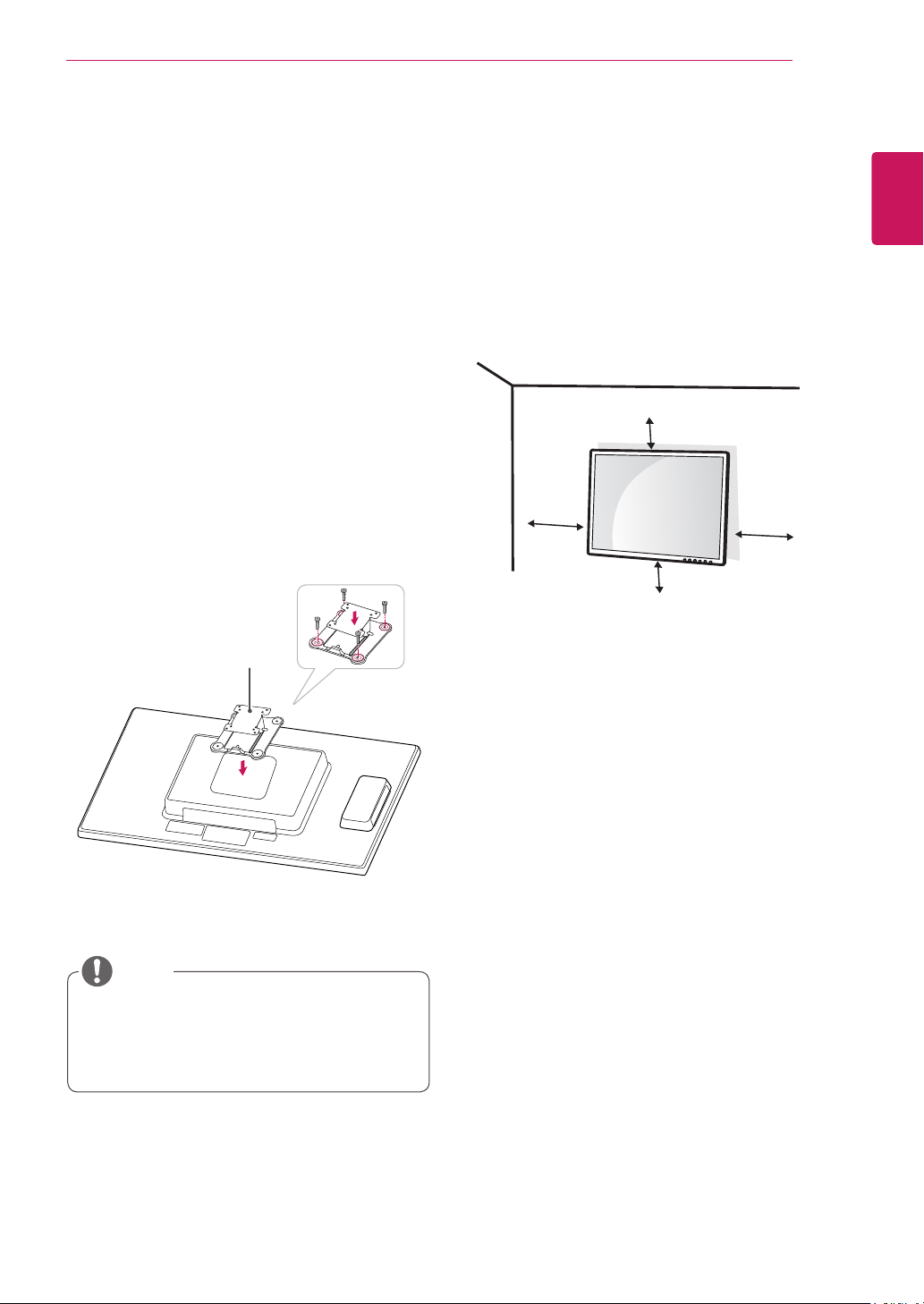
Attaching the Stand Base
Place the monitor's screen face down.
1
CAUTION
To protect the screen from scratches, cover
y
the surface with a soft cloth.
Check the
2
the stand body, then mount the
the
position (at the front and rear)
stand body
as shown in the figure.
Stand Body
stand base
of
on
When holding the Monitor, the screen should
y
face away from you to prevent the screen
from scratches.
When transporting the Monitor, do not
y
expose the Monitor to jolts or excessive
vibration.
When transporting the Monitor, keep the
y
Monitor upright, never turn the Monitor on its
side, or tilt towards the left or right.
Stand Base
Using a coin, turn the screw clockwise to se-
3
cure the
stand base.
Stand Base
ASSEMBLING AND PREPARING
7
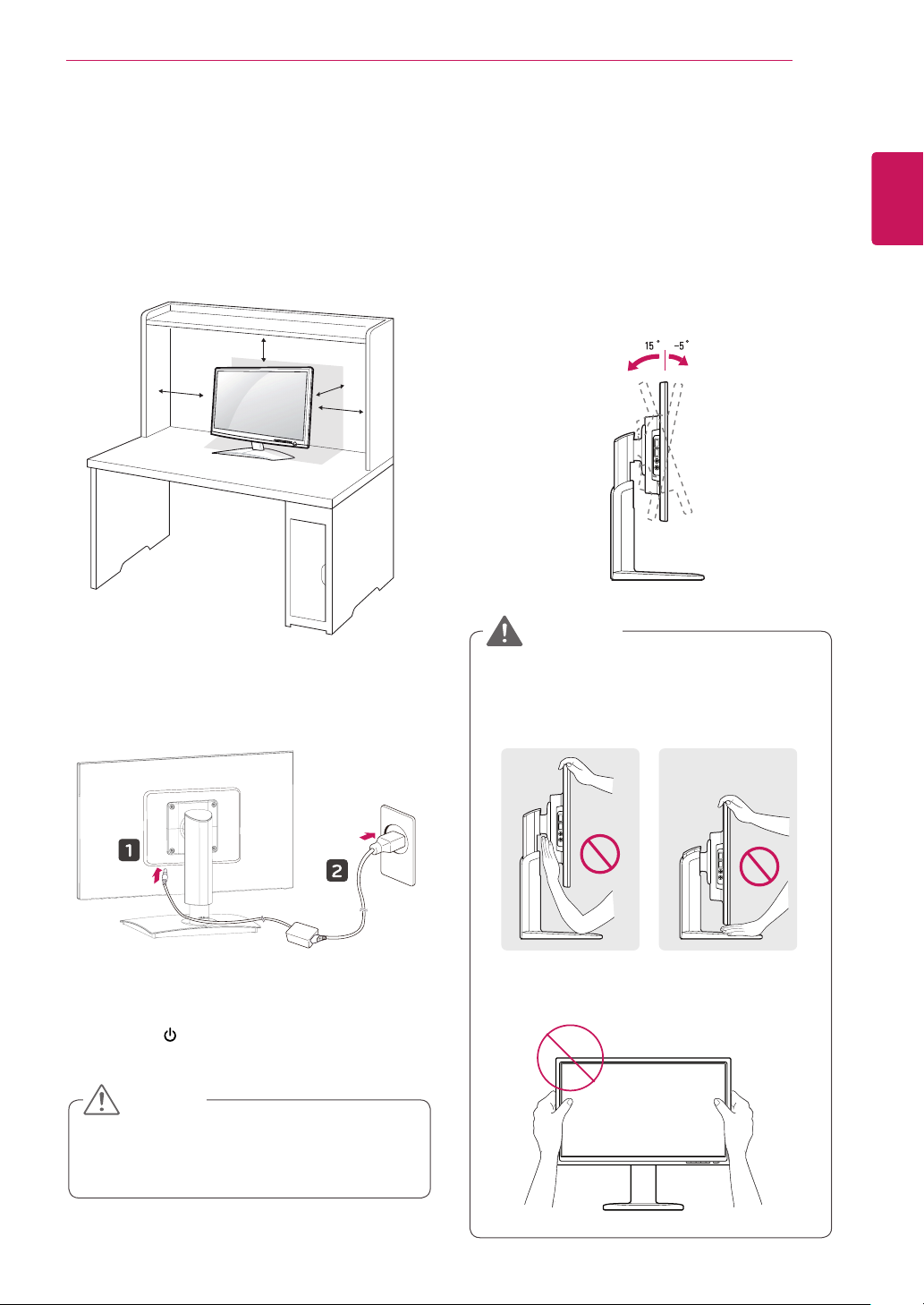
Mounting on a table
Lift the monitor and place it on the table in an
1
upright position.
100 mm
100 mm
100 mm
away from the wall to
100 mm
100 mm
Install at least
ensure sufficient ventilation.
Adjusting the angle
Place the monitor mounted on the stand base
1
in an upright position.
Adjust the angle of the screen. The angle of
2
the screen can be adjusted up to 5° forwards
and 15° backwards for a comfortable viewing
experience.
Front SideRear Side
WARNING
English
ENG
Connect the adaptor to the monitor, then plug
2
the power cord into the wall outlet.
Press the (Power) button on the front of the
3
monitor to turn on the monitor.
CAUTION
Unplug the power cord prior to moving or
y
installing the monitor. There is risk of electric
shock.
To avoid injury to the fingers when adjusting
y
the screen, do not hold the lower part of the
monitor's frame as illustrated below.
Be careful not to touch or press the screen
y
area when adjusting the angle of the monitor.
ASSEMBLING AND PREPARING
8
English
ENG
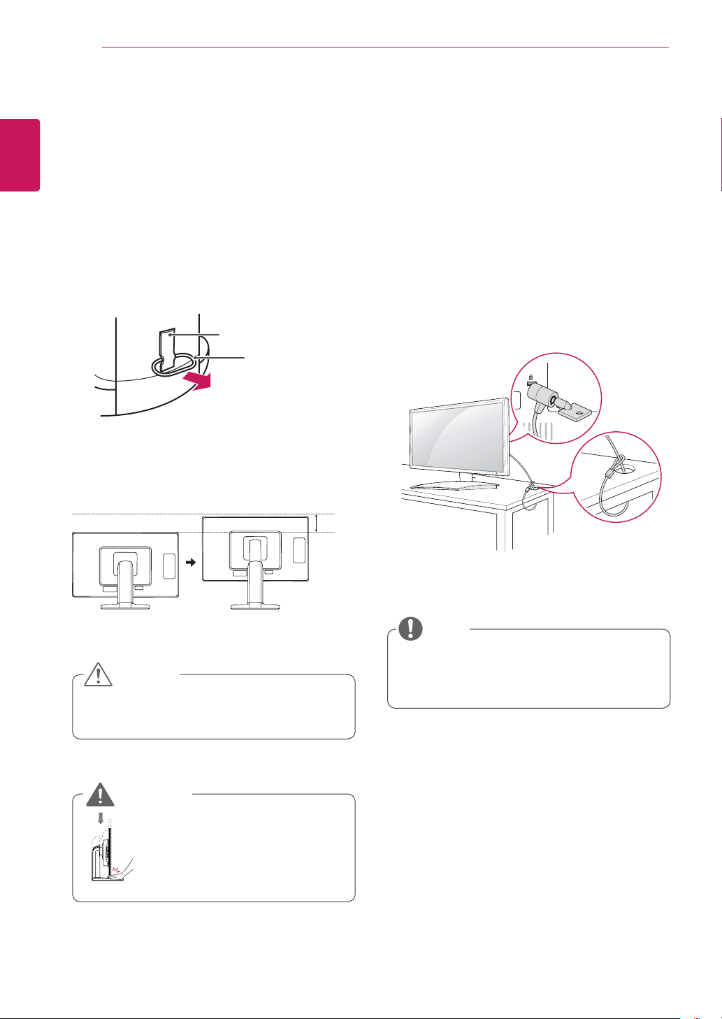
Adjusting the stand height
Place the monitor mounted on the stand base
1
in an upright position.
Remove the
2
of the
pin.
Stand Body
The height can be adjusted up to
3
tape
stand body,
attached at the bottom rear
then pull out the
Tape
Locking Pin
locking
130 mm
Using the Kensington locking device
The connector for the Kensington lock is located
on the rear of the monitor.
For more information on installation and usage,
refer to the Kensington lock user manual or visit
the website at http://www.kensington.com.
Connect the monitor to the table with the Kensing-
ton lock cable.
.
130.0mm
CAUTION
Once the pin is removed, it is not necessary
y
to re-insert it to adjust the height.
WARNING
Do not put your finger be-
y
tween the screen and the
base (chassis) when adjusting the screen's height.
NOTE
Using the Kensington lock is optional. The
y
accessories can be purchased at your local
electronics store.
ASSEMBLING AND PREPARING
9
Detaching the stand base
Place the monitor's screen face down.
1
To protect the screen from scratches, cover the
surface with a soft cloth.
Using a coin, turn the screw in the stand base
2
counterclockwise. Detach the
stand body
the
.
stand base
Stand Body
from
Detaching the stand body
Place the monitor's screen face down. To
1
protect the screen from scratches, cover the
surface with a soft cloth.
Using a screwdriver, remove the four screws
2
and detach the stand from the monitor.
English
ENG
Stand Base
CAUTION
The components appearing in the illustra-
y
tions may look different from the actual product.
Do not carry the monitor upside-down as this
y
may cause it to fall off its stand, resulting in
damage or injury.
To avoid damaging the screen when lifting
y
or moving the monitor, only hold the stand or
the plastic cover. This avoids putting unnecessary pressure on the screen.
Only remove the tape and the locking pin
y
when the monitor is mounted on the stand
base and is in an upright position. Otherwise,
the stand body may protrude, which may
lead to injury.
English
ENG
ASSEMBLING AND PREPARING
10
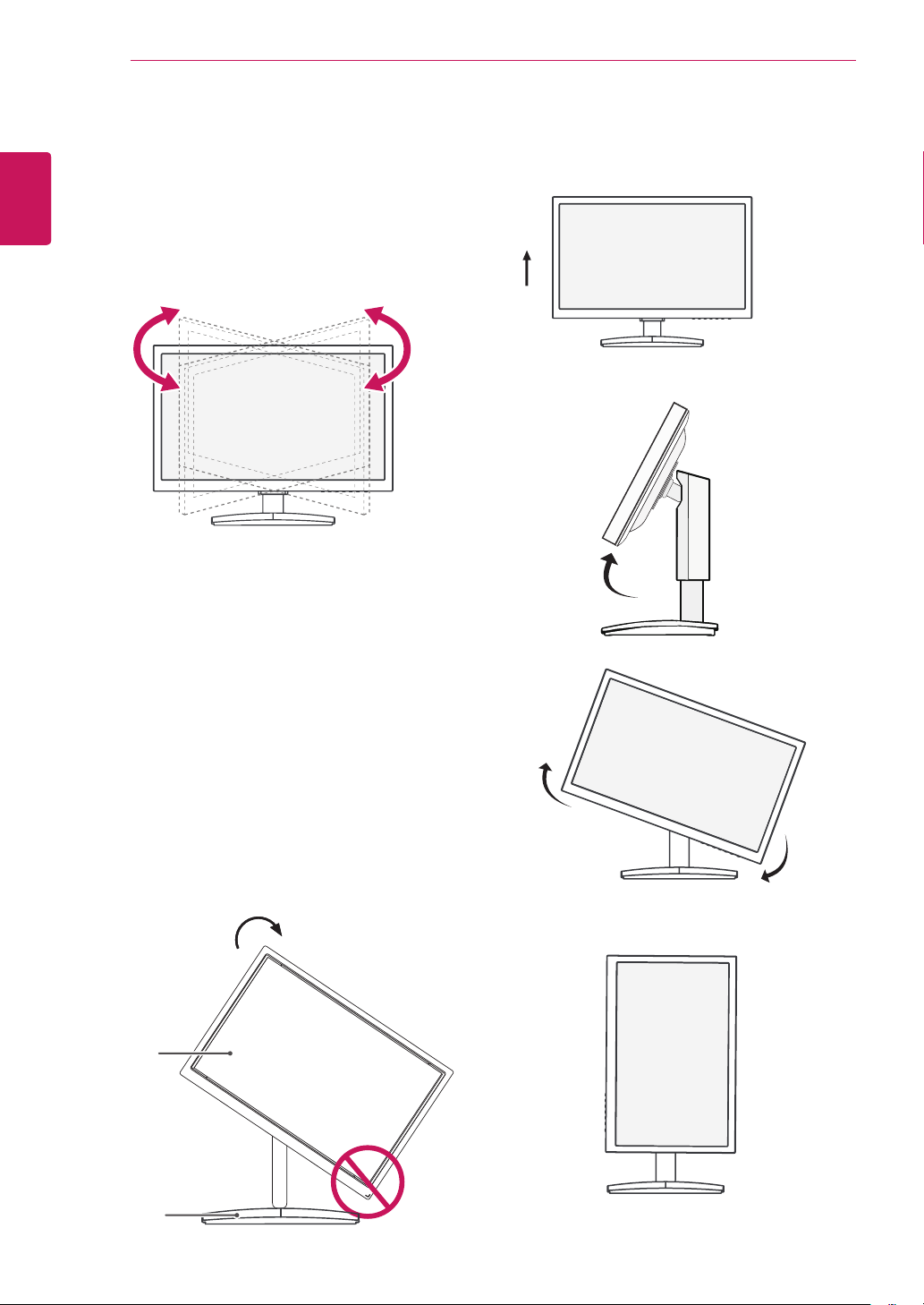
Swivel stand
Image shown may differ from your Monitor
y
set.
Swivel 90 degrees and adjust the angle of the
1
Monitor set to suit your view.
Be careful with the cables when rotating the
3
screen.
Using the Pivot function
The pivot function allows you to rotate the screen
90 degrees clockwise.
Lift the monitor to its highest height to utilize
1
the Pivot function.
Landscape & Portrait : You can rotate the panel
2
90° clockwise. Please be cautious and avoid
contact between the monitor head and the
Stand Base when rotating the screen to access
the Pivot function. If the monitor head touches
the Stand Base, then the Stand Base could
crack.
Head
section
Stand
section
ASSEMBLING AND PREPARING
11
Installing the wall mount plate
This monitor has a VESA compatible mount on the
back. Most mounts will require an LG mounting
plate.
Place the monitor's screen face down. To
1
protect the screen from scratches, cover the
surface with a soft cloth.
Place the wall mount plate on the monitor and
2
align it with the screw holes on the monitor.
Using a screwdriver, tighten the four screws to
3
fix the plate onto the monitor.
Mounting on a wall
Install the monitor at least 100 mm away from the
wall and leave about 100 mm of space at each
side of the monitor to ensure sufficient ventilation.
Detailed installation instructions can be obtained
from your local retail store. Please refer to the
manual to install and set up a tilting wall mounting
bracket.
100 mm
100 mm
100 mm
100 mm
English
ENG
Wall Mount Plate
NOTE
The wall mount plate is sold separately.
y
For more information on the installation, refer
y
to the wall mount plate's installation guide.
If you intend to mount the Monitor set to a wall,
attach Wall mounting interface (optional parts) to
the back of the set.
When you install the Monitor set using a wall
mounting interface (optional parts), attach it
carefully so it will not drop.
Please, Use the screw and wall mount interface
1
in accordance with VESA Standards.
If you use screw longer than standard, the
2
monitor might be damaged internally.
If you use improper screw, the product might be
3
damaged and drop from mounted position. In
this case, LG Electronics is not responsible for
it.
VESA compatible.
4
Please use VESA standard as below.
5
784.8 mm (30.9 inch) and under
y
* Wall Mount Pad Thickness : 2.6 mm
* Screw : Φ 4.0 mm x Pitch 0.7 mm x
Length 10 mm
787.4 mm (31.0 inch) and above
y
* Please use VESA standard wall mount pad
and screws.
ASSEMBLING AND PREPARING
12
English
ENG
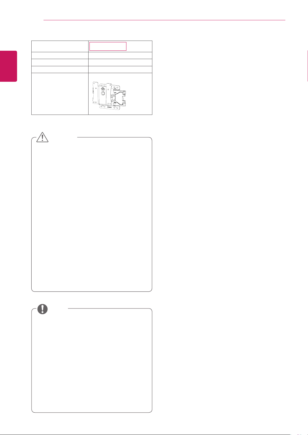
Model
VESA (A x B)
Stand Screw
Required Screw
Wall Mount Plate
(Optional)
23CAV42K
100 x 100
M4
4
LSW 149
CAUTION
Unplug the power cord before moving or in-
y
stalling the monitor to avoid electric shocks.
Installing the monitor on the ceiling or on a
y
slanted wall may result in the monitor falling
off, which could lead to injury. Please use
a LG wall mounting bracket when using a
VESA mount. For more information, contact
your local retail store or a qualified installer.
Applying excessive force when fastening
y
screws may cause damage to the monitor. Damage caused in this way will not be
covered by the product warranty.
Use the wall mounting bracket and screws
y
that conform to the VESA standard. Damage caused by the use or misuse of inappropriate components will not be covered
by the product warranty.
NOTE
Use the screws specified in the VESA stan-
y
dard.
The wall mount kit includes the installation
y
guide and necessary parts.
The wall mounting bracket is optional. The
y
accessories can be purchased at your local
retail store.
The length of the screw may differ for each
y
wall mounting bracket. Ensure the correct
length of the screw is used.
For more information, please refer to the user
y
manual for the wall mounting bracket.
USING THE MONITOR SET
USING THE MONITOR SET
13
English
ENG
Connecting Input Signal Cable
This monitor supports the *Plug and Play
y
feature.
*Plug and Play: A feature that allows you to
add a device to your computer, without having
to reconfigure anything or install any manual
drivers.
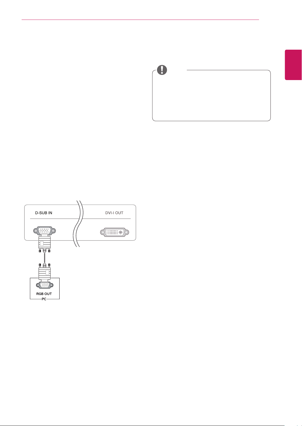
D-SUB IN connection - PC
D-SUB IN transfers analog video signals from the
PC to the monitor.
Connect the monitor to the PC using the provided
15-pin D-SUB signal cable as illustrated below.
NOTE
Apple Adapter
y
An adapter may be needed for Apple
computers. This adapter can be purchased
from Apple.
USING THE MONITOR SET
14
English
ENG
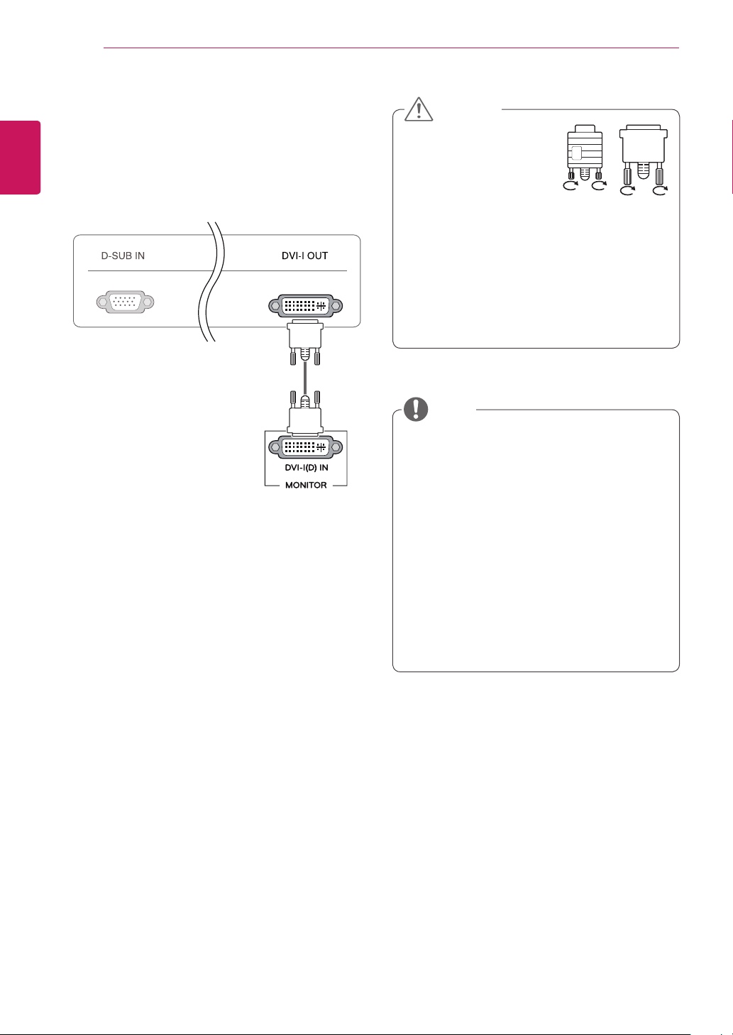
DVI connection
Transfers digital video signals from the Cloud Monitor to an extended monitor.
Connect the Cloud Monitor to an extended monitor
using a DVI cable.
CAUTION
Connect the input signal
y
cable and tighten in the
direction of the arrow. To
prevent disconnection
secure the cable tightly.
Do not press on the screen for a prolonged
y
time. This may cause image distortion.
Do not display a still image on the screen
y
for a prolonged time. This may cause image
retention. If possible, use the screen saver.
NOTE
To connect the monitor to a computer, use
y
the appropriate signal cable (LAN and DSUB).
A converter can be used to convert the DVI-I
y
input signal to D-SUB input signal.
When connecting the power cord to the out-
y
let, use a grounded (3-hole) multi-socket or a
grounded wall outlet.
The monitor may flicker when turned on in an
y
area of low temperature. This is normal.
Sometimes red, green or blue spots may ap-
y
pear on the screen. This is normal.
USING THE MONITOR SET
15
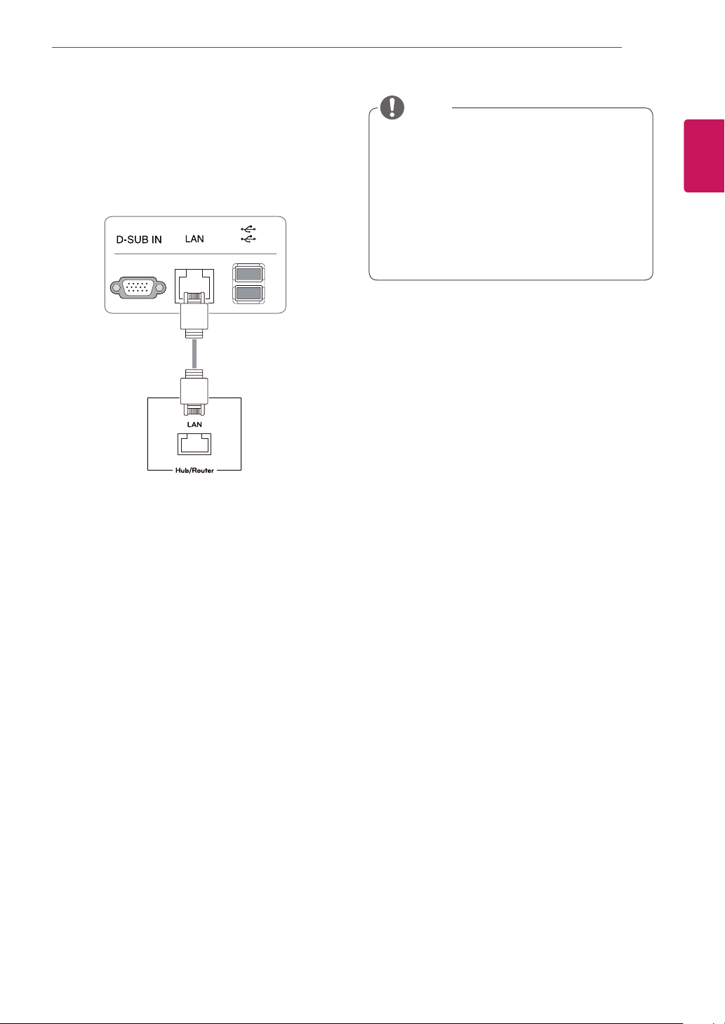
Connecting LAN/Peripherals
LAN connection
Connect the router or switch to the monitor using a
LAN cable as illustrated below.
NOTE
The LAN cable is sold separately.
y
The following LAN cable type can be used:
y
Standard: IEEE 802.3 ETHERNET
If a device is connected into the earphone
y
out port via a LAN cable, you can adjust the
volume with the volume icon on PC taskbar.
Connect the LAN cable and the peripheral
y
devices prior to booting up the PC.
English
ENG
USING THE MONITOR SET
16
English
ENG
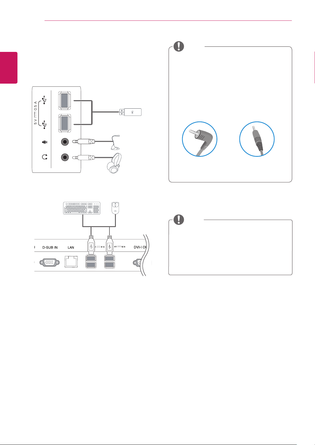
Peripheral device connection
Connect peripheral devices to the monitor using
USB, microphone and headphone ports.
Left
NOTE
Peripheral devices are sold separately.
y
The USB ports on the left and bottom of the
y
monitor can be used to connect the keyboard, mouse, and other USB devices.
Cables with angled plugs may have clear-
y
ance issues, use straight plugs when possible.
Angle Type Straight Type
NOTE
Bottom
Headphones, speakers or microphone may
y
1
1
not work normally, depending on the server
PC settings.
Virtual solutions may affect the functions or
y
speed of the specific USB storage device.
 Loading...