

Page 1

LG
Room
Air Conditioner
SERVICE MANUAL
LG
CAUTION
website http://www.lgservice.com
• BEFORE SERVICING THE UNIT, READ THE SAFETY
PRECAUTIONS IN THIS MANUAL.
• ONLY FOR AUTHORIZED SERVICE PERSONNEL.
Page 2

—2—
1. PREFACE
1.1 SPECIFICATIONS ..........................................3
1.2 FEATURES AND BENEFITS..........................4
1.3 CONTROL LOCATIONS.................................6
1.4 ADDITIONAL CONTROLS..............................7
2.
DISASSEMBLY INSTRUCTIONS
2.1 MECHANICAL PARTS....................................9
2.1.1 FRONT GRILLE.....................................9
2.1.2 CONTROL BOX (Half-Disassembly)....10
2.1.3 CONTROL BOX (Full-Disassembly)....10
2.2 AIR HANDLING PARTS................................11
2.2.1 HEATER ASSEMBLY AND CROSS
FLOW FAN...........................................11
2.2.2 FAN......................................................11
2.2.3 SHROUD..............................................12
2.3 ELECTRICAL PARTS...................................12
2.3.1 OUTDOOR MOTOR ............................12
2.3.2 INDOOR MOTOR ................................12
2.3.3 COMPRESSOR...................................12
2.3.4 CAPACITOR........................................12
2.3.5 POWER CORD....................................13
2.3.6 P.C.B....................................................13
2.4 REFRIGERATION CYCLE............................14
2.4.1 CONDENSER......................................14
2.4.2 EVAPORATOR....................................14
2.4.3 CAPILLARY TUBE...............................14
3.
INSTALLATION
3.1 HOW TO INSTALL THE UNIT ......................17
3.2 SUGGESTED TOOL REQUIREMENTS.......18
3.2.1 PREPARATION OF SLEEVE ..............18
3.2.2 PREPARATION OF THE FRONT
GRILLE ................................................18
3.2.3 UNIT INSTALLATION..........................19
3.3 ELECTRICAL REQUIREMENTS..................20
3.3.1
ELECTRICAL DATA (FOR 230V/208 MODEL)........
20
3.3.2 ELECTRICAL SAFETY
............................
20
4.
FERFORMANCE DATA
.................................
21
5.
TROUBLESHOOTING GUIDE
5.1 OUTSIDE DIMENSIONS...............................26
5.2 PIPING SYSTEM ..........................................26
5.3 TROUBLESHOOTING GUIDE......................27
6. SCHEMATIC DIAGRAM.....................32
7. EXPLODED VIEW..................................33
8. REPLACEMENT PARTS LIST.......34
1. PREFACE
This
SERVICE MANUAL provides various service information, including the mechanical and electrical
parts etc. This room air conditioner was manufactured and assembled under a strict quality control system.
The refrigerant is charged at the factory. Be sure to read the safety precautions prior to servicing the unit.
1.1 SAFETY PRECAUTIONS
1. When servicing the unit, set the ROTARY SWITCH
or POWER SWITCH to OFF(O) and unplug the
power cord.
2. Observe the original lead dress.
If a short circuit is found, replace all parts which
have been overheated or damaged by the short
circuit.
3. After servicing the unit, make an insulation
resistance test to protect the customer from being
exposed to shock hazards.
1.2
INSULATION RESISTANCE TEST
1. Unplug the power cord and connect a jumper
between 2 pins (black and white).
2. The grounding conductor (green or green & yellow)
is to be open.
3. Measure the resistance value with an ohm meter
between the jumpered lead and each exposed
metallic part on the equipment at all the positions
(except OFF or O) of the ROTARY SWITCH.
4. The value should be over 2MΩ.
CONTENTS
Page 3
—3—
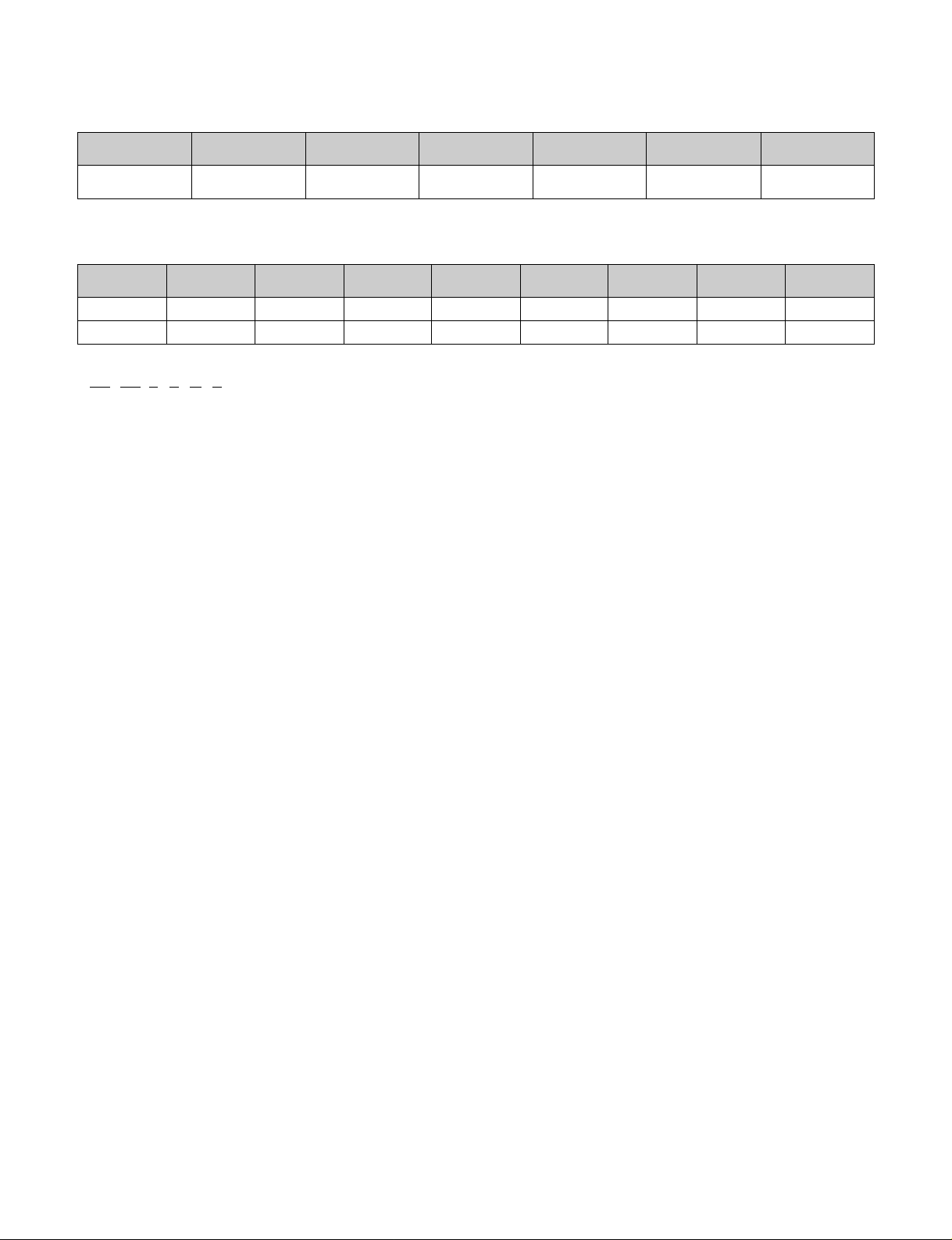
1.1 SPECIFICATIONS
LP120CEM 11800/11500 1055/1025 11.2/11.2 - - 20
Model Name Cooling(Btu/h) Cooling Watts(W) EER
Electric Heat
(Btu/h)
Electric Heat
Amps(A)
Min Circuit
Protection (Amps)
Cooling / Electric Heater
LP090HEM 9300/9000 800/775 11.6/11.6 8200/8000 3.4/3.4 11900/9900 3.2/3.5 20
LP120HEM 12100/11800 1090/1065 11.1/11.1 10900/10700 3.3/3.3 11900/9900 4.4/4.8 20
Model Name Cooling(Btu/h)
Cooling
Watts(W)
EER
Electric Cycle
Heat (Btu/h)
COP
Electric Heat
(Btu/h)
Electric Heat
Amps(A)
Min Circuit
Protection (Amps)
Cooling / Heat Pump / Electric
LP 12 0 C M 2
12 34 5 6 7 8
Digits 1,2 - LG Packaged Terminal Air Conditioner Digit 6 - Product Type
Digits 3,4 - Unit Cooling Capacity C = Air Conditoner
07 = 7,000 Btu/h H = Heat Pump
09 = 9,000 Btu/h Digit 7- Control Type
12 = 12,000 Btu/h M = Mechanical Control
15 = 15,000 Btu/h Digit 8 - Electric Heating Capacity
Digit 5 - Serial No. 2 = 2.0 kW
3 = 3.5 kW
5 = 5.0 kW
Page 4

1.2 features
Unit Features
The PTAC has many features, some of which are different than those found on conventional PTAC units. The servicer must be
familiar with these features in order to
properly service the unit.
• Highly featured Micom controls using IIR (infinite impulse response)
IIR function can make Micom controls maximize and keep the comfort conditions to sense the small changes in temperature
per second.
• Compressor Restart delay
This feature extends the overall life of compressor by preventing the short-cycling of the air-conditioner. When the
compressor restarts, LG PTAC is designed to give a minimum of three minutes to have a time of equalizing the refrigerant
pressures for optimizing cycling.
• Fan-Only Setting - High/Low
The unit provides the function of selecting the either High or Low speed for Fan-Only operation.
• Indoor Fan Speed Selections - High/Low
The unit is operated in High-Heat or Low-Heat or High Cool or Low Cool.
• Two Fan motors
The unit has two fan motors to provide the occupants with the quiet environment to enjoy the peaceful life and maximum
operating efficiency.
• LED Diagnostics
All units have this feature indicating the problem when the unit is not operating properly with easy -to-read diagnostics. For
example, 1 blink every 2 seconds indicates the compressor failure.
• Indoor Filters
The unit uses the two indoor filters easily slide in and out. The filters may be cleaned by washing and brushing without
removing the front grille.
• Rotary Compressor
The unit uses the rotary compressor for the quiet, reliable operation and prolong life.
• 2 Position Discharge Grille
The discharge grille can provide air flows upward at an angle of 40 off vertical or 80 15 degree off vertical. An angle is
changed by removing the front grille and 4screws that fasten the discharge grille to the front grille to rotate an alternate
position of the louvers.
• Indoor Room Freeze Protection
When the unit senses the room temperature falls to 40˚F below, the unit activates the fan motor and either the electric
resistance heater or the hydronic heater to prevent pipes or fixtures from freezing. This also overrides front desk control of the
unit mounted or wall mounted controls.
• Door Switch/Occupancy Sensor
The unit is capable of accommodating a field installed door switch and occupancy sensor to operate the energy management
feature. For additional information, refer to the Unit Operation section.
• Compressor Overload Protection
This feature prevents the damage of the compressor by sensing the indoor tube temperature in heating. If the indoor
temperature is over 130˚F, the outdoor fan will be switched off and on below 120˚F.
—4—
Page 5

• Outdoor Air Temperature Switchover
The unit is designed to control the electric heater interfacing with the outdoor temperature. When the outdoor temperature falls
to 20˚F below, it makes the compressor be off and the electric heater be turned on until the outdoor temperature is above
25˚F. This will effectively change the Unit from heat pump mode to total electric resistance heat.
• Temperature limits
The unit is programmed to provide both heating and cooling temperature limits by dip switches on control panel from 50˚F to
90˚F. Temperature limits help to prevent overheating and overcooling for reducing the energy costs.
• Condensate Drain Valve
The unit has the condensate drain valve that prevents water from freezing in basepan.
• Quick Heater Recovery
The unit is designed to operate the electric heater to warm the room to the temperature set point as soon as heat pump cycle
is on in heating. This feature has an advantage of reducing the time to reach the set point and improving the temperature
increase for better comfort.
• Reverse Cycle Defrosting - (PTHDs only)
The unit will activate the reverse cycle defrost When the outdoor coil temperature has remained at a cold temperature to form
the ice on the coil.This ice will reduce airflow though the coil and will also reduce the efficiency of unit. The LG PTHP will
employ an active reverse cycle defrost function to melt the ice off the outdoor coil for insuring room comfort conditions and
savings from extended operation.
• High Temperature Heat Pump Operation Protection
The compressor will be switched off to prevent damage when the heat pump is operated in high outdoor temperatures.
• Remote Thermostat Control
Each unit is built to be operated from any standard 4 or 5 wire remote-mounted thermostat, if desired. The unit has a built-in
low voltage power source which can accommodate a large variety of thermostat choices-manual, auto changeover or
programmable. A remote thermostat can also be added to any installed unit.
• Zone Sensor
Occupants enjoy ultimate comfort with consistent climate control. Attach an optional, inexpensive remote Zone Sensor, to
exactly match the functions of the PTAC without disabling any features.
—5—
Page 6
—6—
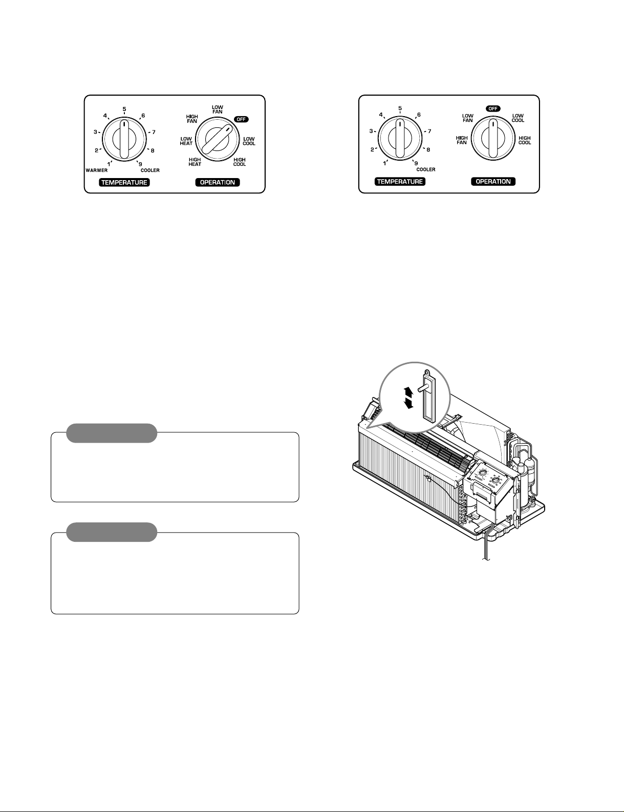
1.3 CONTROL LOCATIONS
• OPERATION
ELECTRIC HEATING MODEL COOLING ONLY MODEL
VENT
CLOSE
VENT
OPEN
TEMPERATURE CONTROL
Set the Thermostat control to the desired temperature
mark 5 (the mid-point is a good starting position). If the
room temperature is not satisfactory after a reasonable
time, adjust the control to a cooler or warmer setting, as
appropriate.
OPERATION MODE SELECTOR
OFF: Turns air conditioner off.
LOW FAN: Low speed fan operation without cooling.
HIGH FAN: High speed fan operation without cooling.
LOW COOL: Cooling with the low speed fan operation.
HIGH COOL: Cooling with the high speed fan operation.
LOW HEAT: Heating with the low speed fan operation.
HIGH HEAT: Heating with the high speed fan operation.
• VENTILATION
The ventilation lever is located to the lower left side of the unit.
The ventilation lever must be in the CLOSE position in order
to maintain the best cooling conditions.
When fresh air is necessary in the room, set the ventilation
lever to the OPEN position.
The damper is opened and outdoor air is drawn into the room.
This will reduce the cooling or heating efficiency.
When the air conditioner has performed a cooling or
heating operation and is turned off or set to the fan
position, wait at least 3 minutes before resetting to the
cooling operation.
A slight heat odor may come from the unit when first
switching to HEAT after the cooling season is over.
This odor, caused by fine dust particles on the heater, will
disappear quickly.
This is harmless.
CAUTION
NOTE
Page 7
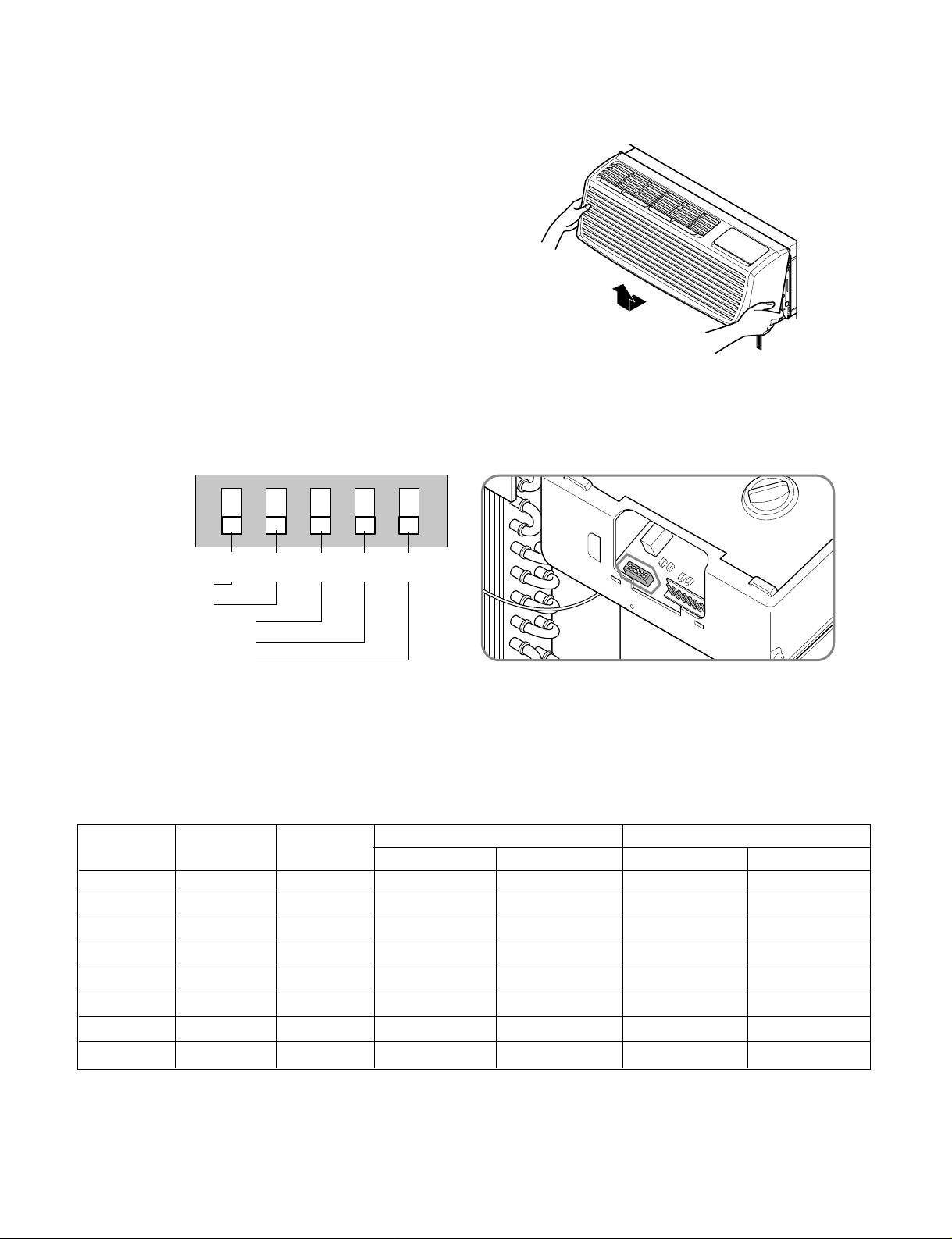
1.4 ADDITIONAL CONTROLS
• REMOVING THE FRONT GRILLE
Additional controls are available after removing the front
grille and option cover of control box.
To remove the front grille, pull out the bottom of front
grille and then lift up.
To replace the front grille, place the tabs over the top of
the unit and push the bottom of front grille until the clips
snap into place.
• ADDITIONAL CONTROLS
The additional controls are located behind the option cover of control box. The standard settings will be in the OFF position.
The authorized service man has to check switches and ensure the switches are in the desired position.
• TEMPERATURE LIMITING
Temperature Limiting can save money by limiting the lowest temperature for cooling and the highest temperature for heating.
The temperature limiting is controlled by dip switch #1 - #3.
This temperature limiting is not available with the Remote Wall Thermostat.
—7—
ON
ONREMOTE
OFF
ON ON ON
Remote/Local
Energy Saver
Temperature Limit 1
Temperature Limit 2
Temperature Limit 3
LOCALLOCAL
1
OFF
OFF
2
OFF
OFF
3
OFF
OFF
4
OFF
OFF
5
LOCAL
1
OFF2OFF3OFF4OFF
5
LOCALLOCAL
1
OFF
OFF
2
OFF
OFF
3
OFF
OFF
4
OFF
OFF
5
LOCAL
1
OFF2OFF3OFF4OFF
5
Temperature Temperature Temperature
Limit #1 Limit #2 Limit #3
OFF OFF OFF 54°F (12.2°C) 86°F (30.0°C)
ON OFF OFF 56°F (13.3°C)
OFF ON OFF 58°F (14.4°C)
ON ON OFF 60°F (15.5°C)
OFF
ON OFF ON 64°F (17.7°C)
OFF ON ON 66°F (18.9°C) 74°F (23.3°C)
ON ON ON 68°F (20.0°C) 72°F (22.2°C)
OFF ON 62°F (16.6°C)
Cooling Operation
Heating Operation
Lowest Temp. Highest Temp. Lowest Temp. Highest Temp.
86°F (30.0°C)
86°F (30.0°C)
86°F (30.0°C)
86°F (30.0°C)
86°F (30.0°C)
86°F (30.0°C)
86°F (30.0°C)
54°F (12.2°C)
54°F (12.2°C)
54°F (12.2°C)
54°F (12.2°C)
54°F (12.2°C)
54°F (12.2°C)
54°F (12.2°C)
54°F (12.2°C)
86°F (30.0°C)
84°F (28.9°C)
82°F (27.8°C)
80°F (26.7°C)
78°F (25.5°C)
76°F (24.4°C)
Page 8
• REMOTE/LOCAL CONTROL
When remote/local switch #1 is on, it allow the unit to operate by the control of Remote Wall Thermostat.
The unit control by knobs are not available.
• ENERGY SAVER
The energy saver switch #2 is on. This switch is set at continuous fan to provide continuous fan operation in cool or heat
modes. When the switch is off the continuous fan allows continuous circulation of room air and make the more balanced
temperature of the room. When the switch is on the fan is on or off with the compressor or with the heater.
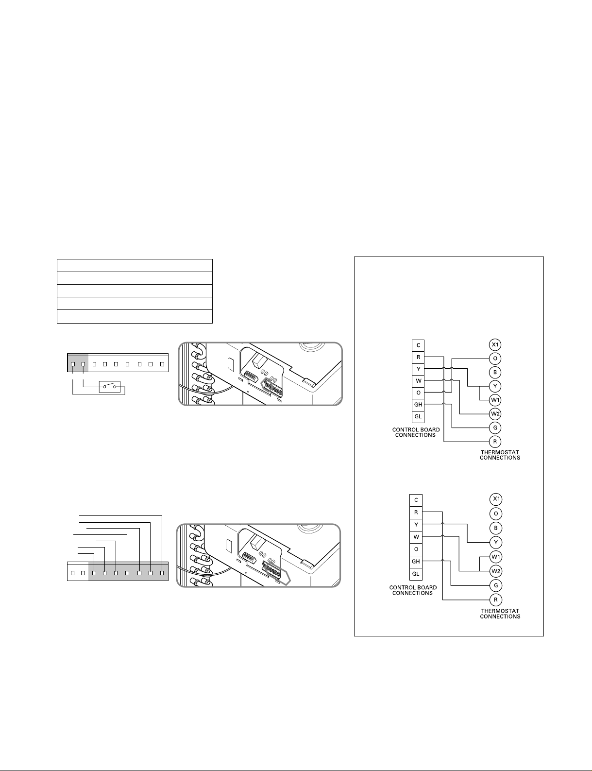
• FRONT DESK CONTROL
When the pair wire is connected to the connector LOand LI, the unit can be turned ON or OFF with a switch located at the
Front Desk Control panel. When the front desk switch is ON, the fan operate according to the condition of setting without
working compressor and heater. When the front desk switch is OFF, the unit can operate according to the setting of controls.
• REMOTE WALL THERMOSTAT
When the wires are connected, the unit will be controlled by a remote wall
thermostat.
The thermostat connections supply the 24 Volt AC. When you install the
digital / electronic thermostat, you must set it to the 24 Volt AC. See the
installation Instruction in this manual for the Remote Wall Thermostat.
—8—
GL GH O W Y R CLO LI
Front Desk Switch
LO LI GL GH O W Y R C
Low Fan
High Fan
Reversing V alve
Heater
Compressor
24 Volt-L
24 Volt-N
Wiring Schematic for
Remote Heat Pump
Wiring Schematic for
Straight Cool Unit.
Note: The following figures show wiring
schematics for heat pump and straight cool
units with electric heat, respectively.
Wire # AWG Maximum Length
#22
600ft(180m)
#20 900ft(270m)
#18 1500ft(450m)
#16 2000ft(610m)
Page 9
—9—
2.1 MECHANICAL PARTS
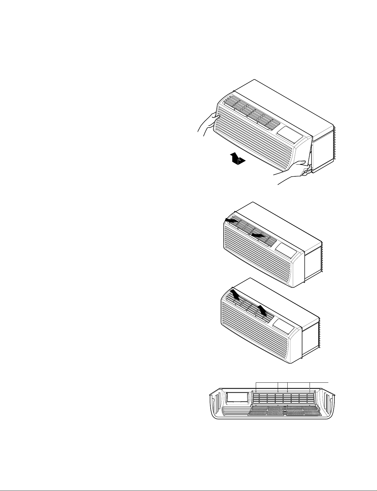
2.1.1 FRONT GRILLE
1. Remove the front grille. (See Fig. 1)
2. To remove the front grille, pull out the bottom of
the front grille and then lift up.
Re-install the component by referring to the
removal procedure.
3. To replace the front grille, place the tabs over the
top of the unit and push the bottom of front grille
until the clips snap into place.
• This Room Air Conditioner (PTAC) discharges air
from the top of the unit through reversible, 2-position
discharge grille louvers. The unit is shipped from the
factory with the discharge grille louvers at an angle
of 40˚ off vertical. In an alternate position the louvers
will be at an angle of 15˚ off vertical.
To adjust air direction, remove the front grille.
Remove the 4 screws that fasten the discharge grille
to the front grille.
Flip the discharge grille 180°, then reattach the
discharge grille to the front grille with 4 screws.
2. DISASSEMBLY INSTRUCTIONS
— Before the following disassembly, POWER SWITCH is set to OFF and disconnected the power cord.
Figure 1
40˚
15˚
Screws
Page 10
—10—
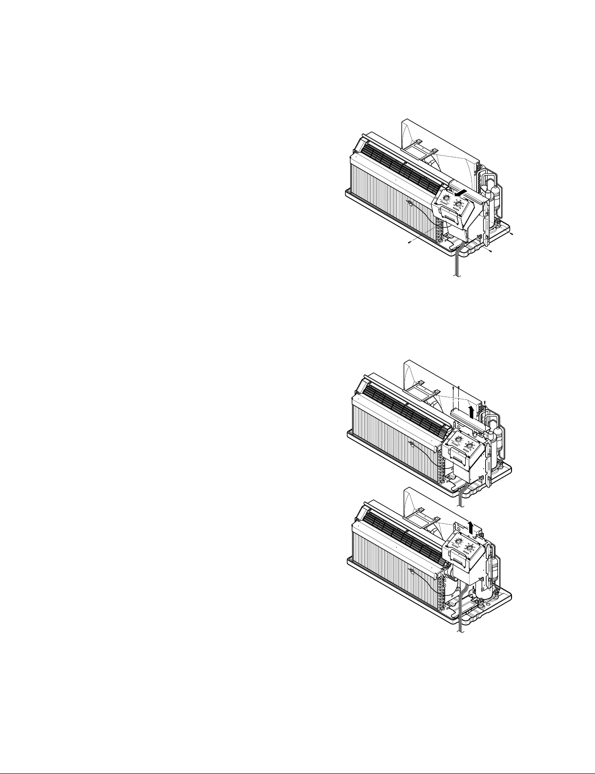
2.1.2 CONTROL BOX (Half-Disassembly)
1. Remove the front grille. (Refer to section 2.1.1)
2. Remove the three screw which fasten the control
box. (See Fig. 2)
3. Pull the control box from the barrier. (See Fig.2)
4. Discharge the capacitor by placing a 20,000 ohm
resistor across the capacitor terminals.
5. Disconnect three wire housings in the control box.
6. Pull the control box forward completely.
7. Re-install the components by referring to the
removal procedure. (See Fig. 2)
(Refer to the circuit diagram found on page 25 in
this manual and on the control box.)
2.1.3 CONTROL BOX (Full-Disassembly)
1. Remove the front grille. (Refer to section 2.1.1)
2. Remove the 4 screws which fasten the control box
cover. (See Fig.3)
3. Disconnect three wire housings in the control box.
4. Remove three screws which fasten the control box
assembly.
5. Pull the control box assembly out from the unit.
Figure 2
Figure 3
Page 11
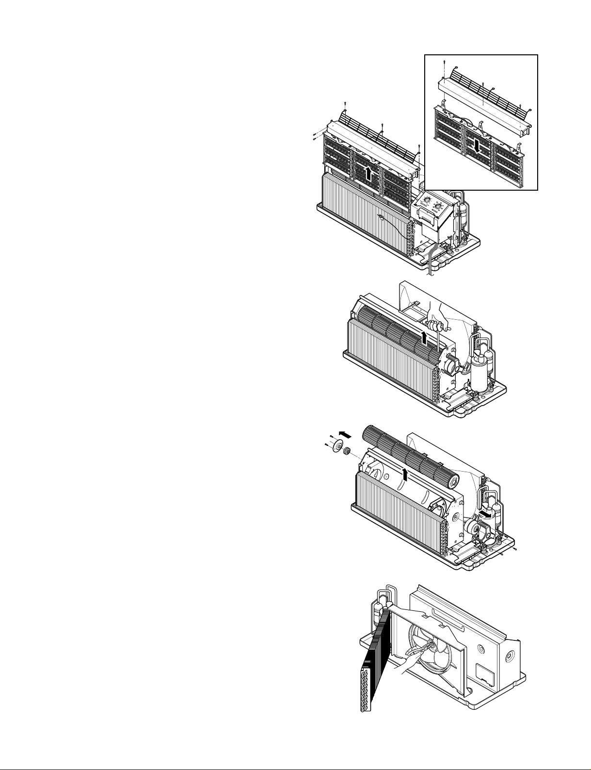
Figure 7
—11—
2.2 AIR HANDLING PARTS
2.2.1 HEATER ASSEMBLY AND CROSS
FLOW FAN
1. Remove the front grille. (Refer to section 2.1.1)
2. Remove the control box assembly.
(Refer to section 2.1.3)
3. Remove the 3 screws which fasten the net steel.
(See Fig. 4)
4. Remove the 3 screws which fasten the electric
heater assembly. (Electric heater model only)
(See Fig.4).
5. Loosen the hexagon screw with the Hex-wrench
(See Fig.5)
6. Remove the 4 screws which fasten the indoor
motor and the earth wire. (See Fig. 5. 6)
7. Re-install the components by referring to the
removal procedure, above.
2.2.2 FAN
1. Remove the brace.
2. Remove the 4 screws which fasten the condenser
with the shroud and the basepan.
3. Move the condenser sideways carefully.
4. Remove the clamp which secures the fan with
pliers.
5. Remove the fan. (See Fig. 7)
6. Re-install the components by referring to the
removal procedure, above.
Figure 4
Figure 5
Figure 6
Page 12

—12—
2.2.3 SHROUD
1. Remove the fan. (Refer to section 2.2.2)
2. Remove the screw which fastens the shroud.
3. Remove the shroud. (See Fig. 8)
4. Re-install the component by referring to the
removal procedure, above.
2.3 ELECTRICAL PARTS
2.3.1 OUTDOOR MOTOR
1. Remove the clamp cord and disconnect a wire
housing in control box. (Refer to section 2.1.2)
2. Remove the fan. (Refer to section 2.2.2)
3. Remove the 2 screws which fasten the motor.
(See Fig. 9)
4. Remove the motor.
5. Re-install the components by referring to the
removal procedure, above.
2.3.2 INDOOR MOTOR (Refer to section 2.2.1)
2.3.3 COMPRESSOR
1. Discharge the refrigerant system using Freon
TM
Recovery System.
If there is no valve to attach the recovery system,
install one (such as a WATCO A-1) before venting
the Freon
TM
. Leave the valve in place after
servicing the system.
2. Disconnect the 3 leads from the compressor.
3. After purging the unit completely, unbraze the
suction and discharge tubes at the compressor
connections.
4. Remove the 3 nuts and the 3 washers which
fasten the compressor. (See Fig. 10)
5. Remove the compressor.
6. Re-instill the components by referring to the
removal procedure, above.
2.3.4 CAPACITOR
1. Remove the control box. (Refer to section 2.1.2)
2. Remove 1 screw and disconnect the leads which
connected to the box type capacitor.
(See Fig. 11)
3. Remove 1 screw and the clamp which fastens the
can-type capacitor. (See Fig. 11)
4. Disconnect all the leads of capacitor terminals.
5. Re-install the components by referring to the
removal procedure, above.
Figure 8
Figure 9
Figure 10
Figure 11
Page 13

—13—
2.3.5 POWER CORD
1. Remove the control box. (Refer to section 2.1.2)
2. Disconnect the grounding screw from the control
box.
3. Disconnect 2 receptacles.
4. Remove a screw which fastens the clip cord.
5. Separate the power cord from the control box.
(See Fig. 12)
6. Re-install the component by referring to the
removal procedure, above.
(Use only one ground-marked hole for ground
connection.)
7. If the supply cord of this appliance is damaged, it
must be replaced by the special cord.
(The special cord means the cord which has the
same specification marked on the supply cord
fitted to the unit.)
2.3.6 P.C.B.
1. Remove the escutcheon.
2. Remove the two knobs.
3. Remove the 2 screws which fasten P.C.B. cover.
4. Disconnect all the leads which connected to the
P.C.B.
5. Remove the two screws which fasten the P.C.B.
board.
6. Re-install the components by referring to the
removal procedure, above.
Figure 12
Figure 13
Page 14

—14—
2.4 REFRIGERATION CYCLE
2.4.1 CONDENSER
1. Remove the brace and the shroud.
(Refer to section 2.2.2)
2. Remove the 4 screws which fasten the shroud.
(Refer to section 2.2.2)
3. Push forward the shroud and remove the 2 screws
which fasten the condenser with the basepan.
4. After discharging the refrigerant completely,
unbraze the interconnecting tube at the condenser
connections.
5. Remove the condenser.
6. Re-install the components by referring to notes.
(See Fig. 14)
2.4.2 EVAPORATOR
1. Remove the front grille. (Refer to section 2.1.1)
2. Discharge the refrigerant completely.
3. Remove the control box assembly.
(Refer to section 2.1.2)
4. Remove the 4 screws which fasten the evaporator
at the left side and the right side.
5. Move the evaporator sideward carefully and then
unbraze the interconnecting tube at the evaporator
connectors.
6. Remove the evaporator.
7. Re-install the components by referring to notes.
(See Fig. 15)
2.4.3 CAPILLARY TUBE
1. After discharging the refrigerant completely,
unbraze the interconnecting tube at the capillary
tube.
2. Remove the capillary tube.
3. Re-install the components by referring to notes.
Figure 14
Figure 15
Discharge the refrigerant system using Freon
TM
Recovery System.
If there is no valve to attach the recovery system,
install one (such as a WATCO A-1) before
venting the Freon
TM
. Leave the valve in place
after servicing the system.
CAUTION
Figure 15
Page 15

—15—
— Replacement of the refrigeration cycle.
1. When replacing the refrigeration cycle, be sure to
discharge the refrigerant system using a Freon
TM
recovery System.
If there is no valve to attach the recovery system,
install one (such as a WATCO A-1) before venting
the FreonTM. Leave the valve in place after
servicing the system.
2. After discharging the unit completely, remove the
desired component, and unbraze the pinch-off
tubes.
3. Solder service valves into the pinch-off tube ports,
leaving the valves open.
4. Solder the pinch-off tubes with Service valves.
5. Evacuate as follows.
1) Connect the vacuum pump, as illustrated Fig.
16A.
2) Start the vacuum pump, slowly open manifold
valves A and B with two full turns
counterclockwise and leave the valves closed.
The vacuum pump is now pulling through valves
A and B up to valve C by means of the manifold
and entire system.
3) Operate the vacuum pump for 20 to 30 minutes,
until 600 microns of vacuum is obtained. Close
valves A and B, and observe vacuum gauge for
a few minutes. A rise in pressure would
indicate a possible leak or moisture remaining in
the system. With valves A and B closed, stop
the vacuum pump.
4) Remove the hose from the vacuum pump and
place it on the charging cylinder. See Fig. 16B.
Open valve C.
Discharge the line at the manifold connection.
5) The system is now ready for final charging.
6. Recharge as follows :
1) Refrigeration cycle systems are charged from the
High-side. If the total charge cannot be put
in the High-side, the balance will be put in the
suction line through the access valve which you
installed as the system was opened.
2)
Connect the charging cylinder as shown in Fig. 16B.
With valve C open, discharge the hose at the
manifold connection.
3) Open valve A and allow the proper charge to
enter the system. Valve B is still closed.
4) If more charge is required, the high-side will not
take it. Close valve A.
5) With the unit running, open valve B and add the
balance of the charge.
a. Do not add the liquid refrigerant to the Low-
side.
b. Watch the Low-side gauge; allow pressure to
rise to 30 lbs.
c. Turn off valve B and allow pressure to drop.
d. Repeat steps B and C until the balance of the
charge is in the system.
6) When satisfied the unit is operating correctly,
use the pinch-off tool with the unit still running
and clamp on to the pinch-off tube. Using a tube
cutter, cut the pinch-off tube about 2 inches from
the pinch-off tool. Use sil-fos solder and solder
pinch-off tube closed. Turn off the unit, allow it to
set for a while, and then test the leakage of the
pinch-off connection.
NOTES
If high vacuum equipment is used, just crack
valves A and B for a few minutes, then open
slowly with the two full turns counterclockwise.
This will keep oil from foaming and being
drawn into the vacuum pump.
CAUTION
Page 16

—16—
Equipment needed: Vacuum pump, Charging cylinder, Manifold gauge, Brazing equipment. Pinch-off tool
capable of making a vapor-proof seal, Leak detector, Tubing cutter, Hand Tools to remove components, Service
valve.
A
COMPOUND GAUGE
EVAPORATOR
(LOW PRESSURE SIDE)
COMPRESSOR
CAPILLARY TUBE
CONDENSER
(HIGH PRESSURE SIDE)
SEE INSETS
BELOW
MANIFOLD
GAUGE
B
Figure 16A-Pulling Vacuum
Figure 16B-Charging
A
B
EXTERNAL
VACUUM PUMP
LOW
B
HI
A
CHARGING
CYLINDER
C
Page 17

—17—
3. INSTALLATION
3.1 HOW TO INSTALL THE UNIT
For existing sleeve, you should measure the wall sleeve
dimensions.
You can install the new air conditioner according to these
installation instructions to achieve the best performence. All
wall sleeves used to mount the new air conditioner must be in
good structural condition and have the rear grille that securely
attaches to the sleeve or the flange of the sleeve to secure the
new air conditioner.
• To avoid vibration and noise, make sure the unit is installed
securely and firmly.
A. BEFORE ATTACHING THE FRONT
GRILLE TO THE SLEEVE, IF YOU WANT
TO PULL OUT THE FILTER UPWARD;
1. There should be no obstacle, like a fence, within 20" which
might restrict heat radiation from the condenser.
B. IF YOU WANT TO PULL OUT THE FILTER
DOWNWARD;
The grille is already designed for that way.
1. Install the unit a little obliquely outward not to leak the
condensed water into the room (about 1/2" or 1/4" bubble
with level).
2. Install the unit with its bottom portion 30~60" above the floor
level.
3. The power cord must be connected to an independent
circuit. The green wire must be grounded.
406mm
(16")
406mm
(16")
1,066mm(42")
1066mm
(42")
318mm
(12 1/2")
318mm
(12 1/2")
505mm
(20")
Over 20"
HEAT
RADIATION
WALL
WALL
INSULATION SLEEVE
INTAKE
AIR
COOLED
AIR
Level
1/4" Bubble
1/4" Bubble
of the level
• There are sharp edges that can cause serious cuts.
• When lifting the air conditioner, it is HEAVY.
Use 2 peoples to lift.
CAUTION
Dimension of air conditioner
Dimension of sleeve assembly (optional)
Page 18

—18—
3.2.1 PREPARATION OF SLEEVE
ASSEMBLE THE WALL SLEEVE
• Raise the sleeve side panels to upright position as shown on
the right.
• Place sleeve upper on top of side panels.
• Fasten the four screws as shown on the right.
• Assemble drain kit.
• Fasten this assembly to the each side of the wall sleeve as
shown on the right.
• Assemble the outdoor grille and fasten the 4 screws as
shown on the right.
3.2.2 PREPARATION OF THE FRONT GRILLE
Carefully remove shipping tape, if there is any, from the front
grille.
SCREWDRIVER(+, -), RULER, KNIFE, HAMMER, PENCIL, LEVEL
INDOOR
3.2 SUGGESTED TOOL REQUIREMENTS
SLEEVE HARDWARE
NUMBER NAME OF PARTS Q’TY
SLEEVE LOWER 1
SLEEVE UPPER 1
SCREW 4
OUTDOOR GRILLE 1
DRAIN KIT 1
12
14
R
O
O
D
N
11
I
R
O
O
D
N
I
R
O
O
D
IN
I
N
D
O
O
R
R
O
O
D
N
I
Shipping tape
Page 19

—19—
3.2.3 UNIT INSTALLATION
1. Remove the shipping screw from the ventilation door.
(See Fig. 17)
2. Remove the front gille by pulling it out at the bottom to
release it, then lift it up along the unit top front.
(See Fig. 18)
3. Slide the unit into the wall sleeve and secure with 6 screws
through the unit flange holes. (See Fig. 19)
4. Reinstall the front grille by hooking the top over the unit top,
then pushing it in at the bottom. (See Fig. 20)
Figure 17
Figure 18
Figure 19
Figure 20
Page 20

—20—
Perpendicular
20 A
Tandem
15 A
Large T andem
30 A
230/208 volt receptacle configuration
CAUTION
1. Do not use an extension cord with this unit.
2. When the unit is in the OFF position, the power supply to the
electrical controls.
3. Disconnect the power to the unit before servicing
the unit.
4. Remove the power cord from the wall receptacle.
5. Remove or turn off the protective device (fuses or circuit breaker).
Wirings including installation of the receptacle must comply with the
NEC and local codes, local regulations.
FUSE- Use a time-delay fuse or circuit breaker. Refer to the nameplate
for proper power supply requirements.
3.3.1 ELECTRICAL DATA (FOR 230/208V MODEL)
3.3.2 ELECTRICAL SAFETY
IMPORTANT GROUNDING INSTRUCTIONS
Air conditioner has a three-prong grounding plug on its power supply cord, which must be plugged into properly grounded
three-prong wall receptacle for your protection against possible shock hazard.
FUSE – Use a time-delay fuse or circuit breaker. Refer to the nameplate for proper power supply requirements.
208, 230, and 208/230 VOLT UNITS
These units are equipped with a three-prong grounding plug on the power supply cord, which must be plugged into a matching
properly grounded three-prong wall receptacle for your protection against possible shock hazard. If such an outlet is not
present, one must be installed by a qualified electrician in accordance with the National Electrical Code and local codes and
ordinances.
NOTE: DO NOT USE AN EXTENSION CORD on 208, 230, and 208/230 Volt units.
3.3 ELECTRICAL REQUIREMENTS
Page 21

4. PERFORMANCE DATA
—21—
Voltage (V)
Cooling Data
Cooling Capacity
(Btu/h)
Cooling Amps (A)
Cooling Power (W)
EER (Btuh/Watt)
Moisture Removal
(Pts/h)
Airflow
Indoor CFM (Wet)
@0.3ESP (Hi)
Indoor CFM (W
et)
@0.3ESP (Lo)
Indoor CFM (Dry)
@0.3ESP (Hi)
Indoor CFM (Dry)
@0.3ESP (Lo)
208 230
11,500
4.8
1025
11.0
LP120CEM
208 230
11,800
5.2
1055
11.0
Voltage (V)
Cooling Data
Cooling Capacity (Btu/h)
Cooling Amps (A)
Cooling Power (W)
EER (Btuh/Watt)
Moisture Removal (Pts/h)
Heat Pump Heating Data
Heating Capacity (Btu/h)
Heating Amps (A)
Heating Power (W)
COP (W/W)
Airflow
Indoor CFM (W
et)
@0.3ESP (Hi)
Indoor CFM (W
et)
@0.3ESP (Lo)
Indoor CFM (Dry)
@0.3ESP (Hi)
Indoor CFM (Dry)
@0.3ESP (Lo)
LP090HEM
208 230
9,000 9,300
3.9 3.7
775 800
11.6 11.6
3.4 3.4
8,000 8,200
3.5 3.2
690 705
LP120HEM
208 230
4.8
950
208 230
3.3
970
Air Conditioner Performance Data
Heat Pump Performance Data
11,800
5.4
12,100
5.0
1,065
11.1
1,090
11.1
3.3
10,700 10,900
4.4
3.3
240
190
260
220
3.3
270
230
290
250
3.3
330
290
350
310
3.3
300
290
320
280
3.4
310
270
330
290
3.4
340
300
360
330
Page 22

—22—
Model LP120CEM
T emperature
Outdoor
Air Return Air Total Wattage
Dry Bulb Wet Bulb
Input
Min Max
Rating Wattage 1045 1090
85 1050 1180
80 1055 1180
75 1060 1180
100 70 1055 1180
65 1050 1180
60 1045 1175
55 1030 1160
85 1000 1125
80 1005 1130
75 1005 1135
95 70 1005 1130
65 1000 1125
60 990 1120
55 980 1105
85 950 1070
80 950 1075
75 955 1080
90 70 950 1075
65 950 1070
60 940 1060
55 930 1055
85 895 1020
80 900 1020
75 905 1030
85 70 900 1020
65 895 1020
60 890 1010
55 880 1000
85 850 970
80 850 970
75 850 975
80 70 850 970
65 850 970
60 940 960
55 830
950
Cooling Wattage - Air Conditioners
Page 23

—23—
Model LP090HM* LP120HEM
T emperature
Outdoor
Air Return Air T otal W attage Total Wattage
Dry Bulb Wet Bulb Input
Input
Min Max Min Max
Rating Wattage 810 850 1120
1145
85 830 935 1120 1230
80 835 940 1125 1235
75 835 940 1130 1240
100 70 835 940 1125 1240
65 830 935 1120 1230
60 820 925 1115 1230
55 810 915 1100 1210
85 785 890 1070 1180
80 790 890 1075 1190
75 795 890 1075 1190
95 70 790 890 1075 1190
65 785 890 1070 1180
60 780 880 1060 1170
55 770 865 1050 1160
85 745 845 1020 1130
80 750 850 1025 1135
75 750 850 1025 1135
90 70 750 850 1025 1125
65 745 845 1020 1130
60 735 835 1010 1120
55 720 825 1000 1110
85 700 800 970 1080
80 705 800 975 1085
75 705 810 975 1085
85 70 705 800 975 1085
65 700 800 970 1080
60 690 790 960 1070
55 680 775 950 1060
85 655 755 920 1030
80 660 760 925 1030
75 660 760 925 1035
80 70 660 760 920 1030
65 655 755 920 1030
60 650 745 910 1020
55 635 735 900
1010
Cooling Wattage - Heat Pumps
Page 24

—24—
Cooling change of temperature - Air Conditioners
Room Air Room Air LP120CEM
Dry Wet T
emperature Across
Bulb Bulb
Indoor Coil (∆ T)
Min Max
Rating Btu/h 11700
12000
Rating CFM 300 330
85 1 5
80 9 13
90 75 18 22
70 26 30
80 5 10
75 13 18
85 70 21 25
65 29 33
75 9 13
70 15 20
80 65 23 26
60 29 33
70 10 15
65 15 20
75 60 21 25
55 26 30
65 9 13
70 60 13
17
55 18
21
Model
Room Air Room Air LP090HEM LP120HEM
Dr y Wet Temperature Across T
emperature Across
Bulb Bulb Indoor Coil (∆ T) Indoor Coil (∆
T)
Min Max Min Max
Rating Btu/h 9300 9600 12300
12600
Rating CFM 240 270 310 340
85 2 6 1 5
80 11 15 10 13
90 75 19 22 18 22
70 29 30 26 30
80 7 11 5 10
75 15 18 14 18
85 70 23 25 21 25
65 31 33 30 33
75 11 15 10 13
70 18 20 16 20
80 65 24 27 23 26
60 32 33 30 33
70 13 16 11 15
65 18 21 16 20
75 60 23 26 21 25
55 29 31 26 30
65 12 15 10 13
70 60 16 18 14
17
55 20 22 18
21
Cooling Change of Temperature - Heat Pumps
Page 25

—25—
Cooling Ampere Chart - Air Conditioners
Cond Inlet Air
Te
mperature
Rating Ampere
100
95
90
85
80
LP120CEM
Model
Amperage
Min Max
4.8 5.2
5.6 5.6
5.4 5.3
5.2 5.1
4.9 4.8
4.7 4.6
Model
Room Air Room Air LP090HEM LP120HEM
Dry Wet T emperature Across Temperature Across
Bulb Bulb Indoor Coil (∆ T)
Indoor Coil (∆ T)
Min Max Min Max
Rating Btu/h 8200 8400 10900 11200
Rating CFM 260 290 330 360
85 24 27 27 30
80 25 28 28 31
50 75 26 29 29 32
70 28 30 31 34
65 28 30 31 34
85 22 24 24 29
80 23 25 25 29
45 75 24 26 26 30
70 24 27 27 31
65 25 28 28 32
85 20 22 23 27
80 21 23 23 28
40 75 22 24 24 29
70 23 24 25 29
65 24 25 26 30
85 17 20 21 24
80 18 21 22 25
35 75 19 22 23 26
70 20 23 23 27
65 21 24 24
28
Heating Change of Temperature - Heat Pumps
Cond Inlet Air
Te
mperature
Rating Ampere
10
0
95
90
85
80
LP090HM* LP120HEM
Model
Amperage
Min Max
3.6 3.9
3.4 4.0
3.2 3.8
3.1 3.6
3.1 3.4
2.9 3.3
Model
Amperage
Min Max
4.8 5.2
5.6 5.5
5.3 5.2
5.0 5.0
4.8 4.7
4.6 4.5
Cooling Ampere Chart - Heat Pumps
Page 26

—26—
5. TROUBLESHOOTING GUIDE
5.1 OUTSIDE DIMENSIONS
1,066mm(42")
505mm(20")
406mm(16")
406mm(16")
5.2 PIPING SYSTEM
Following is a brief description of the important components and their functions in the refrigeration system.
Refer to Fig. 21 to follow the refrigeration cycle and the flow of the refrigerant in the cooling cycle.
MOTOR
COMPRESSOR
OIL
(LIQUID REFRIGERANT)
CAPILLARY TUBE
OUTSIDE COOLING
AIR FOR REFRIGERANT
PASS THROUGH
SUCTION LIME
COOL LOW PRESSURE VAPOR
COOLED
AIR
COMPLETE LIQUID
BOIL OFF POINT
LIQUID
PRESSURE
DROP
ROOM AIR HEAT LOAD
VAPOR INLET
HOT
DISCHARGED
AIR
LIQUID OUTLET
HIGH PRESSURE VAPOR
LIQUID PEFRIGERANT
LOW PRESSURE VAPOR
ROOM AIR CONDITIONER
EVAPORATOR COILS CONDENSER COILS
CYCLE OF REFRIGERATION
Figure 21
Page 27

—27—
5.3 TROUBLESHOOTING GUIDE
In general, possible trouble is classified in two causes.
The one is called Starting Failure which is caused from an electrical defect, and the other is Ineffective Air
Conditioning caused by a defect in the refrigeration circuit and improper application.
Unit is running but cooling is ineffective
Ineffective Cooling
Check of outdoor coil
(heat exchanger) & the fan
operation.
Check gas leakage.
Repair gas leak.
Replacement of unit if the
unit is beyond repair.
Satisfactory operation with
temperature difference of
inlet & outlet air ; 44.6~50˚F
Check heat load increase.
Unexpected residue
Overloaded Circuit
Check of inside gas
pressure.
Adjusting of refrigerant
charge
Malfunction of compressor
Replacement of
compressor
Check of cold air circulation
for smooth flow.
Dirty indoor coil
(Heat exchanger)
Malfunction of fan
Clogged of air filter
Obstruction at air outlet
Correct above trouble
Check clogging in
refrigeration circuit.
Repair clogging in
refrigeration circuit.
Page 28

—28—
Fails to Start
Check of circuit breaker
and fuse.
Gas leakage of feeler bulb
of thermostat
Check of control switch.
Only fan fails to start.
Improper wiring.
Defect of fan motor
capacitor.
Irregular motor resistance
( ).
Irregular motor insulation
( ).
Replacement of fan motor
Regular but fails to start
Replacement of compressor
(locking of rotor, metal)
Improper thermostat setting
Loose terminal connection.
Improper wiring
Irregular motor resistance ( )
Irregular motor insulation ( )
Replacement of compressor
(Motor damaged)
Drop of power voltage.
Check capacitor.
Replacement.
Only compressor fails to
start.
Defect of compressor
capacitor.
Check of power source.
Check of control switch
setting.
Page 29

—29——29—
COMPLAINT CAUSE REMEDY
Check voltage at outlet. Correct if none.
Check voltage to rotary switch. If none, check
power supply cord. Replace cord if circuit is open.
Check switch continuity. Refer to wiring diagram
for terminal identification. Replace switch if
defective.
Connect wire. Refer to wiring diagram for terminal
identification. Repair or replace loose terminal.
Test capacitor.
Replace if not within ±10% of manufacturer's
rating. Replace if shorted, open, or damaged.
Fan blade hitting shroud or cross flow fan hitting
scroll. Realign assembly.
Units using slinger ring condenser fans must
have 1/4to 5/16inch clearance to the base. If it is
hitting the base, shim up the bottom of the fan
motor with mounting screw(s).
Check fan motor bearings; if motor shaft will not
rotate, replace the motor.
Check voltage. See limits on this page. If not within
limits, call an electrician.
Test capacitor.
Check bearings. Does the fan blade rotate freely?
If not, replace fan motor.
Pay attention to any change from high speed to
low speed. If the speed does not change, replace
the motor.
Check grommets; if worn or missing, replace them.
If cracked, out of balance, or partially missing,
replace it.
If cracked, out of balance, or partially missing,
replace it.
Tighten it.
If knocking sounds continue when running or
loose, replace the motor. If the motor hums or
noise appears to be internal while running,
replace motor.
No power
Power supply cord
Rotary switch
Wire disconnected or
connection loose
Capacitor (Discharge
capacitor before testing.)
Will not rotate
Revolves on overload.
Grommets
Fan
Turbo fan
Loose set screw
Worn bearings
Fan motor will not run.
Fan motor runs
intermittently
Fan motor noise.
Page 30

—30—
NAME PLATE RATING MINIMUM MAXIMUM
208/230V 187V 253V
COMPLAINT CAUSE REMEDY
Check voltage. See the limits on the preceding.
page. If not within limits, call an electrician.
Check the wire connections, if loose, repair or
replace the terminal. If wires are off, refer to wiring
diagram for identification, and replace. Check wire
locations. If not per wiring diagram, correct.
Check for continuity, refer to the wiring diagram
for terminal identification. Replace the switch if
circuit is open.
Check the position of knob If not at the coldest
setting, advance the knob to this setting and
restart unit.
Check continuity of the thermostat. Replace
thermostat if circuit is open.
Check the capacitor.
Replace if not within ±10% of manufacturers
rating. Replace if shorted, open, or damaged.
Check the compressor for open circuit or
ground. If open or grounded, replace the
compressor.
Check the compressor overload, if externally
mounted. Replace if open. (If the compressor
temperature is high, remove the overload, cool it,
and retest.)
Voltage
Wiring
Rotary
Thermostat
Capacitor (Discharge
capacitor before
servicing.)
Compressor
Overload
Compressor will not run,
but fan motor runs.
ROOM AIR CONDITIONER VOLTAGE LIMITS
Page 31

—31—
COMPLAINT CAUSE
REMEDY
Check the voltage. See the limits on the preceding page. If not within limits, call an electrician.
Check overload, if externally mounted.
Replace if open. (If the compressor temperature
is high, remove the overload, cool, and retest.)
If not running, determine the cause. Replace if
required.
Remove the cabinet. inspect the interior surface
of the condenser; if restricted, clean carefully
with a vacuum cleaner (do not damage fins) or
brush. Clean the interior base before
reassembling.
If condenser fins are closed over a large area
on the coil surface, head pressures will increase,
causing the compressor to cycle. Straighten the
fins or replace the coil.
Test capacitor.
Check the terminals. If loose, repair or replace.
Check the system for a restriction.
If restricted, clean of replace.
Close if open.
Determine if the unit is properly sized for the area to
be cooled.
Check the set screw or clamp. If loose or missing,
correct. If the blower or fan is hitting air guide,
rearrange the air handling parts.
Carefully rearrange tubing not to contact,
compressor, shroud, and barrier.
Voltage
Overload
Fan motor
Condenser air flow
restriction
Condenser fins
(damaged)
Capacitor
Wiring
Refrigerating system
Air filter
Exhaust damper door
Unit undersized
Cross flow fan
Copper tubing
Compressor cycles
on overload.
Insufficient cooling or
heating
Excessive noise.
Page 32

—32—
6. SCHEMATIC DIAGRAM
HEATER ASSY
HEATER
FOR E/HEATER MODEL
INDOOR PIPE
THERMISTOR
INDOOR AIR
THERMISTOR
FDC
REMOTE
THERMOSTAT
EXTERNAL
TRANS
CF
CAPACITOR
CAPACITOR
P/NO:3854A20196A
BK RD
TB-1
TB-2
TB-3 TB-4
POWER INPUT
WH WH
RD
RD
BK BK
WH
WH(BL)
(Ribbed)
BK(BR)
(Plain)
GN(GN/YL)
BL
VR1
WARM
COOL
BL
LOW
FAN
CN-ODFH
CN-ODF
CN-ICR
CN-IDF
CN-L
CN-N
CN-COMP
RY-COMP
CN-EXT(L)
CN-EXT(N)
CN-EXT2
CN-TRANS
CN-4WAY
CN-IDFH CN-IDFLCN-ODFL CN-ICR CN-4WAY
HIGH
FAN
LOW
HEAT
LOW
COOL
HIGH
COOL
HIGH
HEAT
IN
COILINAIR
OFF
SW1
BL
RD
RD RD
OR
BR
YL YL
BR
OR
RD
BL
BL BL BR C
C
H
F
YL YL
S
R
O.L.P
COMP
BK
BK BK
BK
RD
OR(BR) OR(BR)
RD
INDOOR
FAN
MOTOR
OUTDOOR
FAN
MOTOR
GN(GN/YL)
RD
BK
BK
BK
3
RY-HEAT1
RY-HEAT2
4
3
4
FUSE
LINK
5KW
BI-METAL
THERMOSTAT
LOCATION
NO.
1
2
3
4
5
6
POWER CORD
CAPACITOR
MOTOR
THERMOSTAT
COMPRESSOR
OVERLOAD PROTECTOR
DESCRIPTION
INDOOR
OUTDOOR
BOX TYPE
CAN TYPE
Q'TY
PER SET
1
1
1
1
1
1
1
1
REMARKS
Page 33

—33—
7. EXPLODED VIEW
C
D
F
E
A B
552111
35211A
346810
152302
359011
753000
W50400
152302
135312
149410
237200
237204
238310
W0CZZ-1
W0CZZ-2
264110
263230-1
W50400
W6640
249951
268714 237200
354210
349600-1
546811
559011
W48602
149980
130411
554160
554030
135515
349600
552114
552102
552113
135500
567502
135510
147900
550140
148000
552206
263230-2
Page 34

—34—
8. REPLACEMENT PARTS LIST
PART NO.
DESCRIPTION
REMARK
LOCATION
NO
.
LP090HEM LP120CEM LP120HEM
A 249951 CONTROL BOX,ASM(INDOOR) 4995A20466U 4995A20463W 4995A20463U
264110 POWER CORD ASM 6411A20048M
268714 PCB ASM(MAIN) 6871A10082J 6871A10082C
149410 KNOB ASM 4941A30015B
237200 PANEL ASM,CONTROL 3720A20169A
237204 PANEL,SIDE 3720A20186A
238310 ESCUTCHEON 3831A30008A
263230 THERMISTOR ASM 6323A20003K
263230 THERMISTOR ASM 6323A20006A
WOCZZ CAPACITOR,DRAWING(INDOOR) 3H00660C
WOCZZ CAPACITOR,DRAWING(OUTDOOR) 6120AR2194A 6120AR2194D 6120AR2194B
W6640 TERMINAL BLOCK 3H00390A
261704 TRANSFORMER,POWER 6170A20012A
249940 CONTROL BOS ASM,SINGLE 4994A20052A
147900 BARRIER,SINGLE 4790A20033A
135510 COVER ASM(CONTROL) 3551A20062G
B 554160 COMPRESSOR SET 2520UKYK2BA 2520UKLK2BA 2520UKHK2AA
550140 ISOLATOR,COMP 4H00982E
567502 O.L.P 6750U-L014A 6750U-L061A 6750U-L039A
C 35211A TUBE ASM,SUCTION - 5211A21365A -
552114 TUBE ASM,DISCHARGE - 5211A20531A 552111 TUBE ASM,CAPILLARY - 5211A20623D 552113 TUBE ASM, CONDENSER OUT - 5211A30434A 552102 TUBE CAPILLARY,BEND - 5210A22614D -
D 147911 BARRIER ASM,INDOOR 4791A10005D 4791A10005A
346810 MOTOR ASM(INDOOR) 4681A20064E 4681A20064A
349600 MOUNT,MOTOR 4960A20026A 4960A20032A
359011 FAN ASM,CROSS FLOW 5901A10027A
349011 DAMPER ASM 4901A30002A
152302 FILTER(MECH),A/C 5230A20016A
E 135312 GRILLE ASM,FRONT 3531A10149D
152302 FILTER(MECH),A/C 5230A20021A
F 135515 COVER ASM,TOP 3551A20197P
753000 HEATER,ELECTRIC 5300A20006A
W50400 RUBBER 5040A30032A
546811 MOTOR ASM(OUTDOOR) 4681A20063E 4681A20063A
130411 BASE ASM,WELD 3041A20028B
135500 DRAIN COVER 3550A20102A
552206 DRAIN,VALVE 5220A30006A
349600 MOUNT,MOTOR 4960A20005A
149980 SHROUD 4998A20001B
559010 FAN ASM,AXIAL 5900AR1173A
W48602 CLAMP,SPRING 3H02932B
148000 BRACE 4800A20002A
354210 EVAPORATOR ASM 5421A20118A 5421A20118C 5421A20118A
554030 CONDENSER ASM 5403A20091D 5403A20076B 5403A20091D
Page 35

P/No.: 3828A20308H
May, 2006
Printed in Korea
 Loading...