

LG 22LD330 Service Manual
LCD TV
SERVICE MANUAL
CAUTION
BEFORE SERVICING THE CHASSIS,
READ THE SAFETY PRECAUTIONS IN THIS MANUAL.
CHASSIS : LP91H
MODEL : 22LD330
22LD330-MB
North/Latin America http://aic.lgservice.com
Europe/Africa http://eic.lgservice.com
Asia/Oceania http://biz.lgservice.com
Internal Use Only
Printed in KoreaP/NO : MFL63285202 (1003-REV00)

LGE Internal Use OnlyCopyright © 2010 LG Electronics. Inc. All right reserved.
Only for training and service purposes
- 2 -
CONTENTS
CONTENTS .............................................................................................. 2
SPECIFICATION....................................................................................... 3
ADJUSTMENT INSTRUCTION ................................................................ 7
TROUBLE SHOOTING........................................................................... 14
BLOCK DIAGRAM.................................................................................. 17
EXPLODED VIEW .................................................................................. 18
SVC. SHEET ...............................................................................................
LGE Internal Use OnlyCopyright © 2010 LG Electronics. Inc. All right reserved.
Only for training and service purposes
- 3 -
SAFETY PRECAUTIONS
Many electrical and mechanical parts in this chassis have special safety-related characteristics. These parts are identified by in the
Schematic Diagram and Exploded View.
It is essential that these special safety parts should be replaced with the same components as recommended in this manual to prevent
Shock, Fire, or other Hazards.
Do not modify the original design without permission of manufacturer.
General Guidance
An isolation Transformer should always be used during the
servicing of a receiver whose chassis is not isolated from the AC
power line. Use a transformer of adequate power rating as this
protects the technician from accidents resulting in personal injury
from electrical shocks.
It will also protect the receiver and it's components from being
damaged by accidental shorts of the circuitry that may be
inadvertently introduced during the service operation.
If any fuse (or Fusible Resistor) in this TV receiver is blown,
replace it with the specified.
When replacing a high wattage resistor (Oxide Metal Film Resistor,
over 1 W), keep the resistor 10mm away from PCB.
Keep wires away from high voltage or high temperature parts.
Before returning the receiver to the customer,
always perform an AC leakage current check on the exposed
metallic parts of the cabinet, such as antennas, terminals, etc., to
be sure the set is safe to operate without damage of electrical
shock.
Leakage Current Cold Check(Antenna Cold Check)
With the instrument AC plug removed from AC source, connect an
electrical jumper across the two AC plug prongs. Place the AC
switch in the on position, connect one lead of ohm-meter to the AC
plug prongs tied together and touch other ohm-meter lead in turn to
each exposed metallic parts such as antenna terminals, phone
jacks, etc.
If the exposed metallic part has a return path to the chassis, the
measured resistance should be between 1 MΩ and 5.2 MΩ.
When the exposed metal has no return path to the chassis the
reading must be infinite.
An other abnormality exists that must be corrected before the
receiver is returned to the customer.
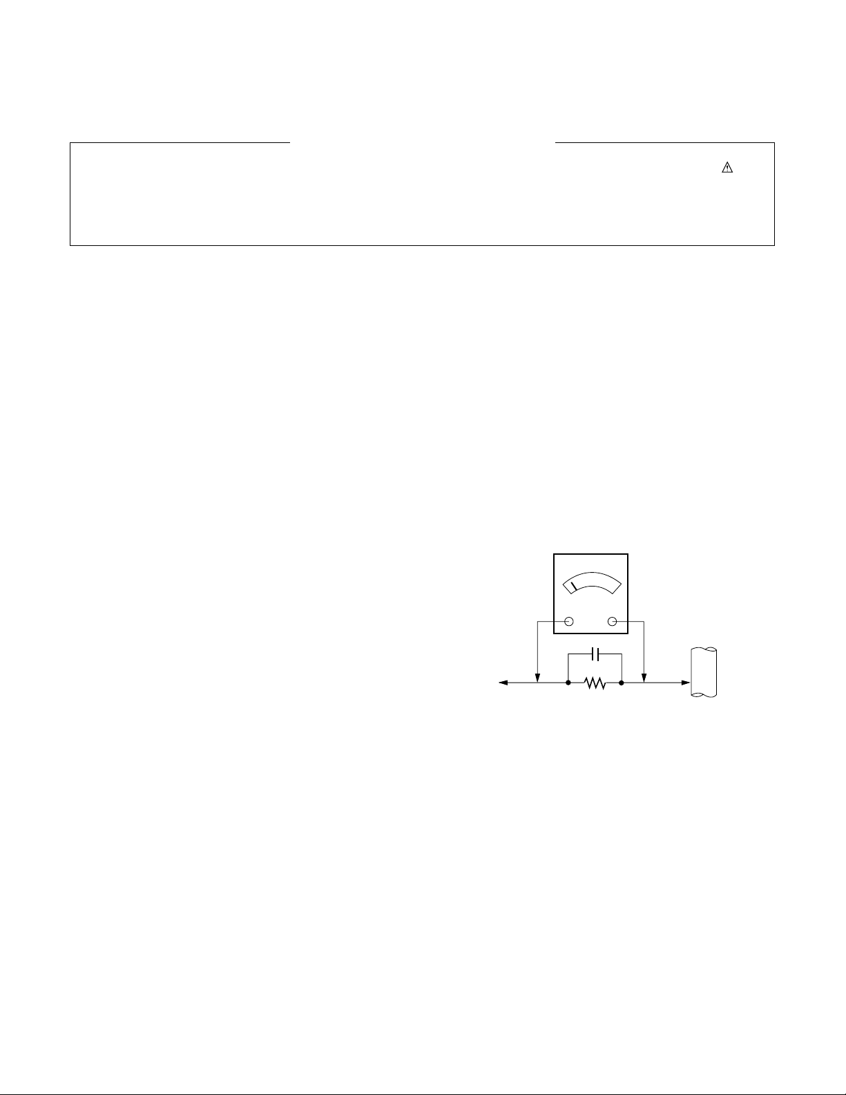
Leakage Current Hot Check (See below Figure)
Plug the AC cord directly into the AC outlet.
Do not use a line Isolation Transformer during this check.
Connect 1.5 K / 10 watt resistor in parallel with a 0.15 uF capacitor
between a known good earth ground (Water Pipe, Conduit, etc.)
and the exposed metallic parts.
Measure the AC voltage across the resistor using AC voltmeter
with 1000 ohms/volt or more sensitivity.
Reverse plug the AC cord into the AC outlet and repeat AC voltage
measurements for each exposed metallic part. Any voltage
measured must not exceed 0.75 volt RMS which is corresponds to
0.5 mA.
In case any measurement is out of the limits specified, there is
possibility of shock hazard and the set must be checked and
repaired before it is returned to the customer.
Leakage Current Hot Check circuit
1.5 Kohm/10W
To Instrument’s
exposed
METALLIC PARTS
Good Earth Ground
such as WATER PIPE,
CONDUIT etc.
AC Volt-meter
When 25A is impressed between Earth and 2nd Ground
for 1 second, Resistance must be less than 0.1
*Base on Adjustment standard
IMPORTANT SAFETY NOTICE
0.15 uF
Ω
LGE Internal Use OnlyCopyright © 2010 LG Electronics. Inc. All right reserved.
Only for training and service purposes
- 4 -
SPECIFICATION
NOTE : Specifications and others are subject to change without notice for improvement
.
4. Electrical specification
1. Application range
This spec sheet is applied to LCD TV used LP91H chassis.
2. Specification
Each part is tested as below without special appointment.
1) Temperature : 25 ºC ± 5 ºC(77 ºF ± 9 ºF), CST : (40 ±5) ºC
2) Relative Humidity : 65 % ± 10 %
3) Power Voltage
: Standard input voltage(AC 100-240 V~ 50 / 60 Hz)
* Standard Voltage of each products is marked by models.
4) Specification and performance of each parts are followed
each drawing and specification by part number in
accordance with BOM.
5) The receiver must be operated for about 5 minutes prior to
the adjustment.
3. Test method
1) Performance: LGE TV test method followed
2) Demanded other specification
- Safety: CE, IEC specification
- EMC : CE, IEC
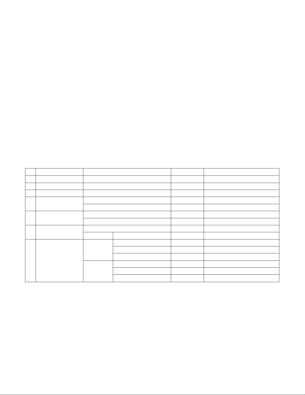
No. Item Specification Measurement Remark
1 Screen Size 55 cm(22 inch) wide Color Display Module Resolution : 1366*768
2 Aspect Ratio 16:9
3 LCD Module 55 cm(22 inch) TFT WXGA LCD
4 Operating Environment Temp. : 0 deg ~ 40 deg
Humidity : 0 % ~ 85 %
5 Storage Environment Temp. : -20 ~ 60 deg
Humidity : 0 % ~ 85 %
6 Input Voltage AC 100-240 V~ 50 / 60 Hz
26.05 W HD
7 LCD Module LGD 501 x 297 x 17.3 Outline Dimension
116.5 x 349.5 Pixel Pitch
4 CCFLs Backlight assembly
CMO 481.5 x 272.5 Outline Dimension
0.1165 x 0.3495 Pixel Pitch
4 CCFL Backlight assembly
- 5 -
LGE Internal Use OnlyCopyright © 2010 LG Electronics. Inc. All right reserved.
Only for training and service purposes
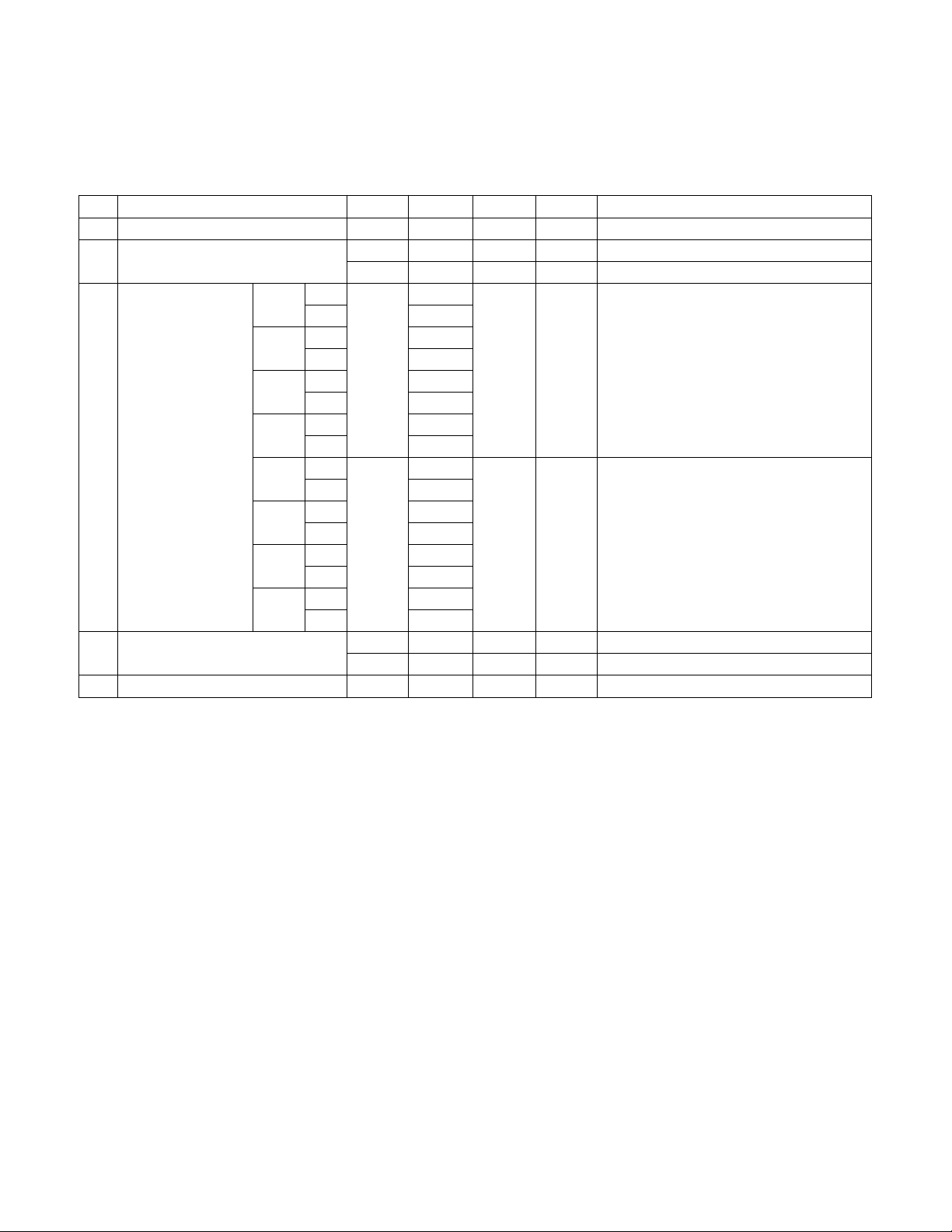
No. Item Min. Typ. Max. Unit Remark
1. Luminance (W/O PC mode) 185 250 cd/m
2
2. VIew angle (R/L, U/D) 170 / 158 degree LGD
170 / 160 CMO
3. Color Coordinates White X Typ 0.285 Typ LGD (HD)
Y -0.03 0.293 +0.03
RED X 0.642
Y 0.333
Green X 0.295
Y 0.608
Blue X 0.147
Y 0.063
White X Typ 0.285 Typ CMO (HD)
Y -0.03 0.293 +0.03
RED X 0.644
Y 0.331
Green X 0.273
Y 0.588
Blue X 0.151
Y 0.061
4. Module Contrast ratio 700 1,000 LGD
750 1,000 CMO
5. Luminance Variation 1.3
5. Chroma& Brightness (Optical)
(1) LCD Module
The Color Coordinates check condition
- 50 cm from the surface, Full White Pattern
- Picture mode Vivid
- 6 -
LGE Internal Use OnlyCopyright © 2010 LG Electronics. Inc. All right reserved.
Only for training and service purposes
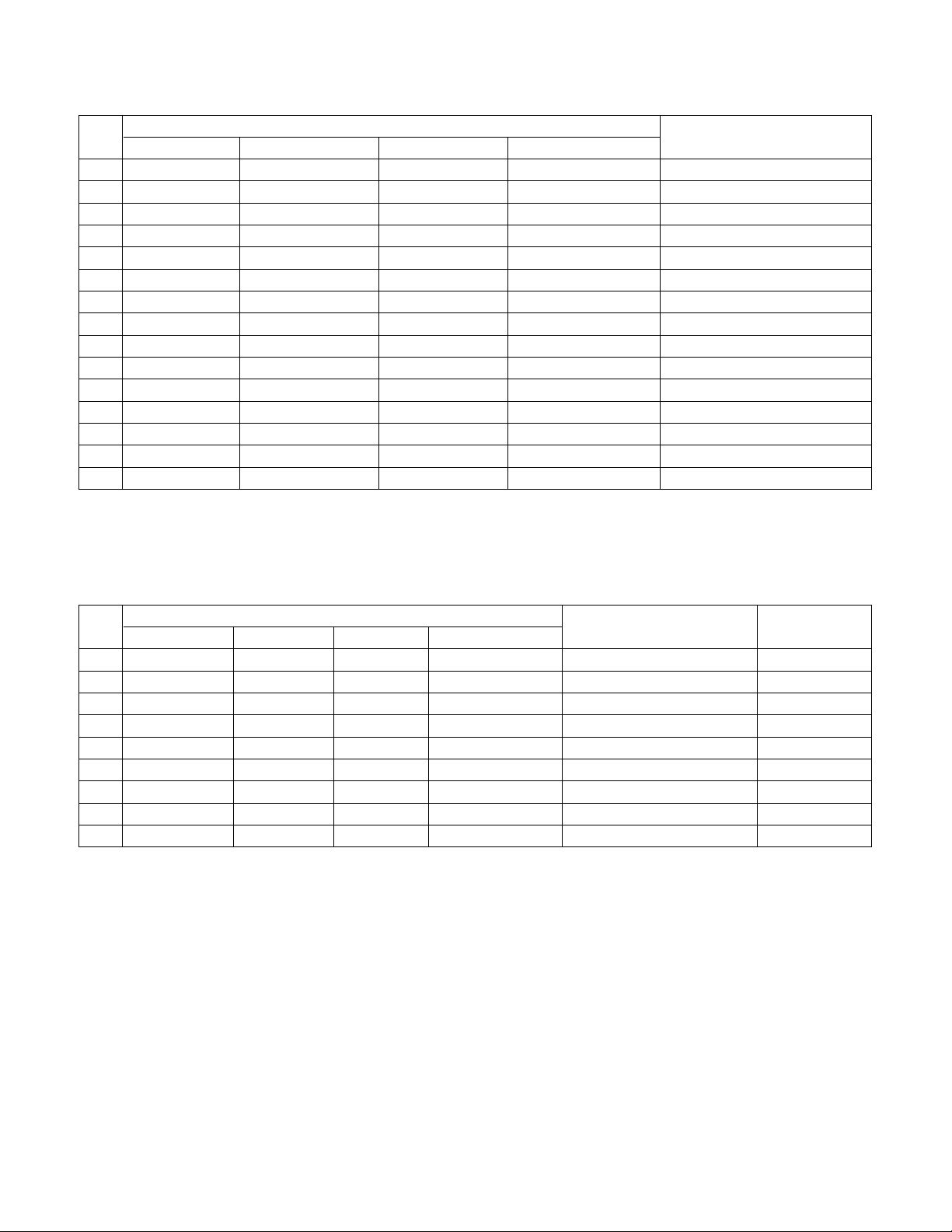
No.
Specification
Proposed Remarks
Resolution H-freq(kHz) V-freq(Hz) Pixel Clock(MHz)
1 640* 350 31.468 70.09 25.17 EGA
2 720* 400 31.469 70.09 28.32 DOS
3 640* 480 31.469 59.94 25.17 VESA( VGA)
4 800* 600 37.879 60.317 40 VESA( SVGA)
5 1024* 768 48.363 60.004 65 VESA( XGA)
6 1280* 768 47.776 59.87 79.5 VESA( WXGA)
7 1360* 768 47.72 59.799 84.75 VESA( WXGA)
8 1280* 1024 63.668 59.895 109.00 XGA Only FHD Model
9 1920* 1080 66.587 59.934 138.50 WUXGA(Reduced Blanking) Only FHD Model
7. RGB
(Analog PC, RGB-DTV - NOT SUPPORT)
6. Component Video Input (Y, PB, PR)
No.
Specification
Remarks
Resolution H-freq(kHz) V-freq(Hz) Pixel Clock(MHz)
1 720* 480 15.73 59.94 13.500 SDTV, DVD 480I( 525I)
2 720* 480 15.75 60.00 13.514 SDTV, DVD 480I( 525I)
3 720* 576 15.625 50.00 13.500 SDTV, DVD 576I( 625I) 50 Hz
4 720* 480 31.47 59.94 27.000 SDTV 480P
5 720* 480 31.50 60.00 27.027 SDTV 480P
6 720* 576 31.25 50.00 27.000 SDTV 576P 50 Hz
7 1280* 720 44.96 59.94 74.176 HDTV 720P
8 1280* 720 45.00 60.00 74.250 HDTV 720P
9 1280* 720 37.50 50.00 74.25 HDTV 720P 50 Hz
10 1920* 1080 28.125 50.00 74.250 HDTV 1080I 50 Hz,
11 1920* 1080 33.72 59.94 74.176 HDTV 1080I
12 1920* 1080 33.75 60.00 74.25 HDTV 1080I
13 1920* 1080 56.25 50 148.5 HDTV 1080P
14 1920* 1080 67.432 59.94 148.350 HDTV 1080P
15 1920* 1080 67.5 60.00 148.5 HDTV 1080P
- 7 -
LGE Internal Use OnlyCopyright © 2010 LG Electronics. Inc. All right reserved.
Only for training and service purposes
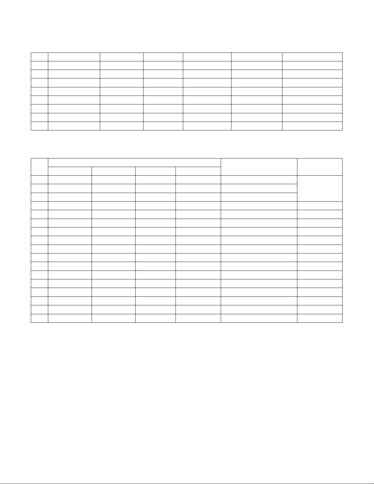
8. HDMI Input(PC)
(PC-Spec. out but it can be shown the picture at only HDMI/ DVI IN 1 via DVI to HDMI Cable)
No. Resolution H-freq(kHz) V-freq.(Hz) Pixel clock(MHz) Proposed Remarks
1 640 x 480 31.469 59.94 25.17 VESA(VGA)
2 800 x 600 37.879 60.317 40.00 VESA(SVGA)
3 1024 x 768 48.363 60.004 65.00 VESA(XGA)
4 1280 x 768 47.776 59.87 79.5 VESA(WXGA)
5 1360 x 768 47.72 59.799 84.62 VESA(WXGA)
6 1366 x 768 47.7 60.00 84.62 WXGA
7 1280 x 1024 63.595 60.00 108.875 SXGA
8 1920 x 1080 66.647 59.988 138.625 WUXGA
9. HDMI Input(DTV)
No.
Specification
Proposed Remarks
Resolution H-freq(kHz) V-freq(Hz) Pixel Clock(MHz)
1 720 x 480 15.73 59.94 13.500 SDTV, DVD 480I(525I) Spec. out
2 720 x 480 15.75 60.00 13.514 SDTV, DVD 480I(525I) but display.
3 720 x 576 15.625 50.00 13.500 SDTV, DVD 576I(625I) 50 Hz
4 720 x 480 31.47 59.94 27 SDTV 480P
5 720 x 480 31.5 60.00 27.027 SDTV 480P
6 720 x 576 31.25 50.00 27 SDTV 576P
7 1280 x 720 44.96 59.94 74.176 HDTV 720P
8 1280 x 720 45 60.00 74.25 HDTV 720P
9 1280 x 720 37.5 50.00 74.25 HDTV 720P
10 1920 x 1080 28.125 50.00 74.25 HDTV 1080I
11 1920 x 1080 33.72 59.94 74.176 HDTV 1080I
12 1920 x 1080 33.75 60.00 74.25 HDTV 1080I
13 1920 x 1080 56.25 50.00 148.5 HDTV 1080P
14 1920 x 1080 67.432 59.94 148.350 HDTV 1080P
15 1920 x 1080 67.5 60.00 148.5 HDTV 1080P
16 1920 x 1080 27 24.00 74.25 HDTV 1080P
17 1920 x 1080 33.75 30.00 74.25 HDTV 1080P
LGE Internal Use OnlyCopyright © 2010 LG Electronics. Inc. All right reserved.
Only for training and service purposes
- 8 -
ADJUSTMENT INSTRUCTION
1. Application Range
This specification sheet is applied to all of the LCD TV, LP91H
chassis.
2. Specification
(1) Because this is not a hot chassis, it is not necessary to use
an isolation transformer. However, the use of isolation
transformer will help protect test instrument.
(2) Adjustment must be done in the correct order.
(3) The adjustment must be performed in the circumstance of
25 °C ± 5 °C of temperature and 65 % ± 10 % of relative
humidity if there is no specific designation.
(4) The input voltage of the receiver must keep AC 100-220
V~ 50 / 60 Hz.
(5) Before adjustment, execute Heat-Run for 5 minutes at RF
no signal.
3. Adjustment items
3.1. PCB assembly adjustment items
(1) Download the MSTAR main software
(IC800, Mstar ISP Utility)
1) Using D/L Jig
2) Using USB Memory Stick.
(2) Input Tool-Option.
(3) Download the EDID
- EDID datas are automatically downloaded when adjusting
the Tool Option2
(4) ADC Calibration - RGB / Component
(4) Check SW Version.
3.2. SET assembly adjustment items
(1) Input Area option
(2) Adjustment of White Balance : Auto & Manual
(3) Input Tool-Option/Area option
(4) Intelligent Sensor Inspection Guide
(5) Preset CH information
(6) Factoring Option Data input
4. PCB assembly adjustment method
4.1. Mstar Main S/W program download
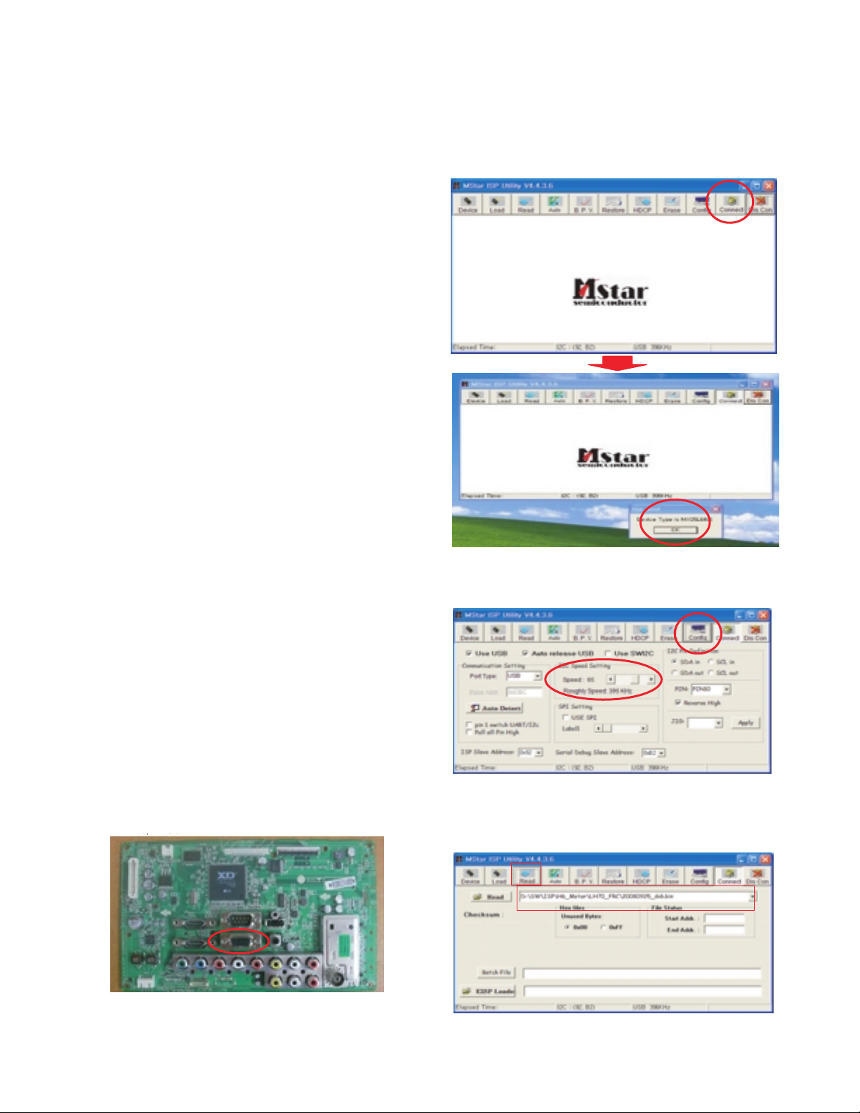
4.1.1. Using D/L Jig
(1) Preliminary steps
1) Connect the download jig to D-sub(RGB) jack.
(2) Download steps
1) Execute ‘ISP Tool’ program, the main window(Mstar ISP
utility Vx.x.x) will be opened.
2) Click the “Connect” button and confirm “Dialog Box”
3) Click the “Config.” button and Change speed I2C Speed
setting : 350 Khz ~ 400 Khz
4) Read and write bin file.
Click “(1)Read” tab, and then load download file
(XXXX.bin) by clicking “Read”.
- LH20/ LH30
1
Filexxx.bin
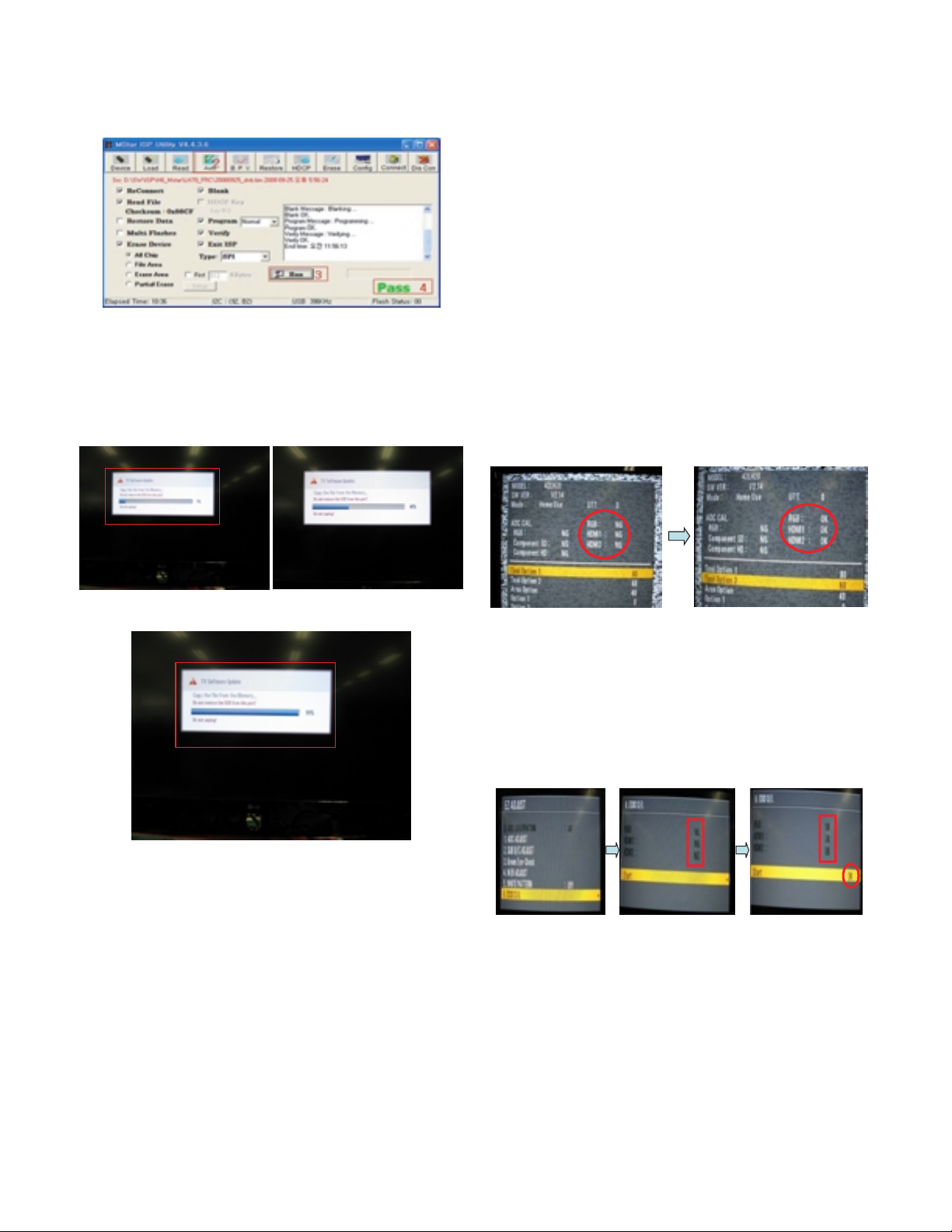
5) Click “(2) Auto” tab and set as below.
6) Click “(3) Run”.
7) After downloading, you can see the “(4) Pass” message.
4.1.2. Using the Memory Stick
* USB download : Service Mode
1) Insert the USB memory stick to the ISB port.
2) Automatically detect the SW Version.
-> S/W download process is executed automatically.
3) Show the message “Copy the file from the Memory”.
4) After Finished the Download, Automatically DC Off -> On
5) Check The update SW Version.
4.2. Input tool option.
Adjust tool option refer to the BOM.
- Tool Option Input : PCBA Check Process
- Area Option Input : Set Assembly Process
After Input Tool Option and AC off
Before PCBA check, you have to change the Tool option and
have to AC off/on (Plug out and in)
(If missing this process, set can operate abnormally)
(1) Profile : Must be changed the option value because being
different with some setting value depend on
module maker, inch and market
(2) Equipment : adjustment remote control.
(3). Adjustment method
- The input methods are same as other chassis.(Use IN-
START Key on the Adjust Remocon.)
(If not changed the option, the input menu can differ the
model spec.)
Refer to Job Expression of each main chassis assembly
(EBTxxxxxxxx) for Option value
Caution : Don’t Press “IN-STOP” key after completing the
function inspection.
4.3. EDID D/L method
Recommend that don’t connect HDMI and RGB(D-SUB) cable
when downloading the EDID.
If not possible, recommend that connect the MSPG equipment.
There are two methods of downloading the edid data
4.3.1. 1st Method
EDID datas are automatically downloaded when adjusting the
Tool Option2.
Automatically downloaded when pushing the enter key after
adjusting the tool option2.
It takes about 2seconds.
4.3.2. 2nd Method
* Caution :
Must be checked that the tool option is right or not.
If tool option is wrong, hdmi edid data could not be
downloaded well.
1) Press the ADJ key
2) Move to the EDID D/L and Press the right direction key(
G).
3) Press the right direction key(
G) at Start.
4) After about a few seconds, appear “OK”, then compete.
4.3.3. RS-232C command Method
(1) Command : AE 00 10
* Caution
Don’t connect HDMI and RGB(D-SUB) cable when
downloading the EDID.
If the cables are connected, Downloading of edid could be
failed.
- 9 -
LGE Internal Use OnlyCopyright © 2010 LG Electronics. Inc. All right reserved.
Only for training and service purposes
1
Filexxx.bin
 Loading...