

LG 21SA1RL Schematic
COLOR TV
SERVICE MANUAL
CAUTION
BEFORE SERVICING THE CHASSIS,
READ THE SAFETY PRECAUTIONS IN THIS MANUAL.
CHASSIS : CW81B
MODEL : 21SA1RL/RG/RLX
MODEL :
21SA1RL/RG/RLX-L4
North/ Latin America http://aic.lgservice.com
Europe/Africa http://eic.lgservice.com
Asia/Oceania http://biz.lgservice.com
Aug., 2009
Printed in ChinaP/NO : MFL42466416
Internal Use Only

- 2 -
Copyright©2009 LG Electronics.Inc. All right reserved.
Only for training and service purposes.
LGE Internal Use Only
CONTENTS
SAFETY PRECAUTIONS ...........................................................................................................................................................................3
ADJUSTMENT INSTRUCTIONS ................................................................................................................................................................4
TROUBLE SHOOTING..............................................................................................................................................................................12
EXPLODED VIEW.....................................................................................................................................................................................16
SCHEMATIC DIAGRAM ...............................................................................................................................................................................
PRINTED CIRCUIT BOARD..........................................................................................................................................................................
BLOCK DIAGRAM.........................................................................................................................................................................................
SPECIFICATIONS
POWER INPUT ....................................................................................................................................................... AC100-240V~50/60Hz
POWER CONSUMPTION ....................................................................................................................................................................85W
ANTENNA INPUT IMPEDANCE .....................................................................................................................VHF/UHF 75 ohm Balanced
CHANNEL RANGE
VHF .................................................................................................................................................................................................. 2-13
UHF ................................................................................................................................................................................................. 14-69
CATV(125) .................................................................................................................................................................01, 02
¡› 13, 14¡› 125
INTERMEDIATE FREQUENCIES
Picture I-F carrier frequency........................................................................................................................................................45.75MHz
Sound I-F carrier frequency ......................................................................................................................................................41.25 MHz
Color Sub-carrier frequency ..................................................................................................................................................... 42.17 MHz
Center frequency ............................................................................................................................................................................44 MHz
CHASSIS CONSTRUCTION ..................................................................................................................................... IC-Solid state chassis
PICTURE TUBE ....................................................................................................................................... Type No. : A51QGV991X001(D)
SOUND OUTPUT .................................................................................................................................................................... 7W or 10W
CABINET ........................................................................................................................................................................................... Plastic
ABBREVIATIONS: Used in this book
ADJ ...............................................................Adjustment or Adjust
AFC .................................................Automatic Frequency Control
AGC.......................................................... Automatic Gain Control
AMP .................................................................................Amplifier
CRT .................................................................Cathode Ray Tube
DEF ............................................................................... Deflection
DET.................................................................................. Detector
FBT............................................................... Flyback Transformer
H.V............................................................................ High Voltage
OSC................................................................................ Oscillator
SEP................................................................................ Separator
SYNC................................................................... Synchronization
S.I.F.............................................. Sound Intermediate Frequency
V.I.F ...............................................Video Intermediate Frequency
H ....................................................................................Horizontal
V ........................................................................................Vertical
IC ......................................................................Intergrated Circuit
OSD .................................................................On-Screen Display
SAP ......................................................... Second Audio Program
BPF .....................................................................Band Pass Filter
ST ...................................................................................... Stereo
LPF .......................................................................Low Pass Filter
DP .................................................................... Differential Phase
DG .....................................................................Differential Group
PLL ................................................................ Phase Locked Loop
APC ......................................................Automatic Picture Control
BM ....................................................................................B+ Main
BT .................................................................................B+ Tuning
- 3 -
Copyright©2009 LG Electronics.Inc. All right reserved.
Only for training and service purposes.
LGE Internal Use Only
SAFETY PRECAUTIONS
1. Before returning an instrument to the customer, always make a safety
check of the entire instrument, including, but not limited to, the
following items:
a. Be sure that no built-in protective devices are defective and/or have
been defeated during servicing. (1) Protective shields are provided on
this chassis to protect both the technician and the customer. Correctly
replace all missing protective shields, including any removed for
servicing convenience. (2) When reinstalling the chassis and/or other
assemblies in the cabinet, be sure to put back in place all protective
devices, including, but not limited to, nonmetallic control knobs,
insulating fishpapers, adjustment and compartment covers/shields, and
isolation resistor/capacitor networks.
Do not operate this instrument
or permit it to be operated without all protective devices correctly
installed and functioning.
b. Be sure that there are no cabinet openings through which an adult or
child might be able to insert their fingers and contact a hazardous
voltage. Such openings include, but are not limited to, (1) spacing
between the picture tube and the cabinet back, (2) excessively wide
cabinet ventilation slots, and (3) an improperly fitted and/or incorrectly
secured cabinet back cover.
c. Antenna Cold Check-With the instrument AC plug removed from any
AC source, connect an electrical jumper across the two AC plug prongs.
Place the instrument AC switch in the on position. Connect one lead of
an ohmmeter to the AC plug prongs tied together and touch the other
ohmmeter lead in turn to each tuner antenna input exposed terminal
screw and, if applicable, to the coaxial connector. If the measured
resistance is less than 1.0 megohm or greater than 5.2 megohm, an
abnormality exists that must be corrected before the instrument is
returned to the customer. Repeat this test with the instrument AC
switch in the off position.
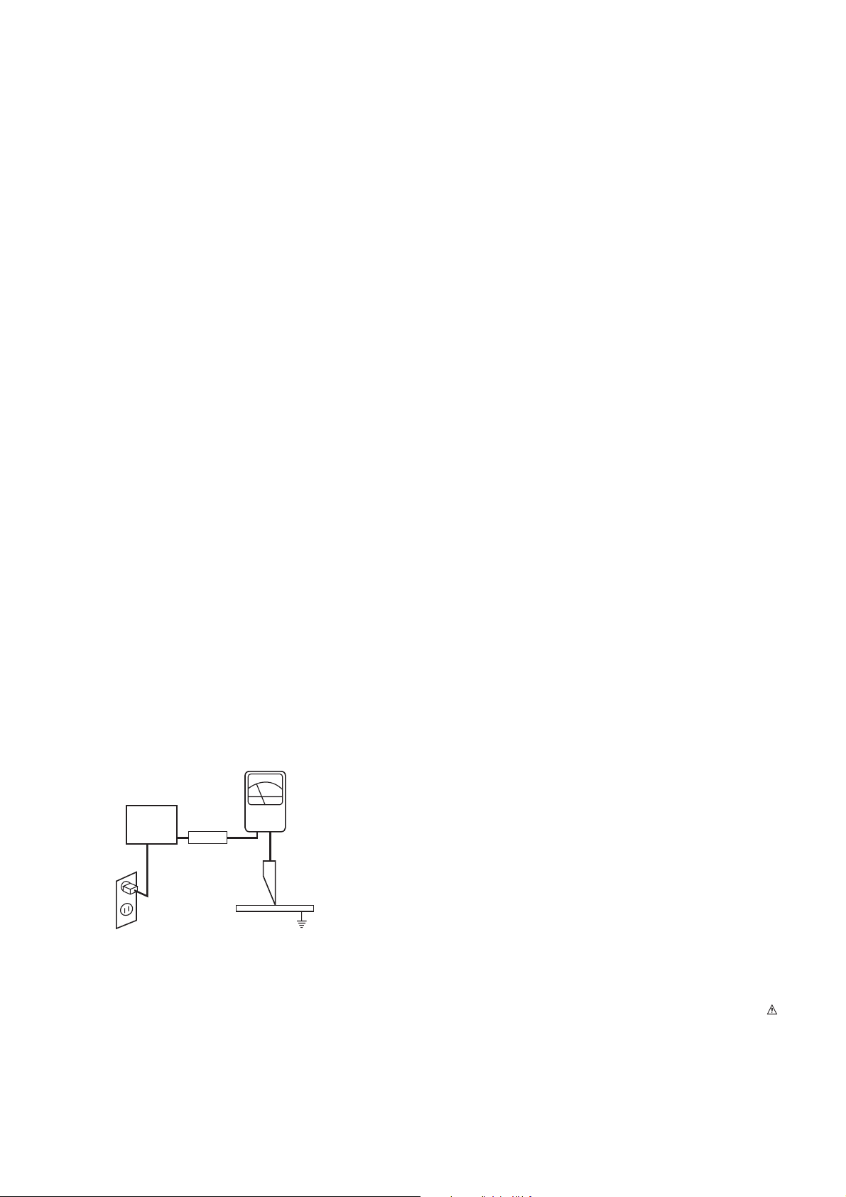
d. Leakage Current Hot Check-With the instrument completely
reassembled, plug the AC line cord directly into a 120 V AC outlet.
(Do not use an isolation transformer during this test.) Use a leakage
current tester or a metering system that complies with American
National Standards Institute (ANSI)
C101.1 Leakage Current for
Appliances and Underwriters Laboratories (UL) 1410, (50.7). With the
instrument AC switch first in the on position and then in the off position,
measure from a known earth ground (metal waterpipe, conduit, etc.) to
all exposed metal parts of the instrument (antennas, handle bracket,
metal cabinet, screwheads, metallic overlays, control shafts, etc.),
especially any exposed metal parts that offer an electrical return path to
the chassis. Any current measured must not exceed 0.5 milliamp.
Reverse the instrument power cord plug in the outlet and repeat the
test.
ANY MEASUREMENTS NOT WITHIN THE LIMITS SPECIFIED HEREIN
INDICATE A POTENTIAL SHOCK HAZARD THAT MUST BE
ELIMINATED BEFORE RETURNING THE INSTRUMENT TO THE
CUSTOMER.
e. X-Radiation and High Voltage Limits-Because the picture tube is the
primary potential source of X-radiation in solid-state TV receivers, it is
specially constructed to prohibit X-radiation emissions. For continued Xradiation protection, the replacement picture tube must be the same
type as the original. Also, because the picture tube shields and mounting
hardware perform an X-radiation protection function, they must be
correctly in place.
High voltage must be measured each time servicing is done that
involves B+, horizontal deflection, or high voltage. Correct operation of
the X-radiation protection circuits also must be reconfirmed each time
they are serviced. (X-radiation protection circuits also may be called
"horizontal disable" or "hold-down.") Read and apply the high voltage
limits and, if the chassis is so equipped, the X-radiation protection circuit
specifications given on instrument labels and in the Product Safety & Xradia
tion Warning note on the service data chassis schematic.
High voltage is maintained within specified limits by close-tolerance
safety-related components/adjustments in the high-voltage circuit.
If high voltage exceeds specified limits, check each component
specified on the chassis schematic and take corrective action.
2. Read and comply with all caution and safety-related notes on or inside
the receiver cabinet, on the receiver chassis, or on the picture tube.
3. Design Alteration Warning- Do not alter or add to the mechanical or
electrical design of this TV receiver. Design alterations and additions,
including, but not limited to, circuit modifications and the addition of
items such as auxiliary audio and/or video output connections, might
alter the safety characteristics of this receiver and create a hazard to
the user. Any design alterations or additions will void the manufacturer's
warranty and will make you, the servicer responsible for personal injury
or property damage resulting therefrom.
4. Picture Tube Implosion Protection Warning-The picture tube in this
receiver employs integral implosion protection. For continued implosion
protection, replace the picture tube only with one of the same type and
number. Do not remove, install, or otherwise handle the picture tube in
any manner without first putting on shatterproof goggles equipped with
side shields. People not so equipped must be kept safely away while
picture tubes are handled. Keep the picture tube away from your body.
Do not handle the picture tube by its neck. Some "in-line" picture tubes
are equipped with a permanently attached deflection yoke; because of
potential hazard, do not try to remove such "permanently attached"
yokes from the picture tube.
5. Hot Chassis Warning-a. Some TV receiver chassis are electrically
connected directly to one conductor of the AC power cord and may be
safely serviced without an isolation transformer only if the AC power
plug is inserted so that the chassis is connected to the ground side of
the AC power source. To confirm that the AC power plug is inserted
correctly, with an AC voltmeter measure between the chassis and a
known earth ground. If a voltage reading in excess of 1.0 V is obtained,
remove and reinsert the AC power plug in the opposite polarity and
again measure the voltage potential between the chassis and a known
earth ground. b. Some TV receiver chassis normally have 85 V AC (RMS)
between chassis and earth ground regardless of the AC plug polarity.
These chassis can be safely serviced only with an isolation transformer
inserted in the power line between the receiver and the AC power
source, for both personnel and test equipment protection. c. Some TV
receiver chassis have a secondary ground system in addition to the main
chassis ground. This secondary ground system is isolated from the AC
power line. The two ground systems are electrically separated by
insulating material that must not be defeated or altered.
6. Observe original lead dress. Take extra care to assure correct lead
dress in the following areas: a. near sharp edges, b. near thermally hot
parts- be sure that leads and components do not touch, c. the AC
supply, d. high voltage, and e.antenna wiring. Always inspect in all areas
for pinched, out-of-place, or frayed wiring. Do not change spacing
between components, and between components and the printed circuit
board. Check the AC power cord for damage.
7. Components, parts, and/or wiring that appear to have overheated or are
otherwise damaged should be replaced with components, parts, or
wiring that meet original specifications. Additionally, determine the
cause of overheating and/or damage and, if necessary, take corrective
action to remove any potential safety hazard.
8. PRODUCT SAFETY NOTICE
Some electrical and mechanical parts have special safety related
characteristics which are often not evident from visual inspection, nor can
the protection they give necessarily be obtained by replacing them with
components rated for higher voltage, wattage, etc. Parts that have
special safety characteristics are identified by shading, by a ¡,or by
on schematics and parts lists. Use of a substitute replacement that does
not have the same safety characteristics as the recommended
replacement parts might create shock, fire, and/or other hazards. Product
safety is under review continuously and new instructions are issued
whenever appropriate.
DEVICE
UNDER
TEST
TEST ALL
EXPOSED METAL
SURFACES
2-WIRE CORD
ALSO TEST WITH
PLUG REVERSED
(USING AC ADAPTER
PLUG AS REQUIRED)
EARTH
GROUND
LEAKAGE
CURRENT
TESTER
(READING SHOULD
NOT BE ABOVE
0.5mA)
+-
AC Leakage Test
1. Scope of Application
These instructions are applied to CW81B Chassis.
2. Notes
1) Because this is a cold chassis, it is not necessary to use an
isolation transformer. However, operating it using a
transformer between the power supply line and chassis input
to prevent electric shock and to protect the test instrument.
2) All adjustment must be done in the correct sequence.
However, for better productivity, it can be change in a prepermitted range.
3) Environment conditions : If not specified, it must be done in
following conditions.
Temperature : 25 ± 5°C
Humidity: 60% ± 10%
4) Power supply of SET for NTSC
Korea market: 220V±10%, 60Hz
Taiwan market: 110V±10%, 60Hz
Japan market: 100V±10%, 50/60Hz
5) If not specified, the receiver must be operated for more than
20 minutes prior to the adjustment.
6) Signal : Received the standard color signal (65dB±1dBuV).
NTSC: LG standard signal means the digital pattern 13CH
(480NC)
7) If not specified, APC ON is APC CLEAR (DYNAMIC)
3. AGC Voltage Adjustment
3-1. Necessary Instrument
- Digital Multi-meter: 1 set
- Max Input Current : Over 1A/ Max Input Voltage : 500Vdc
- Measurement Range : 10mV-100mVdc/ Accuracy : 0.03%
3-2. Adjustment Preparation
1) Input in the 75Ω cable 65dB(±1dB) LG standard signal.
2) Connect the multi-meter to J105 (AGC Check, Marking).
3-3. Adjustment
1) Press the “INSTART” key of factory remote control and
select “VP0 (RF AGC)” adjustment mode.
2) Press the VOL+/- (
F/ G) key until the multi-meter shows
reading as shown below.
3) CAUTION: Since the signal strength can be easily
changed by the condition of signal cable, you need to
check the signal strength frequently in order to prevent
error.
4. Screen Voltage Adjustment
4-1. Adjustment (Using Factory Remote Control)
1) Input in the 75Ω cable LG standard signal (Digital Pattern,
480NC).
2) Press the “ADJ’ key of factory remote control once to make
the TV set display horizontal line.
3) Turn the screen volume on the FBT clockwise until the
horizontal line is visible and turn it counterclockwise until
horizontal line faintly visible.
(Exit screen voltage adjustment by press “Enter(
A)” key of
factory remote control.)
5. Purity and Convergence Adjustment
5-1. Purity adjustment
(1) Adjustment Preparation
1) Receive Red Raster Pattern for purity adjustment (51CH).
2) Demagnetize the CPT and Cabinet with a degaussing coil.
(2) Adjustment
1) Pre-adjust the static convergence (STC) with the 4 and
6pole magnet.
2) If the horizontal Line is inline with CPT Mark, 2-Pole
magnet should direct 3-9 o’clock direction.
3) If not, direct 2-pole magnet handle toward 6-12 o’clock
direction and adjust the Horizontal Line to fall onto the
mark opening the magnet at an angle.
4) Push the DY(deflection yoke) all the way to the CPT
funnel.
5) Turn the purity magnet(2-pole magnet) so that the “green”
color portion of left side and the “blue” color portion on the
right side have equal amount of color.
6) Pull the DY slowly backward and fix it when the whole
screen becomes red.
(The specified torque for fixing DY screw should be
10Kg/cm.)
5-2. Convergency Adjustment
(1) Necessary Instrument
1) Degaussing Coil
2) Convergency fixing instrument (Speical tools)
(2) Adjustment Preparation
1) Operate the unit at least 15 minutes before adjustment.
2) Using degaussing coil, remove the stains on CPT &
Cabinet.
3) Received the Cross Hatch Pattern of Convergence. (09ch)
4) Let the Contrast in normal luminance level
.
(3) Static Convergence (STC) Adjustment
1) Receive the Cross Hatch Pattern Convergence (09ch).
G R B
- 4 -
ADJUSTMENT INSTRUCTIONS
G R B
R
G R B
Copyright©2009 LG Electronics.Inc. All right reserved.
Only for training and service purposes.
LGE Internal Use Only
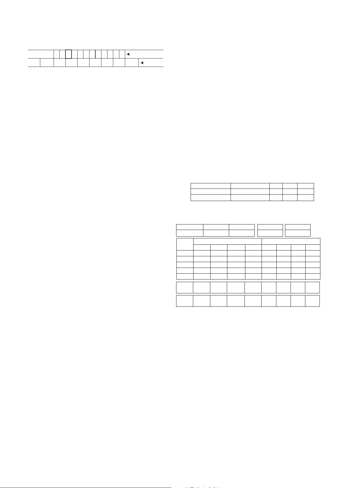
6700NFNS11E
6700VS0002F
6700PF0006B
6870NB0026A
6700MF0014A
6700MF0018A
6700MF0018B
6700MF0018D
6700MF0018E
LGIT
LGIT
SANYO
LGIT
LGIT
LGIT
LGIT
LGIT
LGIT
2.15 ± 0.05V
3.0 ± 0.05V
2.3 ± 0.05V
2.15 ± 0.05V
2.3 ± 0.05V
2.5 ± 0.05V
2.4 ± 0.05V
2.4 ± 0.05V
2.5 ± 0.05V
65dBu
65dBu
65dBu
65dBu
65dBu
65dBu
65dBu
65dBu
65dBu
TAEA-H111F
TAEW-G002D
115-B-A86EL
TAEA-J001F
TAEW-G013D
TAEA-G011D
TAEA-G001D
TAEA-G011D
TAEA-G111D
Korea
PAL
PAL
HITACHI
PAL
SECAM(CIS)
PAL
PAL
SECAM(CIS)
Tuner P/N Maker AGC Vol Signal Tuner Spec. Remark
- 5 -
2) Before adjusting Static Convergence (STC), adjust the
focus first seeing to it that the WHITE color picture quality
is sharp enough.
3) Converge the RED vertical and BLUE vertical line in unity
(same line) by changing the angle between the 2 tabs of
4-pole magnet.
4) Converge the RED horizontal and BLUE horizontal line in
unity(same line) by turning the 2 tabs of the 4-pole
magnet. At this time, do not change the angle between
the 2 tabs.
5) Converge the R, G, B vertical line in unity (same line) by
changing the angle between the 2 tabs of the 6-pole
magnet.
6) Converge the R, G, B horizontal line in unity(same line) by
turning the 2 tabs of the 6-pole magnet. At this time, do
not change the angle between the 2 tabs.
(4) Dynamic Convergence (DYC) Adjustment
1) Y-axis Adjustment:
Adjust convergence of Y-axis (vertical) by moving the
deflection yoke (DY) left and right.
2) X-axis Adjustment:
Adjust convergence of X-axis (horizontal) by moving the
deflection yoke (DY) up and down.
6. White Balance Adjustment
6-1. Necessary Instrument
1) Automatic White Balance Meter (Low/High light Pattern
generator)
2) CRTColor Analyzer, CA -100: 1 set
3) Factory Remote Control
6-2. Adjustment Preparation
Prior to this adjustment, the Screen Voltage adjustment
should be finished.
6-3. Automatic adjustment
1) Adjust using Auto White Balance Meter.
2) Enter CPU OFF Mode by pressing “IN-START” & “MUTE”
key of factor remote control in turn before adjustment.
Exit CPU OFF mode by press the “MUTE” key of factory
remote control after adjustment finished.
* In case there is excess RED color at screen voltage
adjustment, adjust it using “volume - (
F) key of factory remote
control until the RED color disappear.
6-4. Manual adjustment
1) Adjust using white Balance meter and factory remote
control.
2) Enter white balance adjustment mode by pressing
“INSTART” key of factory remote control.
3) Use the CH
D, CHE Key to choose adjustment item.
4) Use the VOL
F, VOLG Key to change item data.
5) Adjustment Procedure
a. Make the picture luminance 45Ft-L by changing the
“CONTRAST” and “BRIGHTNESS”.
b. Adjust X data of High light with R-DRIVE and Y data of
high light with B-DRIVE to have the color temperature
as shown below.
c. Make the picture luminance 4.5Ft-L by changing the
“CONTRAST” and “BRIGHTNESS”.
d. Adjust X data of low light with R-BIAS and Y data of low
light with B-BIAS to have the color temperature as
shown below.
e. Repeat steps a~d until both low and high light have the
same readings as shown below.
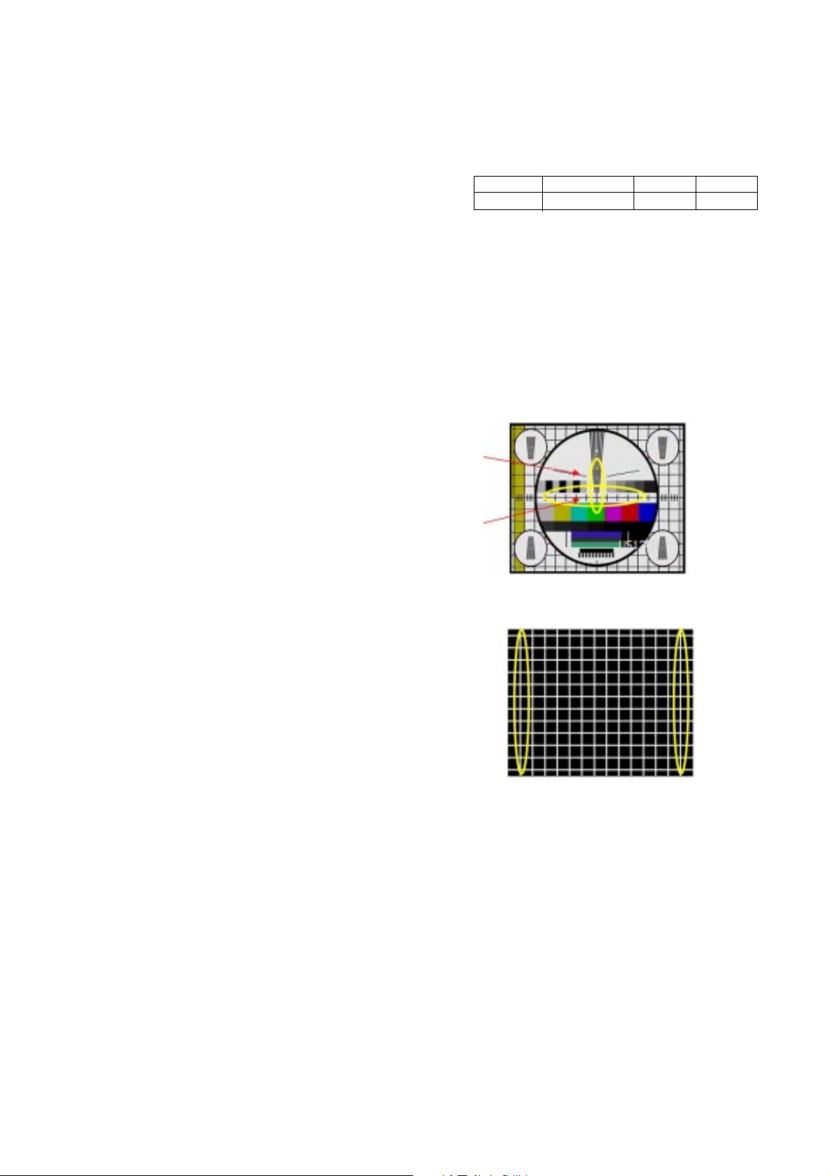
7. Focus Voltage Adjustment
This adjustment must be done after operating the TV set
receiver sufficiently.
7-1. Adjustment Preparation
Receive LG standard pattern (NTSC: Crosshatch pattern, Ch.09)
and set the picture condition on “APC ON”(CLEAR) mode.
7-2. Adjustment
Turn the focus volume on the FBT upper direction to have
the best focus vertical line (Fig. 1(a)) and horizontal line (Fig.
1(b)) as shown below
In ultra NTSC model, do in the signal of Ch.09 (Crosshatch
pattern) refer to <Fig. 2>
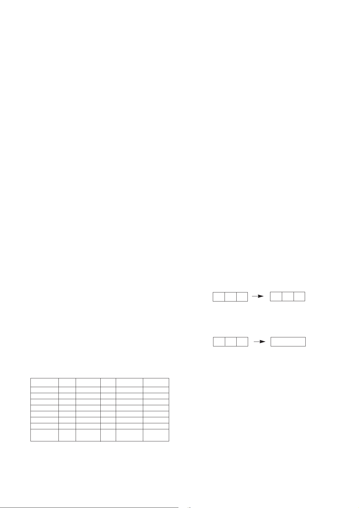
8. SUB-BRIGHTNESS Adjustment
This adjustment must be done after White balance adjustment.
8-1. Adjustment Preparation
1) Receive LG standard Mono scope pattern. (14CH)
2)Set the picture condition on " APC ON" (CLEAR) mode.
8-2. Adjustment
1) Press the “ADJ” key of the factory remote control twice to
enter to “SUB-BRIGHTNESS” adjustment mode.
2) Change the Sub-Brightness data by pressing the VOL
F,
VOL
G key so that the number 1 in gray scale of mono
scope pattern almost disappear . In the ultraslim , do until
the number "1" completely disappear.
See <Fig. 3>
Market Color Temperature X-AXIS Y-AXIS
ALL 13,000 268±5 273±5
<Fig. 1>
<Fig. 2>
Copyright©2009 LG Electronics.Inc. All right reserved.
Only for training and service purposes.
LGE Internal Use Only
(a)
(b)
- 6 -
8-3. Sub-Tint adjustment
This adjustment has to be done only if the picture has bad tint
otherwise, it can be omitted if the picture has good tint.
1) Receive LG standard pattern signal (SMPTE, 2CH)
2) Set the picture condition on “APC ON” (CLEAR) mode.
3) Press the “ADJ” key of the factory remote control three
times to enter to “SUB-TINT” adjustment mode.
4) Change the Sub-Tint data by pressing the VOL
F, VOLG
key until the upper and lower CYAN color becomes same
color.
9. Deflection setting data adjustment
These adjustment will be done by automatic adjustment
Equipment.
For manual adjustment, it is also possible by the following
procedure.
9-1. Adjustment Preparation
1) Deflection setting data adjustment can be done only with
remote control.
2) Press “IN-START” key on factory remote control continuously
to enter to Deflection Adjustment mode.
3) Press the CH
D, E key to select adjustment item.
4) Press the VOL
F, G key to change the data.
9-2. Adjustment
1) Horizontal Position Adjustment
Select SVC02(H-POS) and adjust so that the left and right
vertical line are symmetrical as possible.
2) Vertical Position Adjustment
Select SVC02(V-POS) and adjust so that the horizontal
center line coincide with geometric horizontal center of the
CPT.
3) Vertical Size Adjustment
Select SVC02(VA) and adjust so that the middle circle of the
Digital Pattern(480NC, 13CH) coincide with the effective
screen of CPT.
9-3. Adjustment (21'' Superslim, Ultra S/S
Model)
1) Vertical Position Adjustment
Select SVC02(V-POS) and adjust so that the horizontal
center line coincide with geometric horizontal center of the
CPT.
2) Vertical linearity Adjustment
Select SVC02(V-LIN) and adjust so that the size of the upper
circle is alike with the one of the lower circle at LG standard
pattern (PAL: EU05CH, NTSC: 13CH)
3) Vertical Size Adjustment
Select SVC02(VA) and adjust so that the middle circle of the
Digital Pattern(480NC, 13CH) coincide with the effective
screen of CPT.
4) Horizontal Position Adjustment
Select SVC02(H-POS) and adjust so that the left and right
vertival line are symmetrical as possible.
5) Horizontal Size Adjustment
Select SVC02(EW WIDTH) and adjust so that the outer line of
the left and right and the remotest grid will correspond to the
effective boundary surface. (The remotest grid PAL: within
0~25%; NTSC: within 2.5~3.0 column)
6) Parabora Adjustment
Select SVC02(EW PARAB) and adjust so that the vertical line
of the remotest grid at the left or right side of the screen will
be parallel to the vertical line of the center of screen. (or the
remotest grid of CPT)
7) Trapezoidal Adjustment
Select SVC02(EW TRAPE) and adjust so that the width of
the upper part of screen is alike with the one of the lower part
of the screen.
8) EW UPCOR / LOCOR Adjustment
Select SVC02(EW UPCOR, EW LOCOR) and adjust so that
the vertical line in the four corners become straight line.
9) BOW Adjustment
Select SVC02(HP BOW) and adjust so that the vertical line in
the four corners become straight line.
10. IIC BUS SUB Adjustment Data
Table
11. Auto Adjustment Preparation
Setting Table
Copyright©2009 LG Electronics.Inc. All right reserved.
Only for training and service purposes.
LGE Internal Use Only
0 1 2 3 4 5 6 7 8 9
Gray Scale
Color Bar
<Fig. 3> MONO SCOPE Patter Signal
OSD
SUB-BRIGHTNESS
SUB-TINT
Range
0 ~ 100
-20 (R) ~ +20 (G)
PAL
40
R5
Secam
40
R5
PAL
40
R5
NTSC
40
R1
Speed
1
SLave ADD
VIDEO ICBAEEPROM
A0
Delay
5
EEPROM
Sub Add
8D 8A 8F 8C
SpeedPlus
Step/Data
3 3 3 3
Sub Add
Start Bit
Stop Bit
Masking
Direction
VCD
TV PC
R DRIVE
D
6
0
0
1
R BIAS
A
7
0
0
1
B DRIVE
F
6
0
0
1
B BIAS
C
7
0
0
1
B AMP B CUT G AMP G CUT
 Loading...