

LG 21FX5REE, 21FX5RG, 21FX5RGP Service Manual

COLOR TV
SERVICE MANUAL
CAUTION
BEFORE SERVICING THE CHASSIS,
READ THE SAFETY PRECAUTIONS IN THIS MANUAL.
CHASSIS : MC-049B
MODEL : 21FX5REE/RG/RGP
MODEL :
21FX5REE/RG/RGP-TB
website:http://biz.LGservice.com
e-mail:http://www.LGEservice.com/techsup.html

- 2 -
CONTENTS
Contents...................................................................................................................2
Safety Precautions..............................................................................................3
Control Descriptions..........................................................................................4
Specifications........................................................................................................7
Adjustment Instructions .................................................................................8
Trouble Shooting.................................................................................................12
Printed circuit board.........................................................................................16
Block Diagram......................................................................................................19
Exploded View....................................................................................................20
Exploded View Parts List ..............................................................................21
Replacement Parts List .................................................................................22
SVC. Sheet..................................................................................................................
- 3 -
SAFETY PRECAUTIONS
Many electrical and mechanical parts in this chassis have special safety-related characteristics. These parts are identified by in
the Schematic Diagram and Replacement Parts List.
It is essential that these special safety parts should be replaced with the same components as recommended in this manual to
prevent X-RADIATION, Shock, Fire, or other Hazards.
Do not modify the original design without permission of manufacturer.
General Guidance
An isolation Transformer should always be used during
the servicing of a receiver whose chassis is not isolated from
the AC power line. Use a transformer of adequate power rating
as this protects the technician from accidents resulting in
personal injury from electrical shocks.
It will also protect the receiver and it's components from being
damaged by accidental shorts of the circuitry that may be
inadvertently introduced during the service operation.
If any fuse (or Fusible Resistor) in this TV receiver is blown,
replace it with the specified.
When replacing a high wattage resistor (Oxide Metal Film
Resistor, over 1W), keep the resistor 10mm away from PCB.
Keep wires away from high voltage or high temperature parts.
Due to high vacuum and large surface area of picture tube,
extreme care should be used in handling the Picture Tube.
Do not lift the Picture tube by it's Neck.
X-RAY Radiation
Warning:
To determine the presence of high voltage, use an accurate
high impedance HV meter.
Adjust brightness, color, contrast controls to minimum.
Measure the high voltage.
The meter reading should indicate
23.5
± 1.5KV: 14-19 inch, 26 ± 1.5KV: 19-21 inch,
29.0
± 1.5KV: 25-29 inch, 30.0 ± 1.5KV: 32 inch
If the meter indication is out of tolerance, immediate service
and correction is required to prevent the possibility of
premature component failure.
Before returning the receiver to the customer,
always perform an AC leakage current check on the exposed
metallic parts of the cabinet, such as antennas, terminals, etc.,
to be sure the set is safe to operate without damage of
electrical shock.
Leakage Current Cold Check(Antenna Cold Check)
With the instrument AC plug removed from AC source,
connect an electrical jumper across the two AC plug prongs.
Place the AC switch in the on position, connect one lead of
ohm-meter to the AC plug prongs tied together and touch other
ohm-meter lead in turn to each exposed metallic parts such as
antenna terminals, phone jacks, etc.
If the exposed metallic part has a return path to the chassis, the
measured resistance should be between 1MΩ and 5.2MΩ.
When the exposed metal has no return path to the chassis the
reading must be infinite.
An other abnormality exists that must be corrected before the
receiver is returned to the customer.
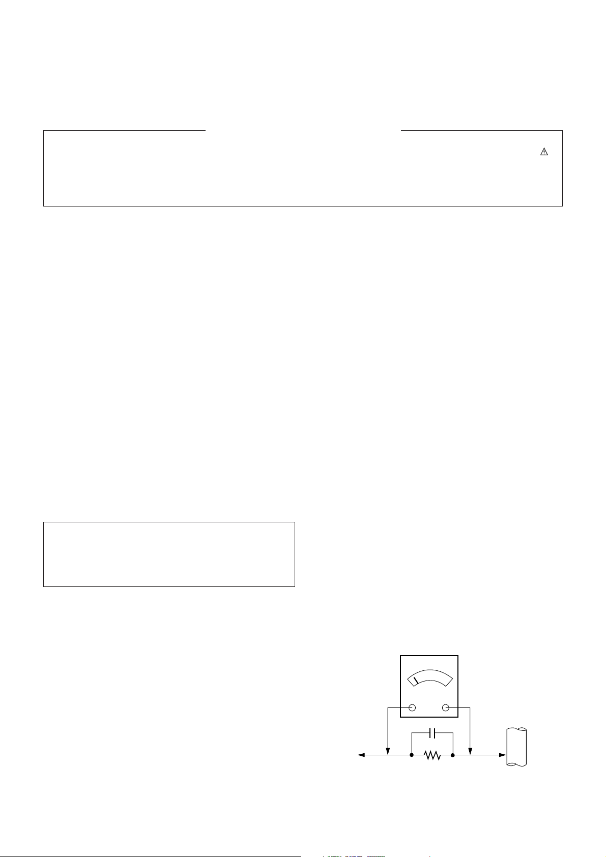
Leakage Current Hot Check (See below Figure)
Plug the AC cord directly into the AC outlet.
Do not use a line Isolation Transformer during this check.
Connect 1.5K/10watt resistor in parallel with a 0.15uF capacitor
between a known good earth ground (Water Pipe, Conduit, etc.)
and the exposed metallic parts.
Measure the AC voltage across the resistor using AC
voltmeter with 1000 ohms/volt or more sensitivity.
Reverse plug the AC cord into the AC outlet and repeat AC
voltage measurements for each exposed metallic part. Any
voltage measured must not exceed 0.75 volt RMS which is
corresponds to 0.5mA.
In case any measurement is out of the limits specified, there is
possibility of shock hazard and the set must be checked and
repaired before it is returned to the customer.
Leakage Current Hot Check circuit
The source of X-RAY RADIATION in this TV receiver is the
High Voltage Section and the Picture Tube.
For continued X-RAY RADIATION protection, the
replacement tube must be the same type tube as specified in
the Replacement Parts List.
IMPORTANT SAFETY NOTICE
0.15uF
AC Volt-meter
Good Earth Ground
such as WATER PIPE,
To Instrument's
exposed
METALLIC PARTS
CONDUIT etc.
1.5 Kohm/10W
- 4 -
DESCRIPTION OF CONTROLS
All the functions can be controlled with the remote control handset.
Some functions can also be adjusted with the buttons on the front
panel of the set.
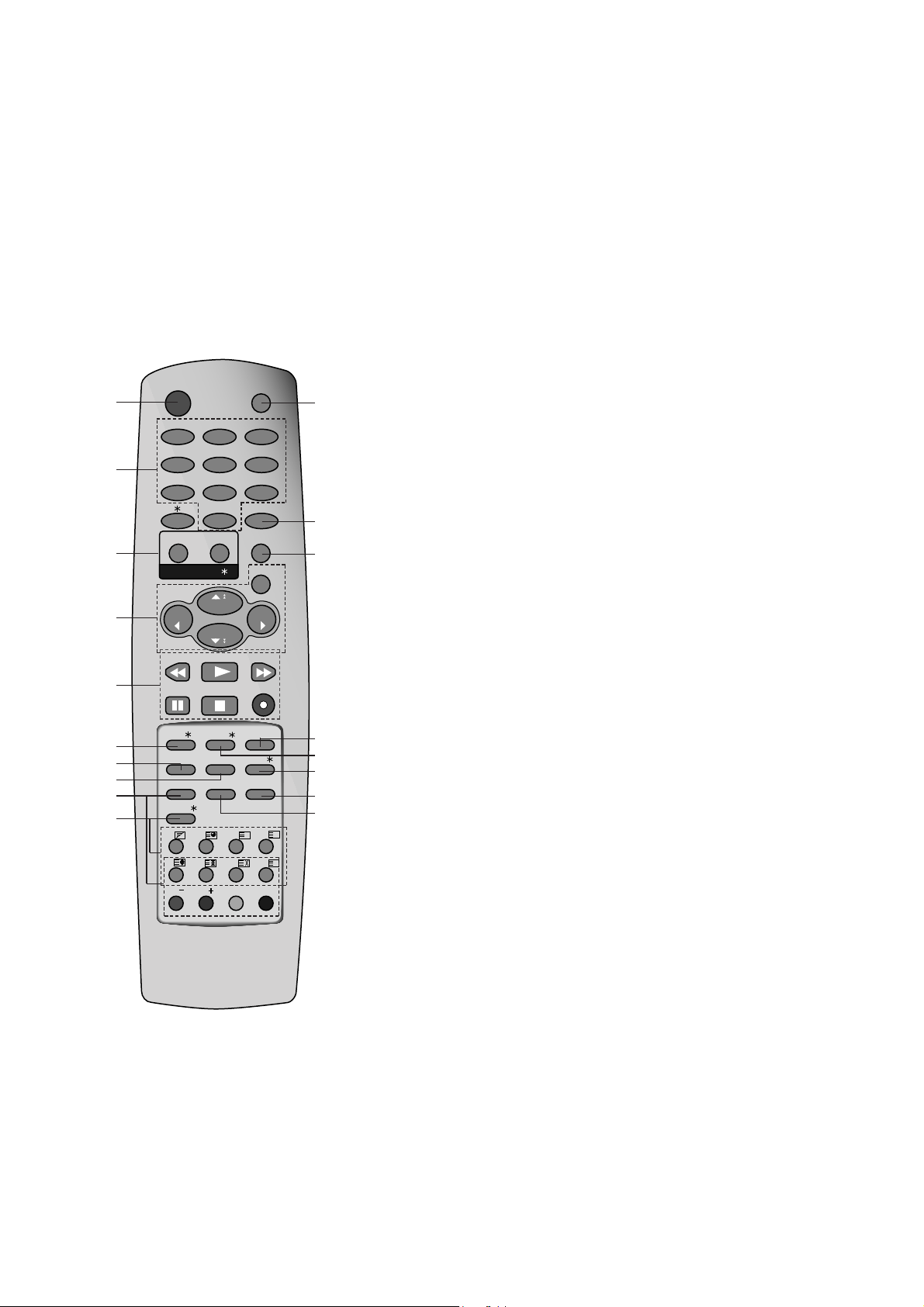
Remote control handset
Before you use the remote control handset, please install the batteries. See the next page.
1. POWER
switches the set on from standby or off to standby.
2. NUMBER BUTTONS
switches the set on from standby or directly select a number.
3. MENU (or INDEX)
selects a menu.
selects an index page in the teletext mode (only TELETEXT
models). (option)
4. EYE/*(option)
switches the eye function on or off.
5.
D/ E
(Programme Up/Down)
selects a programme or a menu item.
switches the set on from standby.
scans programmes automatically.
F / G
(Volume Up/Down)
adjusts the volume.
adjusts menu settings.
OK
accepts your selection or displays the current mode.
6. Q.VIEW
returns to the previously viewed programme.
7. TELETEXT BUTTONS (option)
These buttons are used for teletext.
For further details, see the ‘Teletext’ section.
8. PSM (Picture Status Memory)
recalls your preferred picture setting.
9. FAVOURITE
selects a favorite programme.
10. TURBO PICTURE / SOUND BUTTON (option)
selects Turbo picture and sound.
11. MUTE
switches the sound on or off.
12. TV/AV
selects TV or AV mode.
switches the set on from standby.
OK
PR
VOL
PR
VOL
PLAY
P/STILL STOP
REC
REW
FF
I/II/ SSM/ LIST
PSM
PIP
FAVOURITE
Q.VIEW
SLEEP
?
MIX
TIME
SWAP
INPUT
REVEAL MODE
SIZE
STILL
POSITION
9/4PIP
i
M
0
TV/AV
MENU
PICTURE
SOUND
1
2 3
4
5 6
7
8 9
POWER
MUTE
EYE/
PR
PR
T U R B O /
TEXT/
( )
( )
1
2
10
5
18
13
15
11
12
3
14
6
4
16
9
8
19
7
- 5 -
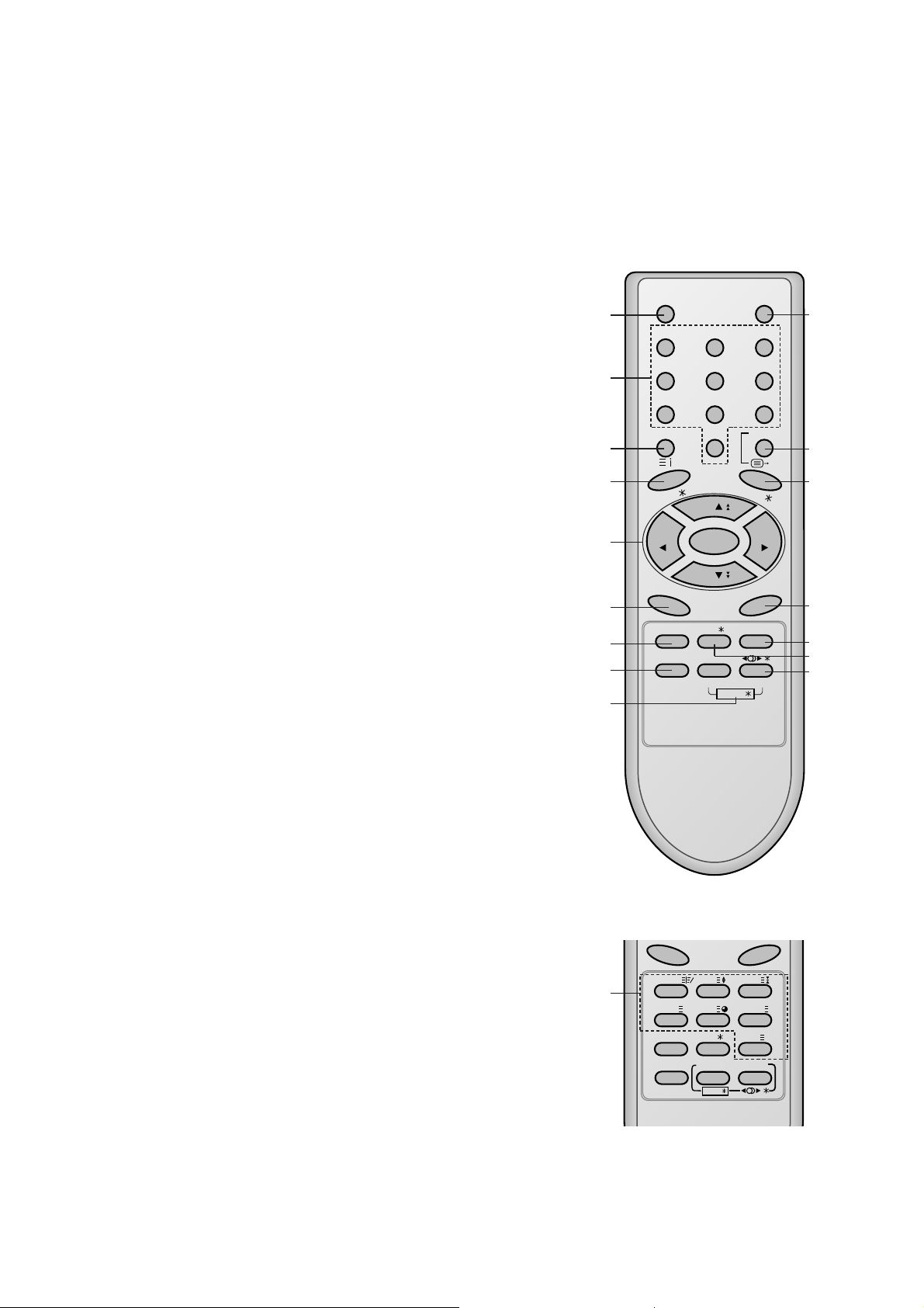
13. I/II/*(option)
selects the language during dual language broadcast. (option)
selects the sound output.
14. LIST
displays the programme table.
15. SLEEP
sets the sleep timer.
16. SSM/
*
(option) (Sound Status Memory)
recalls your preferred sound setting.
17. SURROUND (
ºº
/
*
) (option)
selects surround sound.
18. VCR BUTTONS
control a LG video cassette recorder.
19. PIP BUTTONS (option)
PIP
switches the sub picture on or off.
PR +/-
selects a programme for the sub picture.
SWAP
alternates between main and sub picture.
INPUT
selects the input mode for the sub picture.
SIZE
adjusts the sub picture size.
STILL
freezes motion of the sub picture.
POSITION
relocates the sub picture in clockwise direction.
9/4 PIP
switches on or off the 9 or 4 sub pictures.
*
: No function
COLOURED BUTTONS : These buttons are used for teletext (only
TELETEXT models) or programme edit.
(Without TELETEXT / PIP)
POWER MUTE
123
456
789
MENU/INDEX
TV/AV
0
EYE/
Q.VIEW
LIST
I / II /
( )
PR
( )
PR
OK
VOLVOL
PSM SSM/ SLEEP
PICTURE SOUND
/
TURBO/
FAVOURITE
TV
1
2
3
4
5
6
8
10
11
12
13
14
15
17
16
9
TEXT/MIX/ SIZE/ HOLD/
Q.VIEW
LIST
UPDATE/
PSM SSM/ SLEEP/ M
X
TIME/ REVEAL/
?
PICTURE SOUND
/
TURBO/
FAVOURITE
7
(With TELETEXT / Without PIP)
- 6 -
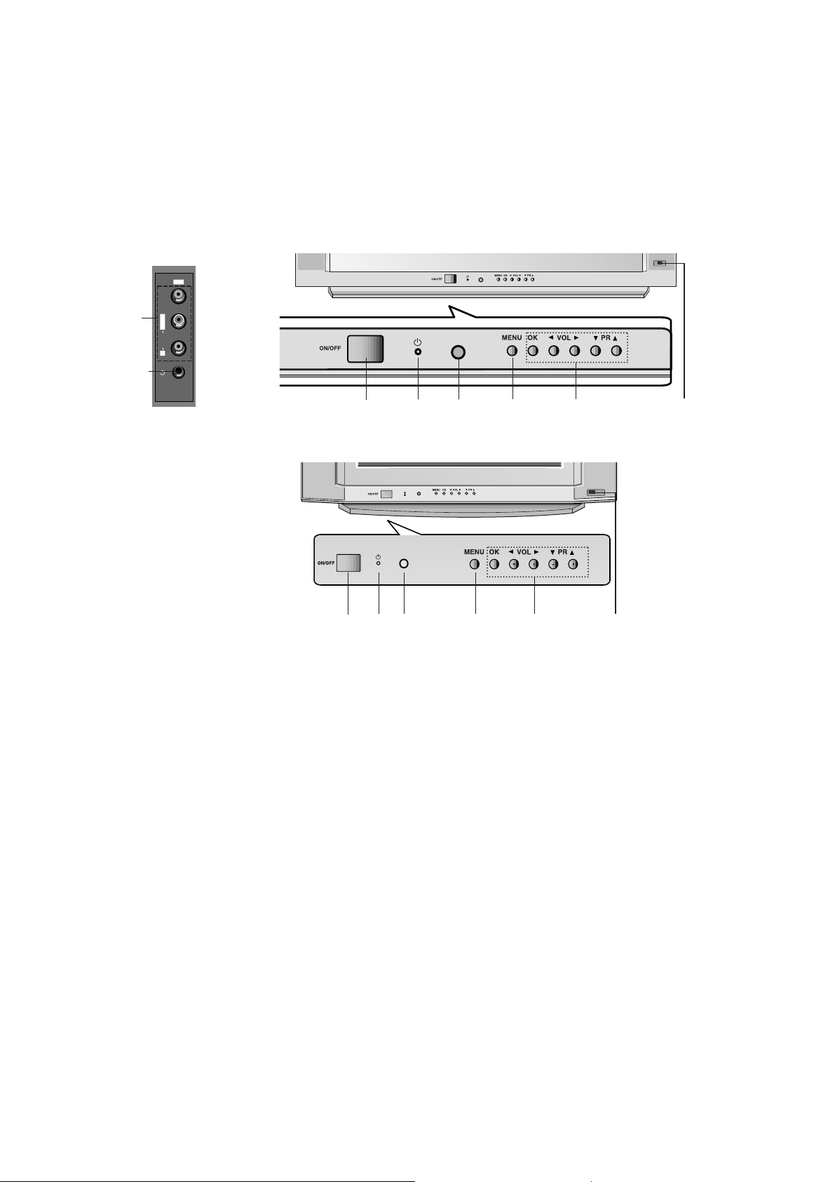
1. MAIN POWER (ON/OFF)
switches the set on or off.
2. POWER/STANDBY INDICATOR
illuminates brightly when the set is in standby
mode.
dims when the set is switched on.
3. REMOTE CONTROL SENSOR
Note : Only use the supplied remote control
handset. (When you use others, they’ll be not
able to function.)
4. MENU
selects a menu.
5. OK
accepts your selection or displays the current
mode.
FF / GG (Volume Up/Down)
adjusts the volume.
adjusts menu settings.
DD / EE
(Programme Up/Down)
selects a programme or a menu item.
switches the set on from standby.
6. AUDIO/VIDEO IN SOCKETS (AV2) (option)
Connect the audio/video out sockets of external equipment to these sockets.
7. HEADPHONE SOCKET (option)
Connect the headphone plug to this socket.
8. EYE (option)
adjusts picture according to the surrounding
conditions.
Note : Shown is a simplified representation of
front or side panel. Here shown may be somewhat different from your set.
21FX4R series
17/21FX5R series
Front panel
Side panel
VIDEO
L/MONO
R
AUDIO
AV2
7
6
1
2 3
4
5
8
1
2 3
4
5
8
- 7 -
SPECIFICATIONS
Note : Specification and others are subject to change without notice for improvement.
V Scope
This specification can be applied to all the television related to
MC-049B Chassis.
V Test and Inspection Method
1) Capacity : Follow LG electronics TV testing Standard.
2) Another Required Standard
- EMI : Following CE Standard (EN55020, EN55013)
- Safety : Following CB Standard (EN55013)
V Requirement for Test
Testing for standard of each par must be followed in below
condition
1) Temperature : 20
± 5°C
(CST must be tested 40
± 5°C . Humidity : 50%)
2) Relative Humidity : 65
± 10%
3) Power : Standard input Voltage (110-240V~, 50/60Hz)
4) Measurement must be performed after heat-run more than
20min.
5) Adjusting Standard for this chassis is followed a special
standard.
No
1
2
3
4
5
6
7
8
Item
Receiving System
Receiving Channel
Input Voltage
Market
Screen Size
Tuning System
Operating Environment
Storage Environment
Remark
For EU/ For Non EU
For EU/ For Non EU
NTSC-M (Multi - model)
Non EU
EU
FLAT / CONVENTIONAL
200 PR. (OPTION)
Specification
1) PAL/SECAM BG
2) PAL/SECAM DK
3) PAL I/I
4) NTSC M
5) SECAM-L/L’
6) NTSC 4.43(AV)
1) VHF : E2 ~ E12
UHF : E21 ~ E69
CATV : S1 ~ S20
HYPER : S21 ~ S41
2) L/L’ : B,C,D
3) VHF : 02 ~ 13
UHF : 14~ 69
CATV : 02 ~ 71
110-240V~, 50/60Hz
240V~, 50Hz
EU,CIS, China, Asia, Africa
14” ~ 21”
FVS 100Program
1) Temp. : 0 ~ 45 deg
2) Humidity: 85% under
1) Temp. : -20 ~ 60 deg
2) Humidity: 85% under
V General Specification
1. Application Object
These instructions are applied to all of the color TV, MC-049B.
2. Notes
(1) Because this is cold chassis, it is not necessary to use an
isolation transformer. However, the use of isolation
transformer will help protect test instrument.
(2) But, operate it using a transformer between the power
supply line and chassis input to prevent electric shock and
to protect the test instrument.
(3) All adjustments must be done in correct sequence.
(4) However, for the better productivity, it can be changed in
pre-permitted range.
(5) Environment conditions : If not specified, it must be done in
following conditions.
1) Temperature : 25±5°C
2) Humidity : 65±10%
(6) Power supply of a SET which is adjusted is (100-240V~)
±10%, 50~60 Hz
(7) If not specified, the receiver must be operated for more
than 20 minutes period to the adjustment.
(8) Signal : Receive the standard color signal (65dB±1dB uV)
LG standard signal means the digital pattern,EU
05 CH(PAL)
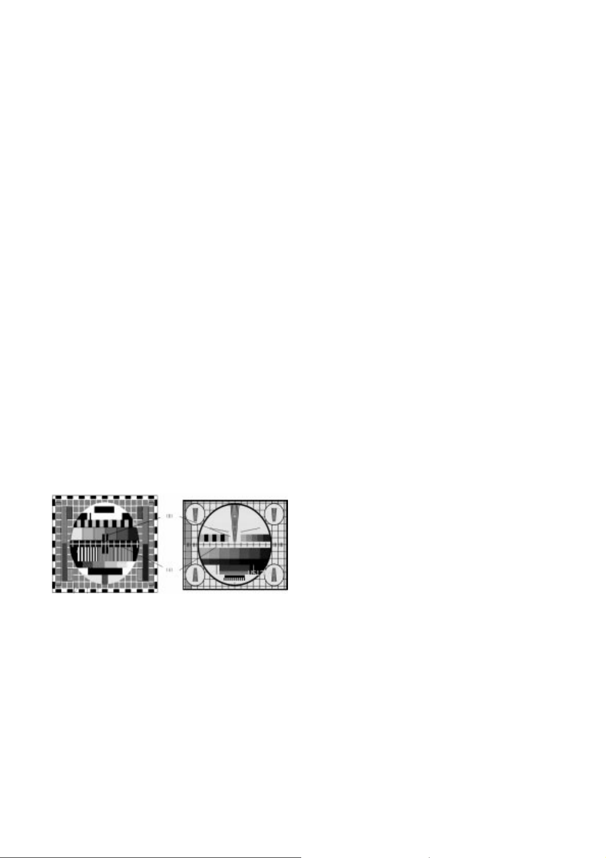
3. Focus voltage adjustment
(1) Receive the LG standard pattern
(digital pattern, PAL : Fig 1 & NTSC : Fig2)
(2) Set the picture condition on ‘STANDARD’ mode.
(3) Adjust the Focus volume of FBT for the best focus of
horizontal line A, vertical line B.
4. Purity & Convergence adjustment
4.1. Purity adjustment
(1) Preparation
1) Receive the RED Raster Pattern for purity adjustment.
(11CH)
2) Demagnetize the CPT and cabinet with a degaussing coil.
(2) Adjustment
1) Pre-adjust the static convergence(STC) with 4 and 6pole magnet.
2) Push the DY all way to the CPT panel.
3) Turn the purity magnet (2-pole magnet) so that the green
portion of left side and the blue portion of right side have
same portion.
4) Pull the DY slowly and fix it when the whole screen
become red.
4.2. Convergence adjustment
(1) Preparation
1) Receive the Cross Hatch pattern for convergence
adjustment. (09CH)
2) Let the contrast at the adequate luminance level.
(2) Adjustment
1) Converge the RED vertical line and BLUE vertical line in
the same line by changing the angle between the 2 tabs
of the 4 pole magnet.
2) Converge the RED horizontal line and BLUE horizontal
line in the same line by turning the 2 tabs of the 4pole
magnet. This time, do not changing the angle between
the 2 tabs.
3) Converge the R,G,B vertical line in the same line by
changing the angle between the 2 tabs of the 6pole
magnet.
4) Converge the R,G,B horizontal line in the same line by
turning the 2 tabs of the 6pole magnet. This time, do not
change the angle between the 2 tabs.
5. Screen voltage & White balance
adjustment
Screen adjustment mode:INSTART for line SVC MODE then
ADJ.
Vary screen volume of the FBT till horizontal line appear and
stop to the point that it starts to disappear.
5-1. Screen voltage adjustment
(1) Receive the PAL or SECAM(NTSC) signal into RF mode
regardless of channel.
(2) If you press the “ADJ”button in LINE SVC mode(IN-START
button),the LINE SVC mode changes to screen adjustment
mode.
(3) Adjust the screen volume of FBT jack,When width line is
seen turn the FBT screen volume at the position of
disappearance it.
(4) Press the TV/AV button to exit SVC mode.
5-2. White balance adjustment
- Prior to this adjustment, the Screen Voltage adjustment must
be finished.
(1) Necessary Instrument
1) Auto White Balance Meter
2) Color Analyzer (CA-100)
3) Factory SVC Remote control
(2) Adjustment
1) Make the picture luminance 35±10 Ft-L by changing the
“CONTRAST” and “BRIGHTNESS”.
- 8 -
ADJUSTMENT INSTRUCTIONS
<Fig 1> <Fig 2>
2) Enter the white balance adjust mode with a factory
remote control.
3) Adjust HIGh Light status of WDR R, WDR B at WDR G.
4) Make the Picture luminance 4.5±1 Ft-L by changing the
‘contrast’ and ‘brightness’.
5) Adjust LOW Light status of CUT R, CUT B at CUT G.
6) Repeat 1) ~ 5) until both low and high have same color
temperature with below.
* Note: When adjusting white balance automatically, connect the
adjustment JIG in SVC mode. (When pressing IN-START,
MUTE button on remote control for adjustment orderly, it
changes to SVC mode and screen displays SVC.)
* White balance auto adjustment- Jig initial setting data
2. White balance IIC Parameter
6. SUB Brightness adjustment
Receiving signal : Digital pattern (PAL : EU05CH)
1) In the LINE SVC MODE(IN-START key), select
SERVICE11 change S-BRI by VOL ± key
2) Change S-BRI data till 2~3 Gray scale of the pattern can
be discerned.
7. Deflection setting Data Adjustment
7.1 preparation
(1) At adjustment mode(IN-START button on remote control of
adjustment), change to LINE SVC 2 mode to adjust the
deflection.
(2) Press Channel UP/DOWN button for desirous function
adjustment.
(3) Press Volume UP/DOWn button to adjust the data
(4) Tune the TV set receive a digital pattern.
7.2 Adjustment
<Note>
First, adjust deflection at 50Hz of PAL signal.
Then, adjust deflection at 60Hz of NTSC signal (RT)
In case of PAL only model, adjust deflection at 50Hz of PAL
signal.
Store the deflection adjustment data in EEPROM by using
ENTER button before adjusting PIP position.
After finishing deflection adjustment, press the ENTER button
to enter or exit PIP position.
(1) VA (Vertical Amplitude)
Adjust so that the circle of a digital circle pattern may be
located within the effective screen of the CPT.
(2) VL(Vertical Linearity)
Adjust so that the boundary line between upper and lower
half is in accord with geometric horizontal center of the
CPT.
(3) SC(S-Correction)
Adjust so that all distance between each horizontal lines
are to be the same.
(4) VS (Vertical Shift)
Adjust so that the horizontal center line of a digital circle
pattern is in accord with geometric horizontal center of the
CPT.
(5) HS(Horizontal Shift)
Adjust so that the vertical center line of a digital circle
pattern is in accord with geometric vertical center of the
CPT.
(6) EW(Horizontal Shift)
Adjust so that a digital circle pattern looks like exact circle.
(7) ET(East-west Trapezium)
Adjust to make the length of top horizontal line same with it
of the bottom horizontal line.
(8) EP(East-west Parabola)
Adjust so that middle portion of the outermost left and right
vertical line looks like parallel with vertical lines of th CPT.
(9) ES(East-west Symmetric)
Adjust until the upper and lower corner of the screen
symmetric.
(10) EC(East-west Corner)
After completing the EP adjustment, adjust so that the
corner vertical line to be straight..
- 9 -
AXIS
X
Y
Color Temperature
288
295
9000°K
266
273
13000°K
EU
N-EU
<Table 1> White Balance Color axis
Menu
CUT R
CUT G
CUT B
WDR R
WDR G
WDR B
LOW LIGHT
HIGH LIGHT
0 ~ 511
0 ~ 511
0 ~ 511
0 ~ 511
0 ~ 511
0 ~ 511
60
60
60
400
400
400
Range
DATA
<Table 2> White Balance Initial Data
<Table 3> White Balance Initial Data
1. IC
VCD IC
EP_ROM
VCT49xyi
24C16
Micronas
ST, ATMEL
0 A 0
Name
Maker Algorithm
Menu
Speed/ Plus 1 1 1 1
Program
Sub Add
Start Bit
Stop Bit
Offset
Polarity
EP_Rom_S
R_Amp
TWBeng_v049
1C8
12
4
0
1
9091
R_Cut
TWBeng_v049
1C3
12
4
0
1
8A8B
B_Amp
TWBeng_v049
1CA
12
4
0
1
9495
Program
Vcd Slave
TWBeng_v049
BCF0
Program
Eprom_Slave
TWBeng_v049ACSpeed1Delay
30
B_Cut
TWBeng_v049
1C5
12
4
0
1
8E8F
 Loading...