

LG 21FU6ALX Manual book

Colour Television
OWNER’S MANUAL
Please read this manual carefully before operating your set.
Retain it for future reference.
Record model number and serial number of the set.
See the label attached on the back cover and quote this information to your dealer when you require service.
Model number :
Serial number :
P/NO : MFL41308405 (CW81A/B, 33981404/06 TX) a

Contents
2
Installation.........................................................2
Connection of external equipment..................3
Location and function of controls...................4
Basic operation.................................................8
On screen menus..............................................8
Setting up TV stations......................................9
Picture adjustment..........................................12
Sound adjustment...........................................13
Time setting.....................................................14
Other functions...............................................15
PIPoperation (option)....................................16
Teletext (option)..............................................17
Troubleshooting check list............................19
Power
This set operates on an AC mains supply, the voltage is as indicated on the label on the back cover.
Never apply DC power to the set. In the event of
thunderstorms or powercuts, please pull out the
aerial and mains plugs.
Warning
To prevent fire or shock hazard, do not expose the
set to rain or moisture.
Do not place anything containing liquid on top of
the set, this may cause a fire or could give an
electric shock.
Service
Never remove the back cover of the set as this
can expose you to very high voltage and other
hazards. If the set does not operate properly,
unplug it and call your dealer.
Aerial
Connect the aerial cable to the socket on the back
cover. For the best reception an outdoor aerial
should be used.
Location
Position your set so that no bright light or sunlight
falls directly onto the screen. Care should be
taken not to expose the set to any unnecessary
vibration, moisture, dust or heat. Also ensure that
the set is placed in a position to allow a free flow
of air. Do not cover the ventilation openings on the
back cover.
Note:
To remove dirt or fingerprint on the surface of your
TV, please rub with a line-free cloth.
Do not pose too much pressure in cleaning so as
to prevent any risk of damage to the product.
Installation

3
Connection of external equipment
You can connect additional equipment, such as
VCRs, camcorders etc. to your set.
What is shown here may
be somewhat different
from your set.
Aerial socket
1. Connect the RF out socket of the VCR to the
aerial socket on the back of the set.
2. Connect the aerial cable to the RF aerial in
socket of the VCR.
3. Store the VCR channel on a desired programme number using the ‘Manual programme tuning’ section.
4. Select the programme number where the
VCR channel is stored.
5. Press the PLAY button on the VCR.
Audio/Video in/out sockets (option)
1. Connect the audio/video out sockets of the
VCR to audio/video in sockets of the set and
in sockets of the VCR to RF OUT sockets of
the set.
2. If the VCR is connected to the AV sockets on
the set, press the TV/AV button to select AV1
or AV2.
3. Press the PLAY button on the VCR.
The VCR playback picture appears on the
screen.
You can also record programmes received by
the TV on video tape via audio/video out sockets.
Note : If you have a mono VCR, connect the
audio cable from the VCR to the AUDIO L/MONO
socket of the set.
Euro scart socket (option)
1. Connect the Euro scart socket of the VCR to
the Euro scart socket of the set.
2. Press the PLAY button on the VCR.
If your VCR outputs a switching voltage when
connected to Euro scart socket, the set will
switch to AV 1 mode automatically. But if you
want to keep on watching TV mode, press the
DD / EE
or NUMBER buttons.
Otherwise press the TV/AV button on the
remote control
handset to select AV 1 The VCR playback pic-
ture appears on the screen.
You can also record programmes received by the
TV on video tape.
Note : Signal type RGB, i.e. the signals red, green
and blue can only be selected for the Euro scart
socket. These signals are transmitted, for example, by a pay TV decoder, game machine or photo
CD unit, etc.
Component in sockets (option)
1. Connect the COMPONENT video output
sockets (Y Cb Cr , YPb Pr or Y B-Y R-Y) of the
COMPONENT (480i) to the COMPONENT
INPUT sockets (Y PB PR) on the set.
2. Connect the audio cable from the COMPONENTto AUDIOINsockets of AV IN.
3. Press the TV/AV button to select COMPO-
NENT
.
4. Press the PLAY button on the COMPONENT.
The COMPONENT playback picture appears
on the screen.
All the functions can be controlled with the remote control handset.
Some functions can also be adjusted with the buttons on the front
panel of the set.
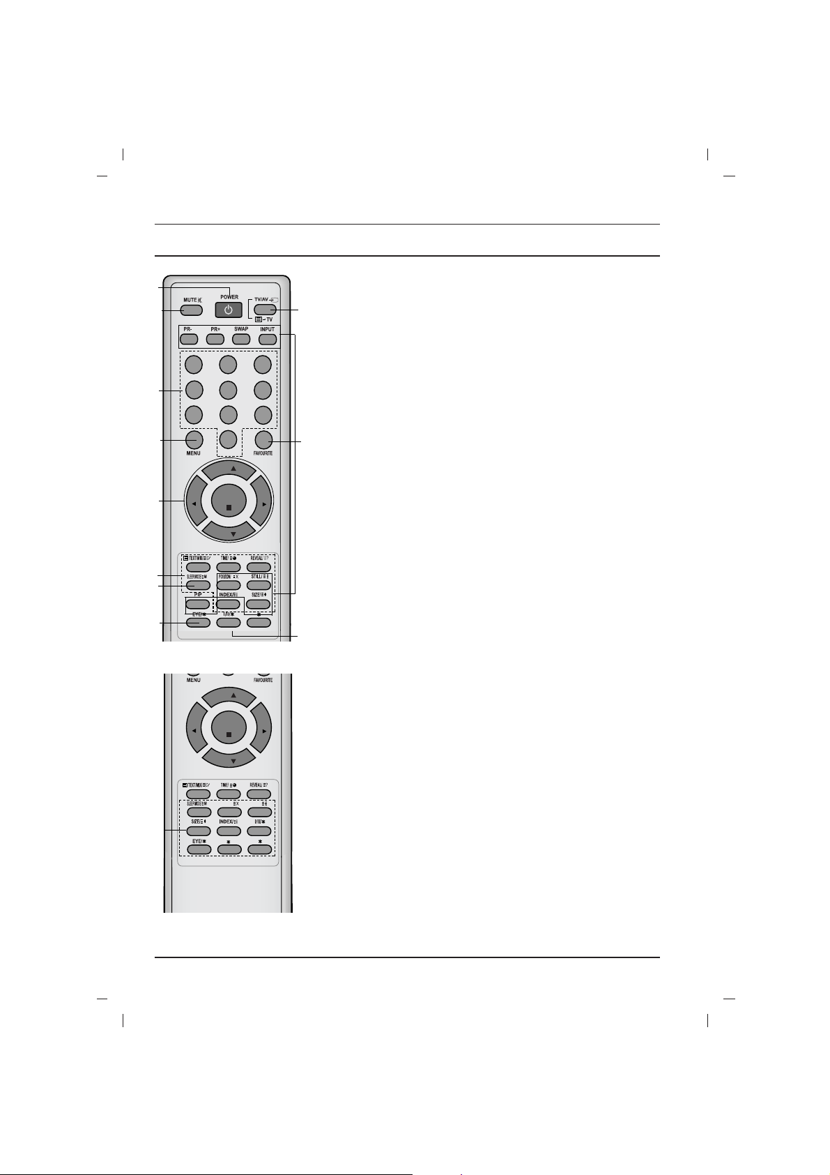
Remote control handset
Before you use the remote control handset, please install the batteries. See the next page.
1. POWER
switches the set on from standby or off to standby.
2. NUMBER BUTTONS
switches the set on from standby or directly select a number.
3. MENU
selects a menu.
4.
DD / EE
(Programme Up/Down)
selects a programme or a menu item.
switches the set on from standby.
scans programmes automatically.
FF / GG
(Volume Up/Down)
adjusts the volume.
adjusts menu settings.
OK
accepts your selection or displays the current mode.
5. TELETEXT BUTTONS (option)
these buttons are used for teletext.
for further details, see the ‘Teletext’ section.
6.
SLEEP
sets the sleep timer.
7. PIP BUTTONS (option)
PIP
switches the sub picture on or off.
PR +/-
selects a programme for the sub picture.
SWAP
alternates between main and sub picture.
INPUT
selects the input mode for the sub picture.
SIZE
adjusts the sub picture size.
STILL
freezes motion of the sub picture.
POSITION
relocates the sub picture in clockwise direction.
(With TELETEXT / PIP)
123
4
5
6
7
8
9
0
PR
PR
VOL
VOL
OK
1
2
3
4
6
5
7
12
8
11
9
10
PR
PR
VOL
VOL
OK
UPDATE/
HOLD/
(With TELETEXT / Without PIP)
5
Location and function of controls
4
Location and function of controls
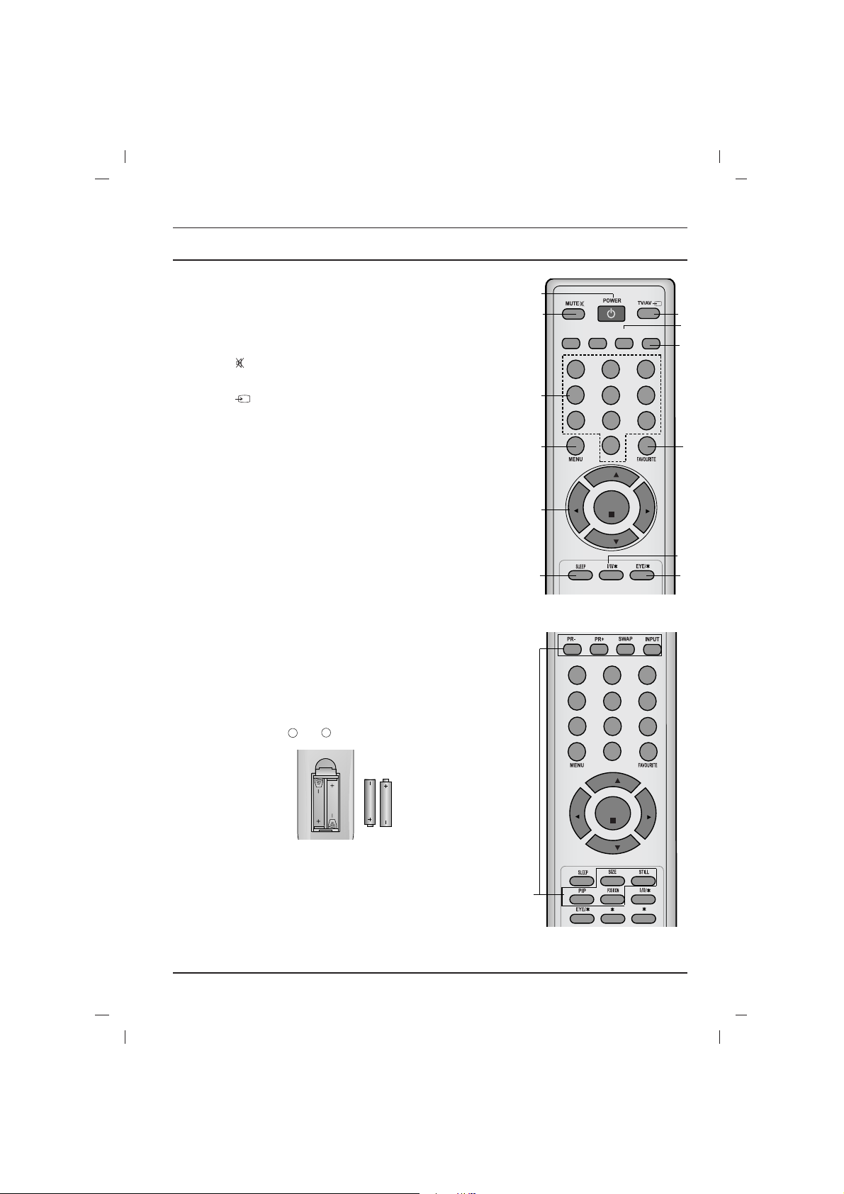
8. FAVOURITE
selects a favourite programme.
9.
EYE/*(option)
switches the eye function on or off.
10. MUTE
switches the sound on or off.
11. TV/AV
selects TV or AV or Component mode.
switches the set on from standby.
exits the Teletext mode.
12.
I/II/
*
selects the language during dual language broadcast.
selects the sound output (option).
13. Q.VIEW (or YELLOW)
returns to the previously viewed programme.
14.
LIST (or BLUE)
displays the programme table.
*
: No function
COLOURED BUTTONS : These buttons are used for teletext (only
TELETEXT models) or programme edit.
Battery installation
The remote control handset is powered by two AAA type batteries.
To load the batteries, turn the remote control handset over and
open the battery compartment. Install two batteries as indicated by
the polarity symbols ( and ) marked inside the compartment.
Note : To avoid damage from possible battery leakage, remove the
batteries if you do not plan to use the remote control handset for an
extended period of time.
+
-
123
4
5
6
7
8
9
0
PR
PR
VOL
VOL
OK
Q.VIEW LIST
(Without TELETEXT / PIP)
123
4
5
6
7
8
9
0
PR
PR
VOL
VOL
OK
(With PIP / Without TELETEXT)
4
1
8
12
13
11
14
6
9
10
7
2
3
5
PR
OK
21FU1 series
1
4
5
2
3
6
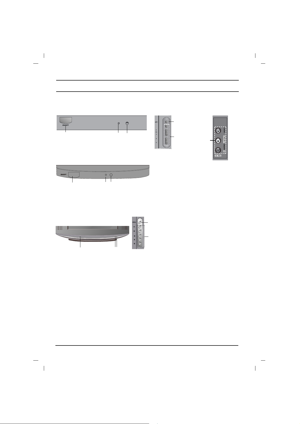
Location and function of controls
Front panel
21FU6 series
21FU3 series
1
2
3
1 23
Side panel
4
5
6
 Loading...