

lg 21FB5RB, 21FB5RG, 21FB5RGE, 21FB5RL, 21FB5RB-TH Service Manual
...
COLOR TV
SERVICE MANUAL
CAUTION
BEFORE SERVICING THE CHASSIS,
READ THE SAFETY PRECAUTIONS IN THIS MANUAL.
CHASSIS : MC-059B
MODEL: 21FB5RB/RG/RGE/RL
MODEL:
21FB5RB/RG/RGE/RL-TH
website:http://biz.LGservice.com
e-mail:http://www.LGEservice.com/techsup.html

- 2 -
CONTENTS
CONTENTS............................................................................................................. 2
SAFETY PRECAUTIONS....................................................................................3
DESCRIPTION OF CONTROLS.......................................................................4
SPECIFICATIONS ..................................................................................................7
ADJUSTMENT........................................................................................................9
PRINTED CIRCUIT BOARD .............................................................................14
BLOCK DIAGRAM...............................................................................................15
TROUBLE SHOOTING.......................................................................................16
EXPLODED VIEW................................................................................................20
EXPLODED VIEW PARTS LIST .....................................................................21
REPLACEMENT PARTS LIST ....................................................................... 22
- 3 -
SAFETY PRECAUTIONS
Many electrical and mechanical parts in this chassis have special safety-related characteristics. These parts are identified by in
the Schematic Diagram and Replacement Parts List.
It is essential that these special safety parts should be replaced with the same components as recommended in this manual to
prevent X-RADIATION, Shock, Fire, or other Hazards.
Do not modify the original design without permission of manufacturer.
General Guidance
An isolation Transformer should always be used during
the servicing of a receiver whose chassis is not isolated from
the AC power line. Use a transformer of adequate power rating
as this protects the technician from accidents resulting in
personal injury from electrical shocks.
It will also protect the receiver and it's components from being
damaged by accidental shorts of the circuitry that may be
inadvertently introduced during the service operation.
If any fuse (or Fusible Resistor) in this TV receiver is blown,
replace it with the specified.
When replacing a high wattage resistor (Oxide Metal Film
Resistor, over 1W), keep the resistor 10mm away from PCB.
Keep wires away from high voltage or high temperature parts.
Due to high vacuum and large surface area of picture tube,
extreme care should be used in handling the Picture Tube.
Do not lift the Picture tube by it's Neck.
X-RAY Radiation
Warning:
To determine the presence of high voltage, use an accurate
high impedance HV meter.
Adjust brightness, color, contrast controls to minimum.
Measure the high voltage.
The meter reading should indicate
23.5
¡ 1.5KV: 14-19 inch, 26 ¡ 1.5KV: 19-21 inch,
29.0 ¡ 1.5KV: 25-29 inch, 30.0 ¡ 1.5KV: 32 inch
If the meter indication is out of tolerance, immediate service
and correction is required to prevent the possibility of
premature component failure.
Before returning the receiver to the customer,
always perform an AC leakage current check on the exposed
metallic parts of the cabinet, such as antennas, terminals, etc.,
to be sure the set is safe to operate without damage of
electrical shock.
Leakage Current Cold Check(Antenna Cold Check)
With the instrument AC plug removed from AC source,
connect an electrical jumper across the two AC plug prongs.
Place the AC switch in the on position, connect one lead of
ohm-meter to the AC plug prongs tied together and touch other
ohm-meter lead in turn to each exposed metallic parts such as
antenna terminals, phone jacks, etc.
If the exposed metallic part has a return path to the chassis, the
measured resistance should be between 1MΩ and 5.2MΩ.
When the exposed metal has no return path to the chassis the
reading must be infinite.
An other abnormality exists that must be corrected before the
receiver is returned to the customer.
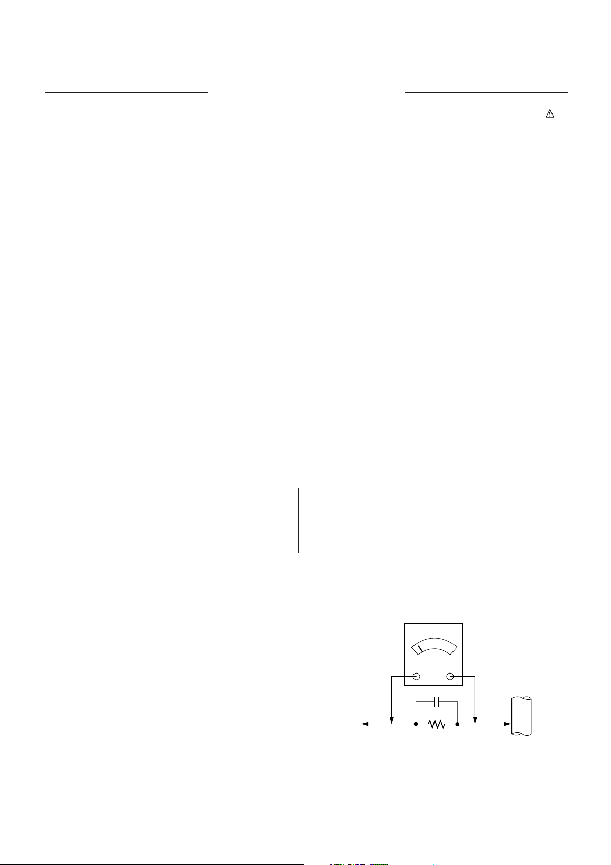
Leakage Current Hot Check (See below Figure)
Plug the AC cord directly into the AC outlet.
Do not use a line Isolation Transformer during this check.
Connect 1.5K/10watt resistor in parallel with a 0.15uF capacitor
between a known good earth ground (Water Pipe, Conduit, etc.)
and the exposed metallic parts.
Measure the AC voltage across the resistor using AC
voltmeter with 1000 ohms/volt or more sensitivity.
Reverse plug the AC cord into the AC outlet and repeat AC
voltage measurements for each exposed metallic part. Any
voltage measured must not exceed 0.75 volt RMS which is
corresponds to 0.5mA.
In case any measurement is out of the limits specified, there is
possibility of shock hazard and the set must be checked and
repaired before it is returned to the customer.
Leakage Current Hot Check circuit
The source of X-RAY RADIATION in this TV receiver is the
High Voltage Section and the Picture Tube.
For continued X-RAY RADIATION protection, the
replacement tube must be the same type tube as specified in
the Replacement Parts List.
1.5 Kohm/10W
To Instrument’s
exposed
METALLIC PARTS
Good Earth Ground
such as WATER PIPE,
CONDUIT etc.
AC Volt-meter
IMPORTANT SAFETY NOTICE
0.15uF
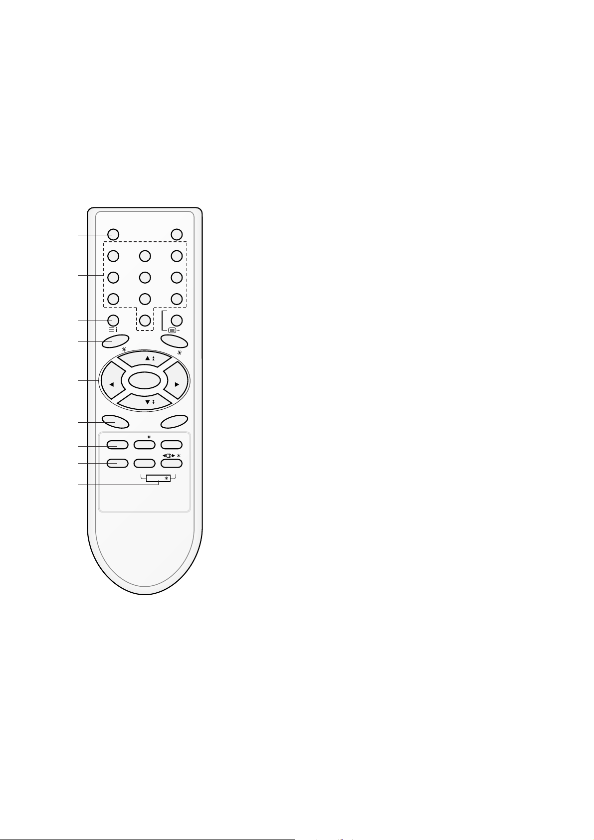
All the functions can be controlled with the remote control handset.
Some functions can also be adjusted with the buttons on the front
panel of the set.
Remote control handset
Before you use the remote control handset, please install the batteries. See the next page.
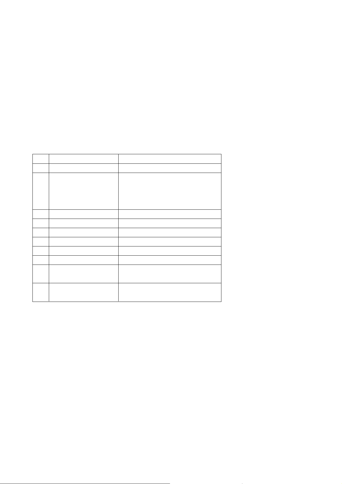
1. POWER
switches the set on from standby or off to standby.
2. NUMBER BUTTONS
switches the set on from standby or directly select a number.
3. MENU (or INDEX)
selects a menu.
selects an index page in the teletext mode (only TELETEXT
models). (option)
4. EYE/
*
(option)
switches the eye function on or off.
5.
DD/ EE
(Programme Up/Down)
selects a programme or a menu item.
switches the set on from standby.
scans programmes automatically.
FF / GG
(Volume Up/Down)
adjusts the volume.
adjusts menu settings.
OK
accepts your selection or displays the current mode.
6. Q.VIEW
returns to the previously viewed programme.
7. PSM (Picture Status Memory)
recalls your preferred picture setting.
8. FAVOURITE
selects a favorite programme.
9. TURBO PICTURE / SOUND BUTTON (option)
selects Turbo picture and sound.
POWER MUTE
123
456
789
MENU/INDEX
TV/AV
0
EYE/
Q.VIEW
LIST
I / II /
( )
PR
( )
PR
OK
VOLVOL
PSM SSM/ SLEEP
PICTURE SOUND
/
TURBO/
FAVOURITE
TV
1
2
3
4
5
6
7
9
8
- 4 -
DESCRIPTION OF CONTROLS
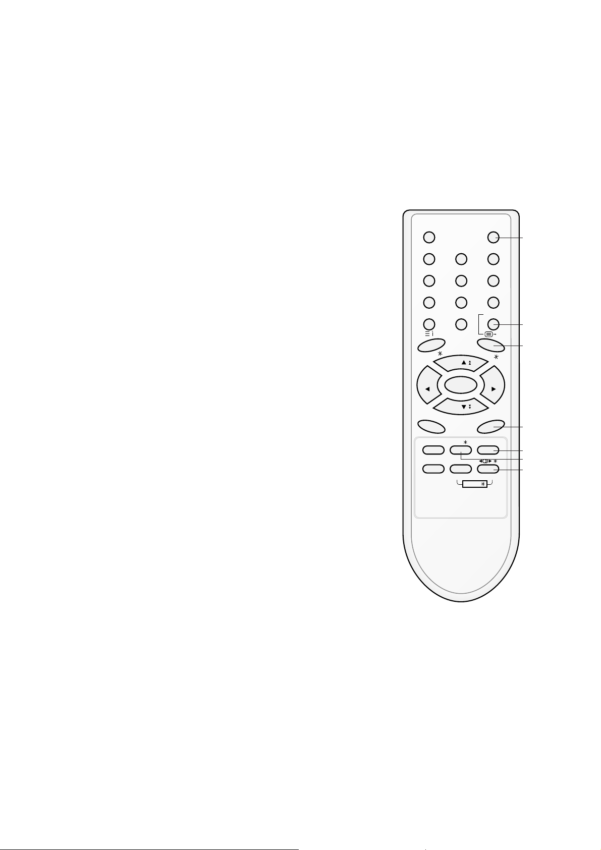
- 5 -
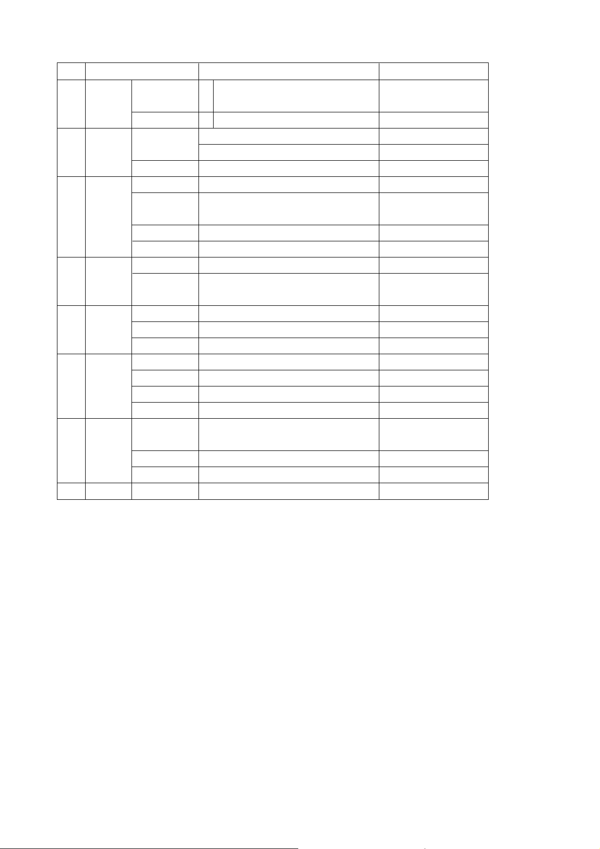
10. MUTE
switches the sound on or off.
11. TV/AV
selects TV or AV mode.
switches the set on from standby.
12. I/II/
*
(option)
selects the language during dual language broadcast. (option)
selects the sound output.
13. LIST
displays the programme table.
14. SLEEP
sets the sleep timer.
15. SSM/
*
(Sound Status Memory) (option)
recalls your preferred sound setting.
16. SURROUND (ºº/
*
) (option)
selects surround sound.
*
: No function
COLOURED BUTTONS : These buttons are used for teletext (only
TELETEXT models) or programme edit.
POWER MUTE
1 2 3
4 5 6
7 8 9
MENU/INDEX
TV/AV
0
EYE/
Q.VIEW
LIST
I / II /
( )
PR
( )
PR
OK
VOLVOL
PSM SSM/ SLEEP
PICTURE SOUND
/
TURBO/
FAVOURITE
TV
10
11
12
13
14
16
15
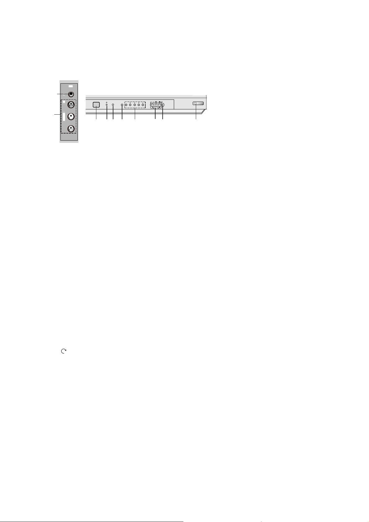
- 6 -
Front panel
1. MAIN POWER (ON/OFF)
switches the set on or off.
2. POWER/STANDBY INDICATOR
illuminates brightly when the set is in standby mode.
dims when the set is switched on.
3. REMOTE CONTROL SENSOR
Note : Only use the supplied remote control handset. (When you use others, they’ll be not able to
function.)
4. MENU
selects a menu.
5. OK
accepts your selection or displays the current mode.
FF / GG
(Volume Up/Down)
adjusts the volume.
adjusts menu settings.
DD / EE
(Programme Up/Down)
selects a programme or a menu item.
switches the set on from standby.
6. AUDIO/VIDEO IN SOCKETS (AV2) (option)
Connect the audio/video out sockets of external equipment to these sockets.
7. HEADPHONE SOCKET (option)
Connect the headphone plug to this socket.
8. EYE (option)
adjusts picture according to the surrounding conditions.
9.
TV/AV (option)
selects TV or AV mode.
clears the menu from the screen.
switches the set on from standby.
10. (Function) (option)
selects volume, EYE (option), picture items or brief auto programme while the menus not display.
11. + / - (
DD / EE
) (option)
adjusts the function or selects a programme.
switches the set on from standby.
12. TURBO SOUND / PICTURE (option)
switches Turbo sound or Turbo picture function on or off.
Note :
a. Do not place any heavy objects (over 4Kg) on the RF/RT-21FA35 series models.
b. Shown is a simplified representation of front or side panel. Here shown may be somewhat different
from your set.
ON/OFF
MENU
OK
VOL PR
VIDEO
AUDIO
L
R
AV
2 3 4 75
1
8
VIDEO
L/MONO
RAUDIO
AV2
7
6
6
V Scope
This specification can be applied to all the television related to
MC-059A Chassis.
V Requirement for Test
Each part is tested as below without special appointment.
1) Temperature : 25 ± 5°C (77 ± 9°F), CST : 40 ± 5
(CST must be tested 40
± 5°C . Humidity : 50%)
2) Relative Humidity : 65
± 10%
3) Power Voltage : Standard input Voltage (110-240V~,
50/60Hz)
* Standard Voltage of each products is marked by models.
4) Specification and performance of each parts are followed
each drawing and specification by part number in
accordance with BOM.
5) The receiver must be operated for about 20 minutes prior to
the adjustment.
V Test Method
1) Performance : LGE TV test method followed.
2) Demanded other specification
- CCC
- Safety : IEC60065
- 7 -
A General specification
SPECIFICATIONS
Note : Specification and others are subject to change without notice for improvement.
Item
Receiving System
Available Channel
Input Voltage
Market
Screen Size
Aspect Ratio
Display Method
Tuning System
Operating Environment
Storage Environment
Specification
PAL BG, DK, I / NTSC M (AV 3.58/ 4.43)
VHF : E2 ~ E12
UHF : E21 ~ E69
CATV : S1 ~ S20
HYPER : S21 ~ S41
100 - 240V~, 50/60Hz
China, Indonesia, Thai, Vietnam, CIS
14 ~ 21inch (FLAT / Conventional)
4:3
CRT
FVS
Temp : 0 ~ 40 deg
Humidity : ~ 85 %
Temp : -20 ~ 60 deg
Humidity : ~ 90 %
No.
1
2
3
4
5
6
7
8
9
10
- 8 -
A Features and Function
Item
Feature AV Input
AV Output
Earphone
Key Local Key
Remocon
Channel Auto prog.
Manual
Prog. edit
Favorite
Picture PSM
User Control
Sound SSM
Treble/ Bass
Equalizer
Timer Clock
Off time
On time
Auto off
Special Language
Input
Child lock
Etc. Sleep
Specification
2 AV 1, 2
1 Monitor out
1 Front
Power, Vol(
F, G), PR(E, D), MENU, OK
Turbo-Picture, Sound
LG Code (NEC)
System/ Storage/ Normal/ Turbo
Storage/ System/ Channel/ Fine/
Search/ Name
Copy/ Move/ Delete/ Skip
8 Channel
Dynamic/ Standard/ Mild/ Game/ User
Contrast/ Brightness/ Color/ Sharpness
Tint (NTSC-M Only)
Flat/ Music/ Movie/ Speech/ User
0 ~ 100
100/ 400/ 1K/ 4K/ 10K
-- : --
-- : -- Off(On)
-- : -- Pr 1 VOL 30 Off(On)
On/ Off
English/ Russia
English/ Indonesia/ Thai/ Vietnam
TV/ AV1/ AV2
On/ Off
Remark
Rear1, Front1(CVBS,L,R)
Rear
7EA/ Front
Option
CIS
East-Asia
No.
1
2
3
4
5
6
7
8

1. Scope of Application
These instructions are applied to MC-059B Chassis.
2. Notes
1) Because this is a cold chassis, it is not necessary to use an
isolation transformer. However, operating it using a
transformer between the power supply line and chassis
input to prevent electric shock and to protect the test
instrument.
2) Adjustment must be done in the correct order.
3) The adjustment must be performed in the circumstance of
25 ± 5°C of temperature and 65 ± 10% of relative humidity
if there is no specific designation.
4) The input voltage of the receiver must keep (100-240~ ±
10%, 50/60Hz) in adjusting
5) The receiver must be operated for about 15 minutes prior to
the adjustment. But adjusting on the board can be done in
jig state right away.
6) Signal: The standard color signal is approved in 65±1dBuV.
3. AGC Voltage Adjustment
3-1. Necessary Instrument
Digital Multi meter : 1 set
- Max Input Current : Over 1A/ Max Input Voltage : 500Vdc
- Measurement Range : 10mV-100mVdc/ Accuracy : 0.03%
3-2. Adjustment Preparation
1) Input LG standard signal into 75Ω antenna terminal (or
PAL-B/G 05CH)
2) Connect the digital multi-meter to terminal(with Hole/
J105) with AGC Check.
3-3. Adjustment
1) Select the VP 0(RF AGC) adjustment mode by pressing
IN-START key on the SVC remote control.
2) After select the RF AGC using CH +/- key, adjust the
multi-meter voltage to be as shown below.
- 6700MF0014A(LG INNOTEK): 2.3±0.05V, 65dBu,
TAEW-G013D
- 6700PF0006B(SANYO): 2.3±0.05V, 65dBu,
115-B-A86EL
3) CAUTION
: Since the signal strength can be easily changed by the
condition of signal cable, you need to check the signal
strength frequently in order to prevent error.
4. Screen Voltage Adjustment
4-1. Adjustment of Screen Manually
(Using SVC Remote Control)
1) Receive the PAL(SECAM) signal into RF mode
regardless of channel.
2) If you press the “ADJ’ key on LINE SVC remote control,
changes to screen adjustment mode.
3) Adjust the Screen Vol. of FBT to appear Horizontal Line
and adjust the Screen Vol. of FBT at disappear point
Horizontal Line.(Press the Enter(
A) key to exit SVC
mode)
5. Purity and Convergence Adjustment
5-1. Purity Adjustment
(1) Adjustment Preparation
1) Receive Red Raster Pattern for purity adjustment.
2) Demagnetize the CPT and Cabinet with a degaussing
coil.
(2) Horizontal Line Adjustment
1) Pre-adjust the static convergence (STC) with the 4 and
6pole magnet.
2) Check if the beam land at mask hole by setting two 2pole magnets in opposite direction respectively.
3) If not, adjust 2-pole magnet so the beam as to land at
mask hole accurately.
(3) Purity Adjustment
1) Adhere DY closely to CPT.
2) Receive Red Pattern and adjust the 2-Pole magnet so
Red color Bar as to locate center and make the portion
of Green color and Blue color same.<Fig.1>
3) Make the full screen Red by pulling DY back slowly.
(When adhering DY, use the electric driver of which
turning force is lower than 10Kg/Cm) <Fig. 2>
5-2. Convergency Adjustment
(1) Necessary Instrument
1) Degaussing Coil
2) Convergency fixing instrument
(2) Preliminary steps
1) Heat run over 30 minutes before adjustment.
2) Demagnetize the CPT and Cabinet by using degaussing
coil.
3) Receive Cross Hatch Pattern.(EU09CH)
4) Adjust Contrast and Brightness for easy observation.
(3) Static Convergence (STC) Adjustment
1) Receive Cross Hatch Pattern(EU09CH)
2) Adjust the focus first seeing to it that the WHITE color
picture quality is sharp enough.
3) Open two 4-Pole magnets until vertical Red and Blue
lines are unified.
4) Rotate the 4-Pole magnets keeping the angle between
two 4-Pole magnets until horizontal Red and Blue lines
are unified.
5) Open two 6-Pole magnets until vertical Red and Green
lines are unified.
6) Rotate the 6-Pole magnets keeping the angle between
two 4-Pole magnets until horizontal Red and Blue lines
are unified.
G R B
- 9 -
ADJUSTMENT
G R B
R
G R B
<Fig. 1>
<Fig. 2>
 Loading...