

Page 1

COLOR TV
SERVICE MANUAL
CAUTION
BEFORE SERVICING THE CHASSIS,
READ THE SAFETY PRECAUTIONS IN THIS MANUAL.
CHASSIS : MC-059B
MODEL: 21FB5RB/RG/RGE/RL
MODEL:
21FB5RB/RG/RGE/RL-TH
website:http://biz.LGservice.com
e-mail:http://www.LGEservice.com/techsup.html
Page 2

- 2 -
CONTENTS
CONTENTS............................................................................................................. 2
SAFETY PRECAUTIONS....................................................................................3
DESCRIPTION OF CONTROLS.......................................................................4
SPECIFICATIONS ..................................................................................................7
ADJUSTMENT........................................................................................................9
PRINTED CIRCUIT BOARD .............................................................................14
BLOCK DIAGRAM...............................................................................................15
TROUBLE SHOOTING.......................................................................................16
EXPLODED VIEW................................................................................................20
EXPLODED VIEW PARTS LIST .....................................................................21
REPLACEMENT PARTS LIST ....................................................................... 22
Page 3
- 3 -
SAFETY PRECAUTIONS
Many electrical and mechanical parts in this chassis have special safety-related characteristics. These parts are identified by in
the Schematic Diagram and Replacement Parts List.
It is essential that these special safety parts should be replaced with the same components as recommended in this manual to
prevent X-RADIATION, Shock, Fire, or other Hazards.
Do not modify the original design without permission of manufacturer.
General Guidance
An isolation Transformer should always be used during
the servicing of a receiver whose chassis is not isolated from
the AC power line. Use a transformer of adequate power rating
as this protects the technician from accidents resulting in
personal injury from electrical shocks.
It will also protect the receiver and it's components from being
damaged by accidental shorts of the circuitry that may be
inadvertently introduced during the service operation.
If any fuse (or Fusible Resistor) in this TV receiver is blown,
replace it with the specified.
When replacing a high wattage resistor (Oxide Metal Film
Resistor, over 1W), keep the resistor 10mm away from PCB.
Keep wires away from high voltage or high temperature parts.
Due to high vacuum and large surface area of picture tube,
extreme care should be used in handling the Picture Tube.
Do not lift the Picture tube by it's Neck.
X-RAY Radiation
Warning:
To determine the presence of high voltage, use an accurate
high impedance HV meter.
Adjust brightness, color, contrast controls to minimum.
Measure the high voltage.
The meter reading should indicate
23.5
¡ 1.5KV: 14-19 inch, 26 ¡ 1.5KV: 19-21 inch,
29.0 ¡ 1.5KV: 25-29 inch, 30.0 ¡ 1.5KV: 32 inch
If the meter indication is out of tolerance, immediate service
and correction is required to prevent the possibility of
premature component failure.
Before returning the receiver to the customer,
always perform an AC leakage current check on the exposed
metallic parts of the cabinet, such as antennas, terminals, etc.,
to be sure the set is safe to operate without damage of
electrical shock.
Leakage Current Cold Check(Antenna Cold Check)
With the instrument AC plug removed from AC source,
connect an electrical jumper across the two AC plug prongs.
Place the AC switch in the on position, connect one lead of
ohm-meter to the AC plug prongs tied together and touch other
ohm-meter lead in turn to each exposed metallic parts such as
antenna terminals, phone jacks, etc.
If the exposed metallic part has a return path to the chassis, the
measured resistance should be between 1MΩ and 5.2MΩ.
When the exposed metal has no return path to the chassis the
reading must be infinite.
An other abnormality exists that must be corrected before the
receiver is returned to the customer.
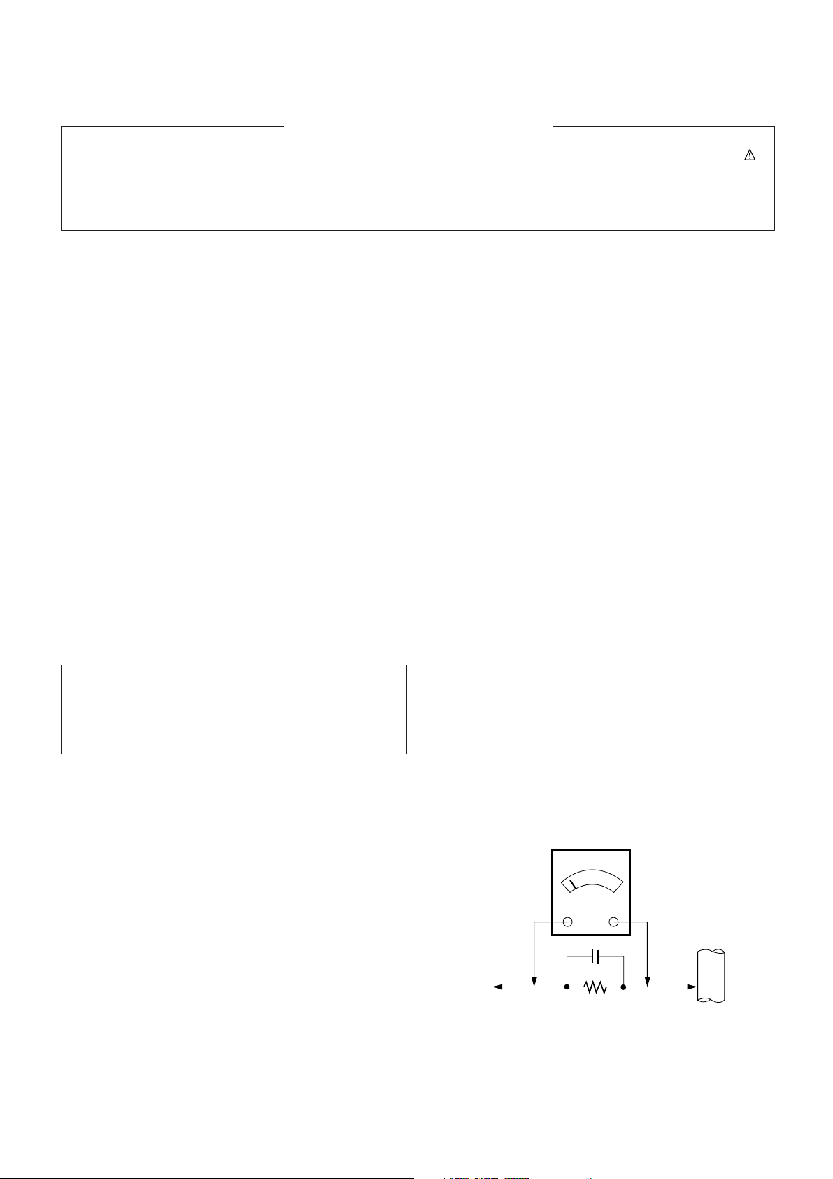
Leakage Current Hot Check (See below Figure)
Plug the AC cord directly into the AC outlet.
Do not use a line Isolation Transformer during this check.
Connect 1.5K/10watt resistor in parallel with a 0.15uF capacitor
between a known good earth ground (Water Pipe, Conduit, etc.)
and the exposed metallic parts.
Measure the AC voltage across the resistor using AC
voltmeter with 1000 ohms/volt or more sensitivity.
Reverse plug the AC cord into the AC outlet and repeat AC
voltage measurements for each exposed metallic part. Any
voltage measured must not exceed 0.75 volt RMS which is
corresponds to 0.5mA.
In case any measurement is out of the limits specified, there is
possibility of shock hazard and the set must be checked and
repaired before it is returned to the customer.
Leakage Current Hot Check circuit
The source of X-RAY RADIATION in this TV receiver is the
High Voltage Section and the Picture Tube.
For continued X-RAY RADIATION protection, the
replacement tube must be the same type tube as specified in
the Replacement Parts List.
1.5 Kohm/10W
To Instrument’s
exposed
METALLIC PARTS
Good Earth Ground
such as WATER PIPE,
CONDUIT etc.
AC Volt-meter
IMPORTANT SAFETY NOTICE
0.15uF
Page 4
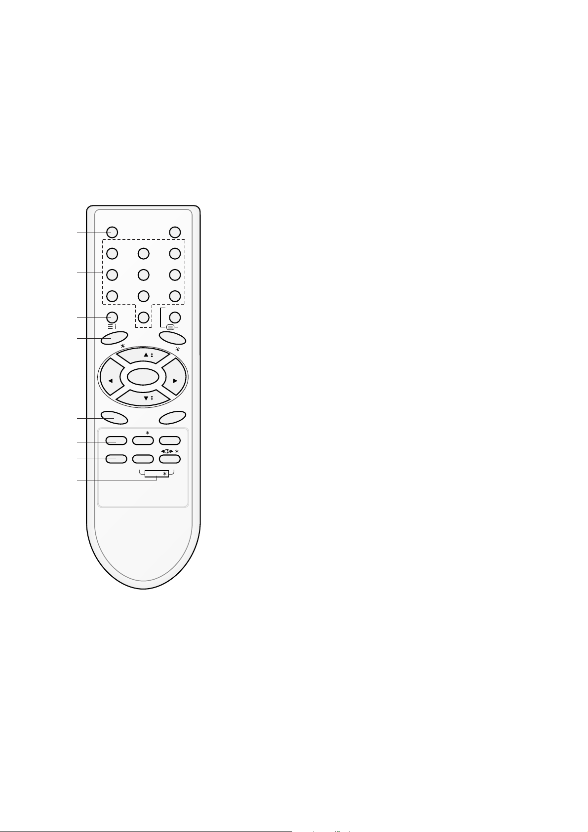
All the functions can be controlled with the remote control handset.
Some functions can also be adjusted with the buttons on the front
panel of the set.
Remote control handset
Before you use the remote control handset, please install the batteries. See the next page.
1. POWER
switches the set on from standby or off to standby.
2. NUMBER BUTTONS
switches the set on from standby or directly select a number.
3. MENU (or INDEX)
selects a menu.
selects an index page in the teletext mode (only TELETEXT
models). (option)
4. EYE/
*
(option)
switches the eye function on or off.
5.
DD/ EE
(Programme Up/Down)
selects a programme or a menu item.
switches the set on from standby.
scans programmes automatically.
FF / GG
(Volume Up/Down)
adjusts the volume.
adjusts menu settings.
OK
accepts your selection or displays the current mode.
6. Q.VIEW
returns to the previously viewed programme.
7. PSM (Picture Status Memory)
recalls your preferred picture setting.
8. FAVOURITE
selects a favorite programme.
9. TURBO PICTURE / SOUND BUTTON (option)
selects Turbo picture and sound.
POWER MUTE
123
456
789
MENU/INDEX
TV/AV
0
EYE/
Q.VIEW
LIST
I / II /
( )
PR
( )
PR
OK
VOLVOL
PSM SSM/ SLEEP
PICTURE SOUND
/
TURBO/
FAVOURITE
TV
1
2
3
4
5
6
7
9
8
- 4 -
DESCRIPTION OF CONTROLS
Page 5
- 5 -
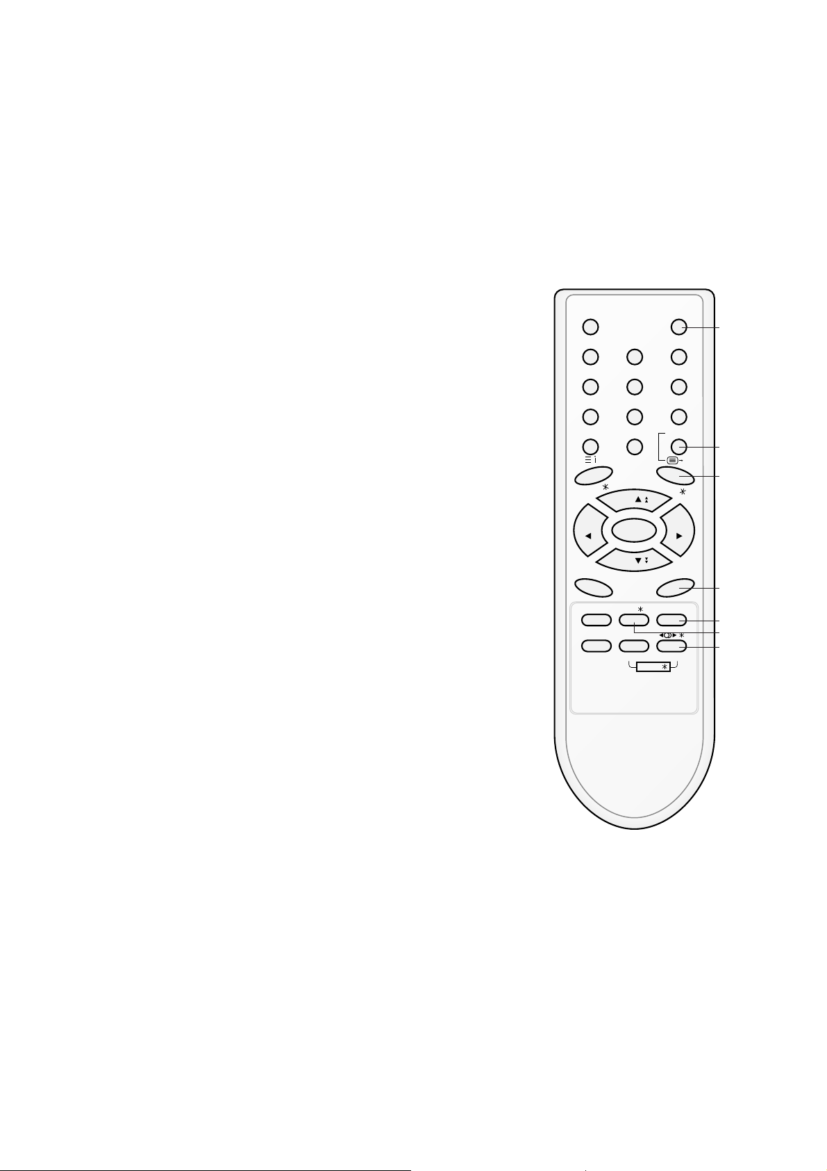
10. MUTE
switches the sound on or off.
11. TV/AV
selects TV or AV mode.
switches the set on from standby.
12. I/II/
*
(option)
selects the language during dual language broadcast. (option)
selects the sound output.
13. LIST
displays the programme table.
14. SLEEP
sets the sleep timer.
15. SSM/
*
(Sound Status Memory) (option)
recalls your preferred sound setting.
16. SURROUND (ºº/
*
) (option)
selects surround sound.
*
: No function
COLOURED BUTTONS : These buttons are used for teletext (only
TELETEXT models) or programme edit.
POWER MUTE
1 2 3
4 5 6
7 8 9
MENU/INDEX
TV/AV
0
EYE/
Q.VIEW
LIST
I / II /
( )
PR
( )
PR
OK
VOLVOL
PSM SSM/ SLEEP
PICTURE SOUND
/
TURBO/
FAVOURITE
TV
10
11
12
13
14
16
15
Page 6
- 6 -
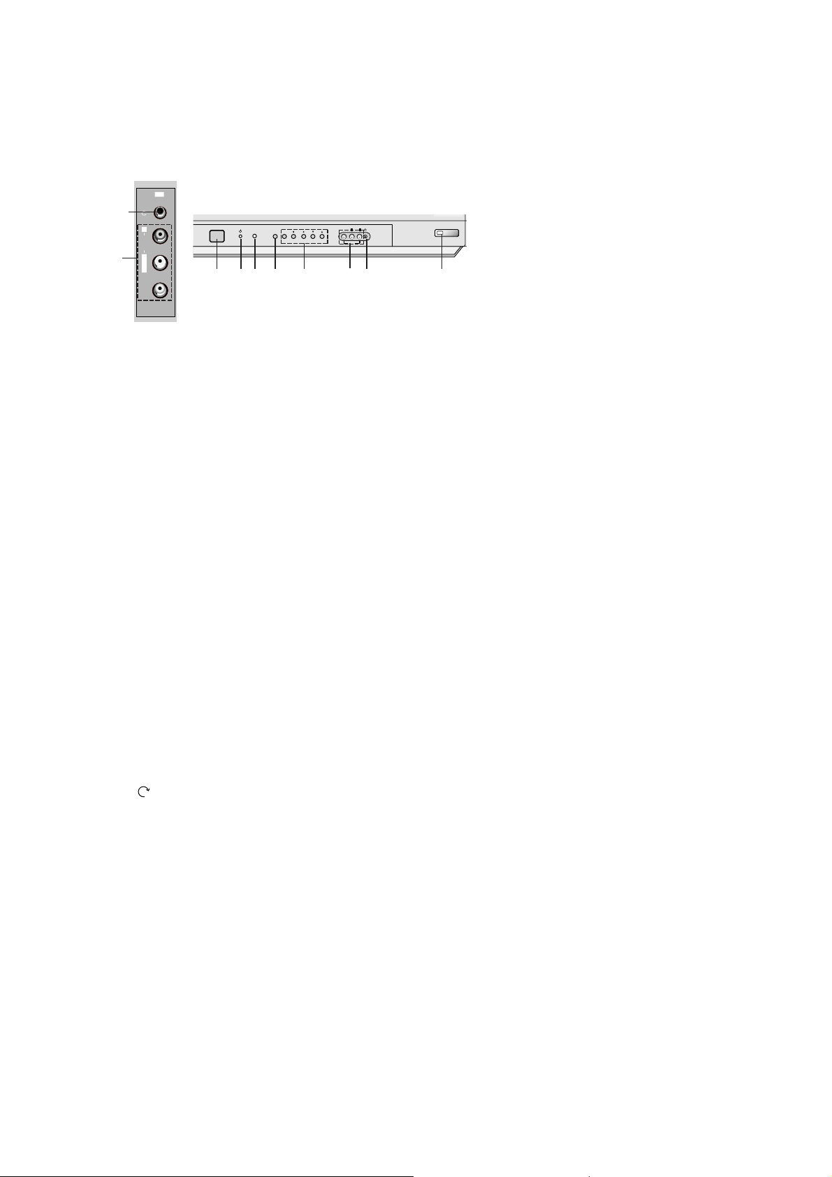
Front panel
1. MAIN POWER (ON/OFF)
switches the set on or off.
2. POWER/STANDBY INDICATOR
illuminates brightly when the set is in standby mode.
dims when the set is switched on.
3. REMOTE CONTROL SENSOR
Note : Only use the supplied remote control handset. (When you use others, they’ll be not able to
function.)
4. MENU
selects a menu.
5. OK
accepts your selection or displays the current mode.
FF / GG
(Volume Up/Down)
adjusts the volume.
adjusts menu settings.
DD / EE
(Programme Up/Down)
selects a programme or a menu item.
switches the set on from standby.
6. AUDIO/VIDEO IN SOCKETS (AV2) (option)
Connect the audio/video out sockets of external equipment to these sockets.
7. HEADPHONE SOCKET (option)
Connect the headphone plug to this socket.
8. EYE (option)
adjusts picture according to the surrounding conditions.
9.
TV/AV (option)
selects TV or AV mode.
clears the menu from the screen.
switches the set on from standby.
10. (Function) (option)
selects volume, EYE (option), picture items or brief auto programme while the menus not display.
11. + / - (
DD / EE
) (option)
adjusts the function or selects a programme.
switches the set on from standby.
12. TURBO SOUND / PICTURE (option)
switches Turbo sound or Turbo picture function on or off.
Note :
a. Do not place any heavy objects (over 4Kg) on the RF/RT-21FA35 series models.
b. Shown is a simplified representation of front or side panel. Here shown may be somewhat different
from your set.
ON/OFF
MENU
OK
VOL PR
VIDEO
AUDIO
L
R
AV
2 3 4 75
1
8
VIDEO
L/MONO
RAUDIO
AV2
7
6
6
Page 7
V Scope
This specification can be applied to all the television related to
MC-059A Chassis.
V Requirement for Test
Each part is tested as below without special appointment.
1) Temperature : 25 ± 5°C (77 ± 9°F), CST : 40 ± 5
(CST must be tested 40
± 5°C . Humidity : 50%)
2) Relative Humidity : 65
± 10%
3) Power Voltage : Standard input Voltage (110-240V~,
50/60Hz)
* Standard Voltage of each products is marked by models.
4) Specification and performance of each parts are followed
each drawing and specification by part number in
accordance with BOM.
5) The receiver must be operated for about 20 minutes prior to
the adjustment.
V Test Method
1) Performance : LGE TV test method followed.
2) Demanded other specification
- CCC
- Safety : IEC60065
- 7 -
A General specification
SPECIFICATIONS
Note : Specification and others are subject to change without notice for improvement.
Item
Receiving System
Available Channel
Input Voltage
Market
Screen Size
Aspect Ratio
Display Method
Tuning System
Operating Environment
Storage Environment
Specification
PAL BG, DK, I / NTSC M (AV 3.58/ 4.43)
VHF : E2 ~ E12
UHF : E21 ~ E69
CATV : S1 ~ S20
HYPER : S21 ~ S41
100 - 240V~, 50/60Hz
China, Indonesia, Thai, Vietnam, CIS
14 ~ 21inch (FLAT / Conventional)
4:3
CRT
FVS
Temp : 0 ~ 40 deg
Humidity : ~ 85 %
Temp : -20 ~ 60 deg
Humidity : ~ 90 %
No.
1
2
3
4
5
6
7
8
9
10
Page 8
- 8 -
A Features and Function
Item
Feature AV Input
AV Output
Earphone
Key Local Key
Remocon
Channel Auto prog.
Manual
Prog. edit
Favorite
Picture PSM
User Control
Sound SSM
Treble/ Bass
Equalizer
Timer Clock
Off time
On time
Auto off
Special Language
Input
Child lock
Etc. Sleep
Specification
2 AV 1, 2
1 Monitor out
1 Front
Power, Vol(
F, G), PR(E, D), MENU, OK
Turbo-Picture, Sound
LG Code (NEC)
System/ Storage/ Normal/ Turbo
Storage/ System/ Channel/ Fine/
Search/ Name
Copy/ Move/ Delete/ Skip
8 Channel
Dynamic/ Standard/ Mild/ Game/ User
Contrast/ Brightness/ Color/ Sharpness
Tint (NTSC-M Only)
Flat/ Music/ Movie/ Speech/ User
0 ~ 100
100/ 400/ 1K/ 4K/ 10K
-- : --
-- : -- Off(On)
-- : -- Pr 1 VOL 30 Off(On)
On/ Off
English/ Russia
English/ Indonesia/ Thai/ Vietnam
TV/ AV1/ AV2
On/ Off
Remark
Rear1, Front1(CVBS,L,R)
Rear
7EA/ Front
Option
CIS
East-Asia
No.
1
2
3
4
5
6
7
8
Page 9

1. Scope of Application
These instructions are applied to MC-059B Chassis.
2. Notes
1) Because this is a cold chassis, it is not necessary to use an
isolation transformer. However, operating it using a
transformer between the power supply line and chassis
input to prevent electric shock and to protect the test
instrument.
2) Adjustment must be done in the correct order.
3) The adjustment must be performed in the circumstance of
25 ± 5°C of temperature and 65 ± 10% of relative humidity
if there is no specific designation.
4) The input voltage of the receiver must keep (100-240~ ±
10%, 50/60Hz) in adjusting
5) The receiver must be operated for about 15 minutes prior to
the adjustment. But adjusting on the board can be done in
jig state right away.
6) Signal: The standard color signal is approved in 65±1dBuV.
3. AGC Voltage Adjustment
3-1. Necessary Instrument
Digital Multi meter : 1 set
- Max Input Current : Over 1A/ Max Input Voltage : 500Vdc
- Measurement Range : 10mV-100mVdc/ Accuracy : 0.03%
3-2. Adjustment Preparation
1) Input LG standard signal into 75Ω antenna terminal (or
PAL-B/G 05CH)
2) Connect the digital multi-meter to terminal(with Hole/
J105) with AGC Check.
3-3. Adjustment
1) Select the VP 0(RF AGC) adjustment mode by pressing
IN-START key on the SVC remote control.
2) After select the RF AGC using CH +/- key, adjust the
multi-meter voltage to be as shown below.
- 6700MF0014A(LG INNOTEK): 2.3±0.05V, 65dBu,
TAEW-G013D
- 6700PF0006B(SANYO): 2.3±0.05V, 65dBu,
115-B-A86EL
3) CAUTION
: Since the signal strength can be easily changed by the
condition of signal cable, you need to check the signal
strength frequently in order to prevent error.
4. Screen Voltage Adjustment
4-1. Adjustment of Screen Manually
(Using SVC Remote Control)
1) Receive the PAL(SECAM) signal into RF mode
regardless of channel.
2) If you press the “ADJ’ key on LINE SVC remote control,
changes to screen adjustment mode.
3) Adjust the Screen Vol. of FBT to appear Horizontal Line
and adjust the Screen Vol. of FBT at disappear point
Horizontal Line.(Press the Enter(
A) key to exit SVC
mode)
5. Purity and Convergence Adjustment
5-1. Purity Adjustment
(1) Adjustment Preparation
1) Receive Red Raster Pattern for purity adjustment.
2) Demagnetize the CPT and Cabinet with a degaussing
coil.
(2) Horizontal Line Adjustment
1) Pre-adjust the static convergence (STC) with the 4 and
6pole magnet.
2) Check if the beam land at mask hole by setting two 2pole magnets in opposite direction respectively.
3) If not, adjust 2-pole magnet so the beam as to land at
mask hole accurately.
(3) Purity Adjustment
1) Adhere DY closely to CPT.
2) Receive Red Pattern and adjust the 2-Pole magnet so
Red color Bar as to locate center and make the portion
of Green color and Blue color same.<Fig.1>
3) Make the full screen Red by pulling DY back slowly.
(When adhering DY, use the electric driver of which
turning force is lower than 10Kg/Cm) <Fig. 2>
5-2. Convergency Adjustment
(1) Necessary Instrument
1) Degaussing Coil
2) Convergency fixing instrument
(2) Preliminary steps
1) Heat run over 30 minutes before adjustment.
2) Demagnetize the CPT and Cabinet by using degaussing
coil.
3) Receive Cross Hatch Pattern.(EU09CH)
4) Adjust Contrast and Brightness for easy observation.
(3) Static Convergence (STC) Adjustment
1) Receive Cross Hatch Pattern(EU09CH)
2) Adjust the focus first seeing to it that the WHITE color
picture quality is sharp enough.
3) Open two 4-Pole magnets until vertical Red and Blue
lines are unified.
4) Rotate the 4-Pole magnets keeping the angle between
two 4-Pole magnets until horizontal Red and Blue lines
are unified.
5) Open two 6-Pole magnets until vertical Red and Green
lines are unified.
6) Rotate the 6-Pole magnets keeping the angle between
two 4-Pole magnets until horizontal Red and Blue lines
are unified.
G R B
- 9 -
ADJUSTMENT
G R B
R
G R B
<Fig. 1>
<Fig. 2>
Page 10

- 10 -
(4) Dynamic Convergence (DYC) Adjustment
1) Vertical Line Adjustment : Adjust by moving DY right and
left
2) Horizontal Line Adjustment : Adjust by moving DY up
and down.
5-3. block diagram
Adjustment should be operated when using the CPT(without
ITC from CPT manufacturing place)
6. White Balance Adjustment
6-1. Necessary Instrument
1) Automatic White Balance Meter(Can generate Low/High
light Pattern)
2) White Balance meter(CRT Color Analyzer, CA-100) :1set
3) Factory Remote Control
6-2. Adjustment Preparation
: Prior to this adjustment, the Screen Voltage adjustment
should be finished.
6-3. Automatic adjustment
1) Adjust the using Automatic White Balance Meter.
2) Adjust in CPU OFF Mode by pressing IN-START, MUTE
key on the SVC Remote control. After finishing
adjustment, press the TV/AV key to exit.
(*In case there is excess RED color, adjust it using the
VOLUME - key of the remote control until the RED color
disappear.)
Color temperature : 12000°K
X Coordinate : 270±8
Y Coordinate : 283±8
6-4. Adjustment(Manual)
1) Adjust using white Balance meter and Factory Remote
controller.
2) Enter into adjustment mode by pressing the INSTART key
3) Use the CH
D, CHE Key to choose adjustment item.
4) Use the VOL
F, VOLG Key to change item data.
5) Adjustment Procedure
a. Make the picture luminance 45Ft-L by changing the
“CONTRAST” and “BRIGHTNESS”.
b. Adjust X data of High light with R-DRIVE(VP7) and Y
data with B-DRIVE(VP9) to have the color temperature
as shown below.
c. Make the picture luminance 4.5Ft-L by changing the
“CONTRAST” and “BRIGHTNESS”.
d. Adjust X data of low light with R-BIAS(VP4) and Y data
with B-BIAS(VP6) to have the color temperature as
shown below.
e. Repeat steps a~d until both low and high light have
same readings as shown below.
f. Check the adjusted color coordinates with white balance
meter.
7. Focus Voltage Adjustment
This adjustment must be done after operating the TV set
receiver sufficiently.
7-1. Adjustment Preparation
1) Receive Digital pattern and Set the PSM condition to
“DYNAMIC”.
7-2. Adjustment
Adjust the upper Focus volume of FBT for the best focus of
horizontal line A, vertical B.
Assembling DY to
CPT
CPT Assembling
As preparatory operations before
assembling CPT, wind cotton Tape
for protecting to CPT NECK and DY,
CPT connection parts. At this
moment, end of tape should be overlapped and wound in direct route to
the NECK.
Let the screen Standard condition.
Operate Heat-Run at least 15
minutes.
Torque is to be 9-11 kg f.cm when
fixing DY.
Fix the Magnet to the position as
shown picture below. Be careful not
to make CPT neck shadow while
adjusting DY.
HEAT RUN
Degaussing
STC Adjustment
PURITY Adjustment
DY Fixing
SCREEN Voltage adj.
W/B Fixing
FOCUS not yet ADJ.
STC not yet ADJ.
DYC not yet ADJ.
6pole 4 2
15 ~ 20mm
Market Color Temperature X-AXIS Y-AXIS
PAL model 14,000°K 266±8 270±8
<Fig. 3>
A
B
Page 11

- 11 -
8. SUB-BRIGHTNESS Adjustment
Prior to this adjustment, the White balance adjustment
should be finished.
8-1. Adjustment Preparation
1) Receive the PAL B/G 5CH signal into RF mode
regardless of channel.
2) Set the PSM condition to “DYNAMIC”.
8-2. Adjustment
1) Select SUB-BRIGHT Adjustment Mode by pressing ADJ.
key on the SVC Remote control
2) At the point of becoming g equal in left 2 boundaries are
located in lower Gray Scale of PAL B/G 05CH signal,
adjustment is completed by pressing the VOL
F, VOLG
key on the remote control.
9. Deflection setting data adjustment
This adjustment must be done by automatic adjustment
Equipment.
In case of manual adjustment, Adjustment will be done as
follows.
9-1. Adjustment Preparation
1) Set the Deflection data with the SVC Remote control.
2) Select the Deflection adjustment mode by pressing INSTART key.
3) Use the CH
D, CHE key to select adjustment item.
4) Use the VOL
F, VOLG key for data changing
9-2. Adjustment
1) Horizontal Position Adjustment
Select VP1(H-POS) and adjust until left and right screen
are symmetrically equal.
2) Vertical Position Adjustment
Select VP2(V-POS) and adjust until the mechanical center
point and the center of screen unite
3) Vertical Size Adjustment
Select VP3(V-SIZE) and adjust until the smaller inscribed
circle of Digital Pattern coincides with the outer frame of
screen as figure below.
10. IIC BUS Adjustment Data Table
: Refer to <TABLE 1>
11. Instrument setting data
(automatic adjustment)
<TABLE 2>
12. EEPROM OPTION TABLE
<TABLE 3>
OPTION 1
DVD
TURBO ME
V-CURVE
V-MUTE
EYE
FLAT
SND MUTE
GAME
OPTION2
TURBO
ARC
200PR
BLUEBACK
TURBO AT
HOTEL
SHARP
DVDN
OPTION3
FM TRANS
FM HIGH
NTSC
AV PSEU
SYNC KI
A2 SW
LNA
SWOOFER
OPTION 4
SYSTEM
SND MODE
AV
LOC KEY
COLOR T
PLL DIV
MTS LEV
OPTION 5
FM PRE
NICAM PRE
SCART PRE
A2 FM TH
FIRST TH
ZWT TH
INITIAL
0
0
0
0
0
1
1
0
0
0
0
1
1
0
0
1
0
0
1
1
1
0
0
0
4
1
2
1
1
31
22
6
13
0
5
15
2
REMARK
DVD function (1:Yes, 0:No)
T-P,T-S function in MENU (Display or not)
VOLUME CURVE (1:HIGH, 0:LOW)
VIDEO MUTE
EYE function (1:Yes, 0:No)
CPT SECTION
SOUND MUTE at no signal (yes or not)
GAME function (1:Yes, 0:No)
REMARK
TURBO P/S function (1:Yes, 0:No)
ARC function (1:Yes, 0:No)
Number of CH. MEMORY : 200
BLUEBACK display (1:Yes, 0:No)
TURBO SEARCH function (1:Yes, 0:No)
HOTEL function (1:Yes, 0:No)
SHARPNESS DATA (1:+10, 0:NORMAL)
DVD SOUND -> AV (1:possibility, 0:impossibility)
REMARK
FM TRANS function (1:Yes, 0:No)
FM TRANS FREQUENCY (1:HIGH, 0:LOW)
NTSC function (1:Yes, 0:No)
AV ST MODE (1:PSEUDO, 0:MATRIX)
SYNC KILL function (1:Yes, 0:No)
MONO DUAL function (1:5.74MHz possible, 0:NORMAL)
LNA TUNER (1:LNA, 0:NORMAL)
WOOFER function (1:Yes, 0:No)
REMARK
0:CHINA / 1:INDONESIA / 2:THAI / 3:VIETNAM / 4:MULTI
0:MONO / 1:AV ST / 2:REAL ST
0:NO AV / 1:AV1 / 2:AV1,2 / 3:AV1,2,3
0:4KEY / 1:6KEY / 2:8KEY
COLOR TABLE
PLL DATA (NTSC Tuning Level)
STEREO LEVEL
REMARK
FM PRESCALER
NICAM PRESCALER
SCART PRESCALER
A2 PRESCALER
MONO THRESHOLD
A2 THRESHOLD
Speed
1
SLave ADD
VIDEO ICBAEEPROM
A2
Delay
30
EEPROM
Sub Add
74 71 76 73
SpeedPlus
Step/Data
3 3 3 3
Sub Add
Start Bit
Stop Bit
Masking
Direction
VCD
TV PC
B(R)AMP
C
6
0
0
1
B(R)CUT
9
7
0
0
1
G(B)AMP
E
6
0
0
1
G(B)CUT
B
7
0
0
1
B AMP B CUT G AMP G CUT
At the same point
of brightness
<Fig. 4>
Page 12

Menu
VP 0
VP 1
VP 2
VP 3
VP 4
VP 5
VP 6
VP 7
VP 8
VP 9
VP 10
VP 11
VP 12
VP 13
VP 14
VP 15
VP 16
VP 17
VP 18
VP 19
VP 20
VP 21
VP 22
VP 23
VP 24
VP 25
VP 26
VP 27
VP 28
VP 29
VP 30
VP 31
VP 32
VP 33
VP 34
VP 35
VP 36
VP 37
VP 38
VP 39
VP 40
VP 41
VP 42
VP 43
VP 44
VP 45
VP 46
VP 47
VP 48
VP 49
VP 50
VP 51
VP52
VP53
OSD
RF AGC
H POS
V POS
V SIZE
R BIAS
G BIAS
B BIAS
R DRIVE
G DRIVE
B DRIVE
V LIN
V SCORR
V COMP
H BLK L
H BLK R
AFC GAIN
H FREQ
CD MODE
VBLK SW
FBP SW
YC FILTER
Y APF
C SYSTEM
C VCO
PAL APC
S TRAP SW
VIF SYS
VCO FREQ
SIF SYS
SUB BIAS
BRIGHT
ABL
BRI STOP
ABL TH
RGB TEMP
COR GAIN
PRE SHOOT
OVER SHOOT
Y GAMMA
DC REST
B-ST START
B-ST GAIN
C BYPASS
C KILL ON
C KILL OFF
C KILL OPER
RB BAL
RB ANG
B-Y LEVEL
R-Y LEVEL
V LEVEL
OVER MO SW
OVER MO LE
TINT TH
Adjustment
RF AGC Delay
H PHASE
V Shift (V POSI)
Vertical Size
Red Bias
Green Bias
Blue Bias
Red Drive
Green Drive
Blue Drive
V LIN (Vertical Linearity)
Vertical S-Correction
V.COMP
H BLK L
H BLK R
AFC Gain & gate
H Freq.
Count Down Mode
VBLK SW
FBP Blanking OR SW
Filter System
Y APF Select
Color System
C/VCO Adjustment
PAL APC SW
S.TRAP SW
VIF System SW
VCO Freq
SIF System SW
Sub Bias (sub-bright)
Brightness Control
Bright ABL Defeat
Bright Mid Stop Defeat
Bright ABL Threshold
RGB Temp SW
Coring Gain Select
Pre-shoot Adjustment
Over-shoot Adjustment
Y Gamma start point Select
DC Restoration Select
Black Stretch Start Point Select
Black Stretch Gain Select
C Bypass
C Kill On
C Kill Off
Color Killer Operational Point
R/B Gain Balance
R/B Angle
B-Y DC Level
R-Y DC Level
Video Level
OVER.MOD.SW
OVER.MOD.LEVEL
Tint Through
Range
0 ~ 63
0 ~ 31
0 ~ 15
0 ~ 127
0 ~ 255
0 ~ 255
0 ~ 255
0 ~ 127
0 ~ 15
0 ~ 127
0 ~ 31
0 ~ 31
0 ~ 7
0 ~ 7
0 ~ 7
0 / 1
0 ~ 63
0 ~ 7
0 / 1
0 / 1
0 ~ 15
0 / 1
0 ~ 7
0 ~ 7
0 / 1
0 / 1
0 ~ 3
0 ~255
0 ~ 3
0 ~ 127
0 ~ 127
0 / 1
0 / 1
0 ~ 7
0 / 1
0 ~ 3
0 ~ 3
0 ~ 3
0 ~ 3
0 ~ 3
0 ~ 3
0 ~ 3
0 / 1
0 / 1
0 / 1
0 ~ 7
0 ~ 15
0 ~ 15
0 ~ 31
0 ~ 31
0 ~ 7
0 / 1
0 ~ 15
0 / 1
Initial setting
40
12
5
105
127
127
127
64
8
64
23
10
7
0
3
0
15
0
0
1
2
0
0
4
0
1
1
112
1
45
64
1
0
4
0
3
0
3
0
1
1
2
1
0
0
7
5
5
28
27
7
0
8
0
Remark
Necessary
Necessary
Necessary
Necessary
Necessary
Unnecessary
Necessary
Necessary
Unnecessary
Necessary
Unnecessary
Unnecessary
Unnecessary
Unnecessary
Unnecessary
Unnecessary
Unnecessary
Unnecessary
Unnecessary
Unnecessary
Unnecessary
Unnecessary
Unnecessary
Unnecessary
Unnecessary
Unnecessary
Unnecessary
Unnecessary
Unnecessary
Unnecessary
Unnecessary
Unnecessary
Unnecessary
Unnecessary
Unnecessary
Unnecessary
Unnecessary
Unnecessary
Unnecessary
Unnecessary
Unnecessary
Unnecessary
Unnecessary
Unnecessary
Unnecessary
Unnecessary
Unnecessary
Unnecessary
Unnecessary
Unnecessary
Unnecessary
Unnecessary
Unnecessary
Unnecessary
- 12 -
<TABLE 1>
Page 13

- 13 -
Menu
VP 54
VP 55
VP 56
VP 57
VP 58
VP 59
VP 60
VP 61
VP 62
VP 63
VP 64
VP 65
VP 66
VP 67
VP 68
VP 69
VP 70
VP 71
VP 72
VP 73
VP 74
VP 75
VP 76
VP 77
VP 78
VP 79
VP 80
VP 81
VP 82
VP 83
VP 84
VP 85
VP 86
VP 87
VP 88
89
90
91
92
93
94
95
96
97
98
99
100
101
102
103
104
105
106
107
108
109
OSD
Y TH
Y GAIN
R WIDTH
R OFFSET
B WIDTH
B OFFSET
T DISABLE
V TRANCE
A MUTE
V MUTE
SYNC KILL
V KILL
FSC SW
GRAY
CROSS BW
VM Dela
RGB BLK
C EXT
CRCB IN
AUDIO SW
VOL FIL
FM MUTE
IF AGC
A-OUT SW
DE-EMPH
FM GAIN
VOLUME
VDC
VSEPUP
VRES TM
HL Ldet
ERGB Cont
S TRAP
C TRAP
Dig OSD
VM AUD SW
VIN RGB SW
FLESH
WPL Ope
VM Gain
Sync SS
GY Amp
HTno C
Over MT
Apc Of
VL Offs
A2 SW
VCO Ad
EQU Ad
Bel Ad
EQU on
Ba SW
SECKOff
SECKON
OSD CONT
OSD POS
Adjustment
Y TH
Y Gain
R width
R offset
B width
B offset
T Disable
V TRANCE
Audio Mute
Video Mute
Sync Kill
Vertical Kil
SVO or fsc Output
Gray Mode
Cross B/W
VM Delay Adjust
Blank Defeat
C Ext
CbCr IN
Audio SW
VOL. FIL
FM Mute
IF AGC Defeat
A.MONI.SW
De-emphasis TC
FM Gain
VOLUME
Vertical OUT DC Level
V-sync Separation Up
Vertical Reset Timing
Vertical sync system (H lock)
External RGB Contrast
S Trap Test
C. Trap Test
Digital OSD sw
VM output or Ext Audio input
Video input or Ext RB input
Auto-Flesh
WPL operating Point
VM Gain
Sensitivity of sync separation
G-Y Amplitude
Color on/off on Half tone Mode
Overmodulation circuit Type
APC Offset current
IF video level offset
5.74MHz FM Det
IF VCO freerun frequency
Equalizer
Bell filter
Equalizer circuit
Bell filter adjust
SECAM Killer circuit disable
SECAM Killer circuit enable
OSD Contrast
OSD Position
Range
0 ~ 3
0 ~ 3
0 ~ 3
0 ~ 3
0 ~ 3
0 ~ 3
0 / 1
0 / 1
0 / 1
0 / 1
0 / 1
0 / 1
0 / 1
0 / 1
0 ~ 3
0 ~ 3
0 / 1
0 / 1
0 / 1
0 / 1
0 / 1
0 / 1
0 / 1
0 / 1
0 / 1
0 / 1
0 ~ 127
0 ~ 63
0 / 1
0 / 1
0 / 1
0 ~ 15
0 ~ 7
0 / 1
0 / 1
0 / 1
0 / 1
0 / 1
0 ~ 3
0 ~ 7
0 ~ 7
0 ~ 15
0 / 1
0 / 1
0 ~ 7
0 ~ 3
0 / 1
0 ~ 15
0 ~ 15
0 ~ 15
0 / 1
0 / 1
0 / 1
0 / 1
0 ~ 7
-
Initial setting
1
0
0
0
0
0
1
0
0
0
0
0
0
0
0
0
0
0
0
0
0
0
0
1
0
1
126
32
0
0
1
8
4
4
0
0
1
0
0
0
3
4
0
0
4
3
0
8
8
3
0
1
0
0
4
38
Remark
Unnecessary
Unnecessary
Unnecessary
Unnecessary
Unnecessary
Unnecessary
Unnecessary
Unnecessary
Unnecessary
Unnecessary
Unnecessary
Unnecessary
Unnecessary
Unnecessary
Unnecessary
Unnecessary
Unnecessary
Unnecessary
Unnecessary
Unnecessary
Unnecessary
Unnecessary
Unnecessary
Unnecessary
Unnecessary
Unnecessary
Unnecessary
Unnecessary
Unnecessary
Unnecessary
Unnecessary
Unnecessary
Unnecessary
Unnecessary
Unnecessary
Unnecessary
Unnecessary
Unnecessary
Unnecessary
Unnecessary
Unnecessary
Unnecessary
Unnecessary
Unnecessary
Unnecessary
Unnecessary
Unnecessary
Unnecessary
Unnecessary
Unnecessary
Unnecessary
Unnecessary
Unnecessary
Unnecessary
Unnecessary
Unnecessary
Page 14

- 14 -
PRINTED CIRCUIT BOARD
MAIN
Page 15

- 15 -
BLOCK DIAGRAM
HIC291
Page 16

- 16 -
Maneuver defectiveness
Maneuver defectiveness
In case of influx NOISE
- R/C is not operate
Maneuver defectiveness
1. TV FUNCTIONAL
2. TU / IF SECTION
3. VIDEO PROCESSING
TROUBLE SHOOTING
Page 17

- 17 -
4. SMPS PRIMARY SECTION
5. SMPS SECONDARY SECTION
Page 18

- 18 -
6. VERTICAL SECTION
7. HORIZONTAL SECTION
Page 19

8. SOUND PROCESSING SECTION
- 19 -
9. CPT DRIVE SECTION
Page 20

- 20 -
EXPLODED VIEW
913
170
150
112
330
320
120
300
121
310
520
P801
400
943
700
Page 21

- 21 -
EXPLODED VIEW PARTS LIST
LOCA. NO PARTS No. DESCRIPTIONS
112 6335921006D CPT ASSEMBLY, A51QDJ420X 75 K(+0.20G) 0G 21INCH AK MASK GREEN DY
6335921006E CPT ASSEMBLY, A51QDJ420X 75 P(+0.10G) 0G 21INCH AK MASK GREEN DY
6335921008C CPT ASSEMBLY, A51QDJ420X11 MLYG M(+0.30G) 300+-100MG AK V2
6335921011A CPT,ITC A51QDJ420X 21 21INCH FLAT +0.5G 4/3 16KHZ 6150Z-1228Y
120 120-C77M SPEAKER,FULLRANGE C122P02K1459 8 OHM 10/15W 130DB 57*117MM
6400VF5001B SPEAKER,MID-RANGE LG FOSTER 16 OHM 5/7W 83DB 126X57MM
121 4810V00088B BRACKET, SPEAKER CE-29K30 PP
150 150-D02T COIL,DEGAUSSING,AL 21” 56T 12 OHM
6140VC2007E COIL,DEGAUSSING AL 44TURN 11OHM 0.60PIE 2500MM 21”
170 170-A01N CPT EARTH, 21” 64T 2LUG 1P HSG CL-21Q20ET(PC-99DA)
300 30919D0045A CABINET ASSEMBLY, 21FB5RB-TH.NTWLLCT STEREO MC 059B SY-LGEMT
3091V00474V Cover Assembly, RT-21FB55V STEREO MC049B CIS(SY->CKD)76 SPRAY W/O EYE
3091V00484X CABINET ASSEMBLY, 21FB5RL-TH STEREO MC059B LGEMT
3091V00590A CABINET ASSEMBLY, 21FB5 STEREO E_PHONE MC019A PAKISTAN TOOL
5020V00738A BUTTON, 6 KEY ABS RT-21FB50 LGESY LOCAL
310 5020V00749C BUTTON, CONTROL RT-21FB55V ABS, HF-380 6KEY 117A MT LOCAL
5020V00857A BUTTON, 6KEY ABS 21FB50 PAKISTAN
320 320-062E SPRING, KNOB
330 5020V00737A Button, MOLD ABS RT-21FB50 ABS LGESY LOCAL
5020V00748D BUTTON, POWER RT-21FB55V ABS, HF-380 1KEY 84B MT LOCAL
5020V00858A BUTTON, 21FB50 ABS PAKISTAN
400 3809V00323T Cover Assembly, RT-21FB55VE 1PHONE 8G068(407AF)SY-C/SKD
3809V00333M BACK COVER ASSEMBLY, 21FB5RL-TH DVD(1PHONE) MC059B
3809V00333P BACK COVER ASSEMBLY, 21FB5RB-TH 1PHONE SY-LGETH MONO MC059B
3809V00409C BACK COVER ASSEMBLY, RT-21FB50VE DVD(1PHONE) SY-PAKISTAN
520 68719MM659A PWB(PCB) ASSEMBLY,MAIN M.I MC059B 21FB5RB-TH NTWLLCT SY-TH
68719MM731A PCB Assembly,Main MAIN1 M.I MC059B 21FB5RG-TH NMILLCT 7W+7W AV/ST SY-TH
68719MM942B PWB(PCB) ASSEMBLY,MAIN M.I 21F/RF-ST/FB5/LPD/TH/V/3
68719MMT81M PWB(PCB) ASSEMBLY,MAIN M.I MC059B 21FB5RGE-TH. NTNLLBK 7W+7W
68719MMU50Q PCB Assembly,Main MAIN1 M.I MC059B 21FB5RG-TH QLVLLBK SY-VLADIVOSTOK
700 6500VR0003B SENSOR, YGCA-T070A AMBIENT LIGHT DIGITAL EYE WITH ZENER
913 332-057B SCREW,DRAWING ASSY,HEXAGON HEAD
943 1PTF0403116 SCREW TAP TITE(P),TRUSS HEAD + D4.0 L16.0 MSWR3/FZB
P801 174-009E POWER CORD, POWER(W/HOLD,HOUSING,L=200,4.0
6410VBH006A Power Cord, H.P.1 BL-102RN 2.4M NONE 250V 13A H03VVH2-F 2X0.75MM2 BLACK BSI N
6410VEH001B Power Cord Assembly, CE-503/H03VVH2-F 2X0.75MM2/2.4M/BLK CE-503 TJC1-2Y 2.4M
6410VEH001J POWER CORD, EL-207 VDE/SEMKO 2100MM HOUSING L1=200 BLACK
The components identified by mark is
critical for safety.
Replace only with part number specified.
Page 22

- 22 -
REPLACEMENT PARTS LIST
LOCA. NO PART NO DESCRIPTION
D801
D802
D803
D813
D815
D824
D826
D901
D902
DB801
ZD102
ZD103
ZD412
ZD601
ZD801
ZD802
ZD804
ZD851
C103
C104
C105
C106
C107
C108
C109
C11
C110
C111
C115
C116
C12
C132
C14
C15
C16
C17
C19
C210
C211
C212
C225
C226
C238
C239
C242
C243
C246
0DD100009AM
0DD100009AM
0DD100009AM
0DD300009AC
0DD060009AC
0DRTW00141A
0DD300009AC
0DR140039AC
0DD414809ED
0DRTW00131A
0DZ510009BF
0DZ300009AG
0DZ910009BD
0DZ510009BF
0DZ620009AH
0DZ510009BF
0DZ510009BF
0DZ620009AH
0CE106DK618
0CN1030F679
0CN1030F679
0CN1030F679
0CN1020K519
0CE337DD618
0CE225DK618
0CC1800K415
0CE225DK618
0CE476DF618
0CN1030F679
0CN1030F679
0CC1800K415
0CE107DF618
0CE227DD618
0CE334DK618
0CE225DK618
0CQ3331N509
0CN1010K519
181-007C
181-007C
181-007H
0CN2230H949
0CN2230H949
0CE107DD618
0CE107DD618
0CE106DF618
0CE106DF618
0CE227DD618
EU1ZV(1) E/EO-TMD 200V 0.25A 15A 0.4US
EU1ZV(1) E/EO-TMD 200V 0.25A 15A 0.4US
EU1ZV(1) E/EO-TMD 200V 0.25A 15A 0.4US
RU3AMV(1) R-TMD 600V 1.5A 50A 0.4US 10UA
TVR06J TP - 600V 250NSEC
SFAF504G ST ITO220 200V 5A .A .SEC 10UA
RU3AMV(1) R-TMD 600V 1.5A 50A 0.4US 10UA
1N4003E TP A405 200V 1A
1N4148 TP
D2SB60 ST GBL 600V 1.5A .A .SEC 10UA
GDZ5.1B TP DO34 0.5W 5.1V 0.02A
GDZJ30B TP DO34 0.5W 30.0V
GDZJ9.1B TP DO34 0.5W 9.1V
GDZ5.1B TP DO34 0.5W 5.1V 0.02A
MTZJ6.2A TP DO34 0.5W 6.2V 150UA
GDZ5.1B TP DO34 0.5W 5.1V 0.02A
GDZ5.1B TP DO34 0.5W 5.1V 0.02A
MTZJ6.2A TP DO34 0.5W 6.2V 150UA
10UF STD 50V M FL TP5
10000PF D 16V 20% X5R TA52
10000PF D 16V 20% X5R TA52
10000PF D 16V 20% X5R TA52
1000PF D 50V 10% B(Y5P) TA52
330UF STD 10V M FL TP5
2.2UF STD 50V 20% FL TP 5
18PF D 50V 5% NP0 TR
2.2UF STD 50V 20% FL TP 5
47UF STD 16V M FL TP5
10000PF D 16V 20% X5R TA52
10000PF D 16V 20% X5R TA52
18PF D 50V 5% NP0 TR
100UF STD 16V M FL TP5
220UF STD 10V M FL TP5
0.33UF STD 50V 20% FL TP 5
2.2UF STD 50V 20% FL TP 5
0.033UF D 100V 10% PE TP5
100PF D 50V 10% B(Y5P) TA52
MPE ECQ-V1H104JL3(TR), 50V 0.1UF
MPE ECQ-V1H104JL3(TR), 50V 0.1UF
MPE ECQ-V1H474JL3(TR), 50V 0.47UF
22000PF D 25V 80%,-20% F(Y5V) TA52
22000PF D 25V 80%,-20% F(Y5V) TA52
100UF STD 10V M FL TP5
100UF STD 10V M FL TP5
10UF STD 16V M FL TP5
10UF STD 16V M FL TP5
220UF STD 10V M FL TP5
LOCA. NO PART NO DESCRIPTION
IC02
IC301
IC501
IC601
IC661
IC751
IC801
IC802
IC803
IC804
IC805
Q10
Q101
Q102
Q111
Q16
Q241
Q301
Q401
Q402
Q403
Q502
Q601
Q671
Q672
Q801
Q813
Q901
Q902
Q903
D111
D301
D302
D303
D403
D405
D501
D502
D505
D601
D602
D603
D604
0IMMR00010A
0IPRPSA006B
0ICTMSA002A
0IPMGSA024C
0IPRP00581A
0IPRPSA018A
0IPMGSK016B
0IPRPKD003A
0IKE780500Q
0IMCRKE002B
0ISK110000A
0TR534309AA
0TR319709AB
0TR534309AA
0TR102009AB
0TR102009AB
0TR126609AA
0TR103009AD
0TR322809AA
0TRSA10004A
0TR421009AB
0TR534309AA
0TR126609AA
0TRKE50001A
0TR102009AB
0TR534309AA
0TR102009AB
0TR233009CA
0TR233009CA
0TR233009CA
0DSVH00019A
0DD060009AC
0DD400509AA
0DD414809ED
0DD414809ED
0DD414809ED
0DD414809ED
0DD414809ED
0DD060009AC
0DD414809ED
0DD414809ED
0DD414809ED
0DD414809ED
24LC16B-I/PG(LEAD FREE) MICRO
LA78040N SANYO 7Z BK 1.5A VERT. OUT
LA76931-E SANYO 64P/ DIP-64S ST
LA42152LG-E SANYO SIP 12P ST 15W
STV8216D,LF STM SDIP56 STICK TV AUDIO
LA7958N-E DIP/22P ST A/V SWITCHING
STR-W6754 SANKEN 7PIN T0220F ST
PC17L1 4P/DIP ST PHOTO COUPLER
KIA7805API 3P TO-220 ST REGULATOR 5V
KIA78R09API KEC 4P TO-220IS ST 9V/1A
SE110N(LF12) 3P 110V ERROR AMP
2SC5343Y TP AUK
KTC3197 TP KEC TO92 NPN
2SC5343Y TP AUK
KRC102M,TP(KRC1202),KEC
KRC102M,TP(KRC1202),KEC
KTA1266-Y(KTA1015) TP KEC TO92 PNP
KRC103M(AT) TO-92M TP KEC
KTC3228-0 TP(KTC2383),KEC
TT2170LS-YB11 ST TO-220FM 1500V 5A
BF421 KEC REEL TAPING TO92 -300V -0.05A
2SC5343Y TP AUK
KTA1266-Y(KTA1015) TP KEC TO92 PNP
BC327-25 KEC TAPING TO92 -50V -800A
KRC102M,TP(KRC1202),KEC
2SC5343Y TP AUK
KRC102M,TP(KRC1202),KEC
KSC2330-Y TP SAMSUNG TO-92L
KSC2330-Y TP SAMSUNG TO-92L
KSC2330-Y TP SAMSUNG TO-92L
BA282 TP DO35 35V 100MMA 350A 1SEC 50NA A
TVR06J TP - 600V 250NSEC
1N4005 TP KEC DO204AL 600V 1A 30A - 5UA
1N4148 TP
1N4148 TP
1N4148 TP
1N4148 TP
1N4148 TP
TVR06J TP - 600V 250NSEC
1N4148 TP
1N4148 TP
1N4148 TP
1N4148 TP
IC
For Capacitor & Resistors, the
charactors at 2nd and 3rd digit
in the P/No. means as follows;
CC, CX, CK, CN : Ceramic
CQ : Polyestor
CE : Electrolytic
RD : Carbon Film
RS : Metal Oxide Film
RN : Metal Film
RF : Fusible
TRANSISTOR
DIODE
CAPACITOR
Page 23

- 23 -
LOCA. NO PART NO DESCRIPTION
C248
C249
C28
C301
C303
C305
C306
C307
C308
C309
C310
C312
C313
C314
C321
C322
C40
C404
C407
C408
C409
C412
C413
C414
C415
C417
C50
C501
C502
C509
C51
C510
C511
C512
C513
C514
C515
C516
C517
C518
C519
C521
C523
C524
C526
C527
C528
C529
C530
C531
C532
C533
0CN2230H949
0CN2230H949
0CE107DD618
0CQ3921N409
0CK4710W515
0CQ6831N509
0CQ4731N509
0CE107DJ618
0CE476DF618
0CE227DJ618
0CQ1041N409
0CE105DK618
0CE106DK618
0CQ1041N409
0CE108DH618
0CN1020K519
0CE107DD618
0CK4710W515
0CE106DH618
0CE225DP618
0CE227DD618
181-013P
0CK2220W515
181-015E
0CE475DK618
181-091W
0CN2210K519
0CX4700K409
0CN2230H949
0CE106DK618
0CN2210K519
0CN1030F679
0CE107DD618
0CF4741L438
181-007F
181-009R
0CE227DD618
0CQ1531N509
0CE335DK618
0CE107DD618
0CN1030F679
0CE107DD618
0CE477DD618
0CE474DK618
0CE107DD618
181-007G
0CN1030F679
0CE105DK618
0CE225DK618
0CE474DK618
0CN1040K949
0CQ4731N509
22000PF D 25V 80%,-20% F(Y5V) TA52
22000PF D 25V 80%,-20% F(Y5V) TA52
100UF STD 10V M FL TP5
0.0039UF D 100V 5% PE TP5
470PF D 500V 10% B(Y5P) TR
0.068UF D 100V 10% PE TP5
0.047UF D 100V 10% PE TP5
100UF STD 35V M FL TP5
47UF STD 16V M FL TP5
220UF STD 35V M FL TP5
0.1UF D 100V 5% PE TP5
1UF STD 50V M FL TP5
10UF STD 50V M FL TP5
0.1UF D 100V 5% PE TP5
1000UF STD 25V M FL TP5
1000PF D 50V 10% B(Y5P) TA52
100UF STD 10V M FL TP5
470PF D 500V 10% B(Y5P) TR
10UF STD 25V 20% FL TP 5
2.2UF STD 160V 20% FL TP 5
220UF STD 10V M FL TP5
MPP 400V 0.33UF J
2200PF D 500V 10% B(Y5P) TR
MPP 1600V 0.0068UF H
4.7UF STD 50V 20% FL TP 5
R 470PF 2KV 10%,-10% R/TP TP7.5
220PF D 50V 10% B(Y5P) TA52
47PF D 50V 5% SL TA52
22000PF D 25V 80%,-20% F(Y5V) TA52
10UF STD 50V M FL TP5
220PF D 50V 10% B(Y5P) TA52
10000PF D 16V 20% X5R TA52
100UF STD 10V M FL TP5
0.47UF D 63V 5% TP 5 M/PE NI
MPE ECQ-V1H224JL3(TR), 50V 0.22UF
PP 200V 0.022UF K
220UF STD 10V M FL TP5
0.015UF D 100V 10% PE TP5
3.3UF STD 50V 20% FL TP 5
100UF STD 10V M FL TP5
10000PF D 16V 20% X5R TA52
100UF STD 10V M FL TP5
470UF STD 10V 20% FL TP 5
0.47UF STD 50V 20% FL TP 5
100UF STD 10V M FL TP5
MPE ECQ-V1H334JL3(TR), 50V 0.33UF
10000PF D 16V 20% X5R TA52
1UF STD 50V M FL TP5
2.2UF STD 50V 20% FL TP 5
0.47UF STD 50V 20% FL TP 5
0.1UF D 50V 80%,-20% F(Y5V) TA52
0.047UF D 100V 10% PE TP5
LOCA. NO PART NO DESCRIPTION
C534
C535
C536
C537
C539
C540
C542
C544
C550
C56
C602
C603
C604
C605
C606
C607
C608
C609
C610
C611
C612
C613
C614
C653
C654
C655
C656
C657
C658
C659
C660
C662
C663
C664
C665
C667
C668
C670
C671
C673
C675
C676
C678
C680
C681
C682
C685
C687
C688
C691
C692
C693
0CN1030F679
0CN1030F679
0CE105DK618
0CN1010K519
0CN1010K519
0CE475DR618
0CQ1831N509
0CN2230H949
0CX4700K409
0CN4710K519
0CE337DH618
0CE475DK618
0CQ2231N509
0CE476DF618
181-007C
0CE106DF618
0CE684DK618
0CQ2231N509
0CE475DK618
0CE476DH618
181-007C
181-007C
181-007C
0CN1040K949
0CN1040K949
0CN1040K949
181-007F
0CN1040K949
0CN1040K949
0CX4700K409
181-007F
0CN1040K949
0CX4700K409
0CN1040K949
0CN1010K519
0CN1040K949
0CN1040K949
0CE106DF618
0CE106DF618
0CX2200K409
181-007H
0CE106DF618
0CN1040K949
0CN1040K949
0CE476DF618
0CE106DF618
0CE476DF618
0CX2200K409
0CN1040K949
0CE106DF618
0CE106DF618
0CE106DF618
10000PF D 16V 20% X5R TA52
10000PF D 16V 20% X5R TA52
1UF STD 50V M FL TP5
100PF D 50V 10% B(Y5P) TA52
100PF D 50V 10% B(Y5P) TA52
4.7UF STD 250V 20% FL TP 5
0.018UF D 100V 10% PE TP5
22000PF D 25V 80%,-20% F(Y5V) TA52
47PF D 50V 5% SL TA52
470PF D 50V 10% B(Y5P) TA52
330UF STD 25V M FL TP5
4.7UF STD 50V 20% FL TP 5
0.022UF D 100V 10% PE TP5
47UF STD 16V M FL TP5
MPE ECQ-V1H104JL3(TR), 50V 0.1UF
10UF STD 16V M FL TP5
0.68UF STD 50V 20% FL TP 5
0.022UF D 100V 10% PE TP5
4.7UF STD 50V 20% FL TP 5
47UF STD 25V 20% FL TP 5
MPE ECQ-V1H104JL3(TR), 50V 0.1UF
MPE ECQ-V1H104JL3(TR), 50V 0.1UF
MPE ECQ-V1H104JL3(TR), 50V 0.1UF
0.1UF D 50V 80%,-20% F(Y5V) TA52
0.1UF D 50V 80%,-20% F(Y5V) TA52
0.1UF D 50V 80%,-20% F(Y5V) TA52
MPE ECQ-V1H224JL3(TR), 50V 0.22UF
0.1UF D 50V 80%,-20% F(Y5V) TA52
0.1UF D 50V 80%,-20% F(Y5V) TA52
47PF D 50V 5% SL TA52
MPE ECQ-V1H224JL3(TR), 50V 0.22UF
0.1UF D 50V 80%,-20% F(Y5V) TA52
47PF D 50V 5% SL TA52
0.1UF D 50V 80%,-20% F(Y5V) TA52
100PF D 50V 10% B(Y5P) TA52
0.1UF D 50V 80%,-20% F(Y5V) TA52
0.1UF D 50V 80%,-20% F(Y5V) TA52
10UF STD 16V M FL TP5
10UF STD 16V M FL TP5
22PF D 50V 5% SL TA52
MPE ECQ-V1H474JL3(TR), 50V 0.47UF
10UF STD 16V M FL TP5
0.1UF D 50V 80%,-20% F(Y5V) TA52
0.1UF D 50V 80%,-20% F(Y5V) TA52
47UF STD 16V M FL TP5
10UF STD 16V M FL TP5
47UF STD 16V M FL TP5
22PF D 50V 5% SL TA52
0.1UF D 50V 80%,-20% F(Y5V) TA52
10UF STD 16V M FL TP5
10UF STD 16V M FL TP5
10UF STD 16V M FL TP5
For Capacitor & Resistors,
the charactors at 2nd and 3rd
digit in the P/No. means as
follows;
CC, CX, CK, CN : Ceramic
CQ : Polyestor
CE : Electrolytic
RD : Carbon Film
RS : Metal Oxide Film
RN : Metal Film
RF : Fusible
Page 24

- 24 -
LOCA. NO PART NO DESCRIPTION
C694
C695
C699
C702
C704
C756
C757
C758
C760
C761
C763
C764
C765
C766
C767
C802
C803
C804
C805
C809
C810
C811
C812
C813
C814
C815
C817
C818
C819
C821
C826
C831
C833
C835
C843
C850
C853
C901
C902
C904
C907
C908
J709
L102
L401
L402
L501
L663
L664
L665
0CE106DF618
0CE107DF618
0CE477DD618
0CE106DF618
0CE106DF618
0CE106DF618
0CE105DK618
0CE105DK618
0CE105DK618
0CE105DK618
0CE106DF618
0CN1030F679
0CE106DF618
0CE107DF618
0CN1030F679
0CQZVBK002A
181-001V
0CK10202515
0CK10202515
0CE105DK618
0CE336DK618
181-011B
0CK4710W515
181-091R
0CE227DP61A
0CK8210K515
181-007C
0CQ4731N509
0CK1520K515
0CK4710W515
0CE108DF618
0CE477DH618
0CE107DD618
0CE107CP618
181-120K
0CE477DF618
0CE107DD618
0CE475DR618
0CN2710K519
0CN2710K519
0CN3910K519
0CK12202510
0LA0102K119
0LA0820K119
150-L01R
6140VB0001F
0LA0122K119
0LA0102K119
0LA0102K119
0LA0102K119
10UF STD 16V M FL TP5
100UF STD 16V M FL TP5
470UF STD 10V 20% FL TP 5
10UF STD 16V M FL TP5
10UF STD 16V M FL TP5
10UF STD 16V M FL TP5
1UF STD 50V M FL TP5
1UF STD 50V M FL TP5
1UF STD 50V M FL TP5
1UF STD 50V M FL TP5
10UF STD 16V M FL TP5
10000PF D 16V 20% X5R TA52
10UF STD 16V M FL TP5
100UF STD 16V M FL TP5
10000PF D 16V 20% X5R TA52
A.C 275V 0.1UF M (S=15)
CE 450V 220UF M LUG(85)
1000PF D 2KV 10% TR B(Y5P)
1000PF D 2KV 10% TR B(Y5P)
1UF STD 50V M FL TP5
33UF STD 50V M FL TP5
0.001UF D 1.6KV J M/PP NI FM20
470PF D 500V 10% B(Y5P) TR
R 1000PF 1KV 10%,-10% R/TP TP5
220UF STD 160V 20% FL TP 7.5
820PF D 50V 10% B(Y5P) TR
MPE ECQ-V1H104JL3(TR), 50V 0.1UF
0.047UF D 100V 10% PE TP5
1500PF D 50V 10% B(Y5P) TR
470PF D 500V 10% B(Y5P) TR
1000UF STD 16V M FL TP5
470UF STD 25V M FL TP5
100UF STD 10V M FL TP5
100UF SHL,SD 160V 20% FL TP 5
2200PF 4KV M E FMTW LEAD 4.5
470UF STD 16V 20% FL TP 5
100UF STD 10V M FL TP5
4.7UF STD 250V 20% FL TP 5
270PF D 50V 10% B(Y5P) TA52
270PF D 50V 10% B(Y5P) TA52
390PF D 50V 10% B(Y5P) TA52
1200PF D 2KV 10% B(Y5P) R
INDUCTOR,AXIAL LEAD 10UH K 2.3*3.4 TP
INDUCTOR,AXIAL LEAD 0.82UH 10% A 2.3 X 3.4
COIL,LINEARITY 38UH PHY TURN
COIL,CHOKE 130UH 0.45PHY 55.5TURN
INDUCTOR,AXIAL LEAD 12UH 10% A 2.3 X 3.4
INDUCTOR,AXIAL LEAD 10UH K 2.3*3.4 TP
INDUCTOR,AXIAL LEAD 10UH K 2.3*3.4 TP
INDUCTOR,AXIAL LEAD 10UH K 2.3*3.4 TP
LOCA. NO PART NO DESCRIPTION
L802
T403
T803
C1
C2
C3
C4
C5
P101
P601
P602
P801A
P801B
P802A
P802B
P901
C221
C222
C233
C234
FR301
FR401
FR403
FR501
FR825
J511
L212
R1
R101
R102
R103
R104
R105
R108
R109
R11
R110
R111
R112
R113
R121
R132
R150
R152
R153
R154
R16
R17
150-C02F
151-C02B
6170VMCA13X
366-036B
387-603E
387-917J
6631V25014D
6631V25034E
366-921B
366-921B
366-921C
366-009D
366-009D
366-009D
366-009D
366-009D
0RD2203F609
0RD2203F609
0RD2203F609
0RD2203F609
0RF0101J607
0RF0201K607
0RF0121K607
0RF0101J607
0RP0050H709
0RD1000F609
0RD1000F609
0RD6800F609
0RD1000F609
0RD3601F609
0RD1201F609
0RD0222F609
0RD3900F609
0RD1802F609
0RD1003F609
0RD1003F609
0RS2702H609
0RD4701F609
0RD2201F609
0RD2201F609
0RD0752F609
0RS0392J607
0RD1003F609
0RD1002F609
0RD1001F609
0RD1001F609
0RD1201F609
0RD1801F609
COIL,CHOKE 82UH PHY TURN
TRANSFORMER, EI-2519 01UH EI-19
TRANSFORMER,SMPS[COIL] EER4215 300UH
STAPLE
9P 2.5MM 430MM B-B UL1007AWG26
1P 500MM R-R UL1617AWG22
3P 2.5MM 900MM R-H UL1007 AWG26
4P 2.5MM 500MM R-H UL1007 AWG26
GIL-G-03P LGC 3PIN 2.54MM STICK
GIL-G-03P LGC 3PIN 2.54MM STICK
IL-G-04 LGC 2.5MM S/T
2.36PAI 1P . K/M AUTO
2.36PAI 1P . K/M AUTO
2.36PAI 1P . K/M AUTO
2.36PAI 1P . K/M AUTO
2.36PAI 1P . K/M AUTO
220K OHM 1/6 W 5.00% TA52
220K OHM 1/6 W 5.00% TA52
220K OHM 1/6 W 5.00% TA52
220K OHM 1/6 W 5.00% TA52
1 OHM 1 W 5.00% TA62
2 OHM 2 W 5.00% TA62
1.2 OHM 2 W 5.00% TA62
1 OHM 1 W 5.00% TA62
0.05 OHM 1/2 W 10% TA52
100 OHM 1/6 W 5% TA52
100 OHM 1/6 W 5% TA52
680 OHM 1/6 W 5% TA52
100 OHM 1/6 W 5% TA52
3.6K OHM 1/6 W 5.00% TA52
1.2K OHM 1/6 W 5% TA52
22 OHM 1/6 W 5.00% TA52
390 OHM 1/6 W 5% TA52
18K OHM 1/6 W 5.00% TA52
100K OHM 1/6 W 5% TA52
100K OHM 1/6 W 5% TA52
27K OHM 1/2 W 5.00% TA52
4.7K OHM 1/6 W 5% TA52
2.2K OHM 1/6 W 5.00% TA52
2.2K OHM 1/6 W 5.00% TA52
75 OHM 1/6 W 5.00% TA52
39 OHM 1 W 5.00% TA62
100K OHM 1/6 W 5% TA52
10K OHM 1/6 W 5% TA52
1K OHM 1/6 W 5% TA52
1K OHM 1/6 W 5% TA52
1.2K OHM 1/6 W 5% TA52
1.8K OHM 1/6 W 5.00% TA52
For Capacitor & Resistors,
the charactors at 2nd and 3rd
digit in the P/No. means as
follows;
CC, CX, CK, CN : Ceramic
CQ : Polyestor
CE : Electrolytic
RD : Carbon Film
RS : Metal Oxide Film
RN : Metal Film
RF : Fusible
RESISTOR
CONNECTOR
COIL & INDUCTOR
Page 25

- 25 -
LOCA. NO PART NO DESCRIPTION
R18
R19
R20
R21
R215
R216
R22
R226
R23
R247
R249
R250
R251
R252
R301
R301
R302
R303
R304
R305
R306
R307
R308
R309
R310
R311
R312
R313
R313
R315
R401
R403
R404
R406
R407
R408
R409
R41
R410
R413
R414
R416
R42
R420
R421
R423
R43
R501
R505
R506
R507
R508
0RD2701F609
0RD1801F609
0RD3600F609
0RD4701F609
0RD1500A609
0RD1500A609
0RD1003F609
0RD0752F609
0RD4701F609
0RD5100F609
0RD0752F609
0RD0752F609
0RD0752F609
0RD0752F609
0RD1502F609
0RN1502F409
0RD6200A609
0RD0271A609
0RD0221A609
0RN1202F609
0RD8202F609
0RD6801F609
0RD4302F609
0RD6801F609
0RD0101A609
0RD3002F609
0RD1502F609
0RD4702F609
0RN4702F409
0RS2700H609
0RD0472A609
0RD2001A609
0RD1500F609
0RS5601K607
0RS1002H609
0RD7502F609
0RD1002F609
0RD1000F609
0RD5101F609
0RD3300A609
0RD1002F609
0RS1001J607
0RD1004F609
0RD2403F609
0RD3300F609
0RD3001F609
0RD2703F609
0RD3301F609
0RD1000F609
0RD1000F609
0RD1000F609
0RD3901F609
2.7K OHM 1/6 W 5% TA52
1.8K OHM 1/6 W 5.00% TA52
360 OHM 1/6 W 5.00% TA52
4.7K OHM 1/6 W 5% TA52
150 OHM 1/2 W(7.0) 5.00% TA52
150 OHM 1/2 W(7.0) 5.00% TA52
100K OHM 1/6 W 5% TA52
75 OHM 1/6 W 5.00% TA52
4.7K OHM 1/6 W 5% TA52
510 OHM 1/6 W 5.00% TA52
75 OHM 1/6 W 5.00% TA52
75 OHM 1/6 W 5.00% TA52
75 OHM 1/6 W 5.00% TA52
75 OHM 1/6 W 5.00% TA52
15K OHM 1/6 W 5.00% TA52
15K OHM 1/6 W 1.00% TA52
620 OHM 1/2 W(7.0) 5.00% TA52
2.7 OHM 1/2 W(7.0) 5.00% TA52
2.2 OHM 1/2 W(7.0) 5.00% TA52
12K OHM 1/6 W 5.00% TA52
82K OHM 1/6 W 5.00% TA52
6.8K OHM 1/6 W 5.00% TA52
43K OHM 1/6 W 5.00% TA52
6.8K OHM 1/6 W 5.00% TA52
1 OHM 1/2 W(7.0) 5.00% TA52
30K OHM 1/6 W 5.00% TA52
15K OHM 1/6 W 5.00% TA52
47K OHM 1/6 W 5% TA52
47K OHM 1/6 W 1.00% TA52
270 OHM 1/2 W 5.00% TA52
47 OHM 1/2 W(7.0) 5.00% TA52
2K OHM 1/2 W(7.0) 5.00% TA52
150 OHM 1/6 W 5.00% TA52
5.6K OHM 2 W 5.00% TA62
10K OHM 1/2 W 5.00% TA52
75K OHM 1/6 W 5.00% TA52
10K OHM 1/6 W 5% TA52
100 OHM 1/6 W 5% TA52
5.1K OHM 1/6 W 5.00% TA52
330 OHM 1/2 W(7.0) 5.00% TA52
10K OHM 1/6 W 5% TA52
1K OHM 1 W 5.00% TA62
1M OHM 1/6 W 5% TA52
240K OHM 1/6 W 5.00% TA52
330 OHM 1/6 W 5.00% TA52
3K OHM 1/6 W 5.00% TA52
270K OHM 1/6 W 0.05 TA52
3.3K OHM 1/6 W 5.00% TA52
100 OHM 1/6 W 5% TA52
100 OHM 1/6 W 5% TA52
100 OHM 1/6 W 5% TA52
3.9K OHM 1/6 W 5% TA52
LOCA. NO PART NO DESCRIPTION
R509
R510
R512
R513
R514
R515
R516
R519
R521
R522
R523
R524
R525
R526
R527
R529
R530
R531
R532
R534
R536
R537
R547
R550
R552
R553
R554
R555
R556
R561
R562
R563
R564
R565
R566
R58
R601
R602
R603
R604
R605
R607
R609
R610
R611
R612
R613
R615
R616
R617
R618
R619
0RD3901F609
0RD3901F609
0RN4701F409
0RD1200F609
0RD1000F609
0RD0102F609
0RD1000F609
0RD1202F609
0RD7501F609
0RD2402F609
0RD2403F609
0RD6200F609
0RD6202F609
0RD4702F609
0RD3600F609
0RD0332F609
0RD5100F609
0RD5100F609
0RD3901F609
0RD5100F609
0RD3000F609
0RD3300F609
0RD1003A609
0RS1002H609
0RD9101F609
0RD5100F609
0RD3901F609
0RD1000F609
0RD1000F609
0RD1000F609
0RD1000F609
0RD1000F609
0RD1000F609
0RD1000F609
0RD4701F609
0RD4701F609
0RD0221A609
0RD0221A609
0RD0221A609
0RD0221A609
0RD4301F609
0RD1002F609
0RD1000F609
0RS0332K607
0RD4301F609
0RD1501F609
0RD0272A609
0RD1001F609
0RD1501F609
0RD1802F609
0RD3901F609
0RS0332K607
3.9K OHM 1/6 W 5% TA52
3.9K OHM 1/6 W 5% TA52
4.7K OHM 1/6 W 1.00% TA52
120 OHM 1/6 W 5.00% TA52
100 OHM 1/6 W 5% TA52
10 OHM 1/6 W 5% TA52
100 OHM 1/6 W 5% TA52
12K OHM 1/6 W 5% TA52
7.5K OHM 1/6 W 5.00% TA52
24K OHM 1/6 W 5.00% TA52
240K OHM 1/6 W 5.00% TA52
620 OHM 1/6 W 5.00% TA52
62K OHM 1/6 W 5.00% TA52
47K OHM 1/6 W 5% TA52
360 OHM 1/6 W 5.00% TA52
33 OHM 1/6 W 5.00% TA52
510 OHM 1/6 W 5.00% TA52
510 OHM 1/6 W 5.00% TA52
3.9K OHM 1/6 W 5% TA52
510 OHM 1/6 W 5.00% TA52
300 OHM 1/6 W 5.00% TA52
330 OHM 1/6 W 5.00% TA52
100K OHM 1/2 W(7.0) 5.00% TA52
10K OHM 1/2 W 5.00% TA52
9.1K OHM 1/6 W 5.00% TA52
510 OHM 1/6 W 5.00% TA52
3.9K OHM 1/6 W 5% TA52
100 OHM 1/6 W 5% TA52
100 OHM 1/6 W 5% TA52
100 OHM 1/6 W 5% TA52
100 OHM 1/6 W 5% TA52
100 OHM 1/6 W 5% TA52
100 OHM 1/6 W 5% TA52
100 OHM 1/6 W 5% TA52
4.7K OHM 1/6 W 5% TA52
4.7K OHM 1/6 W 5% TA52
2.2 OHM 1/2 W(7.0) 5.00% TA52
2.2 OHM 1/2 W(7.0) 5.00% TA52
2.2 OHM 1/2 W(7.0) 5.00% TA52
2.2 OHM 1/2 W(7.0) 5.00% TA52
4.3K OHM 1/6 W 5.00% TA52
10K OHM 1/6 W 5% TA52
100 OHM 1/6 W 5% TA52
33 OHM 2 W 5.00% TA62
4.3K OHM 1/6 W 5.00% TA52
1.5K OHM 1/6 W 5% TA52
27 OHM 1/2 W(7.0) 5.00% TA52
1K OHM 1/6 W 5% TA52
1.5K OHM 1/6 W 5% TA52
18K OHM 1/6 W 5.00% TA52
3.9K OHM 1/6 W 5% TA52
33 OHM 2 W 5.00% TA62
For Capacitor & Resistors,
the charactors at 2nd and 3rd
digit in the P/No. means as
follows;
CC, CX, CK, CN : Ceramic
CQ : Polyestor
CE : Electrolytic
RD : Carbon Film
RS : Metal Oxide Film
RN : Metal Film
RF : Fusible
Page 26

- 26 -
LOCA. NO PART NO DESCRIPTION
R620
R622
R623
R65
R66
R662
R666
R668
R69
R701
R704
R705
R706
R707
R708
R712
R72
R760
R761
R801
R803
R804
R805
R806
R807
R808
R809
R810
R812
R814
R82
R831
R832
R835
R883
R884
R902
R905
R906
R908
R912
R915
R916
R917
R918
R919
R920
R921
R922
R923
ZD505
0RS0102J607
0RD1003F609
0RD3301F609
0RD2200F609
0RD3301F609
0RD3300F609
0RD0222A609
0RD2703F609
0RD2200F609
0RD1000F609
0RD1000F609
0RD1303F609
0RD1303F609
0RD1303F609
0RD1303F609
0RD0752F609
0RD6800F609
0RD1001F609
0RD1001F609
180-A03Q
0RD4701F609
0RS4702K607
0RS4702K607
180-A01D
0RD2200A609
0RD1501F609
0RD1001F609
0RD0472F609
0RD1003F609
0RKZVTA001C
0RD4701F609
0RD4701F609
0RD4701F609
0RD1001F609
0RD0822A609
0RD1201F609
0RD2204A609
0RD4300F609
0RD1000F609
0RD1801F609
0RS1802K607
0RD4300F609
0RD1000F609
0RS1802K607
0RD1501A609
0RD1501A609
0RD1501A609
0RD1000F609
0RD4300F609
0RS1802K607
0RD1004F609
10 OHM 1 W 5.00% TA62
100K OHM 1/6 W 5% TA52
3.3K OHM 1/6 W 5.00% TA52
220 OHM 1/6 W 5.00% TA52
3.3K OHM 1/6 W 5.00% TA52
330 OHM 1/6 W 5.00% TA52
22 OHM 1/2 W(7.0) 5.00% TA52
270K OHM 1/6 W 0.05 TA52
220 OHM 1/6 W 5.00% TA52
100 OHM 1/6 W 5% TA52
100 OHM 1/6 W 5% TA52
130K OHM 1/6 W 5.00% TA52
130K OHM 1/6 W 5.00% TA52
130K OHM 1/6 W 5.00% TA52
130K OHM 1/6 W 5.00% TA52
75 OHM 1/6 W 5.00% TA52
680 OHM 1/6 W 5% TA52
1K OHM 1/6 W 5% TA52
1K OHM 1/6 W 5% TA52
RW RECT G 7W 1.0 J DOUBLE(SP)
4.7K OHM 1/6 W 5% TA52
47K OHM 2 W 5.00% TA62
47K OHM 2 W 5.00% TA62
RW ROUND G 2W 0.16 J TA31(63)
220 OHM 1/2 W(7.0) 5.00% TA52
1.5K OHM 1/6 W 5% TA52
1K OHM 1/6 W 5% TA52
47 OHM 1/6 W 5% TA52
100K OHM 1/6 W 5% TA52
8.2M OHM 1/2 W 5% TA52
4.7K OHM 1/6 W 5% TA52
4.7K OHM 1/6 W 5% TA52
4.7K OHM 1/6 W 5% TA52
1K OHM 1/6 W 5% TA52
82 OHM 1/2 W(7.0) 5.00% TA52
1.2K OHM 1/6 W 5% TA52
2.2M OHM 1/2 W(7.0) 5.00% TA52
430 OHM 1/6 W 5.00% TA52
100 OHM 1/6 W 5% TA52
1.8K OHM 1/6 W 5.00% TA52
18K OHM 2 W 5.00% TA62
430 OHM 1/6 W 5.00% TA52
100 OHM 1/6 W 5% TA52
18K OHM 2 W 5.00% TA62
1.5K OHM 1/2 W(7.0) 5.00% TA52
1.5K OHM 1/2 W(7.0) 5.00% TA52
1.5K OHM 1/2 W(7.0) 5.00% TA52
100 OHM 1/6 W 5% TA52
430 OHM 1/6 W 5.00% TA52
18K OHM 2 W 5.00% TA62
1M OHM 1/6 W 5% TA52
LOCA. NO PART NO DESCRIPTION
SW11
SW12
SW13
SW14
SW15
SW16
SW801
FB801
L804
T802
X1
X501
X661
Z111
Z601
A1
A2
F801
JA01
JA02
LD11
P119
P401
PA01
SK901
T402
TH801
TU101
VD801
140-315A
140-315A
140-315A
140-315A
140-315A
140-315A
6600VM1001A
125-022K
125-022K
6200JB8008G
6212AA2998A
156-A01V
156-A02U
6200QL3002X
6200C000048
38289U0485A
6710V00124D
0FS4001B53C
6612VJH023D
6613V00006A
0DLLT0020AA
366-921D
366-043K
6712SCA226B
6620VBC003A
6174V-6006W
163-051F
6700MF0014A
164-003G
SKHV17910B 12V 0.05A HORIZONTAL 160G
SKHV17910B 12V 0.05A HORIZONTAL 160G
SKHV17910B 12V 0.05A HORIZONTAL 160G
SKHV17910B 12V 0.05A HORIZONTAL 160G
SKHV17910B 12V 0.05A HORIZONTAL 160G
SKHV17910B 12V 0.05A HORIZONTAL 160G
SDKLA1 ALPS UL/CSA 250V 5A VERTICAL 460G
FERRITE AXIAL 62MM 1UH NY 3.5X6.0MM
FERRITE AXIAL 62MM 1UH NY 3.5X6.0MM
SQ2222 FEEL LUX BK 7MH,0.5PHY,64TURN
RESONATOR,CRYSTAL HLX-308 32.768KHZ
RESONATOR,CRYSTAL HC49U 4.433619MHZ
RESONATOR,CRYSTAL HC49U 27.000MHZ
FILTER(CIRC),SAW K7260M EPCOS BULK PAL
FILTER(CIRC),BAND PASS TPSRF4M43J00-A0
MANUAL, EN 112D/E/124E TX
REMOTE CONTROLLER, MC049B W/O TXT
FUSE, 4000MA 250 V 5.2X20
JACK,RCA PPJ 126-04 PIN JACK
JACK ASSEMBLY 3P+EAR(PJ6062A)
LED, LITEON LTL-4223 BK RED 19MCD
WAFER, IL-G-05 LGC 2.5MM S/T
WAFER, PLUG(4P)
REMOTE CONTROLLER RECEIVER, KSM-913LG1T
SOCKET (CIRC),CPT PCS030A 8PIN 14/360
FBT, BSC25-N0352 21 YINYANG
THERMISTOR,PTC J503P84D140M290Q
TUNER, TAEW-G013D LGIT MULTI
VARISTOR, TVR621D14A THINKING 620V
SWITCH
FILTER & CRYSTAL
ACCESSORIES
MISCELLANEOUS
For Capacitor & Resistors,
the charactors at 2nd and 3rd
digit in the P/No. means as
follows;
CC, CX, CK, CN : Ceramic
CQ : Polyestor
CE : Electrolytic
RD : Carbon Film
RS : Metal Oxide Film
RN : Metal Film
RF : Fusible
Page 27

P/NO: 3854VA0196B - S1
2005.8.16
Page 28

SVC. SHEET : 3854VA0196B-S
Page 29

Mar., 2006
Printed in KoreaP/NO : 3828VD0235L
 Loading...