

LFE 2000 Series, 2000, 2002, 2003, 2001 Instructions Manual
...
#1
Instruments
Division
P}-',
A
Mark
lV Company
MODIFICATION
AND
REPAIR
PRICE
s
2s
.00
958-]I
REV B
i 6s9
PR"OC
THESE INSTRUCTIONS
ARE
HAZARDOUS POTENTIALS,
SERVICING
UNLESS YOU ARE
CESSOR.
r.-*
IiARNJNG
-**
FOR USE BY
QUALIFIED
PERSONNEL.
TO AVOID
DO NOT PERFORM
ANY MODIFICATION
OR
QUALIFIED.
SER,
I
ESS
M
CON
ES
2()00
ICR.C)PR.O
TR.OI-f-TIR.
raq4--q-i-!-q!Eu!
SERIES
2OOO
CONTROLLERS-_
I NTRODUCTION-----_
CONTROLLER
SERVICING__-_---
DISPI-AY
CHANGE
-
MODEL
20IO_---_
CONTACT
PLATTNG
AND
COMPENSATOR
CHANGE---
CONTROLLER
IDENTIFICATION-_
CONTROLLER
PART
NTIMBERS_-
M0DELS
2000,
2001
,2002,
2003,
2004,
2005,
2010,
2011-----
MODELS
2012
& 2013-----
MODELS 2014
& 2015----MODEL 2017----SERIES
2OOO
CONTROLLER
SPECIFICATIONS_-__
MODEL DESCRIPTION----__GENERAL
SPECIFiCATIONS-___
ASSEMBI,Y
DIAGRAM_-
BOARD CONF
IGURATION--_--
CONTROLLER
ASSY
-
SERIES 2OOO-----
BOARD
CONFIGUMTION
DIAGR.AM-----BOARD REMOVAL_WIRING PRECAUTIONS-_-__-_
SOLDER
BRIDGING TECHNIQUE
MOS
STATIC DISOHARGE
HANDLING
PRECAUTIONS----_-
CALI BRATION/TROUBLESHOOTING
CONNECTORS-_---_-_-
SPECIFICATIONS
FOR RANGE
RESISTORS
INPUT MODI FICATION------
MODIEICATION
OF THERMOCOUPLE
INPUT
MODIFICATION
FROM THERMOCOUPLE
INPI]T
TO IOOO
PLATINUM
RTD INPUT
WITH
1 DEGREE
RESOLUTION-.
MODIFICA'IION
FROM
THERMOCOUPLE
INPUT
TO
IOOfI
PLATINUM RTD
INPUT
WITH
O.I DEGREE
RESOLUTION
MODIFICATION
FROM
THERMOCOUPLE
INPUT
TO
DC
VOLTAGE INPUT--
MODIFICATION
FROM
THERMOCOUPI,E
INPUT
TO
DC
CURRENT
INPUT--
958-31
REV.
B
F IGURE
SECTION
1
-
1.1
l?
l)
l.J
1.4
l\
I.rj
1.6.1
I A)
1
.6.3
1.6.4
t,7
1,7
,l
\,7
,2
IA
tq
1.10
r.11
I l,
t.l3
1.14
l.15
PAGE
1
t
I
I
1
n
a
.t
.i
(.
5
6
q
10
10
t2
t7
1''
l8
l9
l9
20
20
2l
22
23
l-1
1.)
t-L
S ECTI
ON
2.1
))
?1
2.4
,(
2 - MODIFICATION
I]NITS
AND
KITS-
-
25
MOD CONTROT,LERS---
25
INPUT
MODIFICATION KITS_
26
OUTPUT
MODIFICATION
KITS-
26
COMMUNICATION
KITS
26
OTHER KITS-_-__
26
SECTION ]
-
1.1
1'
1)
3.4
1.5
27
27
27
29
-1"-
30
LFE
Instrurnents
Division
.J5b-l
I
il[\/
J.6
l.i
la
lq
.1.10
t.t1
sFtcl'loN
4
-
i.
t
+.:
4.2.1
4,2.2
."
')
l
a.-.
J
4.2.4
4.2.5
4.)
t1t
-l
.
).1
4.1.2
4.1.3
4.1.4
4.1.5
4.l.rr
4.1,7
4.!+
4.5
4.5.1
/,
a )
a.)._
4.5.1
SF:(11'IoN
5
-
MODIFIT]ATIIJNS
TIJ
ADD
RTIM(]TE
IjETF,0INT
INF,TJT,---_
MODTF'ICATII)NSJ
FROM
THI]RMOCOIIPL,E
lNPUT
TI}
S ELI.
-POWERED
4
/
20
nLA
I NpUT____
M[)DIFICATION
FROM
THERMO(](]IJPI,E
INPUT
T'O
BRIDGF,
TRANSDTICER
INPITT'
(I,X(I
TTATION)-----_-_
M0DIFICATI(}N
FRT]M
TIIERMOCOIIPLF]
INPt]T
TO
ADD
INF'UT
ISOI,ATION
M0DIFICAT]0NS
FOR
II5fI
SI-IDEWIRE
(MODEIS
2011 ,'"
20t5
0NLY)________
MODIT'I(IAT][)NS
F'0R
IOOO
SI,IDEWIRE
(MODEI,S
l0li,'r,
2015
oNI
y)-*-------
I:0NTR(]I,I,ER
SF]I,r,](]'I'I(.}N
AND(.}II1'PI]T'
M0DTFICATION_-
CONTROI
I,F]R
SF,LF]I:T
ION_--_--
S{)I-II)-S'IATI]
RI,-,I,AY
ANI)
RELATED
O{II'PIITS---_--_--
PRIMARY
1
AMP
SSR
OI]TPIIT_--__--_
MoDIFI(lA'l-ION
I.'RrlM
I
AMF
SSR
T0
50
nrA SSR______
MODI
T]CATION
TO
ADD
A SF'UONDARY
SOI,ID-STATE
RI,].AY
(
SSR2
)---__-____
MTJDI
FI(;ATTON
OF
SSR
TO DC
TRIGGER
[JI]TPTJT_----_
MODIF]CATI0N
0F'
SSR
TO
(}PEN
COI,LECTOR
OLIT'P[rT--
ANAI
()(I
I)IJTt'UTS-_
i)RIMARY
i,i
20
nrA
ANALOG
0LrTpUT---
SF,C(INDARY
4r20
rnA
ANAL()(;
OtJTt,UT---
MtIDIFI(lA'lI(lN
(lF'
4,/20
nrA
ANALOG
OtrTptrT
TO 0/5
VDti
(lUTF,lll-----__-
MODI
F
I CA'l'J oN
OI.'
!+
I
2O
nrA
ANALo(i
(IU'I,F,LrT
TO
0 / l0
vDC OITTPIiT
--------
lvlol)l
F
Iflr\'f
loN'l'(l
PROVIDE
RH'TRANSMITTINt]
ANAL,()c
(JUTt'{J'f
---
M(]DI
F'I(]A't'I 0N
]'()
PROV]
DF]
ISOI,ATF]D
4 / 2O
N,A
ANAL0(; {)UTF
U'l'---
MODI
IT ] UA'I'I 0N
1'0
ADD
ZF]R0
AD.ITIS]MENT
PrJ]'
T(J
4
,1
20
rrrA
.\NAl,()i;
0tlTPli'f
---
ALARMi
TIMI-lR
Rlrtl
AY oPt'toNS--
OTHF,R
()F,TT
I)NS-.
MODI
I.'t
(lA't'loN
F'OR
220VArj
OR
240 vA(j
stippt
y_____
MOD]I-I(]ATION
T(J
ADD
REM(J'1'F,
START/STOP
OPTI(JN_-
MODIFI(;A,IIONS
T(]
MAKF,
A MODEI,
20] 4
INTt)
A
MriDFtt
20
t 5-----
MODII,'IT]A'fIONS
1'(I
ADD
{]OMMIiNICATI()NS
OPTION---_
PAGE
ll
3l
l3
l4
11
34
l5
l5
t-)
l5
l9
40
4l
41
/,'l
4')
4l
44
I.'I
(ILIRE
36
l6
l8
l8
llJ
)o
l8
LF'E
Inst
t.unents
D r rrt siorr
-11-
PAGE
46
958-31
REV.
B
F
I
GURI]
SECTION
5 - SOFTWARE PROGMMMING
IN THE CONFIGUMTION/
CALIBRATION
I,OOP--
6. I CHANGING THE
PART NUMBER---
47
6.2
PART
NUMBER
RULES-
47
5.3 CONFIGUMTION NIJI*{BER
-
MODELS
2OI2
AND 2013_-
49
6.4
SETTING
THE
LEGEND AND TIME BASE
(ALL
MODELS
EXCEPT MODELS 2OI2
AND
2013)
52
6.5 SETT]NG
THE
TIME BASE - MODELS 2OI2 &
2OI3
ONLY-----
52
6,6 SETTING THE DISPLAY LEGEND _ MODELS
2OI2 &
2013 ONLY
52
6.7
SETTING THE PV FILTER
(MODELS
2OT4 & 2OI5
ONLY) 52
5.8
SETTING THE
SI,IDEWIRE FILTER
(MODELS
2OI4
&
2015 0NLY)-------- 53
6.9 SETTING
THE
SPAN-
-
53
6.10 SETTING
THE DECIMAL POINT--
54
6.II
SETTING
THE DISPLAY
RANGE
(PROCESS
MNGES
ONLY)
54
6,12
INPUT
CALIBMTION
SUB-LOOP__----_
54
6.12,1
THERMOCOUPLE
INPUT
CALIBMTION_.___--
55
6.12.2
RTD
INPUT
CALIBMTION---___-
56
6.12.3
PROCESS
INPUT
CALIBMTION-------
57
6,12.4
REMOTE
SETPOINT
INPUT
CALIBRATION-------
57
6,12.5
OUTPUT
CALIBMTION
-
MODEL
2OI7 ONLY_--
58
6,12.6
CALIBRATION
COMPLETE-
58
SECTION
7
_
ADJUSTMENT
AND
TEST-
59
7
.1 I NPUT
TES'I-__--
5 9
7.1.
I
THERMOCOUPLE
INPUT
59
7.1.1
. I TEST
EQUTPMENT
59
7.1.1.2
INPUT
CALIBRATiON
CHECK-
59
7
,1.2
RTD
INPUT
60
7
.1,2. I TEST
EQUTPMENT
60
7,1.2.2
INPUT
CALIBRATION
CHECK-
60
7
.1.3
PROCESS
INPUTS---
_
60
7.
I
.3.
I TEST
EQUTPMENT
60
7.I.3.2
iNPUT
CALIBRATION
CHECK_
60
7
.1,4
SELF-POWERED
4/20
mA INPUT----
61
7
.1,4.1 TEST
EQUTPMENT
61
7,1.4.2
INPUT
CALIBRATION
CHECK-
6I
7
.1.5 BRIDGE
TRANSDUCER
INPUT-_
61
7
,1,6
REMOTE
SETPOINT
INPUT-_--
7,2
OUTPUT
ADJUSTMENT
AND TEST-----
62
7,2.I
4-20
mA
ANALOG
OUTPUT
1 AND ANALoc
OUTPUT 2
ADJUSTMENT--___---
62
7,2.1.I
CONTROLLERS
WITH
AUTO/UAruUEI
FEATURE--
62
7.2.1.2
MODELS
WITHOUT
AUTO/MANUAL
FEATURE---_---_--_
62
-111-
LFE Instruments
Drvision
95
8-3
I
RFtv.
B
7
.
).')
7.2.2.1
7
.2.2.2
7
.2.)
7.2.1.i
7
.2. ).2
7
.2,4
7.2.4.1
-,\
/.i..r.1.t
7
.'2
.4 .1
.2
7.2.4.2
1
1',')
I
|
.
!.-.
!.1
7
.2.4.2.2
7')\
7
.2.6
7
.
).7
71O
f')()
O/5
VDC
ANALOI;
OI]TPUTi
AND
ANA[,O(;
0(JTPtJl'
2
AD.IUST'MENT--_-_-
CONTROI,I,F]RS
WITH
AUTO/MANI]AI
FEAI,URE---_---
MODEI
S WIT'HOIJT
AIITIJ/MANUAL
FEATURE---__----
O
/
1O
VDC
ANAI,OT]
OLITFTI]T
I
AND
ANAL,OG
0{1T'PIJ'I
2
TF]ST___
CONTROLI,F]RS
WIT'H
ATITO/MANTJAI
FEATURE__--__-
MODET,S
WIT'HOUT
AIITO/MANIJAI,
FEATURE_--__--__
SOI,ID
,.JTATE
RET,AY
OUTPUT
1 AND
OIITPUT
2
TES'I
T)N/0I
F' AND
PROPORTIONING
OUTPTITS--__
TJN/OFII
SOI,I
D STATE
REL,AY
OIITPIITS'--
CONTROI,t,ER:J
WITH
AI]TO/MANT]AI,
FEATL]RE_-
CONTROI,I,ERS'
WITHOTIT
AU'TO/MANIJAI,
FEATURE__--
PROPOR'f
IONIN(;
S(]t,ID
STATE
REI,AY
OUTPUTS___-
CONTROT,I,ER,S
I'ITH
AI]T0/MANIIAI,
FEATT]RE-__----
tloNI'ROLt,ERS
I^rITHOtlT
AIITO/MANIJAL
T EATURE----
DC
TRIGGER
OIJTPTIT
'TES'I----_
I)PEN
I]OI
I,I](]TOR
OI]TPIIT
TEST-_*-_
RE'IRANSMIl'TING
OITTPUT
TEST---__
AI ARM/IIMI]R
RF]I,AY
OII]'PIIT
'TESTS_---
COMMIJN
I CAl'IONS
TEST]
NG---__--
PAGE
63
63
64
65
65
66
67
67
67
67
68
68
68
69
70
70
70
7l
72
a1
74
76
77
i8
7')
80
81
82
83
84
85
86
B7
BB
F I
GURE
3-1
8-2
8-l
8-4
8-5
8-6
8-7
8-8
8
-'J
8- 10
8-t
1
3-12
8-1 l
8-1 4
8-i 5
8-16
sri,cTToN
8
-
FLr)r^J
CHAIr'fS-_-
I)PERATOR
r,00p
-
MODI.tr,s
2000,
2001,
2002,
2001
ANI)
200
4-
0PHRAT0R
LOOp
-
Mr)Dhtt,2005_____
oF,uRATr)R
i,00p
-
MODF]
S
2010
AND
20il_____
r)PERATfIR
r.00p
-
M0DF],ti
2012
AND
20
| l_____
0PF]RAT0R
LOOp
-
Mot)Ftt,s
2014
ANll
2015_____
opERA'fr)R
Lo(Jp
-
MODL,t.
201 7-__
'fuNE
L00p
-
f't0Dlit,.s
2000,
2001
,
2002
AND
2005_________
ITINE
L00p
-
MoDEt,s
2001,
2004
AND
2005__-
tuNF.
LOOP
-
MUD|I
S 2010
AND
2011_____
,TIINE
I,OOP
-
M[)DEI,S
2012
AND
2O I ]__---
TllNFt
t.00p
-
M0DF]
s 2014
AND
2015_____
I IINF,
I,OOP
-
M(]DEI,
2O I i
_--
-*
(rAr,
t,rlof'
-
M()DELS
2000,
2001
,
200 I
,
2004.
2005
.
20
i0 AND
20 I 1
-----
cAt.
r.00p
-
MoDEt,S
20ll
AND
101.]-_-__
(
AI
I
r)OI,
-
MODF | .s
l0 I
r
qND
l(rl5
----
CAI
I-O(IP
_
MODEI
]017
LFE
Inst
i^rrnents
D ivlsl0rl
-iv-
SECTION
9
_
SERVICE
&
REPAIR-_--_--
9.1
CHANGING/ADDING
COMPONENTS-_---_--
g.2
EPROM
REPLACEMENT-------
9.3
MEMORY
CLEAR
PROCEDT]RE
g.4
MICROPROCESSOR
REPLACEMENT-------
9.5
BATTERY
REPLACEMENT---_---
g.6
KEYPAD
REPLACEMENT-------
g.7
VACUUM
DISPLAY
REPLACEMENT--_---_
g.ESYSTEMBI,OCKDIAGRAM_SERIES2OOOCONTROLLERS
SECTION
IO
-
TROUBI-ESHOOTING
GUIDE-
10.1
GENEMI,-_
10.2
TYPES
0F
FArLtlRE--------
10.3
ERROR
MESSAGES-
10.4
POWER
SUPPI,Y
VOLTAGES-
10.5
WAVEFORM
REFERENCE
10.5 .
I
RAM
FAIT,URE
DISPLAY_-
10.5.2
POWER
FAILURE
OR
RTC
FAILURE
DISPLAY__
10.5.3
DATA
I,OST
-
PLEASE
CAL
DISPLAY-_-----
10.5.4
DISPLAY
IS
ERRATIC_---_-_-
10.5.5
DISPT,AY
S'fABt,E,
BUT
I{RONG----
10.6
Ii
O BOARD
WAVEFORMS
IO.6.I
ANAT,OG
OTJTPUT
1/ANALOG
OUTPUT
2
WITH
4I2O
mA
OUTPUT
10.6.2
SOLID
STATE
REL,AY
OUTPUT
2
CIRCUIT
IO.7
MOTHER
BOARD
WAVEFORMS
IO.8
KEYPAD
CIRCUIT--
IO.9
COMMUNICATION
TROUBLESHOOTING--_-_--
IO.1O
NOISE
STIPPRESSION_-_---
SECTION
1I
-
CHECK
LIST_--
SECTION
12
_
SCHEMATICS,
LAYOUTS
AND
PARTS
LISTS_---
SCHEMATIC
_
CPU
BOARD-_-_
CPU
BOARD
OUTI,INE
-
EARI,Y
VERSION-_
CPU
BOARD
OUTLINE
-
LATER
VERSION--
CPI]
BOARD
COMPONE,NT
L,AYOUT
-
EARLY
VERSION--
CPU
BOARD
COMPONENT
LAYOUT
-
LATER
VERSION--
CPU
BOARD
_
COMPONENT
SIDE
SOLDER
BRIDGING
_
EARLY
VERSION_-
CPU
BOARD
-
T]OMPONENT
SIDE
SOI-DERBRIDGING
_
LATER
VERSION--
CPU
BOARD
-
SOLDER
SIDE
STJLDER
BRIDGING
-
EARLY
VERSION-_
CPU
BOARD
-
SOLDER
SIDE
SOLDER
BRIDGING
-
LATER
VERSION--
PAGE
89
89
89
90
90
9i
91
9l
92
93
93
94
95
96
96
96
97
97
97
98
100
101
i0l
102
102
to2
103
105
107
108
109
109
110
110
111
111
lr2
r72
t2-r
10 0
1 2-3
t2-4
l2-5
t2-6
12-7
I
2-8
12-9
958-31
REV.
B
F I
GURE
9-1
LFE
Instruments
Divisron
958-3
I
REV
BII,I,
0i.
MATERIAI,
.-
(]PIJ
B()ARD_---
VRl
VT]I
]AI;I,]
REGIII
ATOR
ASSEMBI,Y_
,SCHEMATIC
-
I/()
IJOARI)-
I /O
BOARD
OIiTI,INL]---_*.*
I/O
BOARI)
rtOMpoNI.tN't'
l_AyouT*-
I
/
0
RI)ARD
Cr)Mt)oNENT
:l
I DE
S0t,DER
BRI DGI
NG_______
I
/fi
BoARt)
,sr)LDER
Ij I t)ti
,SOLDER
BRIDGING______
F'ART'S
I,IS'T
_
Ii0
ROARD
-
WIO
ALARM
2-____.-_
PARTS
I,IST
-
I,/{)
I](IARD
*
Wi
AI-ARM
2--__----
THERM(IC0IIPI,T]
(]0I,I)
.]UC'I'I0N
RF,S
ISTOR
ASSY----_
SCHF]MA]
I
f]
_
Y111'NF:R
BOARD-
MU'tHI"lR
Rr)ARI)
t,(It
()tr,t't
I Nfi
---
-
MOTIIIlR
I}OARD
PAR'I'S
L,IST.-___-
ST]HEMAI']C
-
DISPI,AY
TJOARD_--_
DISPI,AY
BOARD
P(]IJ
(JUTI
INE--__--
DlSPI,AY
I}fJARIJ
PA}{I'S
t, tS'I_-*_*
SCHEMATIC
-
MODF]I.20I1i
&
2OI5
I/O
BOARD
Mol)Fll,
201lr
I
/{)
}}r)AItD
0tlt'LINE--
PCB
ASSEMBLY
-
MoDlrlt,
2014
ADDIiR---------
SI]HEMA'II(,
_
O.
I DI]GRT.]F]
ADDEIl--_--
PCB
ASSF]MT]I,Y
*
O.I
DF]GRTiT,]
ADDER---_
scHltMATi0
-
I/o
BOARI)
_
MODEL
20t7_____
I/0
BOARD OtrTt_INF,
-
MODEt,
2017--.---___
r/o
ROARD
COMPONr.tN',I
r,Ay0U1'
*
M0DEL
2017_____
I/0 BOAI{)
-
(lOMpf)NFtN'I'
SIDE
SOLDER
BRIDGING
-
MO|)EI
2017---
I/rJ BOARD
-
SOI.DER
StDri
SOI,DER
BRIDGING - MODEL
2017_-
F'AR',I'S
t,tSl' I/o
B()ARD
--
M()DF].
2017-----
S(]HF]MATI(]
-
COMMIJNICAIIONS
BOARD
(C0P1M
I)-._-----
I]CB
O{J'II,INF]
_
TIOMMUNICAT'IoNS
(C(]MM
I)--_----
P(IIJ
(]IJ'II,INf.]
.
I,]AI{I
Y RF]WOtlK
0t,' COMMUNICATIONS
I]OARD
PAI:;E
ll3
114
115
116
ll6
117
117
118
121
r23
124
125
t')q,
t26
127
127
128
r29
r29
130
ll0
131
132
132
133
133
134
Ll5
136
r
36
1i7
138
139
140
142
|
/+3
143
144
147
F IGURE
12-10
t2-1 1
t2-12
l2-ll
1,2-14
t2-t 5
1 2-16
12-]l7
12-18
1 2-t9
12-20
t2--21
12-22
12-2J
12-24
1 2-25
t2-26
r2-27
12-28
12-2j
t2-30
l2-3t
12-32
1n ))
t2-34
12-35
I 2-lb
12-37
i 2-38
12-)9
I 2-40
t2-41
1 2-42
| 2-43
1 2-44
12-45
12-46
| 2-47
PAR'IS
I ISl
t'(:B
ou
I't, I
Nu
sct{EMA
t't
c
-
ITARI'S
IISI'
SCHIIMAT
t
(r
-
FUB OlIl't,INIi
trctJ
{)trl't,tNI.l
t,AR'I'S I,IS'T'
(
(,Mf'ltIN
|
(tA]'t (JNS
(
COMM
I )
-- ----
-
(iOMMUNl(;A'ft()N.i
BLTARD
(rl0MM
II)__-_______
Cf )MMliN
|
(tA'l't ()NS
t]()ARI)
(
(;()MM
I I
)
------
-
(loMlltlNlriA'l'IONS
BOAITD
(CUMM
II )------
Ac(t F,ss0RY
IJOAT{t)----
-
A(l(llls.SORY
IJOARD-
-
.1
.WIRT.]
T'RANSJDIICER
P0WIIR
SUPPI,Y-
-
AC(i8SS()RY
tJ(.rARD-
SEiITI0N
ll
-
lN,5'IRtl(l'l
l()N
MANIJT\l,S--**--
ll.l
I I
')
i NS t'Rtit,
I I()N
&
()l,ERr|l I (JN
MANIJAL,S--------
147
5II}JPI,F,MFJN'IARY
J
NS'IIIIJI]1'I(JN
MANUALS-------
I47
LFE Irrstr-unents
Divis
roi'r
e)
5-
) l Rllv
ti
SEUT']0N I
-
SERIES2OOO
CONTROLLERS
l.l
rlfB.o_DulTr0ry
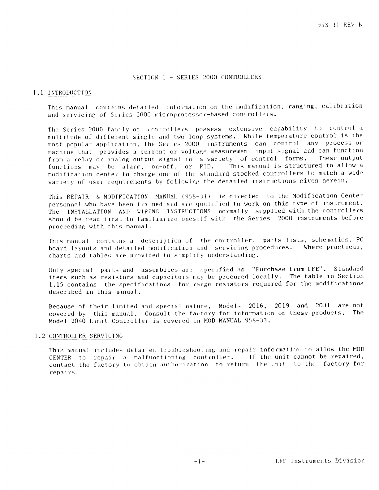
Thrs
manual
conta.iris detat Led irrfornrat.ion
crrr
the tnodrf
icatron,
ratrging,
calibratron
and servictng
tll
Ser
ies 200t1
rr icroprocessclr-based
control lers.
The Series
2000 fanri ly
oi
oorrt rollers
possess exterrsrve
capability
to
cttntrol
;r
multitude
of
dtffer-errt sinsle
ancl
two
loop
systerrs.
While
temperatul-e
control
is
the
fltost
popular
appljcatiorr,
t.hr: Ser-ies 2000
]nstrumetlts
can
colltrol
any
process
or
machrle
that
provides
a cur
rent ot voltage
rneastlrelTient.
rnput
srgnal
and
can
f unctrotr
fron a
reliry
or analog out.put
sjgnal l-n
a variety
of control
forms.
These
output
fun<rt,rons may
be
alarnr
,
orr-of f , or PID.
This
manual
is
structured
to
allow
a
nrgdi.flcilIton
center to change
rrne of
t.he
standard
stocked
cotrtrollers
to nr;rtch
a
wide
var-iety
of user requirernents
by fol lowing
the detailed
instructlons
glven
herertt.
Tirrs REPAIR
& MODIF'ICATION
MANtlAl,
(958-11
) is
directed
to
the Modrfrcatiorr
Center
pelsotllel
who have beel
tratned arrd
are
qualif.red
to work
on
this
type
of
inst.rtllrrent.
The INSTALLATIoN
ANI)
ItIIRING INS'IRU0l'ItJNS
normallv
supplred
with
the
controllers
should be
read first t.o fanriliarrze
oneself
wittr
the Series
2000
instrunrents
beftlre
proceedrng
with
thrs marrual.
This nranrra.l
contails 4
descripLir-rn
of
tlre corttrttller',
parts
lrsts,
schernatics,
PC
board layorrts
a1d flel.ailed
nroclif ir:atiorr
:rnd servicirrg
procrtdtlres. Where
practlcal,
charts and tables
are
providerd
ttt srrnplrfy
understatrdjng.
0nly specral
part-s
arrd
assernblies
are
specrf i.ed
as
"Purchase
f rom
[,F8".
Standard
ltems such as
resistors arrd
capacitors
may be
procured
locally.
The
table
i.n
Set:tlcrn
1.15 contains
the specificatlons
for- range
resistors
required
for
the modifications
described rrr
this nrarrual.
Because
of thei r I rnrr ted arrd
spec ial rratrrr
e,
Models
2016,
2Ol9
and
2031
are not
coverecl by
this nranual.
Consult the
f actory f
ori nf orntat-rorr
on
these
products.
The
Model 2040
Lrmit Controller
is covered lu
MOD MANUAI,
958-33.
I
.2
cONrRor,L,E&
llBVIll
Nq
'Ihis
nrartrrai rrrr:lrrdes
detailerl trorrlileshoutirrg
arrd
repair
rnforrnatlotr
to allow
the MOD
CFINTER
to repair
a rnalfunctioning
controller.
If
the unit
cannot
be
r-epaired,
contact.
the fac:
tory t() oblarn authorjzat.ion
to returrt
the
unit
to
the factory
for
repal
rs,
-l-
LFE
Instruments
Divisiorr
'j55-ll
RL.\r
B
Fo
I lowrrrg
p
rope
r
brief
descriptrotr
1.3
authorization,
the
contr-oller
should
of
the
observed
problenr
and
shrpped
pr
LFE
Instruments
Dtvision
Repair
Departnent
11655
Chrillicothe
Roarl
Chesterland,
Ohlo
44026-1994
(216)
729-1681
t0
be
adequately packed
\rrttt
a
epaid
to:
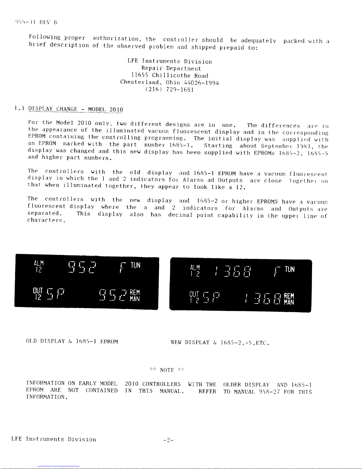
For
the
Model
2010
only,
two
dlfferent
desigrrs
are
in use.
The
drfferences
aie
'r
the
appearance
of
the
-il
luminated
vacurrnr
f
luorescent
display
and
rn the
col.resporrrl
rng
EPROM
cotrtaitrinB
the
controlline
programming.
The
j.nltial
display
\,ras
strpplred
wrth
an
EPROM
marked
wlth
the
part
number
l685-1.
,startrng
about
Septembei-l98l,
the
dlsplay
was
changed
and
this
new
drsplay
has
been
supplied
wlth
EpRoMs
l6g5-2,
l5g5-5
and
higher
part
numbers.
I'he
colltrollers
with
the
old
drsplay
and
1685-l
EpRoM
have
a
vacuum
fluorescent
di'splay
rn
which
the
I
and
2 indicators
for
Alarms
ad
outputs
are
close
togethei
so
that
when
illurnrrrated
together,
they
appear
to
look
like
a
12.
a$&al_qa!q!_
MODEL
20
The
cont
ro
1 lers
with
the
new
fluorescent
drsplay
where
the
separated.
Thls
display
also
characters.
display
arid
1685-2
or
hlgher
EPROM,S
have
;r
vacuum
a
and
2
tndrcators
for
Alarns
and
Outptrts
art:
has
decimal polnt
capability
in
the
upper
line
of
0L,D
DISPLAY
&
1{r85-l
}iPROM
INFORMATION
ON
EARLY
MODEL
EPROM
ARE
NOT
CONTAINED
I NF'ORMATION.
NEW DISPLAY
&
I 685-2
,
-5
,
ETC
;!;':
Na)T
F
/:
:':
20
IO CONTROLLERS
WITH
THE
OI,DER
DISPI,AY
AND 1685-
1
IN
THIS
MANUAL.
REFER
TO
MANUAL 958-27
FOR
'IHIS
LFE Instnunerrts
Divlsion
_')_
1.4
r::l-
CAUTI0N
TO
I)REVENT
CONTACT
DETERIORATION
DUE
TO
DISSIMILAR
METALS
'
DO
NOT
I
N'II]RM
I X
I
I
O
BOARD
AND
CPU
BOARD
GOI-D
AND
SOLDER
PLATED
TERMI
NALS
'
AL,S(I
MAKE
SURE
THAT
THE
EDGE
CARD
AND
CASE
TERMINAT'S
ALSO
HAVE
THE
SAME
TYPE,oFPI,AI,ING.FAILURE,TOFOLLOWTHISINSTRUCTI0NMAYCALISE
CON'TRO[,T,ER
MAI,FUNI]T
ION .
r
.5
qo_!!TBll!,LE&
IDENI
rFI!rATI-qN
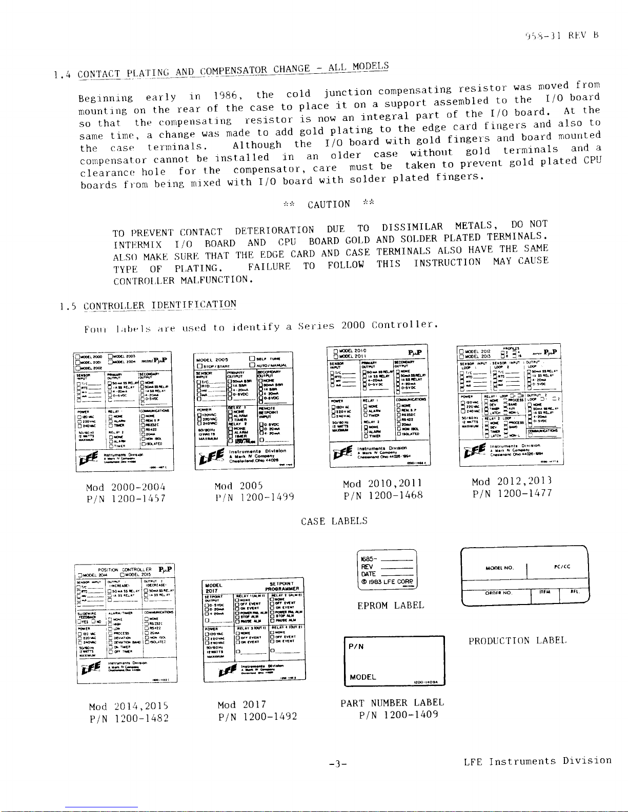
F0tti
l;rtre
ls
;rre
ttsed
to .tclerrtif
y
a
Serres
2000
Control
ler'
l.rt.uh.nlr
orvrlon
Cr.rdd
tu..6-B
'iiB-11
Rflv
B
co!!t4!I
-LILA
r
I
ltq-
4N-D-qoI',tPEt{-'14roR
CHANGE
--4!!-!Lo!J!',s
Beginni'g
early
ln
198b,
the
cold
junction
compensating
resistor
was
moved
from
rTrount
jng
on
the
rear
of
the
case
to
place
it
on
^-t'-tppott
assembled
to
the
I
/o
board
so
that
the
c:o*persatirrg
resf
stor
i,
no"
un
,-ni"r.ut
pu.a
of
the
I
/0
board
'
At
the
sarne
timrr,
a
change
was
made
to
add
gold
platrng
to
the
edge
card
finters
and
also
to
the
case
ternrrnals.
Although
the
I/O
board
w'ith
gold fingers
and
board
mounted
conpensator
cannot
be
installed
in
an
older
cas(l
without
gold terminals
and
a
clearancr:
hole
for
the
compensator,
care
must
be
taken
to
prevent
gold
plated
CPU
boards
f
r-orn
betne
n,jxed
with
I
/o
board
with
solder
plated
f ingers
'
Mod
2000-2004
P/N
1 2OO-14\7
Mod
2014,2015
P/N
1200-1482
XOEL
SEIBiT
PNOOiATXER
oo-aw
o
---,,__
od.
efr
oq
l[it
ox's
0da
Od'
.vtir
t_
I
oMau
o-
,tF'W^--.
F,PROM
LABEL
P/N
MODEL
PART
NUMBER
LABEL
P/N
1
200-1409
Mod
2005
Mod
20 10,20
I
1
l,/N
1200-1499
P/N
1200-1468
CASE
LABEI,S
Mod
2012,2011
P/N
1 200-1477
Mm:t
No.
I
rcrcc
ornrr
No
tft
PRODUCTI(IN
LABET,
Mod
2017
P/N
1200-1.492
Ore&
o2Fv&
O
r.o*
o
1.__
3tv
_
ad_
od
D1€
Bri,#
H:::-
l^drumn[
Drvr16
cbdtu!6_@
EffiEi:sl3
rj:lr
_:_1.
r=
tEI=
iE,#""
ld
3ffi
l%
l:f
E..B:o
:g:*
Posrre csmftr
ER
Pu?
3m
ry
OreE!
rcr!
e@.d lffi l@6,
l,,ictE' lrddtst'
i
ni]-
I o
s-
s r'- j o
-.s'r--
e--1-r,.'r.LN lD'r$eN
l
-3-
LFE
Instruments
Di.vi-sion

:,r'i-Jl
RL,\'lJ
The
CASFI
L,ABEL
rs
located
on
the
outsrde
top of the
Serres
2000 case.
l'h r s labe I
h.rs
space
foi^
rdentlfying,
the
prrmary
and
secondary output,
alarm,
setlsor
and supply
volt'age
specif
icatrons.
Any
lnput
or output
hardware
rnocllf
lcation
to these
controllers
requires
that this
label
be remarked
or replaced
with
a new
label and thr:
appropriate
conf
rguration
nrarked.
The
coutroller
PART NUMBER
LABEL
is
located on the
mother
board at the
rear
of the'
front
beze-l
assembly.
Any
modificatron
to
a
Serles
2000 controller
requlrt's
that
this
label
be
changed
to
irrdicate
the
part
number
shipped.
The SpAN
rs
also lrsted
on thrs
label
and
must be
changed
when
the span linrits
ar-e changed.
Ihe
EPROM
LABEI,
is attached
to
the
EpR0M
at
EPR0M
part
number,
its
revisjon
letter
arrd
changed
ln any
way.
Reprogramming
the
replacetnent
EPROM
ts required,the
new EpR0M
'l'he
PRODUCTI0N
t,ABEL
is
located
next
to the
fr-ont
flange.
This
It
rdentifres
data
relevarrt
to
modrftcatfon
h;rs been
completed
the
tinre of
nanuf actuye arrd
specif
jes
t
he
date. This
label
rs
NOT
to be rerrroved crr'
EPR0M rs
a factory
procedure.
If a
will
have its
own label.
on
the
out.stde
top
of the
Serres 2000 c()rttl'oller case
rs
the
production
control
label used
by the factor)i.
the
manufacturing
cycle
and may be covered
up after a
since the data will
no
longer be needed.
LF E Inst ruments Divis
ron
i5B-ll
RF\I
IJ
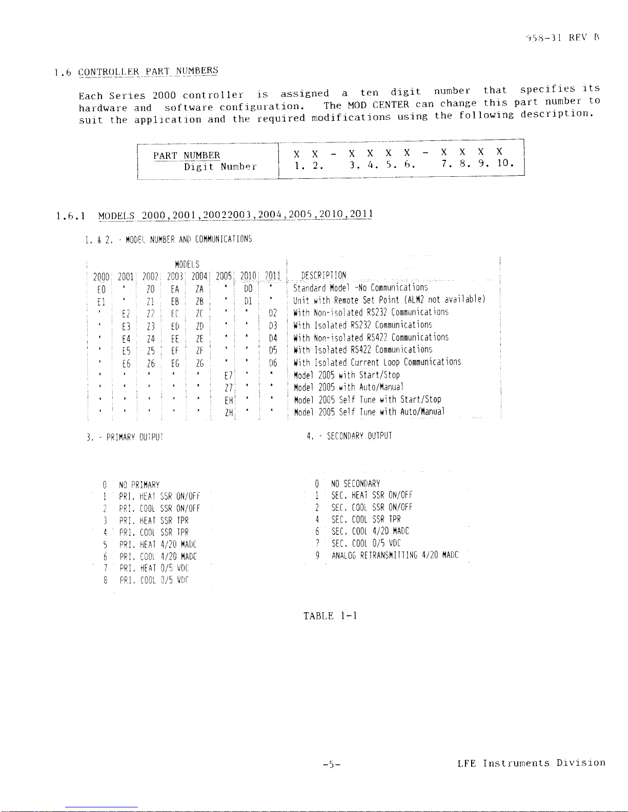
r.6
qqryM,L_LqB
g4Br
Nqf{9qR!
Each
Serres
2000
controller
is
assigned
a
ten
dicit
number
that
specifles
lts
harclware
and software
confl€luration.
The
MOD
CENTER
can
chanBe
this
part
number
to
sutt
the
applrcation
ancl
the
required
modificatjons
using
the
following
description'
l
. 6 .
r
YO!4!,!
2000
,
2o0
)
,2o_9?299)
,299!.2.0!5
-ZQ
1-0_120
!-!
1. & 2,
fl0DEl-
NUI'IBIR ANtt
t0l'11'1U|.l
ICAT l0NS
i
fl0Dtls
'
lnnl
r'tn1
lnn?
)nnI
?nnA' ?nn5 701il
'
zL'uu
zvul
1"u.' 4uv / aut'1.
,
t0,
10 EA,
lA1
',
D0
11
'
:r
FR
IB
,
'
DI
LI
LI LU
'
t;
1
il 1t
I
I'.ri,zl
,
it,'lDi
'i
,'
rq u
[[,
lt
', t
i
'
t5 l\',
rt
ff',
'i 'l
.
i6'
16,
tG
lG,
'.
'|
.
.
':
I
I
'
I
'
I I
'
.
F|lI
r:
3, _ PRII'1ARY
OU]PUT
[l
|.]O PR II'IARY
1
PRI,
|']TAI
35R O|IIOFI
?
PRi. COOI SSR ON/(]FF
]
PR],
HIAI
SSR
TPR
4
pRt
, c00t ssR
IPR
5 PRI.
i]EAT 4/20
ilA|)[
6
Ppt.
l00r
4/20 l'lAD[
7 PRI, ilEAI O/5
Vt)I
8 PR I , f 00r
0/5
l/0l'
I
2U1
i,,
DtStRIPlloN
';
'
l"StJndard
lodel
-No
Communicatlon:
'
Unit
rlith
Remote Set
Point
(ALl'12
not
available)
D2
flith
llon-isolated
RS232
Communications
t)3
, t{ith Isolated
RS232
Commttnication.c
D4
t4ith
|'ion-isolated
RS422 Communications
D5
I |littr Isolated
RS422
Communications
D6 r llith
lsolated
Current
Loop
Communications
-
,
l'lodel
2005 lrith
Start/Stop
'
i
l'lodel 2005
* ith Auto/l'lanual
^
I
l'lodel 2005
Self
.Iune
with
Start/Stop
,
,
flodel
2005 Self
Tune
with Auto/l,lanual
4.
.
SECONDARY
OUIPUI
O
NO SECO|IT)ARY
1 SEI,
HTA.t SSR
()N/OTT
2 Srf,
t00t ssR
0N/0FF
4 STC,
CO{]L SSR
IPR
6
StC, C00t
4/20
|,IADC
7 SFC,
COOI O/5
VDC
9 ANATOG
R[]RANSI'JIITIN6
4/20
I'IADC
TABI,E
1 - 1
r4ts!-t*!EB
-----]-;;
-
;;
x
x-=-I
I r,"
-l
Drgit
Nurnber
I
l.
2.
3.
4.5.6.
7'
8'
9'
10'
I
l---l
-5-
LFE
Instruments
Drvtslon

'J)5-l
I RFIV tJ
I
.6
.
1
UqllFL.>?q_0q_2q0!,?0q?,
2003
,
200trr290_5_,,2!
1q,?01 t_( contr_nued
)
5.
&
6,
.
I|!PUI
CO[)T
00
J
.IHIRI'10t0UPtt
O1 |( ]|lERI'IOCO(JPLE
O2 R IHTRI'IOCOUPLI
t]]
S THERI1OCOUPLE
04 T THIRI'IOCOI']PIT
05 N
T|.1ERI{OCOUPIE
06 t THtRI'10c0tJPti
O7 B
THERI'lOCOUPLE
OB
PI AT]NIL
I I
IHERI'lOCOUPLT
09 Ni/N11Bt'lo
I|1tRI'10C0UPLt
10 li5?Re/l{26?Re
Tl-]ERT'{0C0UPLE
], ' PRiI,IARY
OTIIPU'I
,
(t00P
ilL
lNtY)
|
0
N0
[ rTDl't_
L
r-tA'
;!F
,t,:,,]c
I
I i 00 .51
0\/0FF
I ltA-:5RltP
:
4
0':,qa'pR
5
-fATd,'20l]1A0[
,
5 I t00t 4/20
mA0t l
'
r'a'0/5
vDt
8 [0tL 0t5
u0t
'
a
il'[^/
qF_Ay
I
et'Rail:lilrov
,
t
Ri.|RA'lst'{lT
SP
7, OR 8, - ALAR]'1 CODI
O NO ATARII
1
HIGH
PROCTSS
2 t0l'l PR0CtSS
3
HI6H DTVIA.IION
'
l.lot avai I
abl e on
l'lodels 2002,
2004
or 2005
(27
or Z|]),
4 t0l1
DIVIATI0N
f
t'lodel
2005 only,
5 0N IItltR
'
6
OFF TII(ER'
7
I)TVIAIIO|l
BAND
9 REiIOIT PAUSE
#
Ll
fil?Pe/i,125?Re
THtRlilOC0UPtE
7,
&
10, - SPICIAt C0Dt
12
lllli2b?Re
I||ERI'10C0UPtt
20
lOOA
Pt
FID
i" RISOTUIION
?1
1OOA Pt RID
0,1"
RTSOLUIION
40
0/5
VDC
60
,1,,lf
mA0t
b1
4i
?0 mA|ll
:t
r
P014tRtt)
r.6.2
ryq!_E-t,s
2_q!?_&
zqll
1 , &
2,
-
r'100tt
&
PR0t
lLt
StLiC.t I0|'l
OO
.
STANDARD UNII
Att OI|lIRS
-
ASSIG|{ED BY FACTORY
N0it: tARtY
C0NIR0LLtRS l'1AY |,{0.I
|iAVt
I|"iIRI'lOCOUPLE ]YPtS
05, 09, 10,
11 0R 12,
TABLE
I-1
(CONTINUED)
4,
_
SFTONDARY OUTPUI
(r00P
fl1
0|'rrY)
O NO O|]IPUT
i]TAI
SSR
ON/OTF
COOL
SSR ON/OFF
'
.4 fnn
(eD
TDo
l'10D
t L S
?f12 ;
2013
TDESCRIPil0N
1/0 C0rl'1,
lrl-n
(0lrih,
l4/0
t0i!i,1, filTH
tOr'tl'l
81
85
,'C1
''fa"
2PROFILES
82
i
86
,
C2
I
C6
i
4PR0FIL[S
3T 87
t]
'
C7
I
BDBOFIIIS
84 88
,
t4 .
lB
.
16 PR0FI[[S
6 r C00l
4/20
mADC
B,
l00t
0/5 VDC
I A
] [VENI RITAY
. B RTTRA|'iSI1II
PV
l].RETRA|'{SI'1II
SP
TABLE I-2
-6-
LFE
Instrurnents
Divrsion
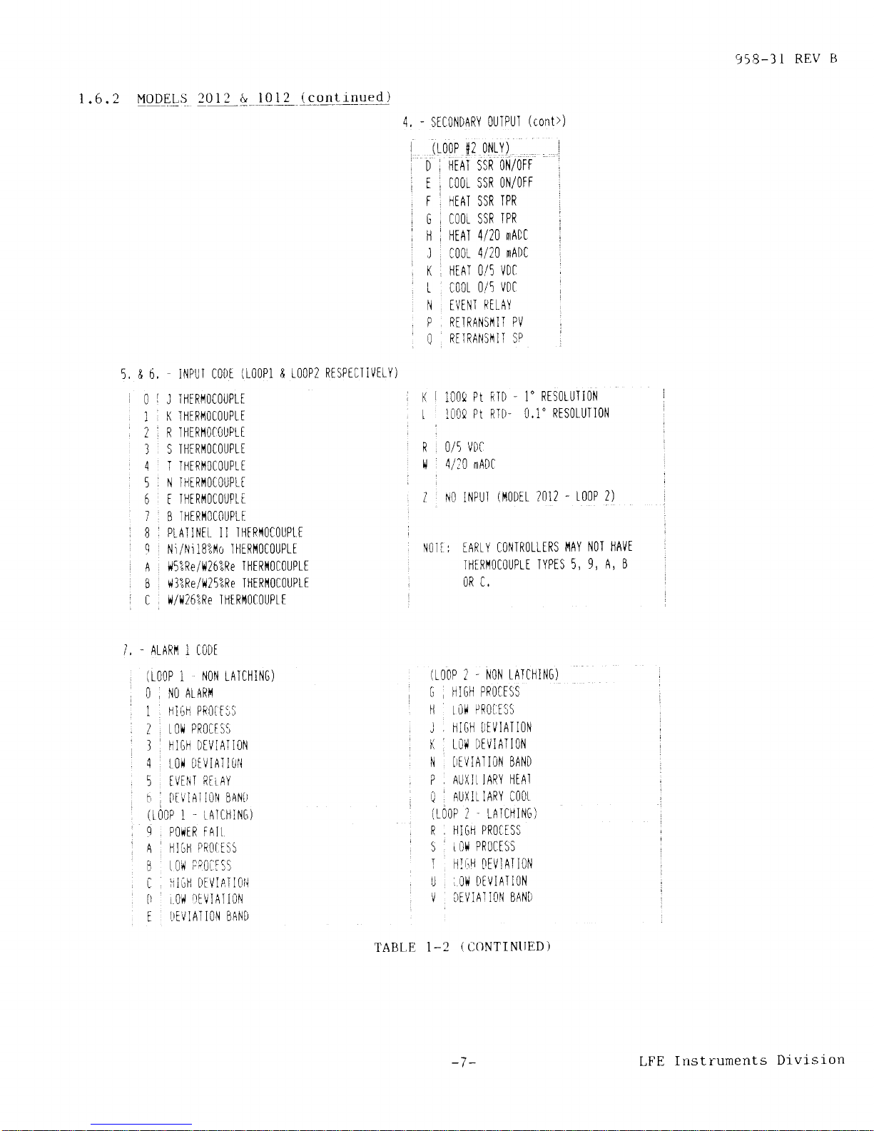
1
.6.2
Uqlqlsj
?q12 !
Ql2_
(
continued )
StC0l'lDARY
0UIPUI
(cont>)
1!-00P
{2
0l'lLY)
I
D
I
HrnI SSR
otl/OrF
t
i
C00t SSR
0N/0FF
F i IIAT SSR
TPR
G
i
C00t SSR
TPR
|.|
i
l.|[AT 4/20
mADC
I C00t
4/20
mADC
K , HIAT O/5
VDC
t . COOL
O/5
VDC
N IVINI
RITAY
P.
RI]RANSIII.| PV
0
RtiRANSI'IlT SP
|( I lOOA
Pt
RTD _ 1"
RTSOLUIION
I
lUOA
Pt R.|D.
0.1"
RESOTUTIO|l
R . 0/5
VDC
ll
,
4/10 mADC
I
N0 TNPUI
il'l0Dil
?012
-
t00P
2)
N0Tf: IARtY
C0|iIR0LLtRS
l'lAY
N0I |]AVt
THtRI'l0cOtjPtt
lYPts 5,9,
A, B
OR C.
958-31
REV
tJ
4,
I
:
I
5, & 6,
L
RTSPTCI IVTTY)
0l
1,
2t,
I
4'
5i
6
l',
Bi
qi
:
Al
B
C
iNPUI
C00r
(100P1
& t00P2
J
I|]ERI'lOCOUPLI
K THIRI'IOiOUPLi
R
T|lERIIOTtlUPtI
S THTRI'IOCOUPtE
I I|lERIIOCOUPtE
N
I|1iRI'IOCOUPtI
T
IHIRI'tOCOUPLT
B
IilIRI'lOC{)UPLT
PTATINTI
I I
IlTRilOTOIJPI"T
N r
/N
i
18?l'10
TlltRl'10C0UPtt
fl5ZRelll26?Re
I|lERIiI0C0UPLE
$ l?Re/i425?Re
I|1ERI'l0C0UPtE
ll I t26ZRe I Hi Rfl0C0UPt
E
ALARI'1 I itlDI
(tOOP
i
|.{ON
tATCHIN6)
O N(]
At ARI'1
1
|lI6i1 PR0tt5:j
2
[ 0ll
PR0C[55
]
HI6H DtVIAIiO|l
4,10i]
DtvlAllirt{
5 tVtf!T
RtiAY
h , OT!IAI]U|i
BAN|)
(tOOP
1'LAlCHI|'1G)
9
POiItR
FAII
A
fll6il PR0t_ts5
I | 0i4
pp0i-rss
C
fil,H
t)FVIAIl0ll
0 i 0l{
ltvIATi0l'1
I
I.)IVIA]IO|'1 BAND
(tOOP2-|1(]|.itATC|"]lNG)
G FrIGl.l PROCFSS
H
I OIi
PROI,ESS
J
i,]IGI] |)iVIATION
|( . tOiI
DIV]AIION
l'l I)iVIATIO|'1
BAt.lO
P
AUX]IIARY
HIAI
Q
.
AUXILIARY
COOI
(t0OP
2 TATCHING)
R
|"]IGH
PROT
ISS
S ,
Li]Ii
PR(]CISS
'f
ilI
.,H 0tvlAI
iliN
U
IOII DIViAIION
V OIVIATlC|{ BAND
TABI
E 1-2
(
CONTINIIED )
-7-
LFE Instruments
Divisron
J>r-Jl
REV
B
I
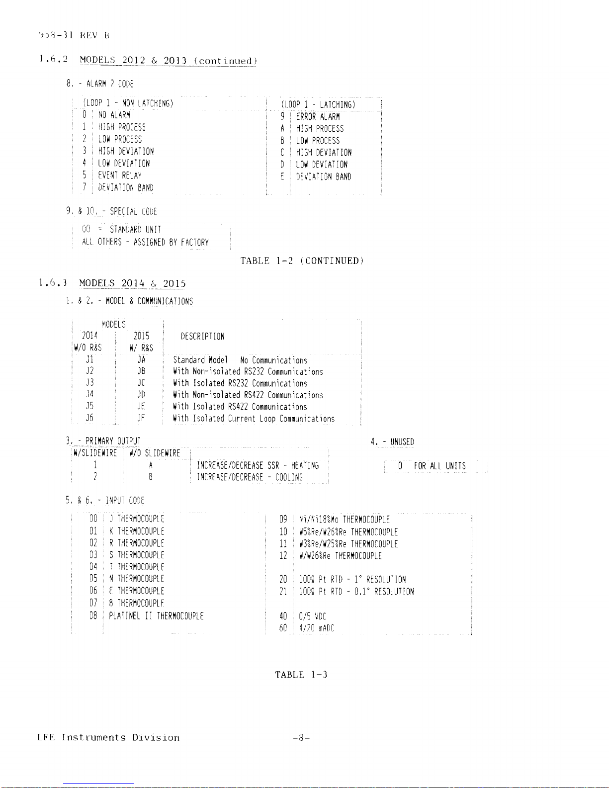
.6.2
MODELS
2012
&
201i
(
cont
irruerl )
B..ALARl'I2IO|)E
(LOOP
1.
NON
tATCHI|]G)
i
0i|l0ALARtl
I
1 r |-|IGHPROCTSS
'2.10*PROCISS
;3IHIGHDiVIA.IION
4
:
t0l{ DiVIAII0N
I
5:tvtNTRttAY
i
TiDiVIATI0|.lBAND
I
(t00P
P1.IA]CHI|.IC)
!
ERROR
ALARil
I
ln
iB
ic
t0
:I
HIG|| PR0CISS
I
t0i4
PR0ctss
.
HIG|I
DEVIATION
J
Lo|l
DEVIATI0N
I
DtVIAll0l'] SAND
r
9, &
10,
-
SPFIIAL
r-0LlF
L:'r
'
STANlrARl
Ullp
:
Art
0riltRs
-
ASstGNID
BY FA(]IoRY
i
TABLE
1-2
(CONTINUED)
1.{r.
J
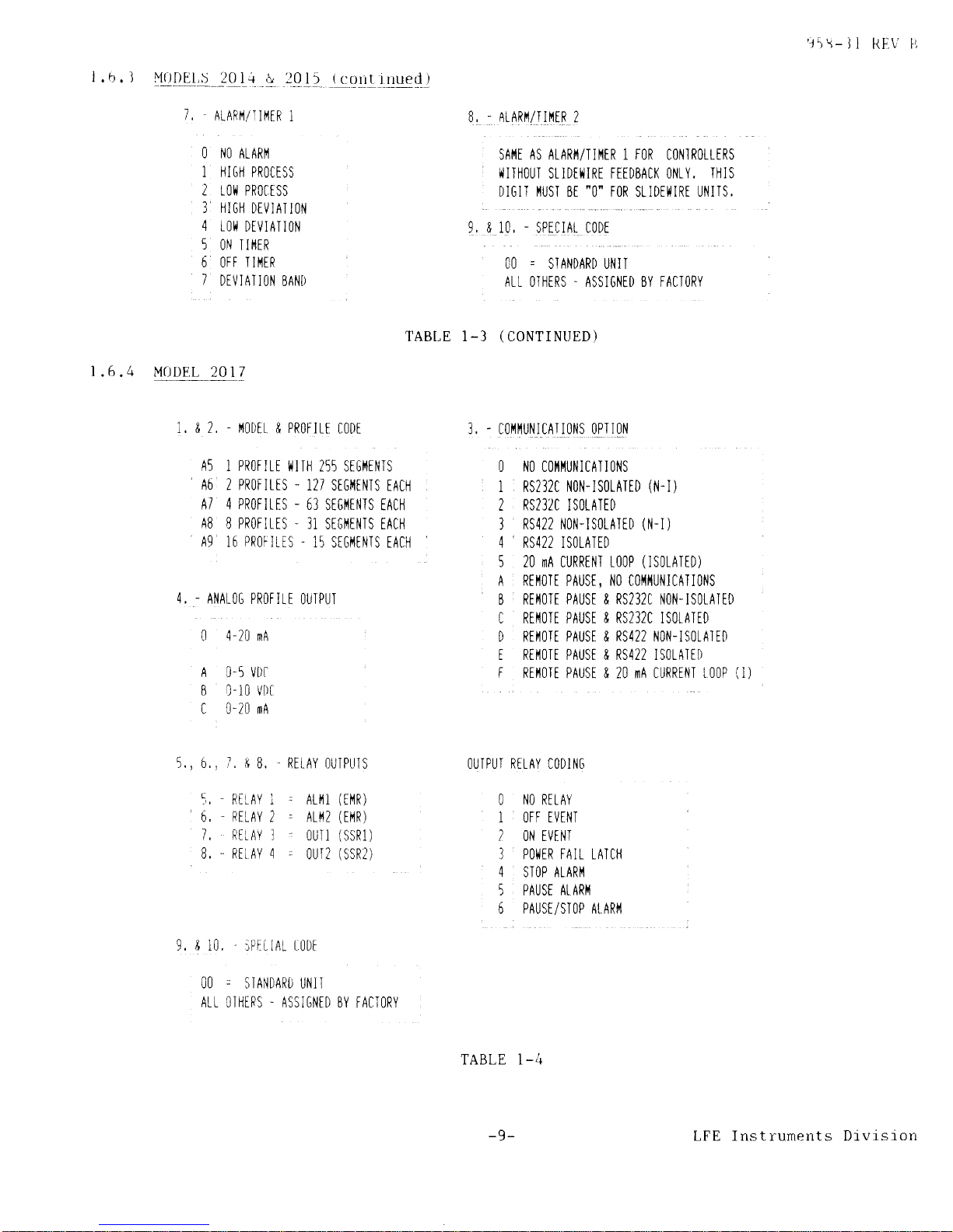
{qqE_L_.s
2_oJL
-&_
!0L5
1,
& 2, - t'l0t)tL
& C0t'll'lUNICATIO|\lS
,
h0DELS
i
,
',
2014
i
2015 I DESCRIPTION
i
tuO
R&s
ii/
R&5
,
,
11
JA
Standard
flodel |{o
Communicat ions
,
:
J?
.
JB : l,lith
Non-rsolated
RS232 Communications
.
Jl
Jt
'
ilith
Isolated
RS232
Communications
J4
JD ' l{ith Non-isolated
RS422 [ommunicationr
J5
,
lt ilith
Isolated
RS422
Communications
:
J6
,
lF
'
ilith
I;olated Current
Loop [ommunicat
ions
3,
'
PRII'IARY
0UTPUI
4, - UNUSED
itsL
rorwrBr
frlo
sr rDriltRr
]
A
INCRTASI/DICRTASE
sSR. |lIA'IN['
O
FOR
AtL UNITS
',
7
i
s
ir|1cRrRsilorcRtAsE-l]00li|'lG
:
5. & 6,
-
I|lPTT CODE
00 .t
-rlERf40f0uPr[
09
\i/Ni18""lrlo
THtRI'l0rOLJpL[
r
01 i K
.IHERf'l0C0UpLi
l0 li5""Re/lrl26?Re
.I|1[RI'10[0UPLE
i
02 i R IHtRil0C0UPtt
!
11
,
li3";Re/1i25?Re I||tRt'1gCgUPtt
03
iSIHFRI'10C0UPI[
i
12t l4l1,125?ReT|1[R||0C0UPIE
,
04, T TfttRt'l0C0UPLt
,
i
05 , |i
I|ltRt'l0C0UpL[
,
20
100a
pt
RTD - 1" R[S0LUTI0|.i
.
06 i F IHERtl0C0UPtt
?1 1000 Pt
RID - 0,1" R[S0LU.II0N
i
0i i B
Il"1tRt'10COUPt
F
i
08 i PLAI]NEL
II
T|IIRI'IOCOUPLT
!
40 i O/5 lDC
,
,
60
. 4/20
mADC
TABLE I-3
LFE Instrunents
Drvrslon
-8-
'15\-11
RIi.t/
l'l
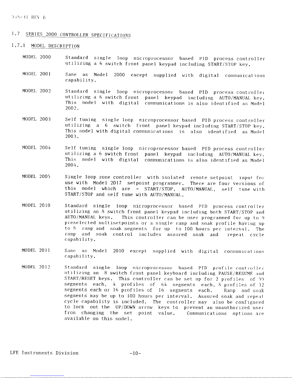
l.b.I
M0DEI,S__201.{
& :015
(coltrrrued)
1 ,
AtARr'l/
til(iR
1
O NO
ALARI'1
1 HIG|l PROCTSS
2 r0it
PR0ctss
3 |lI6|i
DIVIA]
ION
4
tOIi
DTVIATION
5
0N T If'tER
6 0FF TII'ltR
1
DTV ] AT
i ON BANI)
B,
ALASr'1lrlili8
2
sAr'rt AS eLiniZrrr,trn
r
toB
colrnoiLrns
I{ITHOU'I
SLIDII]IRI FTIDBACK ONtY.
IHIS
DIGII iIUST
BE
"O'FOR
SLIDEIIIRT UNITS,
9, & 10, - SPECIAt C0DE
OO = S]
ANDARD
UN i I
Att OIHTRS.
ASSIGNID
BY FACTORY
TABI,E 1-3
(CONTINUED)
|
.6.4 MODEL
20 1
7
1, & 2,'r(0DtL & PR0r-trt
c0Dt
3, - cOl'lt'ltJt'llcAII0NS 0iTloll
A5 I PROFItT
iIIT|] 255 SIGI1TNIS
O |'lO COI'II'IUNICA.I]Ot'{S
A6 2 PROFILIS
-
127
SIGiIII'ITS
IAC|I
1 RS232C NO|'I-]SOIAIID
(|.l-I)
A7 4
PROFITIS
-
63
SIGI{I|'ITS TAC||
2
RS232C
ISOLATID
AB
8 PROFITIS . 31
SIGI'ITI,IIS TACI1
3
RS422 NON'ISOLATiD
(N-I)
A9
16
PROF]LIS
.
15 SI6I'1E|'iTS IACil 4
RS422 ISOTA]TD
5
20 mA CURREl.lI
t00P
(lS0LATtD)
A R[t'l0II PAUSE, NO COI'II|IUiIICATIONS
4,
-
ANATOG PROFITI
OUIPUI
8 REI'IOTE
PAUSE & RS232C
I'IOi.{-ISOLAITD
0 4-20 mA
I [il3[ lli:: I
[3i]l'-li!ii;il,''
I RII'1OIt PAUST & RS422 ISOTATID
A
0-5 VDi
F
Ril't0lt PAUSE & 20 mA CURRIN]
t00P
(l)
B l-10
t'Dt
C 0-20 mA
5., 6,, I. &
B. REI AY I)UIPI]TS
5,-RrLAYi. AUil(iflR)
6,
'RELAY
2 . ALf'12
(Et'1R)
7.
RitAY
]
.
OUII
(SSR1)
B,-RIIAY4
-
OUI2(SSR2)
OUIPUI RELAY CODII'I6
O
|'lO
RELAY
1 OFF EVTN]
2 O|l TVINI
] POIIER FAIt LA]C||
4 STOP ALARI'I
5 PAUSE AtARI'l
6 PAUSTISTOP AtARil
9, & 10, iP[L r At r0Dt
OO . STANDARD
UN]T
Att O]HIRS.
ASSI6|{iD BY FACTORY
TABLE 1-4
-9-
LFE Instruments Drvision
lr\-Jl
Rhl
tJ
I
.7
sER!E!_?.0!QIqNTR0LLER
spECrFrcATroN.s
1.7.
I
MODEL
DESCRIPTI(]N
MODEL,
2OOO
MODEL
2OO1
MODEL
20O2
MODEL
2OO3
MODEL
2OO4
MODEL,
2OO5
MODEL
201O
MODEI-
201
1
MODEL
20 I 2
Standard
single
loop
microprocessor
based
PID
process
controller
ut1l1zing
a 6
switch
front
panel
keypad including
srART/srtjp
key.
Same
as
Model
2000
except
supplied wrth
digital
cornmunicattons
capability.
Standard
single
loop rnicroprocessor
based
PID
process
corrtrol
ler
utrlizing
a
6 switch
front
panel
keypad
includrng
AUTO/MANUAL
key.
Thls
rnodel
with
dieital
cornmunications
is also
ident ified
as Model
2002.
Self
turring
single
loop
microprocessor
based
PID
process
control
l er
utilizing
a
6
switch front
panel
keypad
including
srARTi srop
key.
Thjs
model
with
dieital
communicatiorrs
is
also
identified
as Morl
e1
2003.
Self
tuning
single
loop nicroprocessor
based PID
process
control
ler
utilizing
a
6
switch
frorrt
panel
keypad
including
AUTO/MANUAL
key.
This
model
with
digital
comrnunications
rs
also identifled
as Model
2004.
Srngle
loop
zone
controller
with
rsolated
remote
setpoint tnput
for
use wlt"h
Model
2017 setpolnt
protrammer.
There
are four versions
of
this
model
which
are
-
srART/srOP,
AUT0/MANUAL,
self tune with
START/STOP
and
self tune
with
AUT0/MANUAL.
Standard
single
loop microprocessor
based
PID
process
control
I er
utrlizing
an
8 switch
front
panel
keypad includirrg
both START/STOP
and
AUTO/MANIIAL
keys.
Thjs
controller
can be
user
programmed
for
up to 9
preselected
multisetpoints
or a single
ramp
and soal<
profile
havirrg
up
to 8
ramp
and
soak segments
for up to
100 hours
per
interval.
The
ranp
and
soak
control
includes
assured soak
and repeat
cycle
capabilr-ty.
Same
as
Mode
I 20 l0
capability.
except
srrpplied with
digital
conrmunicat
i ons
Standard
single
loop
rnicroprocessor^
based
PID
prof
rle corrt r-o11er-
utilizing
an 8
switch front
panel
keyboard
irrcluding
PAUSE/RESUME;rrid
SrART/RESET
keys.
Thi-s controller
can
be set
up for 2
profiles
of
j')
segments
each,
4
profiles
of
64
segments
each,8
proflles
of
l2
setments
each or
l6
profiles
of 16
setfirents
each.
Ranp and
so;rk
setnents
may
be up
to
100 hours
per
interval.
Assured
soak and repeal
cycle
capability
is rncluded.
The
corrtroller
may also be
confrgured
to lock
out
the
UP/DOWN
arro\t
keys
to
prevent
an
unauthorized
user
fronr
changing
the
set
point
value.
available
on
this nrodel.
LFE
Instruments
Divis
ion
-10-
Communications
options
are

t
.7. I t-,lODLL
DFlStlRi
l1l
ltN
i!(rUIlIN!l_E_!!
MODEL
20 I 3
MODEL 20 I 4
MODEL
20I5
Jrr-J1
RI'.\'tr
to Model
2014
except that
rt
also
has
the
and soak
capabilrties
as descrrbed
for
Mrldel
dieital
communications
is
also
jdentrfled;rs
Standard 2-loop microprocessor
based
PID
profrle
corrt
r o1 ler
utiltztnt
an B switch
front
panel
keypad
lncluding
PAUSE/RESUME
;rnd
START/RESET
keys. This
controller
is identical
to Model
2012
except
that
tt
cart
control two independent
process
loops and
is
supplied
with
one
alarnl event relay.
mode
I
.
Communrcations
options
are
available
on
thrs
Standard
single loop rnicroprocessor
based PID
position control
1er
utilizing an B switch front
panel
keypad
irrcluding
START/STOP
and
AUTO/MANUAL keys.
Thrs controller
is
speclfically
designed
for
use
wlth an
external AC reversible
electric
motor
operator
havrng
a
feerltrack
potetrtionreter.
A
separate
version
of
the
Model
2014
is
avarlable
for use in applications
wlthout a
feedback
potentrometer.
The
outputs
are lA solid
state relays
to
drive
the
motor
operator.
One
alarmltimer
relay 1s
supplied.
Thjs
nodel
with diSit.al
cornnrunications is
also ident-tfred
as ModeI
2014.
Thrs model 1s identical
multisetpoint and ramp
2010 . This nrode I
wi
th
Model
2015.
MODET, 20 I 7
Set.point
proBramner
to
provtde
a
common
remote setpornt
for Model
2005
zone
cont.rollers.
This
progranner
may be
set up for
a
single
profrle
with 255 segments or llp to 16
profiIes
with I5
segments
each.
Fortr
event/alar-nt outputs aye
provided.
There
is no
lnput
to these
controllers. This model is
available
with drgjtal
commttnlcations.
-11-
LFE Ins*.ruments
Drvtslon
\-
i
I
i.:
t{i V
tl
!;lt\il81t
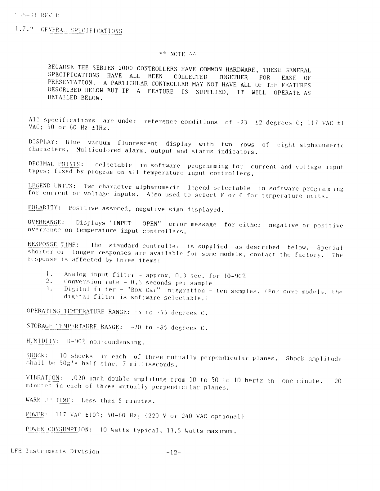
ill!.!!i
1
|AT
I ONS
IJQJ[
;,: /:
BECAUSE
THE
SERIES
2OOO
CONTROT,LERS
HAVE
COMMON
HARDWARE,
THESE
GENER]\I,
SPECIFICATIONS
HAVE
ALL
BEEN
COLLECTED
TOGETHER
FOR
EASII
OF
PRESENTATION.
A PARTICUT,AR
CONTROL,LER
MAY NOT
HAVE
ALL
OF' THE
FI1ATIIRES
DES(]RIBEI)
BEI OW
BUT
IF
A
FEATURE
IS
SUPPI,IED,
IT
WIL,I,
OPERATE
AS
DETAI
LED
BELOW.
AI
I sper:i
f rcat
jons
are
under
reference
corrditions
of
+23
t2
degrees
ll7 \'Arl
tl
!ISf'1.{!:
Bltlr:
vacuun
fluorescent
display
wrth
two
rows
of
eight
alpharrr'neri.
chalar:ters.
Multrcolored
alarm,
output
and
status
rnclrcators.
DE9JY4l
lllryls:
selectable
in
sof
tware
progranrnring
f or
currerr
t. and
vol
tagc
rrprt
types;
f ired
by
progr;rnr
on al
l temperature
inprrt
corrtr-ol
Iers.
I'-4!;EryQ
lJNIr':;:
Twrt
character
alphanumeric
legend
selectable
jn
sot
tware pi-ograrrfr
rrg,
fot
t'ttl'tent
oi-voltage
inputs.
Also
used
to
select
F or
c
for
temper-ature
rlnlts.
P(ll
4RITY:
I,ositive
assumecl
,
negatrve
slgrr
displayed.
qYU\
!'{!iE:
Displays
"INplJT
OPEN"
err-or
message
for
erther
netarlve
oi-posrrrvp
over^rilnije
on
Ienperature
]"npul,
control
lers.
B-q:jlqrysf,
l'!ME:
'Il're
standarcl
controller
is
supplied
as
ciescrrbed
below.
Specrzr1
sh0r'ter
ol
lorrg,er
responses
are
avaj
lable
for
sonre
nrodels,
contact
the
factoi-y.
Ttre
I
esportse
is
irf
f
r:cted
by
t.hree
itenrs:
I,
Arralog,
inprrt
filtt_.r
-
approx.
0.1sec.
for
2.
(loltvers'ion
rate
-
0.6
seconds per
sample
l.
Drgrt;rl
frlter
-
"Box
Car"
jntegrat.i
on
_
t
drg,ltal
f rlter
js
sof
tw;rre
selectable.
)
to-90i(
err
samp
i es
9rllt14lI."rtj
IL.-YIEE
ryEE
RANGII
:
r
5
,!!!84!E
T!{fl!8,!ALrRI.
RAN0E:
-20
trt
.55
rleEirets
C,
lo
'65
degrees
t..
(For
sorrtr.t
nroclr'ls,
lhe
Shock
amp
1i
t ucle
one
rrri
rlut e
. 20
L1!]MilllfY
:
0-907
r-ion-condensing.
SHll!,t!:
I0
shoclts
rn
r:ach
of
t hree
nrutrril
I
1y
perperrclicu
lar
p
larres
s;hall
ire
509's
hillf
sine,
7
rrr.i
lliseconris.
Ui84I!tliN:
.020
inch
double
amplrtude
fronr
l0
to 50
to
l0
hertz
rn
nrinrrt r'::
irr
r:ach
of
three
mrrtu;rlly
perpendrcular
planes.
ry48ryr-L-ltl
l]ll
P0ttER:
ll7
than
5 rninutes.
;
50-60
Hz;
(220
V
l0
l,riat
ts t
ypical;
I
240
VAC
optrorra
1)
5
Watts
rnaxrrnunr
.
:I
VA(,
ESS
r 102
oi
l.
Flq![g
_(i{),NSt
]MPT
rON
:
LFFI
Irrstrrurients
I)rvts
ion
-t2-
'153-i
l REV B
16
-
1t6
screw
FIOUSING:
Plug-rn
moldecl
ABS
to
termlnals
on
rear
barrler.
NoIS!_sErEQrflN:
f
1t ),l4
DrN
Connections
through
[]omnron
Mode:
140
dB typicar
-
120
dB
minirnum
G
60
Hz.
Normal
Mode:
65
dB
typical
-
60
dB mi-nimurn
G
6O
Hz.
TIUIIEATUB!_STABIL,ITY:
!2
uV/'C
typicat
-
!6
vv
loC
rnaximum.
I NPI]TS
CURRENL
0R
_LOLTAGE
INpltTS:
May
be
supplred
with
0/100
nrADC.
vottaee
lnilas
may
be from
0/10
mV to
0/
Maxrrnum
error
rs t2
counts.
Maximum
display
span
is
typrcal,
115
PPM/oC
rnaximunr
.
BE{,04rulQ!:
AID converter
-
MEMORY
PR0TECTION:
RAM with
I
part
in 32,000.
Lrthium
battery
backup.
RTD ranges
-
40
PPM/
"C
current,
rrrput.s
fiom 0/100
uA
to
3OO
VDC.
-3200
to
+3200
counts.
AIarnr
exceed
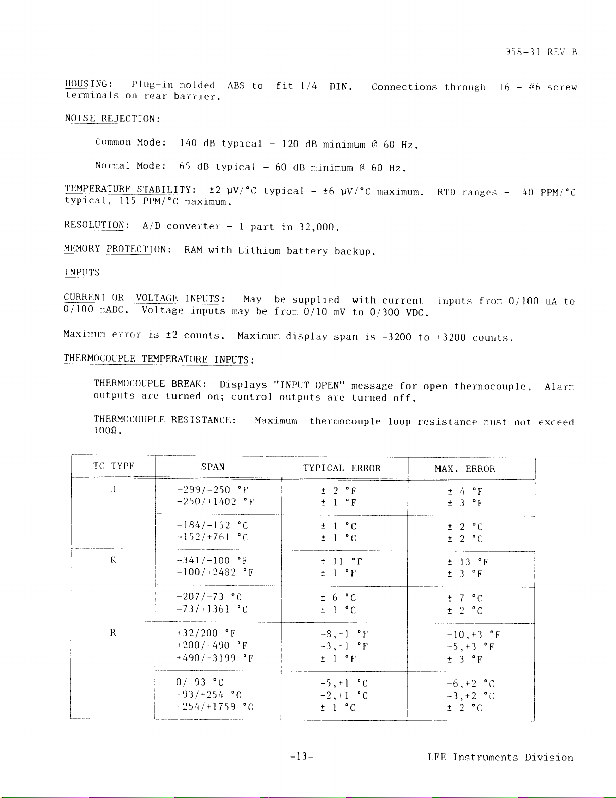
THERMOCOUPLE
TEMPERATURE
INPUTS
:
'IHERM0COIIPLE
BREAK:
Displays
"INPUT
0PEN"
message
f or open
t,hernrocorrple,
outputs
are turned
on;
control
outputs
are
turned
off.
THERMOCOUPLE
RESISTANCE:
Maxjmum
therrnocouple
loop
reslstance
rrust
not
1000.
SPAN
TYPICAL
ERROR
MAX.
ERROR
-2991-250'F
-25O
I
+1
4O2
o
F
t84
I
-152
l52l+761
+
-341l-100
oF
-100/
+2482
"F
-207
I
-73
oC
-7)l+1361
oC
+321200'F
+2001+49O
oF
+4901+3199
"F
0l*gl
oc
+93
1
+254
'C
+2541+
1759
'C
!4
t3
!2
tl
z
2
OC
OC
OC
OC
On
OF
O^
t,
OC
+
+
OF
OF
lr
I
OC
OC
1 l3
0F
t I
oF
r
OC
!()
11
7
'c,
2
0c
-.'
-l
1
-10
(
tl
+
+
'-)
r
f
) I
OF
(
a
+
-6
-1
!2
t
z t,
+1 o a
-13-
LFE Instruments
Divrsi.on
'j'>r-Jl
RI.l\;
tt
B
PLATIN!]1,
II
N1/Nll8%Mo
+321
+
185
oF
+185,+450
oF
+45O1+3181
oF'
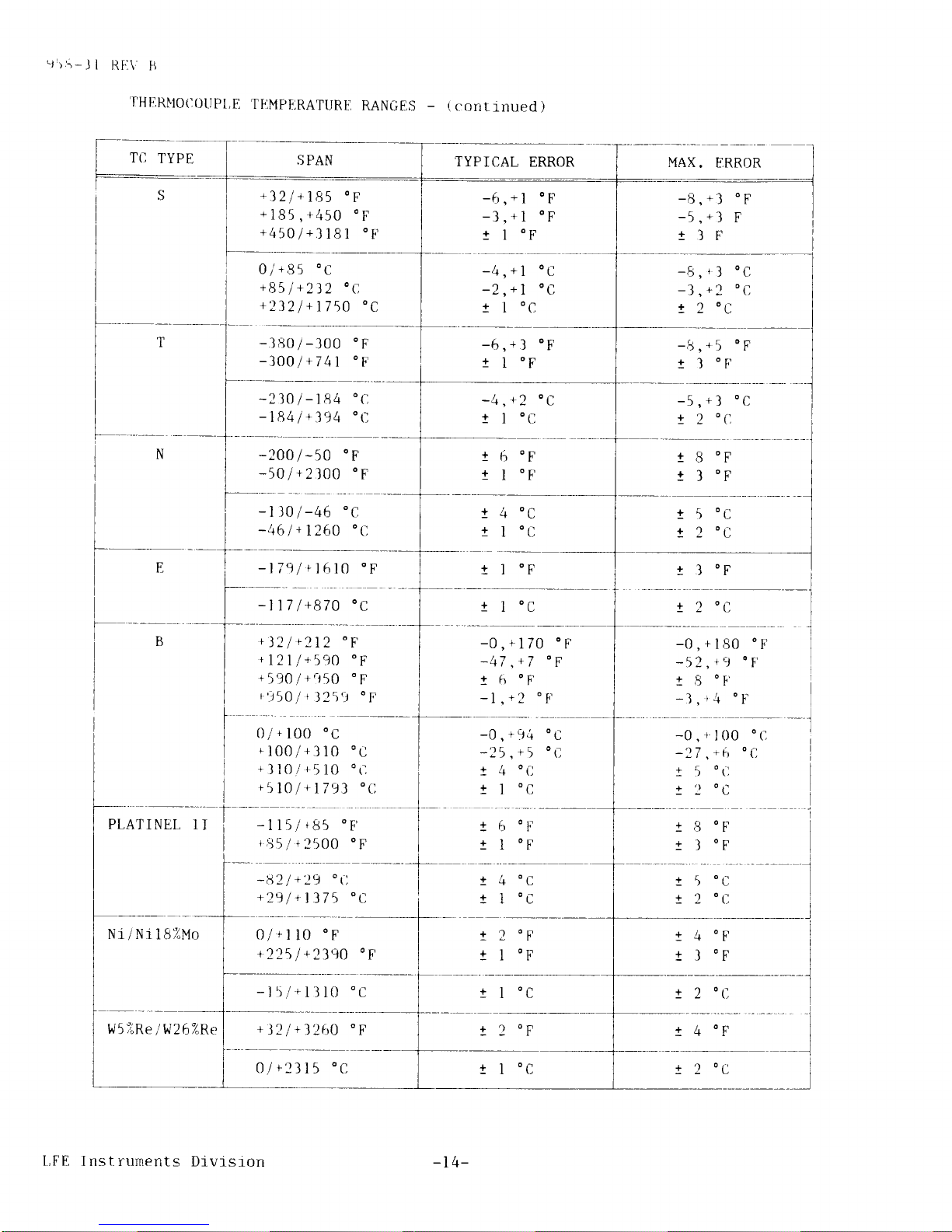
.fHII,RNIO(](JIIPI,E
TF]MPII,RATURE,
RANGES
-
(
contrnued
)
SPAN
TYPICAL
ERROR
oi*gl
oc
+B5
l
+2i2
'C,
+2321+1750
oC
-380/-300
oF
-3OOl+741
oF
-2]O
I
-184
-184
I
+394
-200/-50
oF
-501+2100
'F
-t
t0/-46
'c
-461+126O
o(l
-1791
fl
610
oF
-6,*1
oF
-l
+l
oF'
t I
oF
-4'*7
oC
-2,*7
oC
1
I
oC
r)
r
t:
t,
o^
(,
6
"F
I
"F
4'c
I
'c
t I
oF
6
"1.'
I
oF
.+ (,
1
0,-
rlF
-A
4n
+
I
oC
+)
oc
or-
I
l
L
!
-A'r5
oF
t I
oF,
o(l
,+l
oc
2
'(,
5
0c
2
0c
1
+
?
+
,)l
3
"F
t 3
0F
I
-117
l+870
oC
! 2
0c
+ l1/ 1111
otrr
').t
LrL
+121/+590
oF'
+\9Olr.J50
.F
t't\Ol1l25'l
"f
0/+100
'c
+100/+310
oC
+ll0/+510
oC
+510/
t1793
'[]
-0,+170
oF
-47
,+7
'F
t
fr
ot'
-l
1')
oFr
-0,+94
-lr5
+5
I
4
"C
!
I
oc
-0,+180
oF
-52,
t9
'F
t 8
0F'
-3,r4
o!'
-nr
,\a
t5
tl
100
+6
o
tl
OC
OC
'C
-115/
t$5
oF'
rB5/+2500
oF
t .9
ol'
t I
oF
I
+
I
OD
r
-82
l+
29
'fl
+291 +1375
oC
0/ f l
l0
'F
+22\l
*2390
oF
-15/tlll0'C
+)21+1260
oF
OC
t 4
"F
I
I
l
--l
t,FE
Inst-ruments
Divisrorr
-t
4-
! 2
0F
t 2
0c
'J)3-ll
til-\ lt
THF
RM(I(jOUPI
!-.
TFIMPERATLTRE
RANGES
_
(
cont
inued )
]'(I
TYPE
SPAN
TYPICAL
ERROR
l{l,"lRe
lvt2SiRe
MAX.
ERROR
+321+225
oF
+22513260
0F
+3'21
+107
o
C
+
107
I
+2
)40
*2240
I
+2)l
I
-R
+?
oF
!
2
0F
-5
t
t
l0
,
+d
o
F
4
0F
t,
OC
+l
OC
t,
-A
+1
oa
! 2
0c
t
6
0c
-j
I
l
W i W2
6%Re
+321+220
oF
+2201+480
oF
t4S0/l2rr0
oF
l
-0,+
!12
13
I nn o I.'
r
r
+110
0F
5
0F
r
0/
r
104
'c
+lO4l+249
"C
+2491+2115
"C
-0
t
t
+55
0C
t,
OC
,
+b0
I
o[]
)
(,
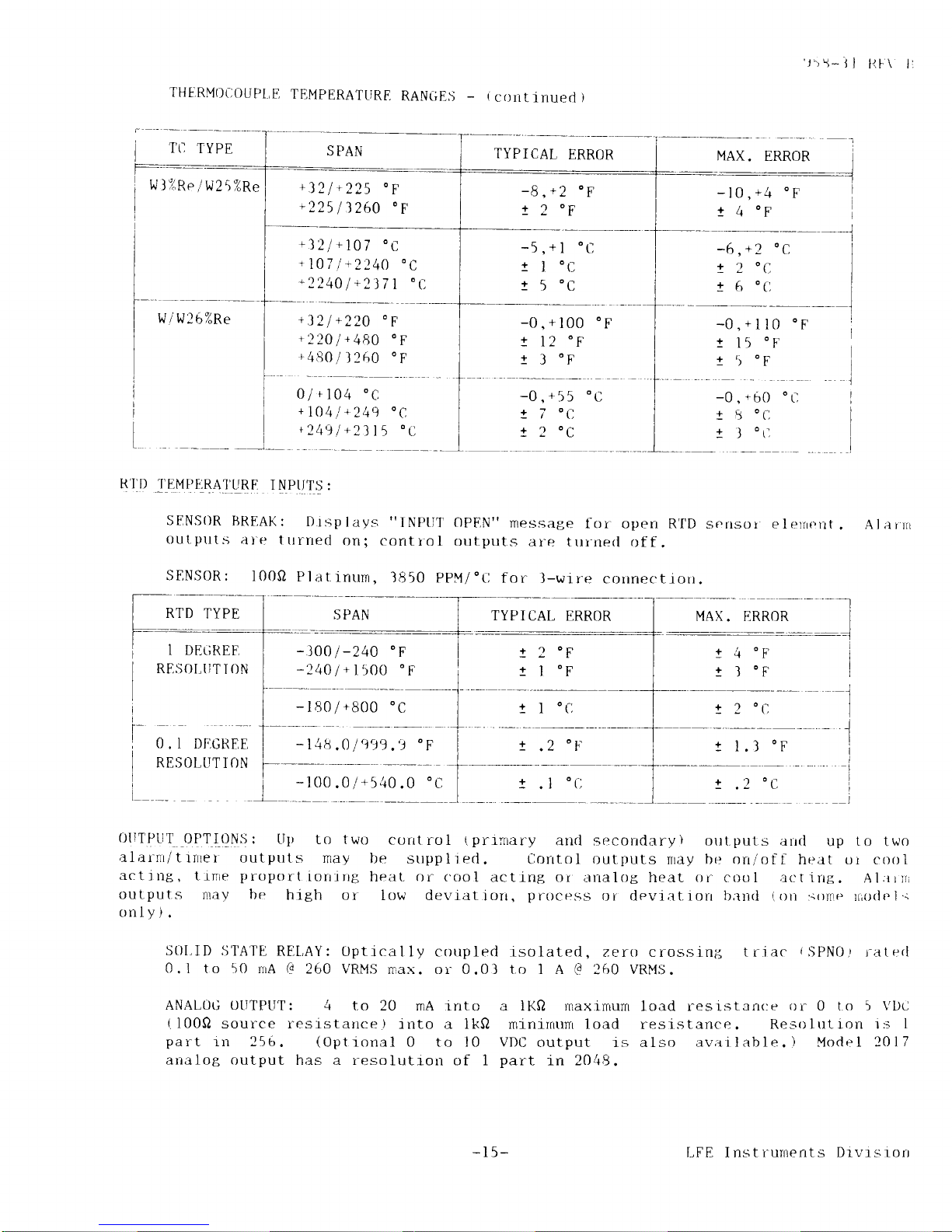
SENSoR
IJREAK:
Dtsplays
"INPtll'oPF,N"
message
for open R'I'D
sensor elr-'rnent
out
put
s
ai'e I rrrrred
on;
cont
ro l outputs
at"e
t rrr-ne<l
of f
.
SENS0R:
100s1
Plar.rnurn,
1850
ppM/"Ll
for
l-wire
connectiorr.
RTD
TYPE
MAX.
ERROR
Alainr
I DF]GREF,
REST-}I,tiT
T ON
O
.
I DF]GREE
RESOI-IIT I {]N
--l
_l
! 4
0F
t I
oF
RORER
I
(l
ol.
o
1
2
I
I
.t
.1
CPI
t
I
1
! 2
0c
t l.l
oF
!
.'2
oLl
(illrPllr
OPTI(]Nsj:
LIp
to two
corrt
rcll
tprrriar-y
and secorrdary)
orrl.puts alrd
up
to
two
alarnr/trrrter
outputs
nay t-re
strpplted.
tlclrrtol outputs
rrray
be orr/off
heat ol crlol
actitrg,
tinre
proport
iorrrrrg
heat. or
('ool
actir-rg or
irnalog heat
()r
cool a<'t irrg.
A.l
;rriri
ouLputs
nlay be
high or
iow der.latiorr.
procpss
or devi;rt.iorr b;rlrl
(r)n
:;olnr.
rriurl
el.r
only).
St)l.ID
S1'ATE
RFlt,AY: Optrcal
ly coupled
0.1
to
50
rrA
@
260 VRMS
max. or-0.01
ANAL0rl
OIITPLIT: 4
to 20 mA rnto
(
100Q
source resistance )
into a 1k0
part
in 256.
(Opt
ronal 0 to l 0
analog
output has a resolution
of 1
rsolated,
?.ero crossint
triac
rSPNO.t
i^aterl
to 1 A
(q
?60
VRMti.
a
IKQ
naxrmum load res istan<:e
or 0 t o 5 \'De
mlnrrnunL load
resi
stance
.
Reso ltrt ron r.'s
I
VDC
output 1s also
av;ri I able. ) Model 2017
part
in 2048.
-15-
I-FE
Inst
rurnerrts Drvrsrorr
'J5\-JI
RL.\ ti
OUTPUTS
(
contrnued
)
AI,ARM/TIMER
REL,AY:
SPDT
rated
1 A
G
I20 VRMS,
non-
inductrve.
up fof
tfme
in
minutes/seconds
or
hours/ninutes.
TqNlllc
PAMME_TE&S:
These
pararneters
are
loop
usitrg
a
security
coded
sequence.
accessj.ble
through the keypad
rn the tune
Trmer may be set
Proportiorrrng
barrd:
Adjustable
in l%
steps
secondary
outputs
have
separately
specifred
self
ttrne
2005
have
this
range
in manual
self
turring
prirrrary
output
only.
)
Reset:
Adjustable
in
.01
sl.eps
from
0.01 to
secondary
channe
ls
have
separate
set t lnts
.
actron
off.
Rate:
Adjusl,able
in
.01 steps fron
0.01
channels
have
separate
set-tings.
A
valr_re
Cyc1e
Ttnre:
AdjustabIe
in I
second steps
On/of
f Dead
Barrd:
Adjrrstable
in
steps of
f rom I Lo 2OO%
of span.
Prinrary and
PR bands
.
(
Mode ls
200 3 , 2004 and
tuning but are lrmtted
to 0-50%
for
20 resets
per
A
value
of
mtnut e
.
zeYo I ll
I
Prirnary and
ns
the
ieset
to 5
rninutes. Primary
of zei^o turns
the rate;rc
from 1 to
60 seconds
per
O.25,0.5
and
17. of
span.
and secondary
tion off.
cyclr:.
{uf_o1lg!!!{_!:
cont
ro I
.
Bumpless
transfer
algorithm
used to
lTlove f rom manrral
to
automat ic
AIrAeU
QEAD
tsaND:
0.4i(,
of
span.
|fl(llNI_R_EIO!q_!I0N
AND
C0INitIDENCE:
rl count.
nllTI
BEfnT
IdITDUP:
Reset.
is rnhibited
when the
process
variable
rs outsrde
of
the
pltts
and
mlnus
one
proportlonrng
band,
centered
at set
point.
Magnitude
of
the reset
actloll
rs
lrmtted
to
keep
the
process
varrable
wrthin
the
proportfonrng
band.
E4{P
4liq
U4L9P-E84TIQI!:
Nurnber
of
ranrp
serments
and tirne
intervals
are
as
descrrbed
by
the
nrodel
descr_iption
(see
Section
1.6.1).
Ramp
and soak
irrtervals
may be
ser
up
to erther
99
hours/ 59
rninutes
or 99
mlnutes/59
seconds.
Assured
soak
js
selectable
by the
tlsPt.
Cycle
repeat
may be
either
set
for continuous
or
from I to
255 complete
cycles.
qUl-.LlNllllt
Ql-EqALI0I:
Characterizes
the
load by
measurjnB
the
response durrng
start
up.
Self trrning
operates
only
on
primary
heating
outputs and with
PID constants
lrnLrted
as
f ol1ows:
F'ropoi-t
iorrirrg
Il;rrrd
-
1
Reset
-
0
to 10
resets
Rate
-
0 to
I rnlnutes
If
t-he
calcul;rtecl
values
fal
to the
appr-opriate
1imit.
Secondary'
['TD cor.tstatlts
are
LFE Instruments
D-ivisrorr
to 50
percent.
of span
per
minute
I outside
of the
above lirnits,
the constants
are clanrped
Values
outside
of these
values may
be entered rranually.
errtered
manual
ly.
-r6-
qQsiITIII
.caITBq!
qABAyEIq$:
Increase
ancl
decrease
solrd
stare
retays
to
operate
the
external
motor
operator.
A
standard
controller
nray
be
1000Q
slrdewire
ior modified
io,
.,."
with
a
l00o
or
1350
slrdewire).
deadba.d
is
selectabre
from
0.0
to
25.5
percent
of
span.
controrler
will
slldewrre
connections.
slidewr-re
calibration
can
be
either
rnanual
autorrratic
slidewrre
calrbratlon
routrne.
'lr5-ll
RI-\'
',
are
pi-ovjded
used wtth
a
Drrve
rrni
t
detect
operr
or
a rrrritlue
qqryu.t'l-Il4.Tl_!l\Q!!!oNs:
A11
Series
2000
controtlers
excepr
mortel
2005
rriay
be
supplred
wittL
oreital
cornnunicatrons
optfon.
Baud
rate,
parity,
harrdshake
pararneters
and
unrt
nurnber
are
settable
with
internal
DIP
switch.
Host
computer
firay
read
ancl
wrrte
nrost
operatrng
pararneters.
connections
f
or
cornrnunication.s
are
t,hrough
rear
25
plll
"D"
connector'
(Ref
er
to
the
instal
lation
rrranual
f or
nore
detai
1s or
(.r)rTr-
nrtttt
jcatlons
operatrotr.
) The
f
ol
lowing
communicatron
rnterf
aces
are
avar
labl
e:
1.8
RS2l2
RS422
Isolated
4l'5quBr,!
DrAqB4ry
rsolated
or
non-isolated
rsolat
ed
or
rrorr-isolat
ed
20
mA
current
loop
Fl6tlre
l-l
1s a
trrechanical
assembly
dragranr
of
the
serres
2000
r:orrtiol
lers.
,l.Lns
exploded
vrew
of
the
Serles
2000
controller
shows
the
f ive
nra
jor
subasseinblres:
the
citse,
the
f
ront
bezel
assernbly,
the
jnput._orrtput
(f
/0)
board,
the
cent
ral
proc.essor
tlnlt
(cPLI
)
boartl
artd
thr:
center
commlrnrcat
jons
or
opt-1ons
boarrl
. The
2000
,spr
rcs
corrti'ollers
have
been
deslgned
so
that
the
entire
electronjc
asembly
can
lle
easrlv
t
t-'tttoved
f r-orrr
t'hP
c;rsr:
by
presslng
the
tabs
on
the
sides
of
the
beze
i
ancl
prrl
I
irrg
t
he
as.sr:rnttly
frtrward. (Refer
to
Sr-ctron
1.10.
)
The
rlo
and
CPll
board
a.ssenrblies
are
e;rsily
remclve:<-l
from
the
bezel
asssnrfrly
by
releasing
the
sprlng
1o;lded
c1rp.s
fronr
the
notches
and
pulJrng,
the
bo;rrds
o.t
ol'
therr
connectors.
The
comnLrtnications
or
accessoi^y
board
may
be
rerroverl
try
f
i r sl
discotrnectf
rlg any
leads
and
cable
connectors,
renroving
the
sci-ews
ancl
sp.tcer
s
I lrat
hrl1d
t'he
boards
tclget-her
near
the
rear
of
the
board
and
pullrng
the
boarcl
Out
ol.its
edgecard
conttecl
or.
The
bezel
assembly
can
be
drsassembl
ed
by
renrovirrg
t
lre l wrr
sci'e\ts
at
the
bott'orn
of
the
hezel
assenrbly.
Most
modifjcatrons
descr-jbed
ir.r 11rrs
In'tnu'-rl
do rrot
retluire
any
changl's
to
the
bezel
;rssernbly.
However^,
r.t
lrr;ry l)r,
!r(J('essnry
to
disassenrble
thrs
part
for.servicjrrg.
I
.,i
ITqARD_
!!lul_cuB4_'rlQr!
I'he
Lwo
circuit
brtarcls
oI
t.he
electronic
assernbly
that
may
requrrr:
modrf
rcat
lsrr
;rr-r,
the
itlllttt-outptlt.
(rlo)
arrd
the
central
processrng
(cPU)
boards.
Sorne
r"rrodit'rcr;lt
iorrsr
retlu't
t'e'
actlraL
compcrnertt
changes
and
changes
to
the
circuit
boards.
ot
lr.r
niodilrc:ations
reqttrre
orrly
a
reprograrnming
or software
configuratiorr
ch;rrrge.
All
srlltwaie'charrges
nray
be
accompljshed
through
the
keypad.
Each
board
has
provlsrorrs
for r'leslgnated
otrLput
functlons
as
shown
rrr
Flgure
l-2,
Ther-e
ca'
br
o'l'
rrer
pr
inrary
output:
either
a
solid-state
relay
(SSRI
)
or an
analog
output
ri\NAl ).
Thei-r:
c;ll1
olllv
be
one
second"ary
otttput:
erther
a
solj-d-state
relay
(SSR2)
rlr
;rrr
;rnalog
0utput
(ANA2).
'Iite
Mt)D
CENTER
can
add
SSR2,
but
cannot
add ANAI
or ANA2
to
the Series
2000
st
ockerd
tltrit-s.
The
analog
otlpttts
can
only
be
provided
by
the
factory
or fronr
stockeci
rrrrjts
that
were
ordered
with
analog
output(s).
Alarrns,
indicated
as
ALMI
and ALM2;tie
provrded
as
statrdaid
on
models
2010,2011
and
2012.
ALMI
is
standarri
on
nodels
2011,
2014
arrd
2015.
0n
all
other
moclels,
alarms
are
optional
anrl may
be
adcled by
the
M3D
CENTER.
-t7
-
LFE
Instntnents
Division
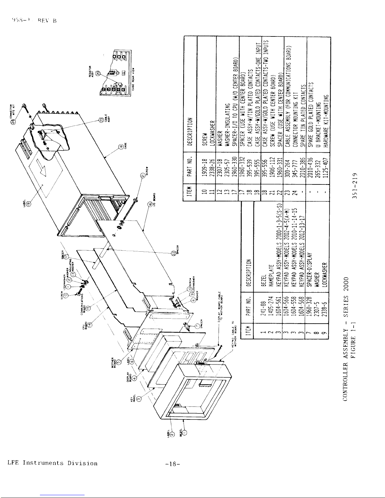
z
a
e
G
q
U
o
e
-
<
-=
6
d
<
o
-
o
-
@>
za
<o
-
@O
z\
ll
Eee
@@<
<<a
--@
=
a
=
-
a
<*:
ozo
6AO
O
e6
U6U
-><
U<J
aJc
-o
*-J
HHO
-Fg
u->>>
e<<
<@@
a<<
-
z
O
-
<^O
F6e
-e<
O<o
oo6
6e
<F-
J-W
OUO
AH-
\-
-u
>a-
@-v
<u
-U
UUO
@E<
<od
o
-
O
<
-
-6
-
-a
OF<
--
ooo
LvH6
>->
J-<
@OJ
--c
6e-
@o<FF
O
J-e
6-<
<OC
oa@
<
-9
O-
eF
a-UHFEO
<-J-
|
OOF
-H
OUU
9Yg
O<
u<<@e
d<
@--
O
-
e
<
@€
q@
O6
66
O
@N-
Nbo
OO€
tqb
=t
o6r
>qo
@+-
.Q€
-6O
Nr I
rro
Oo.<
OSQ
€
6NQ
ot6
o€<
-
QH
\@@
@dN
dNN
;t
rai
d9;
o:
?-
e+
I J'
-
O
a
O
o
O
-
JO
Jd<
UUd
N->
6ZV
-d
NQN
Q<<
ooa
UUU
o6A
ooo
---
606
<<<
aoc
<
J
o
@4
de<
UUo--
c<o
A-J
o
-
c
N€
.<oo
@@@
ooo
@@€
@
ON@
€o6
-
N@6
9!5-
)
RF.\'
B
ct
I
J
z&
u)*
<k-
J
J
a-
F
z
(J
-
---@$
Yt
t[n
-
18-
LFE
Instruments
Division
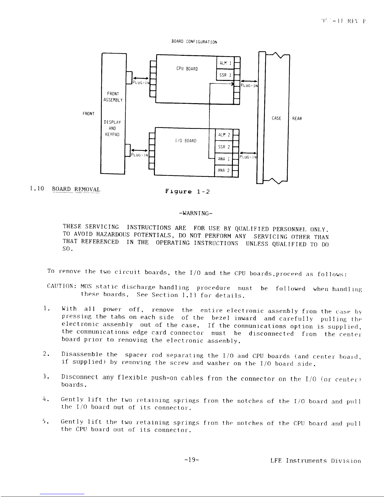
CPU
EOARD
FR0t/
T
AS
STIlBLY
D
I SPLAY
AND
KE YPAD
','
-
] I
RI.\
P
FRONT
I.l0
BOARD
REMOVAL
BOARD
CONFIGURAIION
Frgure
1,
-2
-I.JARN
I NG-
THESE
SERVICING
INSTRUCTIONS
ARE
TO
AVOID
HAZARDOT]S
POTENTIALS,
DO
THAT
REFERENCED
IN
THE
OPERATING
s0.
FOR
USE
BY
QUALIFIED
PERSONNEI,
ONLY.
NOT
PERFORM
ANY
SERVICING
OTHER
THAN
INSTRUCTIONS
UNLES,S
QI]ALIFIED
TO
DO
To
remove
t,he
two
circuil-
boards,
the
I/0
and
the
CptJ
boards,proceed
as
follows:
cAtlrI0N:
MOS
statrc
discharge
handling pr-ocedure
must
be
these
boards.
See
Section
l.ll
for
details.
fol
lowed
when
handl
ing
'
Wrth
al
l
power
of
f
,
remove
the
entire
electronic
assernbly
f ron
the
c:;rse
by
pressirtg
the
tabs
on
each
side
of the
bezel
inward
ancl
carefulIy pulling
the
electronic
assembly
out
of
the
case.
If
the
communicatlons
option
is
suppliecl,
the
communications
edge
card
connector
must be
disconnectr:cl
from
the
cenrer
board
prtor
to
removing
the
electronlc
assembly.
.
Drsassenrble
the
spacer
rod
separattng
the
I/0 and
CptJ boards
(and
center
boarcl
.
lf
supplred)
by
rernoving
the
screw
and washer
on
the
I/O board
sidr:.
l.
Disconnect
any
flexible
push-on
cables
from
the
connector
on
the
I/0
(or
cenrer
r
boards.
Gently
lrft
the
two
retaining
springs
the
I/0
board
out
of its
connector.
Gently
lift the
two
retainrrrg
springs
the
CPtl
board
out
of
its
connector.
from
the
rrotches
of
the
I/0 board
and
prrl
I
fron
the
notches
of the
CPU board
arrd
pul
I
-
l9-
LFE
Instruments
Dtvlsrorr
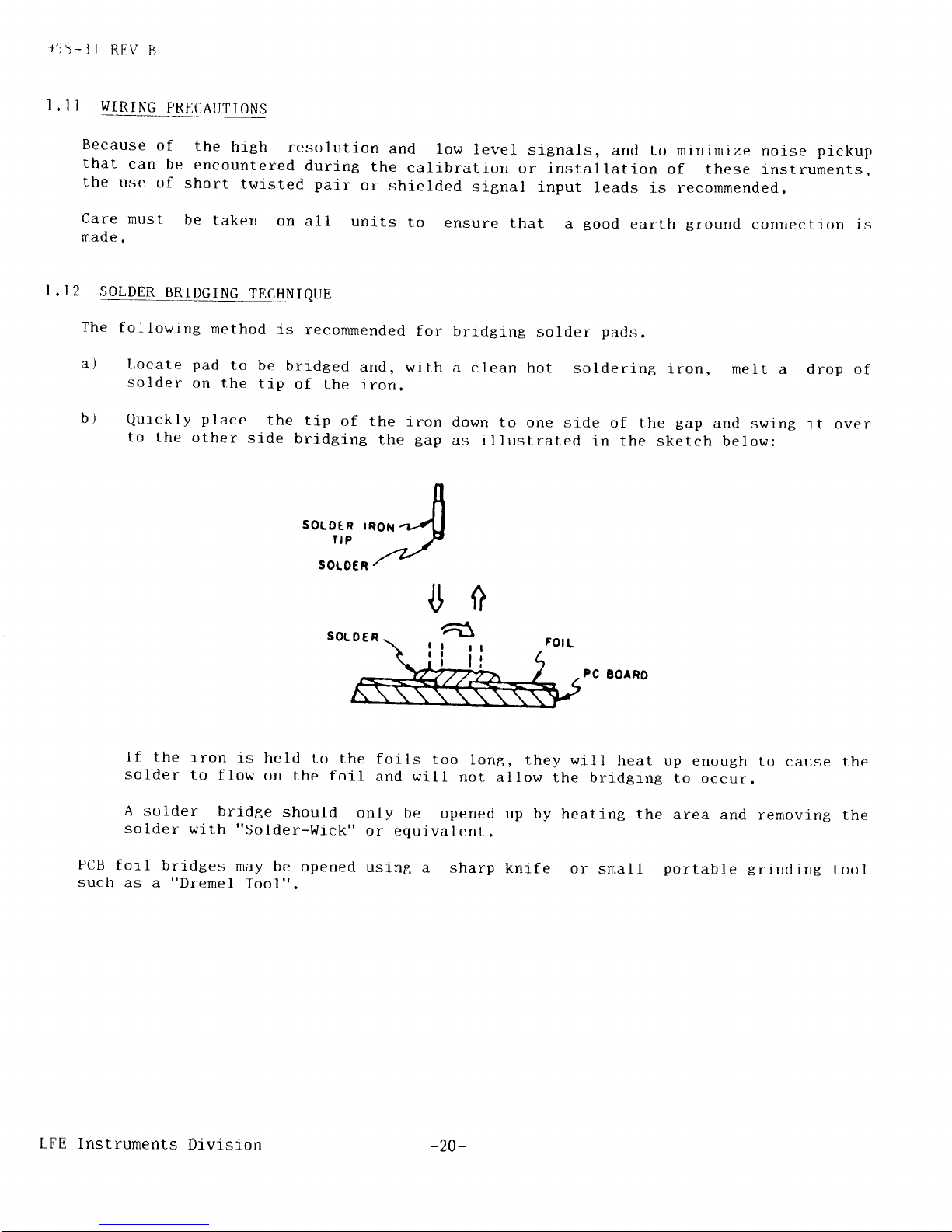
'J5)-ll
RI.IV
ii
l.1i
WIRING
PRECAUTIONS
Because
of
the
hith
resolution
and
low
level
signals,
and
to minimize
noise
pickup
that
can
be
encountered
during
the
calibration
or installation
of these
instruments.
the
use
of
short
twisted
pair
or
shielded
signal
input
leads
j-s
recommended,
Care
must
be
taken
on
all
uni.ts
to
ensure
that
a
good
earth
tround
connection
is
made.
1.12
SOLDER
BRIDGING
TECHNIQUE
The
following
method
is
recommended
for
a)
l,ocate pad
to be
bridged
and.
with
solder
on
the
tip
of
the
iron.
bridglng
solder
pads,
a clean
hot
soldering
iron, melt
ab)drop of
it over
Quickly
place
the
tip
of the
iron
down
to
the
other
side
bridging
the
gap
as il
to one
side of t
lustrated
in the
he
gap
and swlng
sketch
below:
SOLoER
I
TIP
soL0€R
PC
BO^RO
If the
tron
1s held
to
the
foils
too
long, they
will
heat
solder
to
flow
on the
foil
and will
not
allow
the brldging
A solder
bridge
should
only be
opened
up by
heating
the
solder
with
"Solder-Wlck"
or
equivalent.
PCB
foil bridges
may
be
opened
uslnt
a sharp
knlfe or
smarl
such
as a
"Dremel
Tooltt.
up enough
to cause
the
to occur.
area
and rernoving
the
portable grrnding
tool
LFE
Instruments
Drvrsion
-20-
t.ll
I'{Qj;]SIATIC
DISCHARGE
HANDLING
PRECAUTIONS
;::'r
CAUTJON;'r?,i
IN
HANDLING
MOS
INTEGMTED
CIRCUITS
AND
THE
UNI'IS
INTO T{HICH
THEY
HAVE
BEEN
INSTALLED,
SPECIAL
PRECAUTIONS
MUST
BE
OBSERVED
IN
THE
WORK
AREA
TO
PREVENT
STATIC
CHARGES
FROM
CAUSING
DEVICE
FAILURES.
The
precautlons
listed
below
are
recomrnended
to
:'
All
benches
used
for
assembly
or test
of
conductive
antrstat
i<: rnaterral.
j',\-]l
RF,V
iJ
rnrnfmf
ze these
fa'i
lures:
MOS
circuits
are to
be
covered
wrth
Conductrve
wrist
straps properly
that
body
charges
are
grounded.
grounded
should
be
worn
by
all
operators
s()
WARNING:
NEVER
EXPOSE
AN OPERATOR
DIRECTL,Y
TO
A HARI)
ELF]CTRICAI,
GROUND.
FOR
SAf
ETY REASONS,
THE
OPEMTOR
MUST
HAVE
A
RE,SISTANCE
OF
AT
I,EAST
1OOK OHMS
BETWEEN
HIMSELF
ANI)
HARD
ELECTRICAL
GROUND.
Antr-static
netttralized
srnocks
are vrorn
to elirninate
statjc
charges
generated
by
frrction
of clothrng
layers
during
normal
wear,
Cotton
gloves
are
worn
when
handlrng
MOS
devices.
Nylon
gloves
or
finger
cots
can
NOT
be rrsed.
Al1
MoS
parts
mllst
be left
in conductive
trays.
The
use of
plastic
containers
rs not
al
lowed.
The
use
of
a
conductive
foam
such
as Velofoanr
lt761l
is
suggested.
Solderlrrg
j
rorts
mrlst
have
grounded
tips.
At,tent ion
shoul d be
grven
to 11y
equipment
that
may be
rrtductively
coupled
t.hat
can
generate
stray
volt;rges.
MOS
parts
should
be
handled
on
grounded
conductjve
surfaces
and the
oper;rtttr
must
touch the
conductive
surface
before
touching
the
parts.
MOS
devi-ces
shotrld
not be
handled
by thelr
leads but
by thelr
packages
insteacl.
In
general,
materials
prone
to statlc
charge
accumulation
should
not corne
irrtrr
contact
wrth
MOS devlces.
-2t-
LFE Instrunents
Division
!5\-ll
RtrV
tJ
l.l4
cAL I q&{UoNl
TBQSELESH0OT
r NG
CONNECTORS
The
only
internal
potetttiorneter
adjustments
in a
Series 2000
controller
are for-the
4/20
mADC
and
0-5
VDC
analog
outputs.
In
these
cases, the
output
board must
be
accessrble
for
pot
adjustment
which
cannot
be
done through
the case. A
special
connector
assenrbly
(P/N
345-826)
consisting
of
the
rear
portion
of the case with
terrnrnals
installed
ls
available
for
cali.bratron
and
troubleshooting.
0rder this
part
from
the
factory
if
needed.
For
calj-bration
and
service
of
older
therrnocouple
input
controllers,
a
cold
junction
compensator
resistor
assembly
(P/U
344-1199)
can
be
ordered from
the
factory
to mount
orrto
the
rear
terminals.
Each
particular
resistor
rnust
stay with
the
controller
as a
set
after
calibration
in
order
to
retain
the
original
caljbratron
accuracy.
Al
l
older
MOD
controllers
are
factory
supplied
wlth
this
assembly.
When
rnodrfying
a MoD
control
ler
for
non-thermocouple
rnput,
this
assembly
must be
removed.
Newer
controllers
have
the
cold
junctlon
compensating
resjstor
rnounted on
the
I/0 board
anrl
this
paragraph
does
not
apply.
LFE
Instruments
Drvisi-on
-22-
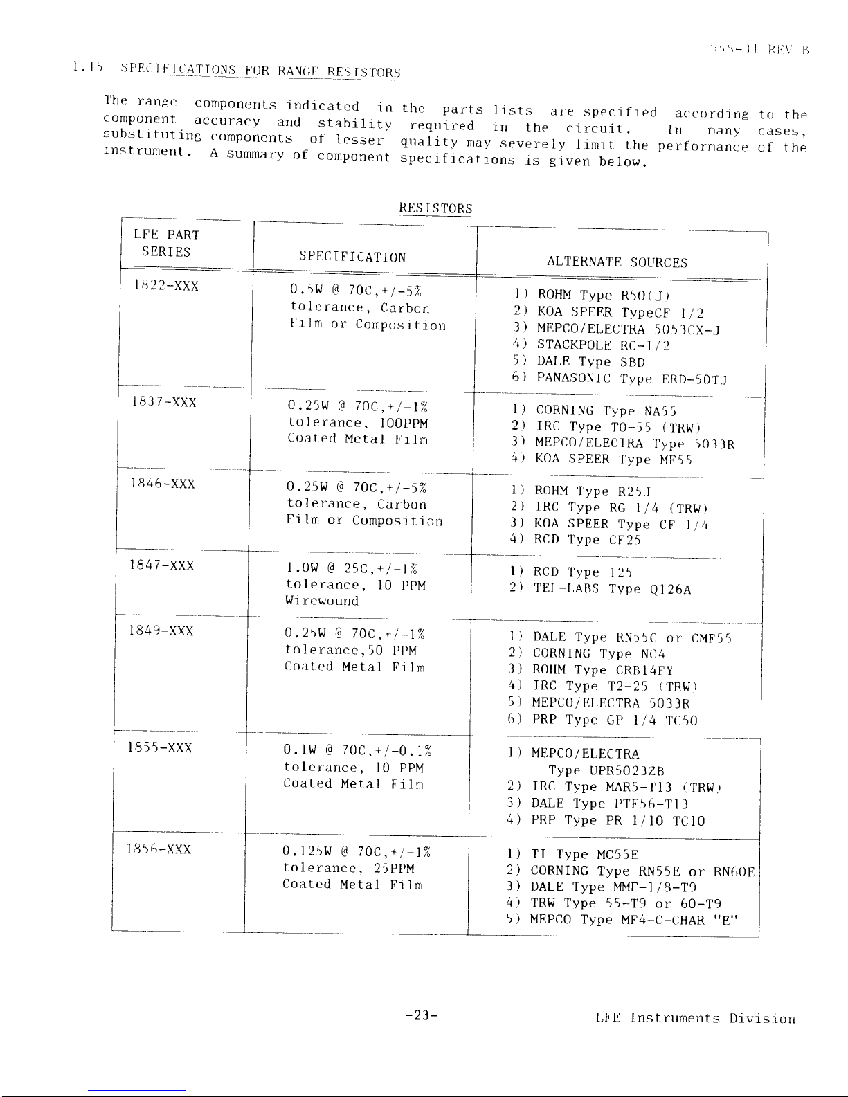
l
.
l 5
!FlEllli
l_q4IIOr\S
FOR
RANGE
RF.s
i.s
f{lRs
T'he
range
conrporrerrts
rndrcated
in
component
accuracy
and
stabi
ll'ty
substrtuting
conponents
of
lesser
rnstr^ument.
A
summary
of
component
'r,r*ll
Hl.'\'
ti
are
specrf
I
ed
accorclirrg
to the
crr-cuit
. In
fitany
cases,
ly
limit
the
perfornrance
of the
tiven
below.
the
parts
I rsts
requi
red
in
t
he
qualrty
may
severe
spectfrcations
is
LFE
PART
S ERI
ES
I
8
2 2_XXX
t8l7-XXX
I 846-xxx
1847-xxx
RES
I S
TORS
SPECIFICATION
0.5w
G
70t,,+l-52
tolerance,
Carbon
Frlm
or
Composit
ion
0.25W
(0
70C
,+
I
-lZ
tolerance,
l00ppM
Coat.ed
Metal
Film
0.25w
G
70C
,+
I
-52.
tolerance,
Carbon
Fi
ln
or
Cornposit.ion
1
.0W
G
25C,+
I
-tZ
tolerance,
l0
ppM
l.r/r
rewound
O,25w
G
70C,+l-t%
tolerance,50
PpM
Coated
Metal
Film
ALTERNATE
SOURCES
ROHM
Type
R50
(
J
)
KOA
SPEER
TypeCF
I
I
Z
MEPCO/ELECTRA
505 ]CX-J
STACKPOLE
RC-I
/2
DALE
Type
SBt)
PANASONICj
Type
ERD-50'r,l
1)
?)
3)
4)
5)
6)
l)
2)
.tl
4)
CORNING
Type
NA55
IRC
Type
T0-55
(TRI,J
MEPCO/EI.ECTRA
Type
KOA
SPEER
T'ype
MF55
)
50llR
l)
tl
t)
4)
ROHM
Type
R25.J
IRC
Type
RG
1/4
KOA
SPEER
Type
RCD
Type
CF25
(
TRW)
CF
114
0.
ltv
G
70C,+
l
tolerance,
l0
Coated
Metal
RCD
Type
125
TEL-I,ABS
Type
Ql2bA
)
DALE
Type
RN55C
or
CMF55
)
C0RNI
NG
Type
N{)4
)
ROHM
Type CRBI4FY
)
IRC
Type.
T2-25
(TRl{)
)
MEPCO/ELECTRA
5033R
)
PRP
Type
GP
l/4
TC50
MF,PCO/
ELECTRA
Type
UPR5O23Zlt
IRC
Type
MAR5-Tl3
(TRW)
DALE
Type
PTF56-Tl
3
PRP
Type
PR
l/10
TC10
l)
2)
I 849-XXX
1855-xxx
I 856-xxx
-n
10/
PPM
Film
I
2
3
4
f
)
6
.t
)
1l
4)
0.125LJ
G
70C,+l-t%
tolerance,25PPM
Coat.ed
Metal
Fi.
1nr
I
)
TI
Type
MC55E
2)
CORNING
Type
RN55E
or
RN60E
3)
DALE Type
MMF-I18-T9
4) TRI.J
Type
55-T9
or 60-T9
5
)
MEPCO
Type
MF4-C-[]HAR
"8"
-23-
LFE
Instruments
Drvlsron
 Loading...