

LF-B CT26-15 User Manual
USER MANUAL
CT26-15
THIS MANUAL CONTAINS IMPORTANT INSTRUCTIONS FOR SAFETY AND
OPERATION.
At the end of this manual:
YOUR WARRANTY CERTIFICATE
«Model complies with safety requirements»

Manual CT26-15 - LFB
3
CONTENTS
1. PRESENTATION........................................................................................................................................5
2. SETTINGS / INSTALLATION..................................................................................................................6
2.1 Saddle settings ........................................................................................................................................6
2.1.1 Angle.............................................................................................................................................6
2.1.2 Height............................................................................................................................................6
2.2 Handlebar adjustement
(handlebars and stem)
.......................................................................................7
2.2.1 Height............................................................................................................................................7
2.3 Brake adjustment.....................................................................................................................................8
2.3.1 Front brake Type V-Brake..............................................................................................................8
2.3.2 Rear Brake Type V-Brake..............................................................................................................9
2.4 Luggage carrier......................................................................................................................................10
2.5 Assembly and disassembly wheels
(rear wheel by specialist)
...............................................................11
2.5.1 Front wheel..................................................................................................................................11
2.5.2 Rear wheel...................................................................................................................................12
2.6 Lighting.................................................................................................................................................15
3. USE OF AN EBIKE....................................................................................................................................17
3.1 Change speeds indexed..........................................................................................................................17
3.2 Change speeds electronic......................................................................................................................17
3.3 The battery meter ...................................................................................................................................18
3.4 The electric assistance...........................................................................................................................18
3.4.1 Operation.....................................................................................................................................18
3.4.2 Performances...............................................................................................................................19
3.4.3 Technical specications of the assistance system........................................................................19
3.4.4 Starting and the locking of the battery .........................................................................................19
3.5 The electric motor ..................................................................................................................................20
4. BATTERY CHARGE.................................................................................................................................21
4.1 Charger..................................................................................................................................................21
4.1.1 Precautions
(safety instructions)
..................................................................................................22
4.1.2 Charger protection.......................................................................................................................22
4.2 The battery.............................................................................................................................................23
4.2.1 Safety recommendations with your battery ..................................................................................24
5. TIPS FOR INCREASED AUTONOMY ...................................................................................................26
6. CT26-15 MAINTENANCE.......................................................................................................................27
6.1 Maintenance..........................................................................................................................................27
6.2 Lubrication............................................................................................................................................27
6.3 Maintenance..........................................................................................................................................27

Manual CT26-15 - LFB
4
7. SAFETY – RECOMMENDATIONS........................................................................................................28
8. TECHNICAL DATA..................................................................................................................................29
9. EC CONFORMITY STATEMENT..........................................................................................................30
10. WARRANTY CONDITIONS............................................................................................................31
11. WARRANTY CERTIFICATE...........................................................................................................32
12. CONFORMITY CERTIFICATE......................................................................................................33
Manual CT26-15 - LFB
5
1. PRESENTATION
Thank you for choosing an ebike LFB.
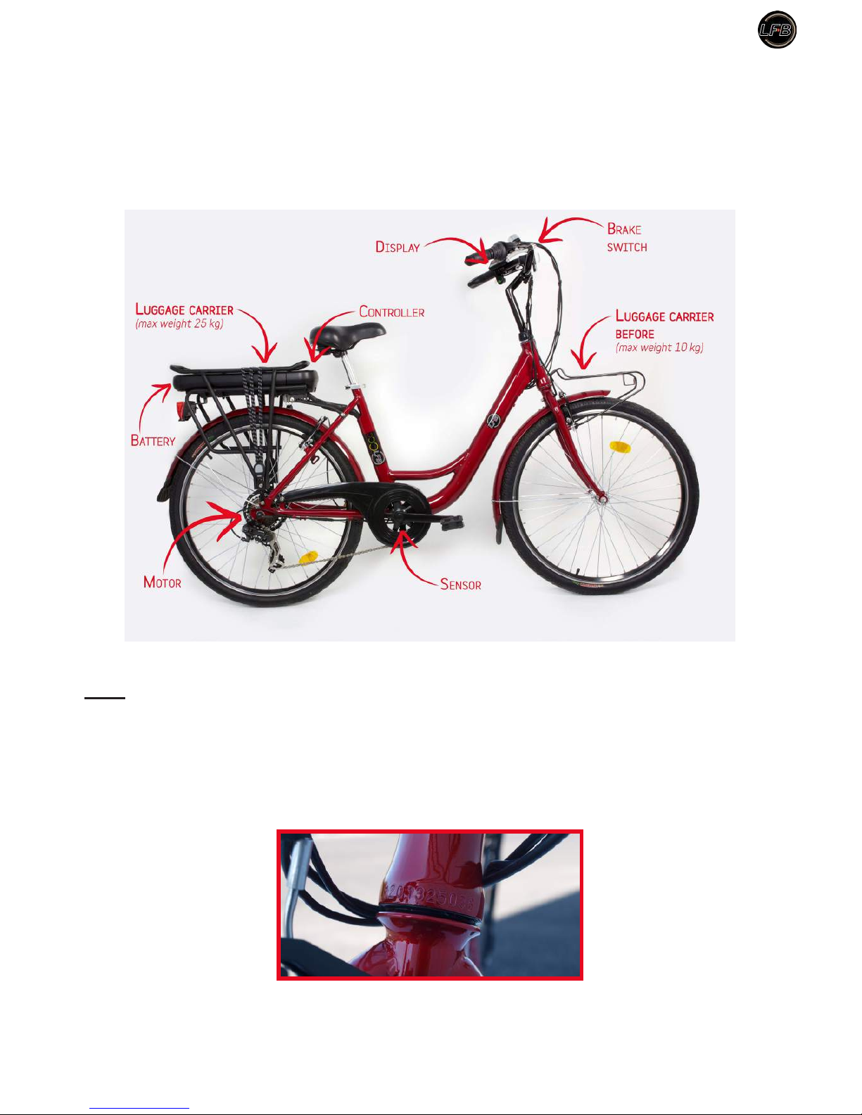
Presentation of ebike
Note:
• The sign r indicates important tips and mandatory safety measures. Follow the various instructions.
• Some adjustments, assembly / disassembly tool and require a particular skill; will perform as if you are
experienced, otherwise consult your authorized dealer or specialist.
• The sign indicates the tools that will be needed for setting operations.
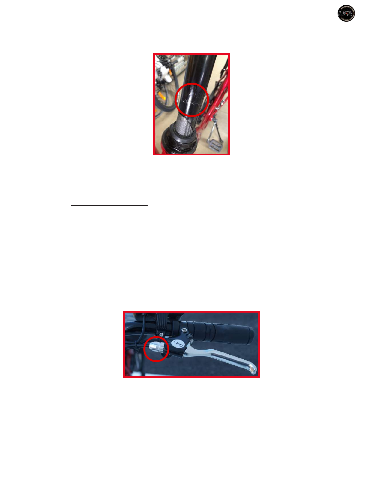
• Your electric bike has a serial number engraved on the frame just above the fork.
Serial number engraved on the frame just above the fork.
r
MaxiMuM load: 100 kg. For your saFety it is necessary to not put a load higher on the ebike when you are
riding it.
Manual CT26-15 - LFB
6
2. SETTINGS / INSTALLATION
r
adapt the bike to your size.
2.1 Saddle settings
Key 13 mm.
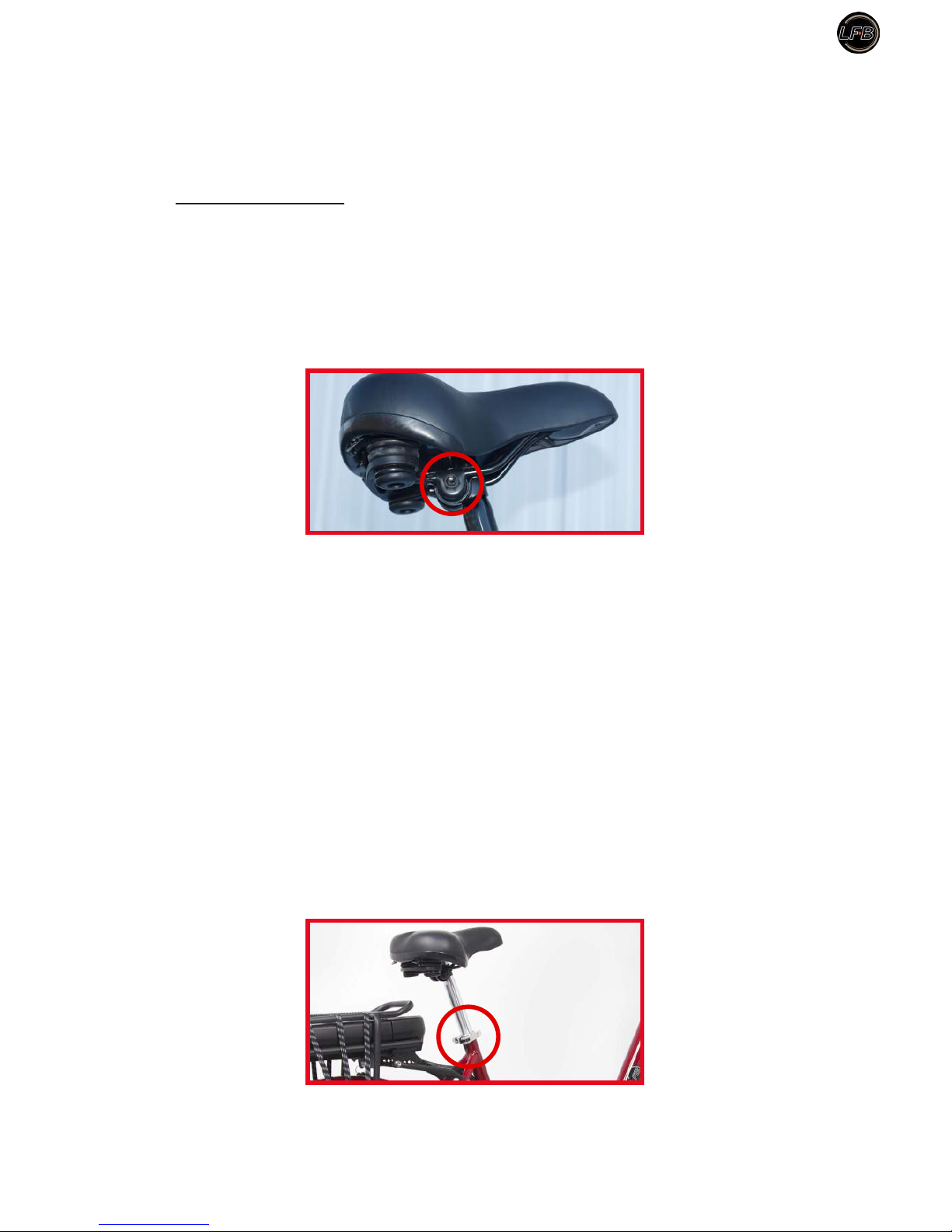
2.1.1 Angle
Nut.
Loosen the nut under the saddle.
Adjust the angle of the saddle, in order to get the best for your comfort position. Tighten the nut (tightening
torque 25 Nm).
2.1.2 Height
The ebike saddle enables a lower position than on a conventional bike. With the electric assistance you will
provide less effort and you can be sitted at a lower position for better safety. The required sizes of the user
(rider) for optimum use of the bicycle is between 1.50 and 1.90m. So, adjust your seating position seat height
according to the following indications:
Loosen the quick release of the saddle tube.
Quick release.
Sitting on the saddle with shoes suitable for cycling, place a pedal in the down position, place one heel on
the pedal, the leg must fall normally without being stiff. Raise or lower the saddle to get the correct height.
Manual CT26-15 - LFB
7
By pedaling backwards you should not wiggle.
To calculate the height, you can also the formula «saddle height» = 0.885 x «crotch». To measure the
crotch height put yourself barefoot and spaced beads ve centimeters. Place (without pressing too hard) a
stick against your perineum and then measure the height from the oor to the stick. You then get the value
«crotch».
Fasten the quick release.
r
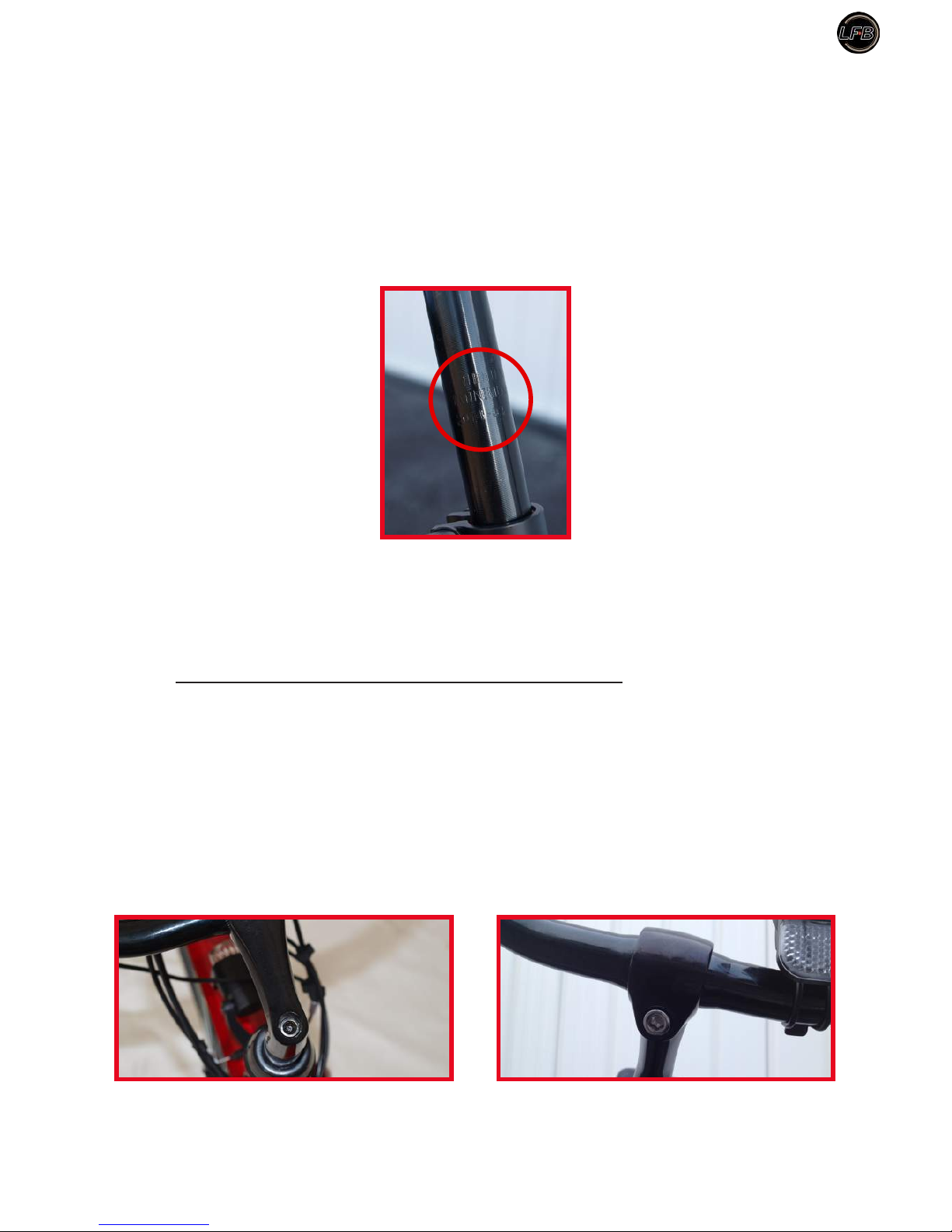
the saddle tube should not coMe out beyond the etched saFety Mark (vertical bars).
Safety Mark.
The minimum height between the highest point of the saddle and the soil is 80 cm.
2.2 Handlebar adjustement (handlebars and stem)
Allen key 6 mm.
2.2.1 Height
To be comfortable, the position of your handlebars should be at least at the same height as your saddle, or
more depending on your comfort. Unscrew the Allen screw and set the desired height of your handlebars.
Screw height adjustment. Handlebar angle adjustment screws.
Do the same with the second screw to adjust the angle of your handlebars. After adjustment, vigorously
tighten screws, maximum tightening torque of 25 Nm.
Manual CT26-15 - LFB
8
r
the steM should not coMe out oF the head tube beyond the engraved Mark (vertical bars and inscription
«MINIMUM INSERTION»).
After adjustment, tighten the screw by turning clockwise direction (maximum tightening torque of 25 Nm).
2.3 Brake adjustment
Allen key 5 mm.
Screwdriver.
2.3.1 Front brake Type V-Brake
The front brake is maneuvered by the left handle on the handlebar.
Fully tighten the nut on the brake lever, this feature allows you to compensate later the natural release of
the brake cable.
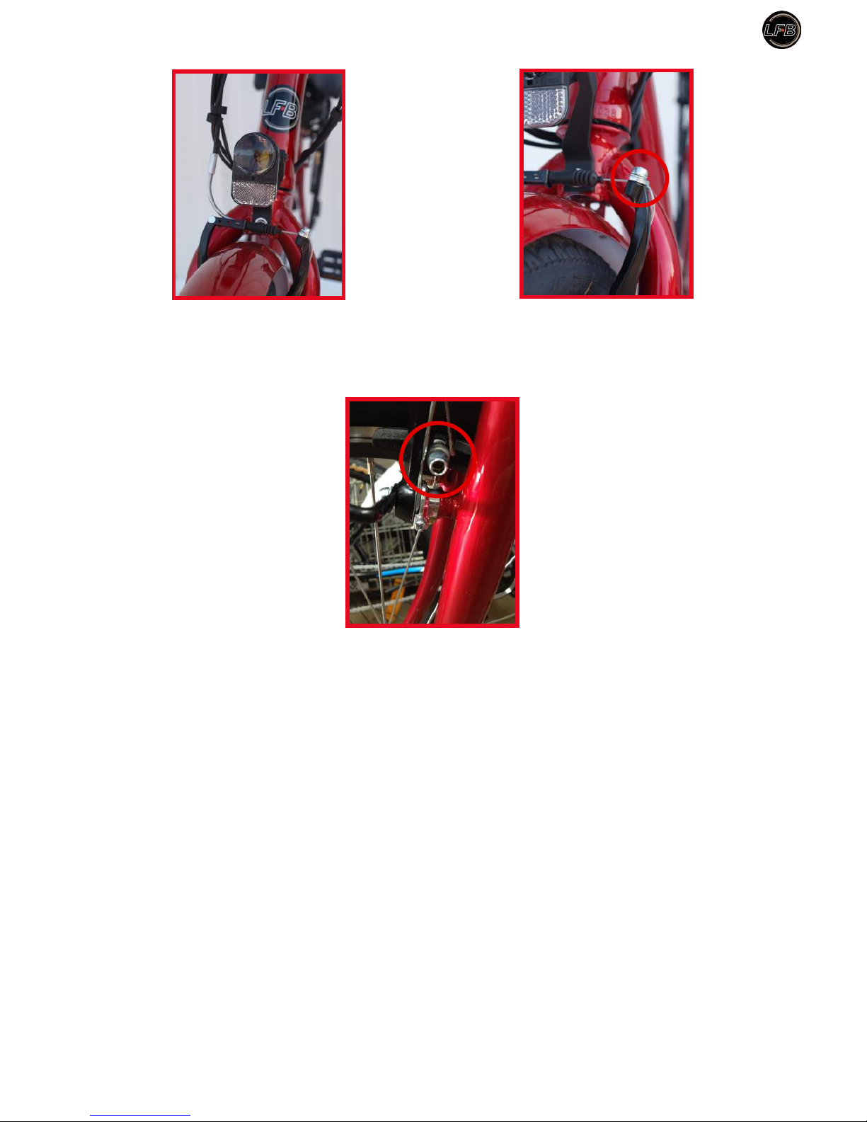
Loosen the cable clamp and pull the cable until the brake pads touch the rim. Tighten the cable clamp (special
attention is to be made at each end of the sheath which is to enter without forcing into the housing of each
rigid tip, brake lever and V-Brake).
Manual CT26-15 - LFB
9
The pads are properly adjusted when they are equidistant from the rim. The nal adjustment is to tighten
the screws mounted on brake holders with a screwdriver (distance of approximately 0.1 to 0.5 mm from the
rim).
Controlling your setting is correct when the wheel freely rotates and stops smoothly.
2.3.2 Rear Brake Type V-Brake
The rear brake is operated by the right handle to the handlebar.
As for the front brake (See: 2.3.1) fully tighten the nut on the brake lever, this feature allows you to
compensate later the natural release of the brake cable.
Loosen the cable clamp (See: photos of the front brake control) and pull the cable until the brake pads
touch the rim.
Tighten the cable clamp (special attention is to be made at each end of the sheath which is to enter without
forcing into the housing of each rigid tip, brake lever and V Brake.)
The pads are properly adjusted when they are equidistant from the rim. The nal adjustment is to tighten the
screws mounted on shoe holder with a screwdriver (distance of approximately 0.1 to 0.5 mm from the rim).
r
warning! when rainning or on wet surFaces, the stopping distance increases.

Manual CT26-15 - LFB
10
2.4 Luggage carrier
r
do not charge More than
10 KG
on the
FRONT CARRIER.
r
do not load your
REAR CARRIER
More than the value indicated:
25 KG.
All devices device or luggage installed by you on your carrier (child seat - other luggage, etc.) must be
compatible with the geometric characteristics and resistance of the bicycle.
r
you Must periodically control that the screws Fixing the carrier are tightened. this type oF carrier is
not designed to tow trailers.
Any changes made on the carrier by the user will engage its own responsibility.
When the carrier is loaded, cycling behavior changes are to be considered (wind stability, braking distances,
changing directions etc ...). For his safety, the user must be aware of these behavioral changes.
When installing a child seat or saddle bags, a security control is required (straps dangling, danger-taking in
the rays, fall to fear, seat xing child to check stability, risk pinch of the ngers of the child under the saddle,
etc.).
The reector and the rear trafc light should not be hidden by luggage or seat attached to the carrier.
The load on the luggage carrier shall be distributed on each side thereof in order to ensure stability during
movement on public roads.
Manual CT26-15 - LFB
11
2.5 Assembly and disassembly wheels
(rear wheel by specialist)
2.5.1 Front wheel
Wrench 15 mm.
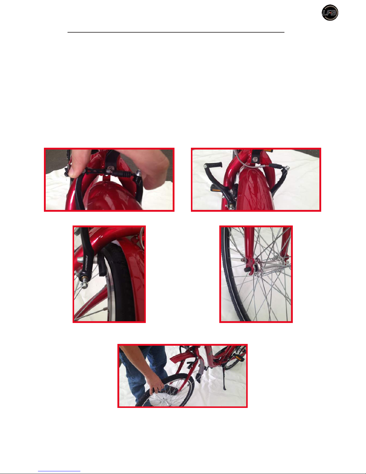
Disassembly the front wheel :
You must rst loosen the cable clamp of the V-Brake to release the pads in order to remove the wheel. Loosen
the nuts on each side of the axis of the wheel and release the washers.
Lift the bike and lightly hit the top of the tire to clear the wheel.
Loosen the cable clamp brake V-Brake.
Released pads.
Loosen the nuts on each side of the axis of
the wheel.
Lift the bike to remove the wheel.
 Loading...