

Lezeti ACDC12B Installation Manual
INSTALLATION GUIDE
MODEL: ACDC12(B)
© 2015 CLIMA-TEKNOLOGIES, LLC
Version 1.0

ACDC12B Solar Air Conditioner Heat Pump
Installation Manual
Before installing or using your solar air conditioner, please print and read
this manual carefully and keep it for future reference.
Notice To Owner/Installer
This unit is designed for easy installation by an experienced person. It is legal for a
homeowner to install it, however we highly recommend using a licensed HVAC
technician for installation.
Legal Information About Self-Installing R410A Air Conditioners
A homeowner with a vacuum pump, proper training, and equipment can install this unit. Unless you are
experienced with installing air conditioners we recommend you hire a professional installer. The person who
installs the system must do all work in compliance with local building and electrical codes.
Are there any restrictions on the purchase of R410A refrigerants?
R410a is not an ozone-depleting substance. At this time the purchase of R410a refrigerant is not restricted in the
US. There is no technician certification requirement for those that purchase HFC refrigerants, such as R-410a or R134a. If you are not licensed, some local HVAC supply companies may refuse to sell you R410a based on a
misunderstanding of the law, or because they wish to discourage homeowners from working on their own
systems.
Are there any restrictions on the use of R410A refrigerants?
Yes, it is illegal to knowingly vent or release these refrigerants. The venting prohibition applies to R410a, and all
other HFC refrigerants, just as it does for ozone-depleting refrigerants like R-22.
Is EPA technician certification required to service R410A systems?
No, at this time EPA technician certification is not required in order to service R-410a systems.
Source: http://www.epa.gov/ozone/title6/phaseout/technicians_contractors_faq.html
Please read this installation manual completely before installing the product. If the power cord is damaged, replacement must
be performed by authorized personnel only. Installation work must be performed in accordance with the NEC and local codes.
You should contact a licensed service technician for installation, repair, or maintenance.
Improper installation could damage the system and/or void the warranty and could result in injury, death, or property damage.
Version 1.0
© 2015 CLIMA-TEKNOLOGIES, LLC
1
INSTALLERS, Please read the following warnings to prevent
voiding warranties:
WARNING: Make sure the PV panels are wired in PARALLEL, NOT SERIES. Verify voltage
is within range prior to connecting to the ODU DC breaker.
WARNING: Voltage from breaker box to ODU disconnect should be 220V (measured
between L1 and L2.) See page 13, figure 24.
WARNING: E1 – error codes, “lack of signal” - IDU is not receiving signal from the ODU.
(L1 and L2 lines may be swapped, reference Service manual pg. 32)
WARNING: Do not use the SIGNAL WIRE As the POWER LINE (L1, L2) or
Ground. (reference Installation Manual Figure 24, pg. 13)
WARNING: Connect: (AC – AC) and the (DC – DC), at the ODU.
© 2015 CLIMA-TEKNOLOGIES, LLC
2
Table of Contents
SAFETY PRECAUTIONS
Warning .................................................................................................................................................4
Caution ..................................................................................................................................................4
INSTALLATION INSTRUCTIONS
Selecting installation location ...................................................................................................................5
Indoor unit installation ............................................................................................................................5
Outdoor unit installation ..........................................................................................................................5
REFRIGERANT PIPE CONNECTION
Refrigerant pipe connection .................................................................................................................. 10
ELECTRICAL WORK
Electrical work .................................................................................................................................... 12
Installation of the solar photovoltaic system .......................................................................................... 14
AIR PURGING
Air purging with vacuum pump ............................................................................................................. 29
Safety and leakage check ...................................................................................................................... 31
RUNNING TEST
Running test ....................................................................................................................................... 32
Please Read and Print This Manual
Inside you will find many helpful hints on how to install and test the air
CAUTION
Contact an
Contact an authorized installer for installation of this unit.
The air conditioner is not intended for use by young children or infirmed persons without supervision.
Young children should be supervised to ensure that they do not play with the air conditioner.
If the power cord is to be replaced, replacement work shall be performed by authorized personnel only.
Installation work must be performed in accordance with the national wiring Standards by authorized
personnel only.
authorized
service
technician
for repair or
maintenance
conditioner
of this unit.
properly.
© 2015 CLIMA-TEKNOLOGIES, LLC
3
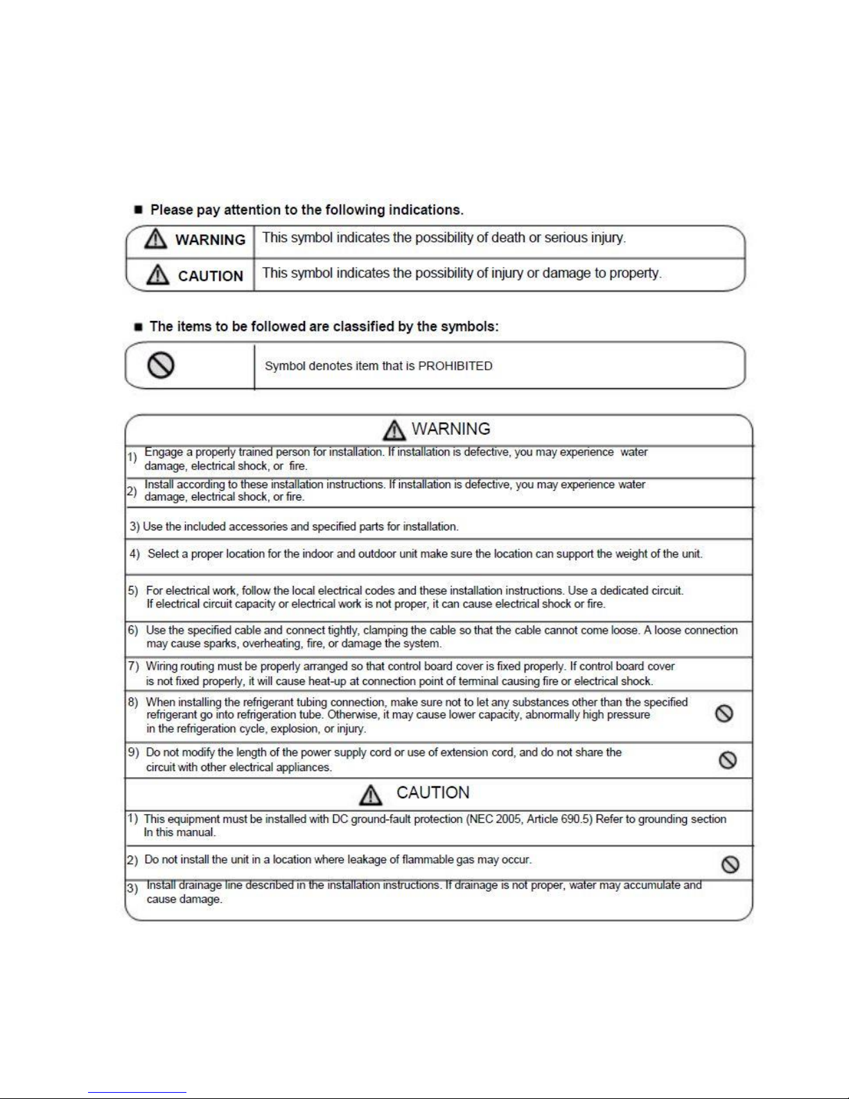
SAFETY PRECAUTIONS
Read the follow SAFETY PRECAUTIONS carefully before installation.
Installation must be performed in accordance with the requirement of NEC and CEC by authorized
personnel only.
Incorrect installation due to ignoring of the instruction will cause harm or damage.
© 2015 CLIMA-TEKNOLOGIES, LLC
4
Installation Instructions
Select an installation location which is rigid and strong enough to support or hold the unit, and select a
location for easy maintenance. Read completely, follow instructions step by step.
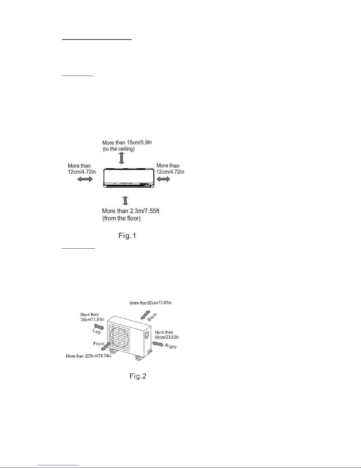
Indoor Unit Fig. 1
Do not expose the indoor unit to heat or steam.
Select a place where there are no obstacles in front of or around the unit.
Make sure that condensation drainage tube can be conveniently routed away.
Do not install near a doorway.
Ensure the spaces indicated by arrows from the wall, ceiling or other obstacles.
A place where noise prevention is taken into consideration. Min. 3 ft. from TV or
electronic instrument.
There should not be any direct sunlight on the indoor unit, sunlight may fade the color of the unit.
Outdoor unit Fig. 2
If an awning is built over the outdoor unit it must be done in a way that does not block air flow to the unit.
Keep the spaces indicated by arrows from wall or other obstacles.
Do not place animals and plants in the path of the air inlet or outlet.
Take the air conditioner weight into account and select a place where noise,
vibration, and hot air discharged will not be an issue.
Do not install in a location exposed to flammable gas.
Do not install high frequency machines such as a
welding machine near the air conditioner.
© 2015 CLIMA-TEKNOLOGIES, LLC
5
Rooftop installation:
If the outdoor unit is installed on a roof structure, be sure to level the unit.
Ensure the roof structure and anchoring method is adequate for the unit location. Consult local codes
regarding rooftop mounting.
Recommended Tools For Installation:
Level gauge Hex Wrench 5mm
Screwdriver Leak Detector
Electric Drill Vacuum pump
Hole Saw Bit Gauge manifold
Flaring Tool User’s manual
Torque Wrench Thermometer
Adjustable Wrench Multi-meter
Tape Measure Pipe Cutter
R410A Service Port Adaptor
Use a stud finder to locate wall studs. Directions B and C should be free of obstacles.
© 2015 CLIMA-TEKNOLOGIES, LLC
6
INSTALLATION INSTRUCTIONS
Indoor unit installation
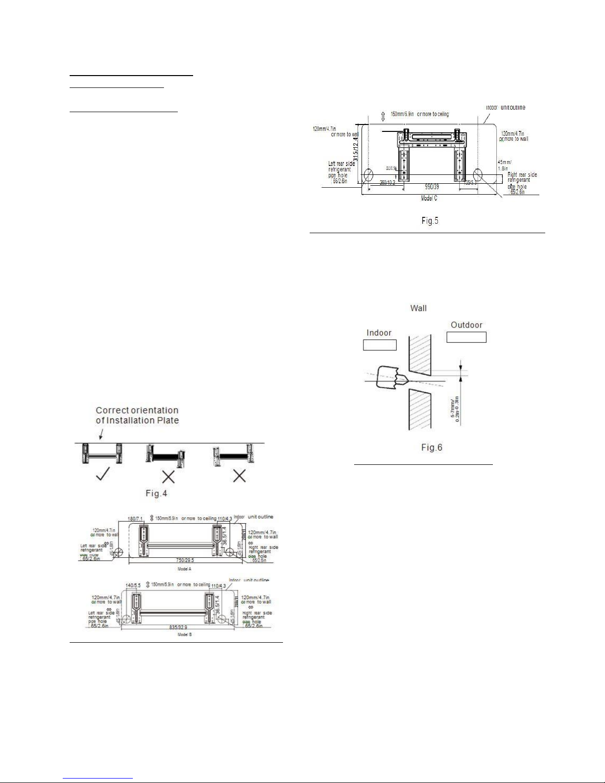
1. Fit the Installation Plate
1. Fit the installation plate horizontally on a structurally
sound part of the wall with spaces around the
installation plate.
2. If the wall is made of brick, concrete or the like use
anchor bolts.
3. Fit the installation plate on the wall with (8) type “A”
screws included.
Note:
F it the Installation Plate and drill
holes in the wall according to the
wall structure and corresponding
mounting points on the installation
plate. The installation plate is different
from the ACDC12 A model.
Dimensions are in “mm/in” unless stated otherwise.
4. Determine the hole positions according to the
diagram detailed in fig, 5. Drill (1) hole (65mm/2.6
in.) slanting slightly to the outdoor side. Fig. 6
5. Always use conduit when drilling through metal grid,
metal plate or the like.
7
© 2015 CLIMA-TEKNOLOGIES, LLC
INSTALLATION INSTRUCTIONS
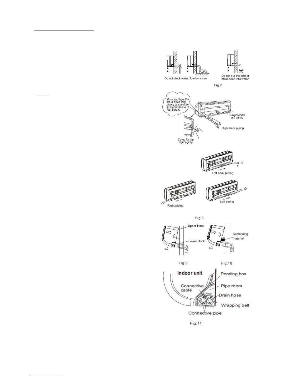
Connective Pipe and Drainage Installation
6. Run the drain hose sloping downward. Do not
install the drain hose as illustrated in Fig.7.
When connecting extension drain hose, insulate
the connecting part of extension drain hose with a
shield pipe, do not let the drain hose slack.
7. For the right-hand piping, remove the pipe cover
from the side panel. (Optional)
Install the piping as
NOTE: For 9K/12K model, there is only
one
side drainage structure design.
If choosing right side
another proper drain hose
is only one drain hose
connection
be done
leakage.
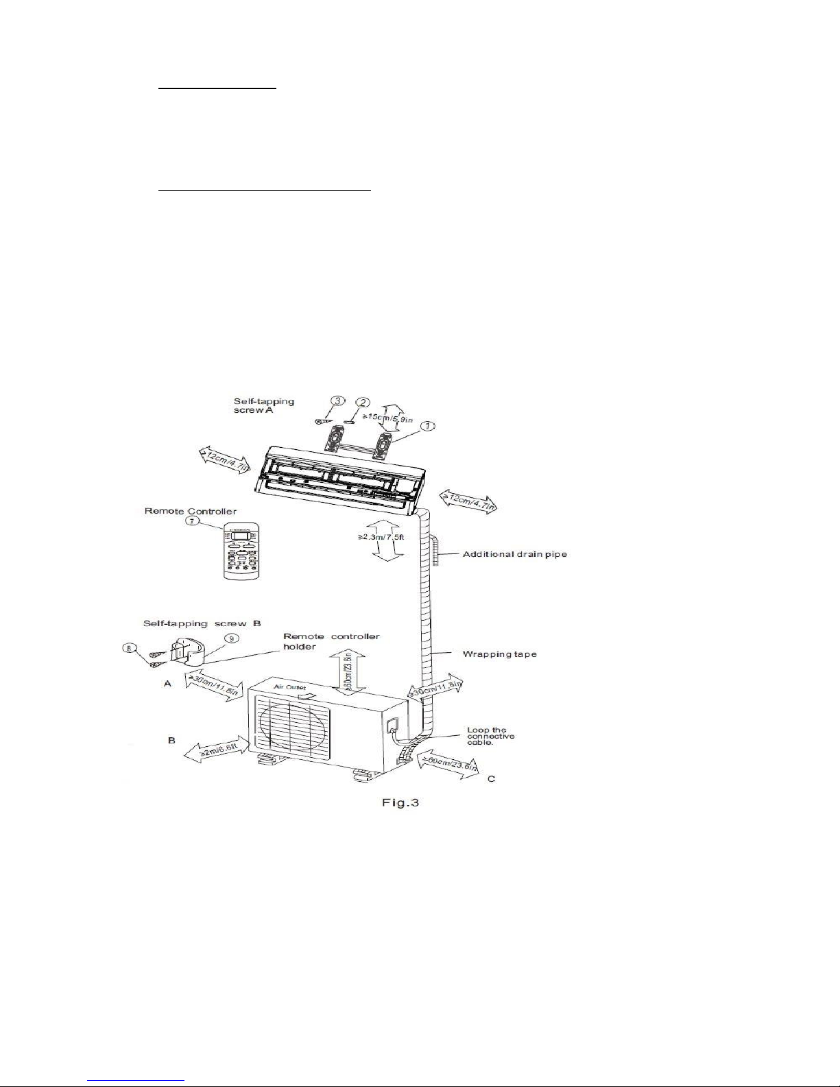
8. Bundle the tubing, connecting cable, and drain
hose with tape securely, evenly as shown in Figure
on the right.
9. The condensed water from the rear of the outdoor
unit is gathered in a ponding box and is piped out
of the room. Do not put anything else in the box.
10. Pass the piping through the hole in the
11. Put the upper claw at the back of the indoor unit
on the upper hook of the installation plate, move
the indoor unit side to side to see that it is
securely hooked (see Fig. 9 & 10).
12. Piping can be made easy by lifting the indoor unit
and placing a spacer between the indoor unit and
the wall.
13. Push the lower part of the indoor unit
wall, then move the indoor
side, up and down to
securely.
14. Bundle the tubing, connecting cable and drain
hose securely and evenly with tape as shown in
Fig. 12.
CAUTION
Connect the indoor unit first, then the outdoor
unit.
Do not allow the piping to let out from the back
of the indoor unit.
Be careful not to let the drain hose slack.
Be sure that the drain hose is located at the
lowest side of the bundle. Locating at the upper
side can cause drain pan to overflow inside the
unit.
of
by
qualified installer in case of water
shown.
the drain hose is supposed to
drainage
offered
check
connection,
is
needed as there
by factory. The
wall.
up
unit
from side to
if it is hooked
on the
Never intercross or intertwist the power wire
with any other wiring.
© 2015 CLIMA-TEKNOLOGIES, LLC
8
Outdoor Unit installation
Outdoor installation precaution
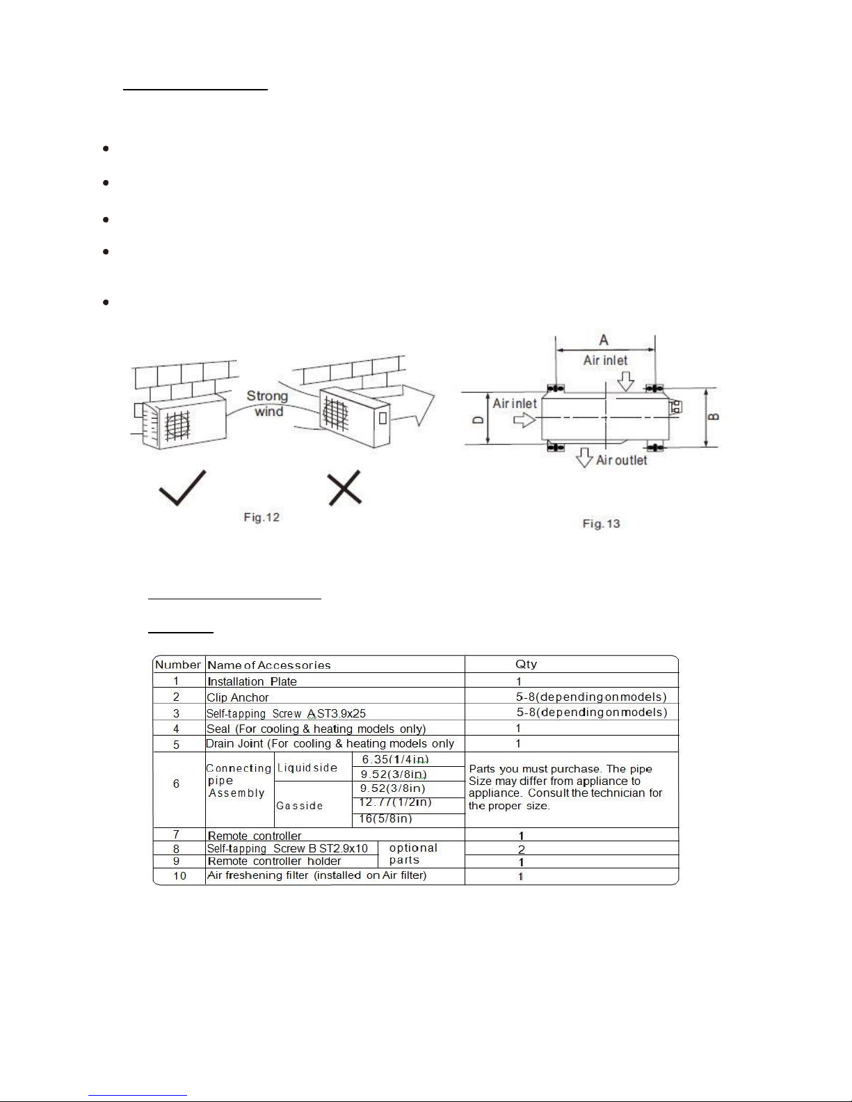
Install the outdoor unit on a rigid base to prevent increasing noise level and vibration. Determine the air outlet
direction where the discharged air is not blocked. In the case that the installation place is exposed to strong
wind such as a seaside, make sure the fan operating properly by putting the unit lengthwise along the wall or
using a dust or shield plates.
In windy areas, install the unit to prevent the admission of wind. If you need a wall mount installation, the
installation bracket should be installed according to the installation bracket diagram.
The installation wall should be solid brick, concrete or the same intensity construction, or actions to reinforce,
damping supporting should be taken. The connection between bracket and wall, bracket and the air
conditioner should be firm, stable and reliable.
Be sure there is no obstacle which can block radiating air.
INSTALLATION INSTRUCTIONS
Accessories
Note: Except the above parts provided, the other parts needed during installation
must be purchased separately. A condensate drain hose extension can be purchased separately from
Home Depot, 7/8 OD, 5/8 ID clear plastic tubing.
© 2015 CLIMA-TEKNOLOGIES, LLC
9
REFRIGERANT PIPE CONNECTION
Installation of Outdoor Unit
Anchor the outdoor unit with a bolt and
nut # 10 or # 8 tightly and horizontally
on a concrete pad or rigid mount.
4. Cut the cable 1.5m longer than the pipe
length.
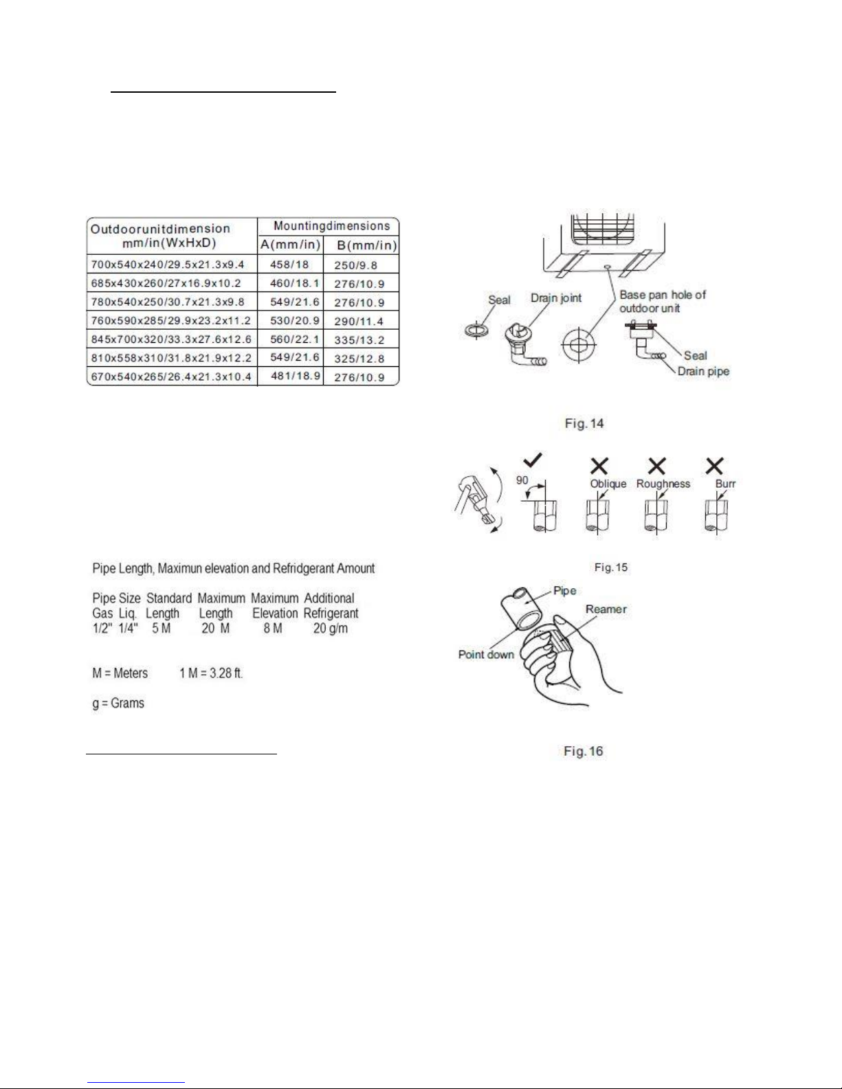
B: Burr removal
1. Completely remove all burrs from the cut
cross section of pipe/tube.
2. Put the end of the copper tube/pipe in a
downward direction as you remove burrs in
order to avoid dropping burrs into the tubing.
Drain joint installation
If a drain elbow is used, the unit should be
placed on a stand which is taller than 3cm.
Fit the seal into the drain elbow, then insert
the drain joint into the base pan hole of
outdoor unit, rotate 90 to securely
assemble them. Connect the drain joint
with an extension drain hose (Locally
purchased), to prevent water draining off
the outdoor unit during the heating mode.
Refrigerant pipe connection
1. Flaring work
The main cause for refrigerant leakage
is caused by a defect in the flaring work.
Perform correct flaring work
using the following procedure:
A: Cut the pipes and the cable.
1. Use the piping kit accessory or pipes
purchased locally.
2. Measure the distance between the indoor
and the outdoor unit.
3. Cut the pipes a little longer than the
measured distance.
C: Putting nut on
Remove flare nuts attached to indoor and
outdoor unit, then put them on pipe/tube
having completed burr removal.(not possible
to put them on after flaring work)
D: Flaring work
Firmly hold copper pipe in a die in the
dimension shown in the table below.
© 2015 CLIMA-TEKNOLOGIES, LLC
10
 Loading...