

Page 1

LCB 30 y LCB 50
Calibration Bath
ManU
al
LCB 30 & LCB 50
CALIBRATION MICRO BATH
MANUAL
Page 2

Leyro Instruments® doesn’t accept warranty and liability claims
neither upon this publication nor in case of improper treatment of the
described products.
The document may contain technical inaccuracies and typographical
errors. The content will be revised on a regular basis. These changes
will be implemented in later versions. The described products can be
improved and changed at any time without prior notice.
© Copyright Leyro Instruments ®
All rights reserved.
Page 3

INDEX
1. General Information
1.1. Symbology
2. SAFETY
2.1. Use as planned
2.2. Staff qualifications
2.3 Personal protective equipment
2.4 Specific Risks
2.5 Safety instructions for using calibration liquids
2.6 Explanation of symbols
3. Homologation data and certificates
4. Design and function
4.1. Description
4.2. Scope of delivery
4.3. Overview of the different models of the device
4.4 Description of the control elements
5. Transport, packaging and storage
5.1. Transport
5.2. Packaging
5.3 Storage
6. Commissioning service
6.1 Checking temperature sensors
6.2 Startup Procedure
6.3 On the Micro-bath
6.4 Displaying the reference temperature and the nominal temperature
6.5 Regulation of reference temperature to the maximum
6.6 Operating Position
6.7. Inner sleeves
6.8. Preparation of micro calibration bath
6.8.1 Properties of calibration liquids
6.8.2 Filling the micro calibration bath
6.8.3 Operating the magnetic stirrer
7.0 Micro calibration bath management
7.1. Operation in calibration mode in each operating mode
7.2. Calibration (calibration mode)
8.0 Cooling Micro-bath Calibration
9.0 Maintenance, cleaning and Re calibration
9.1 Maintenance
9.2 Cleaning
9.2.1 Cleaning the micro calibration bath
9.2.3 External cleaning
9.3 Re calibration
10.0 Failures
11.0 Dismantling, removal and waste disposal
11.1 Dismantling
11.2 Return
11.3 Waste disposal
12.0 LCB 30 and LCB 50 accessories
Page 4
1. General Information
• This instruction manual provides important information about the instrument operation. In order to work with this
instrument safely it is essential to comply with all safety and handling instructions provided
• Always comply with the regulations on accident prevention and safety rules in force at the place of use of the
instrument.
• The instruction manual is an integral part of the instrument and must be stored in the vicinity thereof so specialized
staff can refer to it at any time
• The qualified personnel must have read and understood the instruction manual before starting any work
• The manufacturer is discharged from any liability for damages caused by usage not according to the intended purpose
of use, non-observance of this manual, handling by insufficiently qualified personnel as well as unauthorized
modification of the instrument
• General conditions of sale included in the sales documentation apply.
• Technical modifications reserved
• Factory calibration and calibration by the Spanish association of calibration (ENAC / ISO 17025) are performed in
accordance with international standards
• For more information refer to:
-Web page: www.leyro.net
-Relevant technical sheet: LCB 30, LCB 50
-Technical service : +3491283502
info@leyro.net
1.1 Symbology
WARNING
DANGER
... Indicates an immediately dangerous situation which causes death or serious injury if not avoided
... It indicates a potentially dangerous situation which may cause death or serious injury if not avoided
... It indicates a potentially dangerous situation which may cause death or minor or medium injury or
material or environmental damage if not avoided
... Marks useful tips and recommendations as well as information for efficient and fault-free use
DANGER
... Indicates hazards caused by electric current. There is a risk of serious or deadly injuries if safety
instructions are not observed.
... It indicates a possibly dangerous situation which may cause burns due to hot surfaces or liquids if not
avoided
WATCH OUT
Information
WARNING
Page 5
2. SAFETY
WARNING
2.1 Use as planned
The micro calibration bath is a portable unit for technical service, industrial and laboratory tasks. Leyro Instruments’
micro temperature baths or micro calibration baths are provided for calibrating thermometers, switches / thermostats
thermos, pyrometers electrical resistance and thermocouples.
The product has been designed and built only for the purpose described here and should be used in accordance to it.
Meet the technical specifications of this manual. An inappropriate handling or use of the equipment is not in accordance
with the technical specifications requires the immediate service and verification by an authorized Leyro Instruments
technician.
Handle the electronic precision instrument with due diligence (protect against humidity, strong impacts magnetic fields,
static electricity, extreme temperatures; Do not introduce any objects into the openings instrument). Pins must be
protected against dirt.
If the instrument is moved from a cold to a warm environment, a malfunction due to condensation can occur. In this case
you have to wait until the temperature of the instrument suits the room temperature before putting it back into operation
No claim due to inappropriate handling is admitted.
2.2 Staff qualification
WARNING
Specialized staff
Because of their professional training, their knowledge, control and measurement technology, as well as their
experience and knowledge of regulations, standards and guidelines in the country of use, specialized staff is able to
perform the works described and recognize possible dangers by themselves.
Some specific usage conditions require additional knowledge. E.g, about aggressive environments.
2.3 Personal protective equipment
The personal protective equipment protects qualified personnel from hazards which may harm their health and safety
during work. The specialized personnel must wear a personal protective equipment during the different works on and
with the instrument..
Comply with the indications about personal protective equipment in the work area!
The owner must provide personal protective equipment.
... Before installation commissioning and operation make sure you have selected the appropriate micro
calibration bath respect to measuring range, version and specific measurement conditions.
Risk of serious injury and / or property damage if not avoided,
... The different chapters of this manual contain other important safety instructions.
Risk of injury due to insufficient qualification!
Improper handling can cause considerable personal and property damage.
The activities described in this manual should be performed only by qualified personnel with the
appropriate qualifications.
Wearing protective glasses!
These protect the eyes from projected parts and splashes.
Page 6
2.4 Specific Risks
WARNING
In the case of dangerous substances to be measured, e.g. oxygen, acetylene, flammable toxic substances, as well as
in refrigeration premises, compressors, etc., the relevant provisions must be observed in each case, plus all general
rules,
DANGER
Risk of death, by electric current. There is direct danger of death from touching live parts
Residual media in dismounted instruments can cause risks to people, the environment and installation. Take
appropriate precautions
Overheating protection
WARNING
WARNING
If a malfunction of micro calibration bath can cause personal injury or property damage, it is necessary to ensure the
subsequent installation of electromechanical protection devices
• The installation and assembly of electric products must only be performed by a qualified electrician
• Before replacing the fuse circuit breakers, cleaning and maintenance / conservation and in the case of
danger, disconnect the micro calibration bath network by removing the power cord from the electrical outlet
• For your safety and the micro calibration bath is equipped with a protection on independent temperature that
disconnects the power supply of heating in case of excessive temperature inside the housing. After cooling
must send the micro bath to control Leyro Instruments
• The micro calibration bath is designed as a product of measurement and regulation. You need to take further
protective measures if the micro calibration bath for applications not explicitly mentioned in this manual is
used.
• Do not use the micro calibration bath in atmospheres hazardous (flammable or explosive atmosphere)
Page 7
2.5 Safety instructions for using calibration liquids
Calibration liquid water
Only use distilled water, otherwise Tartar forms and micro bath deposit gets dirty.
Calibration liquid silicone oil
WARNING
Only use the silicone oil recommended in this manual
Read the safety data sheet before starting to work with silicone oil. The data sheet is available from the
manufacturer or distributor.
Ensure that the room is well ventilated when working with silicone oil because harmful substances may
escape.
Because the silicone oiling is hygroscopic, always close the micro bath with the transport cover after use.
The transportation cover is equipped with a safety valve. If the micro calibration state is closed in hot
condition, unacceptable pressures may occur, to avoid overpressure that can destroy the liquid bath, the
safety valve is activated with an accuracy of about 2.5 bar. Hot steam may escape.
Wearing safety glasses!
Make sure that the silicone oil does not get in touch with the eyes
WARNING
Risk of burns
Before transporting or touching the micro-bath it is necessary to ensure that it is to sufficiently cool because otherwise
there is a risk of burns
2.6 Explanation of Symbols
It is absolutely necessary to read the instruction manual before installation and
commissioning of the equipment
EC European Community
Instruments with this mark comply with applicable European directives.
Page 8

Homologation and certificates, LCB series
CE compliance
Low Voltage Directive
Low Voltage Directive
Certificate
Calibration
3.0 Homologation data and certificates
2004/108 CE, EN 61326 Emission (Group 1, Class B) and resistance to
interferences (industrial locations)
2006/95 / EC, EN 61010-1, safety regulation for electrical measuring, control,
regulation and laboratory instruments
3.1 calibration certificate according to DIN EN 10204
For more technical details see data sheet from Leyro Instruments and order documentation.
3.1 LCB LCB 30 and 50 Micro calibration bath
Temperature range
Accuracy
Uniformity
Screen Resolution
Heating time ²
Cooling time ²
Depth
Volume Approximately 0.7 liters Approximately 0.7 liters
LCB 30 LCB 50
Option: calibration certificate ISO 17025 ENAC
-35 ... 165 ºC / -31 ... 329 ºF (1) 30 ... 225 ºC / 86 ... 437 ºF
± 0.3 ºC / ± 0.5 ºF ± 0.3 ºC / ± 0.5 ºF
± 0.05 ºC / ± 0.09 ºF ± 0.05 ºC / ± 0.09 ºF
0.1ºC / 0.1 ºF 0.1ºC / 0.1 ºF
-20 to 120 ºC / - 4 to 248 ºF: 35 minutes 25 to 220 ºC / 77 to 428 ºF : 42 minutes
30 to -20 ºC / 86 to - 4 ºF: 30 minutes 220 to 100 ºC / 428 to 212 ºF: 35 minutes
190mm / 7.48 in 190mm / 7.48 in
Tank dimensions
Auxiliary power 88 A 264 VAC
Electricity consumption
Network connection cable
Box
Dimensions
Weight
(1) AT 52 ºC / 125.6 ºF below ambient temperature.
2) The reference thermometer with which the measurement is made has a diameter of 6mm / 0.24 in.
Tests performed at an ambient temperature of 20 ºC ± 3 ºC / 68 ºF ± 5.5 ºF.
ACCESSORIES LCB 30 LCB 50
Silicone oil AC 10
-30 ... 160 ºC / FP = 170ºC
-22 ... 320 ºF / FP = 338 ºF
Silicone oil AC 20
-20 ... 200 ºC / FP = 240 ºC
- 4 ... 392 ºF / FP = 464 ºF
60 x 190 mm / 2.36 x 7.48 in 60 x 190 mm / 2.36 x 7.48 in
45-65 HZ
310 W MAX 320 W MAX
AC 320 for Europe AC 320 for Europe
280 x 280 x 400mm (An x Al x P) 280 x 280 x 400mm (An x Al x P)
11.02 x 11.02 x 15.75 in (An x Al x P) 11.02 x 11.02 x 15.75 in (An x Al x P)
12.8 kg / 28.22 lb 11.4 kg / 25.13 lb
Recommended
Recommended
88 A 264 VAC
45-65 HZ
Not recommended
Not recommended
Silicone oil AC 50
30 ... 220 ºC / FP = 280 ºC
86 ... 428 ºF / FP = 536 ºF
Silicone oil AC 100
70 ... 288 ºC / FP = 315 ºC
158 ... 550.4 ºF / FP = 599 ºF
Not recommended Recommended
Not recommended Recommended
FP = Flashpoint
Page 9

4. Design and function
4.1
Description
The micro calibration bath is a portable unit for technical, industrial service task at the laboratory. Leyro Instruments’
micro calibration baths are provided for calibrating thermometers, switches / thermostats, electrical resistance
pyrometers and thermocouples. The operational safety of the equipment is only guaranteed when used as planned
(control of temperature sensors).
The limit values specified should not be exceeded under any circumstances (see Chapter 3 "Technical Data").
The corresponding equipment must be selected according to the application. The product is then properly connected
and tests must be conducted0 and monitor the proper maintenance of all components.
The product is manufactured in several versions. The version is indicated on the nameplate on the micro calibration
bath
4.2
The micro calibration baths are shipped in a special safety packaging. The packaging must be kept to send the micro
calibration bath safely to the manufacturer for repair or recalibration
Standard supply volume of the micro calibration bath model LCB
Compare by packing list if all parts have been delivered
WARNING
Use only the supplied power cable
Micro temperature baths
The micro calibration bath is comprised of sturdy steel painted grey and provided with a carrying handle.
The back contains a bore accessible from above for the introduction of mass.
The liquid bath includes heating and cooling components for determining the reference temperature.
The bath liquid has a thermal insulation.
The front of the envelope contains the entire electronic control module for adjusting the reference temperature and a
potentiometer.
For handling heating or cooling towers networks semiconductor (SSR) are used.
On the front panel is the controller, which is equipped with a 7-segment LED (2 rows and 4 digits to indicate the
reference and nominal temperature.
The micro calibration bath further comprises a turning knob to control the stirring speed
Supply volume
Micro calibration bath
Transport cover
Basket for sensor
Magnetic stirrer
Power connection cable
Calibration certificate
Instructions Manual
4.3
overview of the different models of the device
LCB 30 (hot and cold)
LCB 50 (heat)
LCB 30 (hot and cold)
Page 10

4.4
Micro temperature bath model LCB 30/50
Micro Calibration Bath LCB 30/50
4.1
Isometric views of micro calibration bath series LCB
Front and top model LCB 30/50
At the top of the calibration is the refill opening (60 mm x 110m / 2.36 x 4.33 in)
The controller with the display and control elements are located on the front of the micro bath.
Page 11

Block
Potentiometer for the
LIQUID stirrer
PID controller
Rear of the equipment
At the rear of the instrument is the nameplate with the most important information about the specific model.
In addition the serial number is shown, for example S / N 53070005, and the main voltage and the value of the fuses
Block
Model nameplate
Power Supply
Page 12

Bottom of the instrument
The air inlet opening should not be blocked any way.
4.4 Description of command elements
Front Controller pid
4
5
7
6
8
9
1
Fun 1
Power connection box with main switch
3
2
Page 13

Overview of the control elements of the regulator front
1) P key
2) 6 key
3) 5 key
4) U key
5) LED OUT 1
6) LED OUT 2
7) PV indicator
8) SV indicator
9) LED SET
• Access to the defined nominal temperature
• Access to menu items and parameters
• Confirmation of introduction
• Reduction of the adjustable values
• Selection of each menu item
• It goes back 1 level in the menu
• Increase of the adjustable values
• Selection of each menu item
• It goes back 1 level in the menu
• Recovery of saved nominal temperatures
Indicates the status of the output for temperature regulation
• If the LED OUT 1 illuminates micro calibration bath is heated
• If it does not illuminate the LED OUT 1 micro calibration bath is not
heated
a) Heating equipment
Indicates the status of the output for fan control
• If the LED lights OUT 2 the fan rotates faster
• If it does not illuminate the LED OUT 2 The fan rotates at a slower
speed
b) Heating and cooling equipment
Indicates the status of the output for temperature regulation
• If the LED lights OUT 1 micro calibration bath is cooled
• If the LED OUT 1 does not illuminate micro calibration bath is not cooled
• The current reference temperature is displayed
• Each one of the modes and parameters menu items are displayed
• Visualization of the nominal temperature
• Certain parameters are displayed in each of the modes and menu items
Flashing indicates access to each of the menu items and parameters
Page 14

5.0 Transport, packaging and storage
5.1 Transport
Check if the micro calibration bath shows any damage caused during transport.
Report evident damages immediately
5.2 Packaging
Do not remove the packaging until just before installation.
Keep the packaging as it is the ideal protection during transport (e.g., if the installation site changes or if the product is
shipped for possible repairs).
5.3 Storage
Permissible conditions at the place of storage
• Storage temperature: -10 ... 60 ºC / -10 ... 140 ºF
• Humidity: 30 ... 95% RH (non-condensing)
Avoid the following
• Direct sunlight or proximity to hot objects
• Mechanical vibration, mechanical shock (sudden standing)
• Soot, steam, dust and corrosive gases
• Potentially explosive environment, flammable atmospheres.
6.0 Commissioning, operation
6.1 Checking the temperature sensors
To check the temperature sensors, connect a measuring instrument distinct of the checking sensor. By comparing
the temperature indicated on the external measuring instrument with the reference temperature, you can check the
status of the checking sensor. Watch that the sensor requires little time to reach the temperature.
WARNING
Thermocouples with grounding cannot be calibrated because they are grounded, so measurements could lead to
erroneous results
6.2
Starting Procedure
If the calibrator is not used for a long period, it is possible that moisture penetrates in the heating towers due to the
materials used (magnesium oxide). After transportation or storage of micro-bath in humid environments, heating towers
must be preheated slowly. During the drying process it is assumed that the micro-bath has not yet reached the required
isolation voltage for the protection class.
6.3
Starting the Micro calibration bath
1) Create a connection to the electric network via the provided jack
2) Press the switch. The regulator is activated. At the top PV screen the word TEST appears. On
the lower display the version number is displayed, for example Rl 2.7
Page 15

After about 5 seconds activation has been completed and the calibration mode is automatically displayed.
Mounted heating and cooling towers regulate micro-bath’s temperature automatically modifying the room
temperature to match the adjusted nominal temperature on the regulator
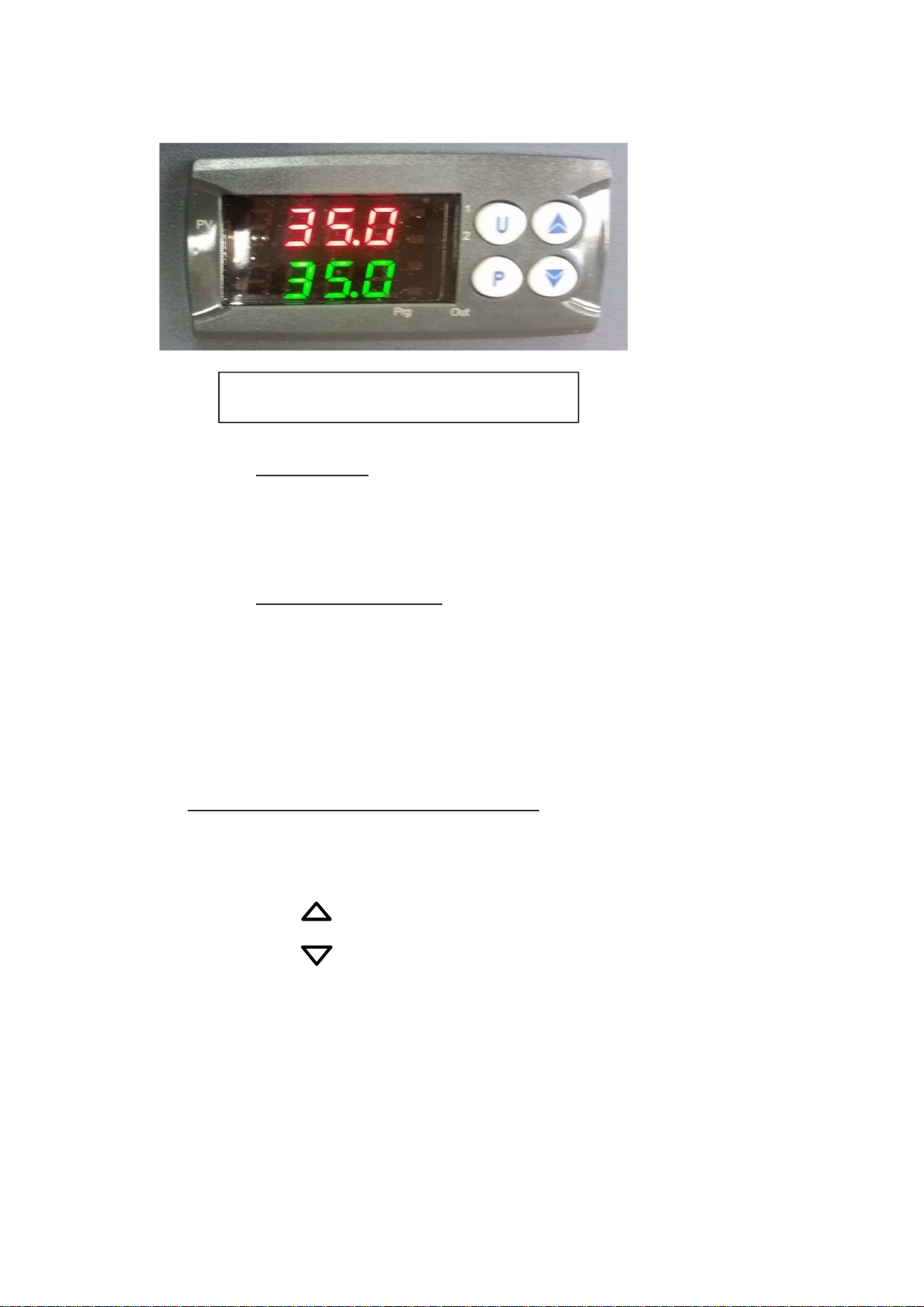
6.4 Viewing the reference temperature and the nominal temperature
Upper indicator
The 4 digt – seven segments red indicator displays the current temperature of the micro-bath
Lower indicator
On the 4 digit-7 segment green indicator the current nominal temperature of the micro-bath is displayed.
After reaching the nominal temperature, the issue of heat energy generated by the micro-bath continues through start
pulses in order to maintain the temperature level inside stable.
6.5 Regulation of reference temperature up to the maximum
The red LED OUT 1 indicates that the heating is on. During the heating phase a constant light indicates the input of heat
energy. A flashing LED means that the reference temperature (adjusted nominal temperature) will be reached soon and
thus the heat energy will only enter at short intervals.
To ensure proper temperature stability the cycle time of the regulator is adjusted to a low level and the regulation output
is activated with high frequency.
6.6 Operating position
The vertical service position of the micro calibration bath is optimal as this position guarantees the ideal distribution of
the temperature in the micro-bath
6.7 Inner sleeves
After use remove the inner sleeve with the aid of a tool for sleeves and then proceed to cleaning.
This prevents sleeves from adhering to the micro-bath
6.8 Preparation of micro calibration bath
To achieve maximum accuracy of a micro calibration bath, fill with an appropriate calibration liquid
6.8.1 Properties of calibration liquids
Due to the specific features of the different calibration liquids different calibration results are obtained. A compensation
of calibration liquids should be performed, even in factory by the manufacturer if necessary.
Recommended calibration liquids for the different temperature ranges:
Water as calibration liquid
• Use only distilled or demineralized water. Otherwise tartar is formed and the deposit of micro bath gets dirty.
Silicone oil as calibration liquid
• Only use the silicone oil recommended in this manual
• Ensure that the room is well ventilated when working with silicone oil because harmful substances may
escape
• Because the silicone oil is hygroscopic, always close the micro bath after use with the transport cover
Only use clean calibration liquids. Checking the temperature sensors and other temperature measuring means may
generate dirt in the fluid .This calibration can cause abrasions dirt on the floor of the tank caused by movement of the
rotary magnetic stirrer.
Page 16

Wearing protective glasses!
Ensure that the silicone oil does not come into contact with eyes
• Clean the trunk
• Clean sensors before performing the calibration
• Replace worn-out magnetic stirrer
• Replace the tainted and muddy calibration liquid
Mean
Silicone oil AC 10
- 30 ... 160 ºC 170 ºC
- 22 ... 320 ºF 338 ºF
Silicone oil AC 20
- 20 ... 200 ºC 240 ºC
- 4 ... 392 ºF 464 ºF
Calibration range
Inflammation point
Silicone oil AC 50
86 ... 428 ºF 536 ºF
Silicone oil AC 100
70 ... 288 ºC 315 ºC
158 ... 550.4 ºF 599 ºF
6.8.2 Filling the micro calibration bath
30 ... 220 ºC 280 ºC
1. Remove the cover transport LID first
2. Insert the testers in the basket for the sensor
3. Fill the trunk with calibration liquid
The following maximum filling heights are recommended by type:
Micro bath type Maximum filling height
LCB 30 150 mm / 5.91 in
LCB 50 150 mm / 5.91 in
The following aspects have to be considered regarding the maximum filling height:
• Measure from the bottom of the basket for the sensor
• Tank must not be full
• Leyro instruments standard filling mean
• Factory fill with the optimal height
The transportation cover is equipped with a safety valve. If the micro calibration bath is closed in a hot state,
inadmissible pressures may be produced. To avoid overpressure that can destroy the liquid bath, the safety
valve is activated with an accuracy of about 2.5 bar. Hot vapours may escape.
6.8.3 Operating the magnet stirrer
The maximum homogeneity is obtained by removing the calibration liquid using the magnetic stirrer.
Adjust the stirring speed. Turning the knob up speed is increased; down, the shaking motion slows down.
Page 17

front wheel controller with stirring speed
The magnetic stirrer is a wear part
Page 18

7.0 Micro calibration bath handling
For handling three modes are available
Calibration mode: In this normal operating state calibration of the tester can be performed
Nominal values mode: Enter the nominal temperatures in this mode
Main menu: Perform all settings like the nominal temperature given and the adjustment of the control parameters in this
mode
7.1 Operation in the calibration mode on each operating mode
"Micro-calibration bath" operating mode
Place the magnetic stirrer and basket for sensor
Fill the micro-calibration bath
Adjust the speed of the magnetic stirrer to achieve the highest homogeneity possible
Angle sensors, sensors with larger diameters or special designs cannot be calibrated in a micro-bath. So have a
circulation bath. The liquid circulates with the help of a magnetic stirrer seeking a very good distribution of temperature
in the bath. The liquids used are selected based on the desired calibration temperature.
"Micro-calibration bath" operating mode
Clean the tank if necessary
Set the magnetic stirrer speed to 0
The inner sleeve has several bores through which introduce temperature sensors to calibrate and the external reference
for a comparative calibration. The micro-bath is heated or cooled until reaching the desired calibration temperature.
When the temperature is stable, temperature probes to calibrate are compared to the reference thermometer
Page 19
Page 20
Page 21

Calibration of thermometers surface is very complex and not without ambiguities. The probe positioned on the surface of
the heat dissipating surface producing a cold spot on the surface to be measured. In the micro-bath temperature
calibration multifunctional calibration in a special cap surface it is generated to measure the temperature directly below
the surface with a standard thermometer. The thermometer pattern also indicates the cold spot by integrating the
temperature over the sensitive length of the reference thermometer and thus provides a true temperature calibration of
surface temperature sensors.
The cap is constructed to achieve the best result since the depth of drilling is set to sensitive length. If a separate
external reference is used for a comparative calibration, ensure that the sensitive length is known and it is located in
center of the surface and calibration
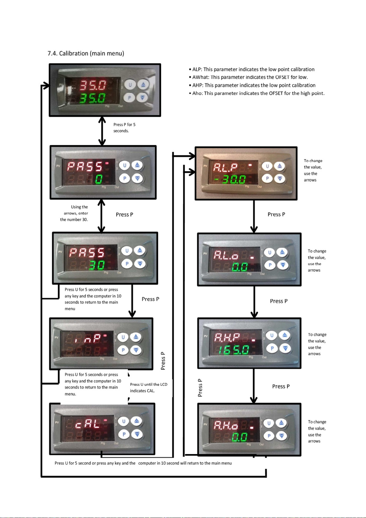
7.2 Calibration (Calibration Mode)
Once activated micro calibration bath, is in the calibration mode after initialization. In the upper indicator current
reference temperature is shown. the nominal temperature appears in the lower display.
The LED OUT 1 indicates the status of the output for heating control
If the OUT 1 LED lights up, the temperature rises
If the OUT LED is not lit, the heating is off
Calibration mode indicator HEAT
Page 22
The LED OUT 2 indicates the current reference. The nominal temperature appears in the lower display.
Calibration mode indicator FAN or COOL
The LED OUT 2 indicates the status of the output for fan control
Heating instrument
If the LED lights OUT 2 the fan rotates faster
If it does not illuminate the LED OUT 2 the fan rotates at a slower speed
Heating and cooling instrument
The LED OUT 2 indicates the status of the output for regulating the cooling system
If the LED OUT 2 lights up, the temperature decreases
If the LED OUT 2 lights no cooling is off
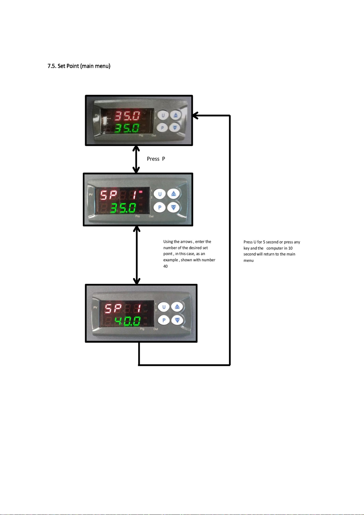
There are two methods to adjust the nominal temperature:
o You can set a temporary nominal temperature
o You can save fixed nominal temperatures in the main menu
Setting a temporary set temperature (nominal values mode)
To temporarily modify a nominal temperature stored in this state of operation follow these steps:
1 Briefly press the P key indicator in the upper memory currently active nominal values shown. the
corresponding nominal temperature appears in the lower display
2 Pressing the key nominal temperature is increased
Pressing the nominal temperature is reduced
3 Pressing the key P again the nominal value confirm new set
.
Page 23
8.0 Cooling micro-calibration bath
WARNING RISK OF BURNS
Before transporting or touching the micro-calibration bath it is necessary to ensure that it is sufficiently cooled
because otherwise there is a risk of burns on both the micro-bathand the proof. To bring the micro-calibration
bath from a high temperature to a low temperature as quickly as possible, the nominal temperature must be set
to a lower temperature than ambient temperature.
The fan integrated in the heating equipment rises slowly its rotation speed thus creating more cooling air.
The LED OUT 2 indicates the status of the output for fan control. If the LED OUT 2 fan rotates faster lights. If it
does not illuminate the LED OUT 2, the fan rotates at a slower speed.
The controller turns on the active cooling in the heating and cooling instruments. The LED OUT 2 indicates the
status of the output for active cooling. If the LED OUT 2 illuminates the active cooling is working. If it does not
illuminate the LED OUT 2 cooling is not active.
ATTENTION
After shutting down or removing the network connection built-in fan does not generate more cooling air.
However, a sufficient thermal decoupling is ensured between the micro-bath and the surrounds.
9.0 Maintenance, Cleaning and Recalibration
9.1 Maintenance
IT IS ADVISABLE TO TURN OFF THE CALIBRATION BATH WITH A SET POINT OF 25 ° C AND THAT IT
BE AT THE INDICATED TEMPERATURE, TO INCREASE THE LIFE OF THE EQUIPMENT.
The equipment described here requires no maintenance. All repairs must be performed only by the manufacturer.
Changing the fuse is excluded. Before changing this, disconnect the calibrator and micro-calibration bath by removing
the power cord from the electrical outlet.
9.2 Cleaning
ATTENTION
• Cool the micro-calibration bath
• Before cleaning micro calibration bath turn it off and disconnect it from the network
• Clean the product with a damp cloth
• Ensure that the electrical connections are not wet
• Once disassembled the product should be rinsed and cleaned before returning to protect people and the
environment against waste from measuring means
• Residual media in dismounted instruments can cause risks to people, the environment and the instrument..
See section 11.2 "Returning for more information about the return of the instrument
Take appropriate protective measures
Page 24

9.2.1 Cleaning micro-calibration bath
Remove all the silicone oil from the trunk. Remove the trunk sensor basket and clean it, the magnetic stirrer applying
water with lots of cleaning substances. Let all components dry. If distilled water is used remove the calibration liquid and
allow the sensor basket dry, the magnetic stirrer and the trunk.
9.2.2 External cleaning
Clean the outside of the micro-calibration bath with a damp cloth and some water or a non-aggressive cleaning product
without solvent.
9.3 Recalibration
Certificate ENAC ISO / 17025
The micro-calibration bath has been adjusted and tested before shipment using standard internationally recognized
quality measurement instruments.
According to ENAC ISO / 17025 micro-calibration bath must be checked at appropriate regular intervals depending on
use. It is recommended to Re calibrate the instrument by the manufacturer at regular intervals of about 12 months or
approximately every 500 hours of operation. All factories Recalibration includes also a comprehensive and free of
charge check of all system parameters as to the test specifications. Any deviation from the basic values is corrected.
The base of the Re calibration are the guidelines of the ISO / 17025 rules. The indications detailed in this document
must be observed and applied during Re calibration
Page 25
10.0 Failures
Failure
----
uuu
0000
EREP
The fan does not
work
The end
temperature is not
reached
Causes Measurements
The reference sensor stops or is defective
Measured temperature below the limit value of the
internal reference sensor (below the range-200ºC /
-328 ºF )
Measured temperature above the limit value of the
internal reference sensor (above the range + 850 ºC /
+ 1562 ºF)
Possible failure in the EEPROM memory of the
controller
The fan is defective or blocked.. It is possible that the
temperature switch has switched and thus cut the
power supply to the heating cartridges
The semiconductor relay is defective or the heating or
cooling tower have shorted or got old.
Send the instrument to the
manufacturer or service center
for repair
Press the P key
Send the instrument to the
manufacturer or service center
for repair
No indication
no function
ATTENTION
If the defaults cannot be corrected by the actions detailed above the instrument must be put out of service immediately
and prevent erroneous service start. In this case you must consult the manufacturer. If you wish to return the instrument
observe the indications in "Return" "
The regulator is defective
The network connection is not successful or fuse is
defective
Check power connection and
fuse
Page 26

11.0 Dismantling, return and disposal
WARNING
Residual media in dismounted instruments can cause risks to people, the environment and premises. Take appropriate
protective cautions.
11.1 Dismantling
1. Cool the instrument as described in "micro-bath cooling"
2. Turn off the micro-calibration bath and pull out the plug
3. Remove remains of calibration liquid from the micro-calibration bath. See "Cleaning the micro-bath"
WARNING
Risk of burns. Cool the product enough before dismounting. Danger due to hot media escaping during disassembly
11.2 Return
WARNING
It is essential to observe the following for shipping the instrument: All instrument sent to LEYRO INSTRUMENTS must
be free of hazardous substances (acids, alkalis, solutions, etc.).
Use the original packaging or a suitable packaging for returning the product..
To avoid damages;
1. Place the product together with the isolating material on the packaging. Isolate evenly all sides of the
transport packaging.
2. If possible, attach a bag with desiccant material.
3. Apply a marker indicating that it is the shipment of a highly sensitive measuring product
11.3 Disposal
Improper disposal can cause dangers to the environment. Eliminate the components of the products and packaging
materials in accordance with the regulations relating to waste treatment and disposal of the country of use.
Remove the silicone as described in the safety data sheet
Instruments with this label warn that they must not be disposed in a household waste. For removal they must be
returned to the manufacturer or deliver to the relevant communal institution.
Page 27

12.0 ACCESSORIES FOR LCB 30 AND 50
• Syringe for insertion or removal of fluid
• Transport metal LID
• Power cable 1.5 mm / 0.06 in with F type connector according to CEE7 / 4 standards
• Basket
• Magnetic stirrer and metal screw cap
Page 28

NOTES _____________________________________________
___________________________________________________
___________________________________________________
___________________________________________________
___________________________________________________
___________________________________________________
___________________________________________________
___________________________________________________
___________________________________________________
___________________________________________________
___________________________________________________
___________________________________________________
___________________________________________________
___________________________________________________
___________________________________________________
___________________________________________________
___________________________________________________
___________________________________________________
___________________________________________________
___________________________________________________
___________________________________________________
___________________________________________________
___________________________________________________
___________________________________________________
___________________________________________________
___________________________________________________
___________________________________________________
___________________________________________________
___________________________________________________
___________________________________________________
___________________________________________________
___________________________________________________
___________________________________________________
___________________________________________________
___________________________________________________
___________________________________________________
Page 29

HEAD OFFICE:
LEYRO INSTRUMENTS SL
Avda. Somosierra 24
28703 San Sebastián de los Reyes
Madrid, Spain
Tel: +34 912 835 502
info@leyro.net
www.leyroinstruments.com
Page 30

 Loading...