

Leyman TLS3510RL Hide-A-Way Installation Manual
Installation Manual
TLS3510RL Hide-A-Way®
Trailer Side Gate
LEYMAN MANUFACTURING CORPORATION
10335 Wayne Avenue
Cincinnati, OH 45242
1-866-LEYMAN-1 • 1-866-539-6261 • 513-891-6210
Fax 513-891-4901
www.leymanlift.com
sales@leymanlift.com
LML00084-04/20/17

2
TABLE OF CONTENTS
General Terminology
3
Gen. Spec. – Min. Mounting Space Req.
4
Before you install the Lift Gate
5
Pre-Installation of the Lift Gate
6
Side Door Mounting Information
7
Out Stop Mounting and Floor Thickness
8
Installation of the Lift Gate
9 - 10
Toggle Switch or Walk Around Installation
11 – 12
Charge Line
13
Grounding Recommendations
14
Wiring Diagrams – Circuit Breaker and
Additional Options
15 – 16
Installation Adjustments
17
Installation of Safety Decals
18
Final Installation Inspection
19
Recommended Oils and Lubrication
20
Operating Instructions
21
Operating the Optional Emergency Hand Pump
22
Maintenance Minder 2
23 - 25
Electric / Hydraulic diagram - Reference 26
Troubleshooting Guide
27
Notes
28
3
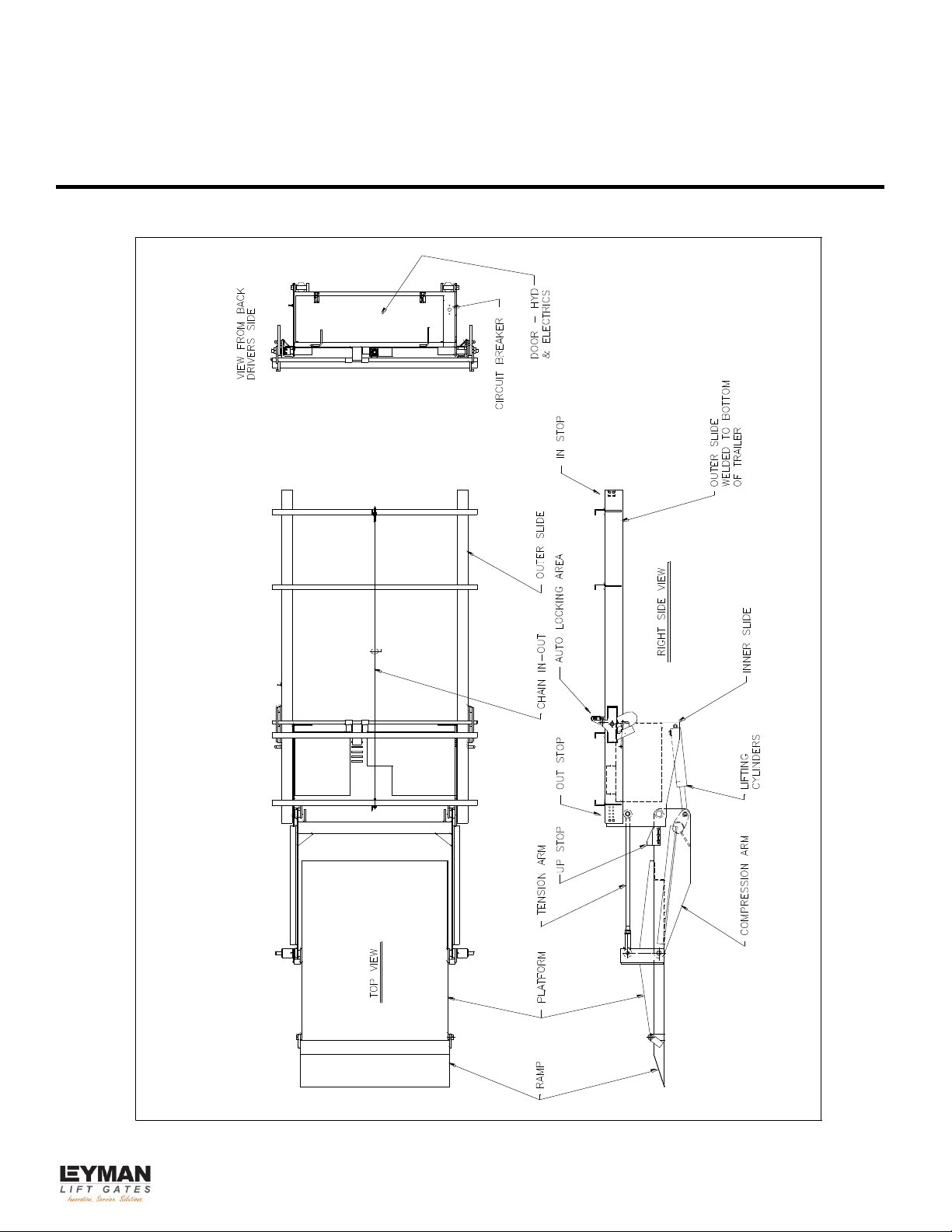
GENERAL TERMINOLOGY
4
GENERAL SPECIFICATIONS
CUSTOMER:
_____________________________________________________
MODEL:
TLS3510RL
CAPACITY:
3500 lbs.
TYPE:
Trailer Side Door Lift Gate
HYDRAULIC
PRESSURE:
2500PSI – Up Function
800PSI – In/Out Function
OPERATION:
Power up/Gravity down
Power in/out
SERIAL #:
_____________________________________________________
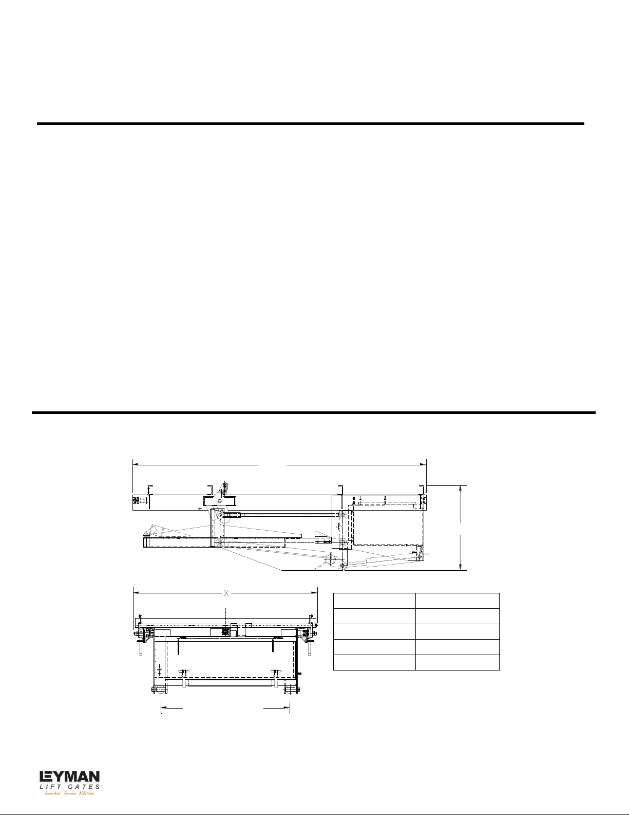
MINIMUM MOUNTING SPACE REQUIREMENTS
MINIMUM SPACE REQUIREMENTS NEEDED TO INSTALL THE TLS3510 SERIES GATE.
PLATFORM WIDTH
DIM. X = 90
DIM. X = 78
DIM. X = 66
DIM. X = 60
DIM. X WIDTH REQ.
27 1/2
95 3/4
PLATFORM WIDTH
72
48
60
42

5
BEFORE YOU INSTALL THE LIFT GATE
1. Check the lift gate for shipping damage.
2. Remove the shipping bands, etc. if the gate was shipped vertically, set the gate on the ground.
CAUTION – DO NOT INSERT FORKLIFT FORKS AT BOTTOM OF GATE NEAR DOOR.
Remove the shipping bands, etc. To set lift gate horizontal, chain or lash top cross tube
near chain anchor
3. Remove the box, open and read the installation manual. Check that all major parts have
arrived, such as the electrical box, optional mud flap (if ordered), etc.
4. Inspect the area under the trailer where the lift gate is to be mounted. Be sure the area is clear
of obstructions where the lift gate will be installed. Check the cross member material. If the
cross members are made of aluminum, the aluminum conversion kit (Option #133TLS) must
be ordered and used to mount the lift gate.
5. The use of a battery charger as the sole power source to operate the lift gate is unauthorized
and will prevent the lift gate from working properly. The lift gate must always be operated in
conjunction with at least one (1) 12 volt heavy duty lift gate battery. A minimum of 9.5 volts
must be maintained in order for the DOWN valve and 10.5 volts for the IN/OUT valves to
operate.
6. Read the following pages prior to beginning the installation.
A. Minimum mounting space requirements
B. Pre-installation of the lift gate.
C. Side door mounting information.
D. Installation of the lift gate.
E. Installation adjustments.
6
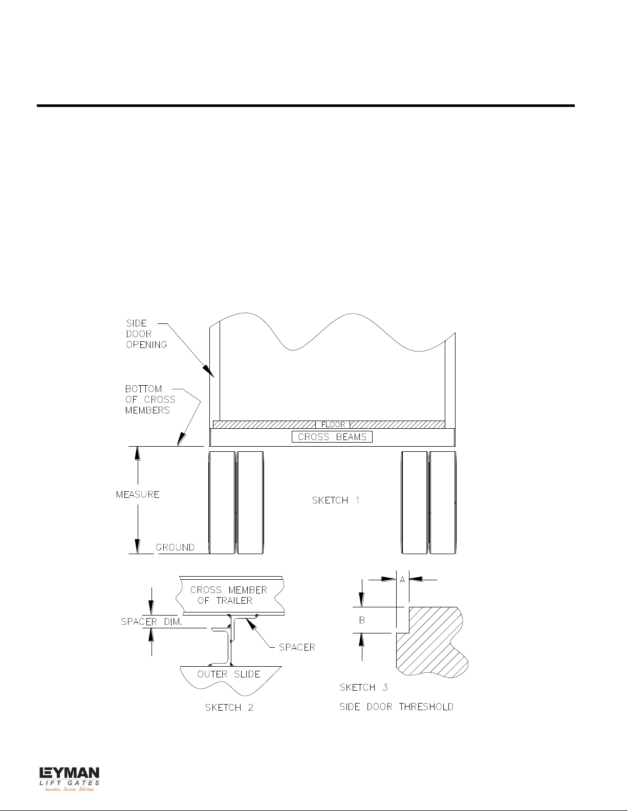
PRE-INSTALLATION OF THE LIFT GATE
1. Measure from the bottom of the cross members to the ground. If this measurement is less than
47 inches, spacers will not be required. This measurement must be 41.5 inches minimum in
order to yield 14 inches ground clearance for the gate. If the measurement is more than 47
inches, the amount in excess of 47 inches is the height of the spacer that must be added to the
four channels at the top of the Outer Slide. See Sketches 1 and 2.
2. Check the side door threshold. See Sketch 3. For the platform to properly enter the opening,
dimension “B” must be at least 1.5 times dimension “A”.
7
SIDE DOOR MOUNTING INFORMATION
Installation of Leyman side gates that are 42” wide are usually centered on the door opening
providing that the door opening is at least 42” wide.
For installation of Leyman side gates that are wider than the door opening, we recommend the gate
be offset to the rear of the trailer so when the door is open, it will not interfere with movement of the
platform.
Depending on the side door threshold, the platform may not fill the gap between the floor and the
platform. There are three options to correct this:
1. Notch the tip of the platform.
2. Add material to the tip of the platform (use a minimum thickness of 3/16” for proper
strength.)
3. Fabricate a flip plate to span the gap.
NOTE: End user option, material is not provided by Leyman.
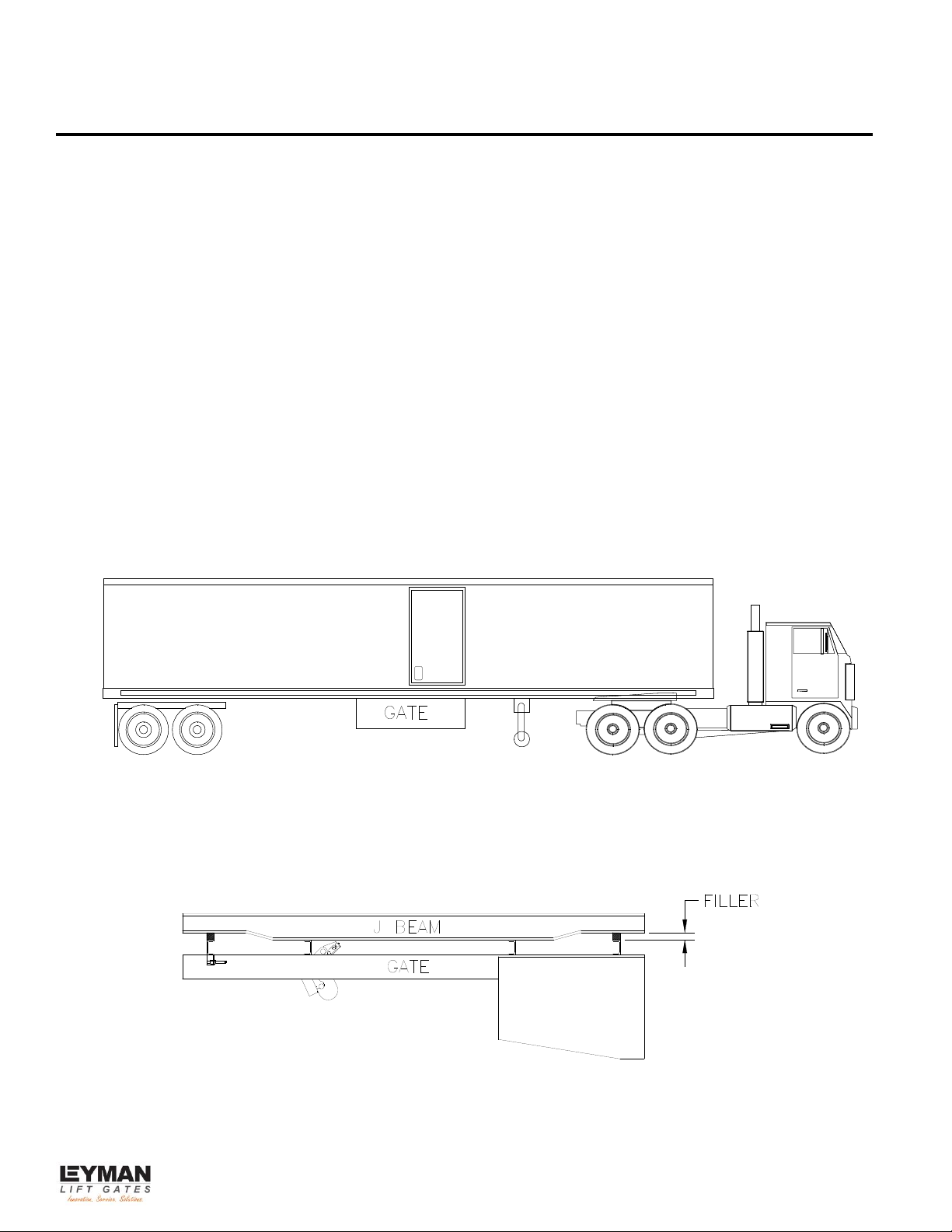
MOUNTING ON “J” CHANNELS
NOTE: FILLER MATERIAL NOT SUPPLIED BY LEYMAN
NOTE: Mounting to aluminum cross members will require the use of kit #133TLS.
8
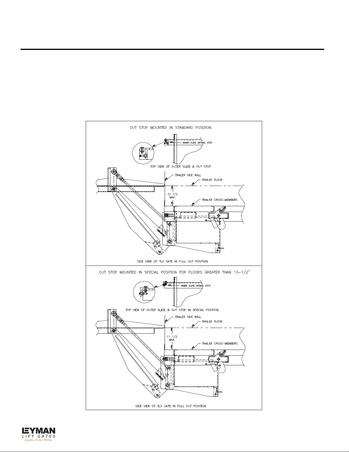
OUT STOP MOUNTING AND FLOOR THICKNESS
Determine the total floor thickness (vertical distance between the bottom of the cross-members
and the top of the floor inside the trailer). If that dimension is 10-1/2” or less, leave the Out Stops
mounted in the standard position. Mount Outer Slide rail face (fixed rail) flush with the rub rail.
If the total floor thickness dimension is larger than 10-1/2”, the Out Stops must be flipped around
as shown in the bottom half of the sketch below. In this case, the set screws in the Out Stops are
reversed as well. CAUTION! Out Stops must be adjusted so that Front Chain Anchor does not
strike Chain Cover Box.
9
INSTALLATION OF THE LIFT GATE
1. Mark the door opening on the vertical rub rail.
• For the 42” wide gate, mark the centerline of the door opening. For all others, mark the
leading edge of the door opening.
• NOTE: The centerline of the 42” wide gate is the center of the chain. Mark the centerline
on the channel. For all others mark the leading edge of the platform on the channel.
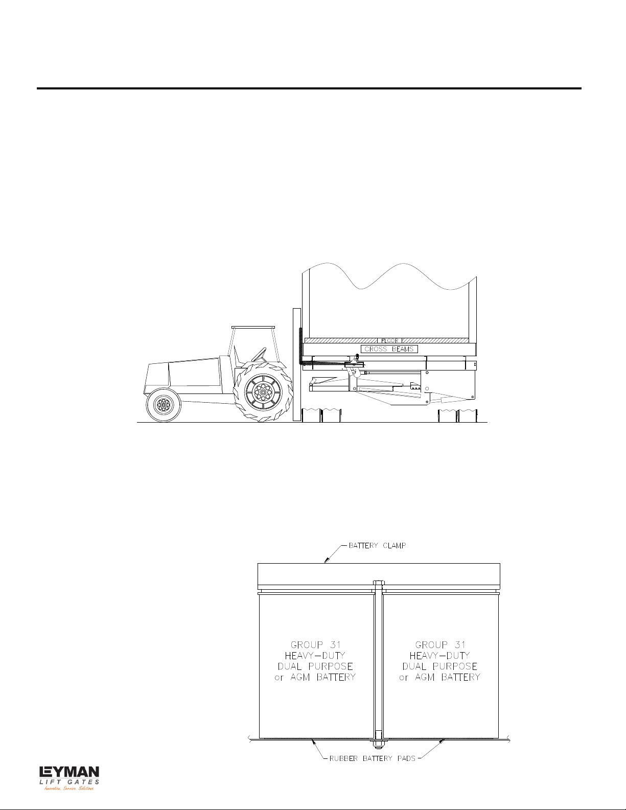
2. Raise the lift gate, use a lift truck. See the sketch below. Position the forks under the
spreaders (the four (4) three inch channels). Spread the forks as wide as possible.
CAUTION: Do not hit anything with the forks. Clamp the unit to the forks using two (2) “C”
clamps.
3. Pick the unit up, position it under the trailer. Line up the marks, which you put on the gate and
the rub rail. The front edge of the gate’s Outer Slide should be flush to the outside of the rub
rail. Weld the four (4) corners to the cross members.
4. Mount the electrical box. See the wiring drawings for location information. Drawings are
labeled “Toggle Switch Electrics or Walk-Around Electrics”. Finish wiring.
5. Install at least two (2) heavy-duty Dual Purpose or AGM batteries. Place rubber battery pads
under batteries. See sketch.
 Loading...