

Leybold vacuum TURBOTRONIK NT 10, TURBOTRONIK NT 12, TURBOTRONIK NT 13 Operating Instructions Manual

GA 05.212/10
TURBOTRONIK
NT 10
NT 12
NT 13
Elektronische
Frequenzwandler
Electronic frequency
converters
Kat.-Nr. / Cat. No.
859 00
859 01
859 04
859 05
859 06
859 07
Vakuum-Lösungen
ApplikationsUnterstützungen
Service
LEYBOLD VAKUUM
Gebrauchsanleitung
Operating Instructions

– 2 –
© LEYBOLD VAKUUM GMBH GA 05.212/10 - 09/00
TABLE OF CONTENTS
SAFETY-WARNING INFORMATION ................................. 4
1 DESCRIPTION .......................................................... 5
1.1 Function of design..................................................................5
1.1.1 TURBOTRONIK NT 10.....................................................6
1.1.2 TURBOTRONIK NT 12.....................................................6
1.1.3 TURBOTRONIK NT 13 with pressure trigger .................. 6
1.2 Technical data ........................................................................7
1.3 Scope of supply .....................................................................7
1.4 Accessories ........................................................................... 9
2 TURBOTRONIK NT10 CONNECTION AND
OPERATION........................................................... 10
2.1 Equipment configuration........................................................10
2.1.1 Supply voltage range ......................................................10
2.1.2 Relay assignment............................................................10
2.1.3 Resonance monitoring ....................................................10
2.2 Installing TURBOTRONIK ....................................................11
2.3 Electrical connection .............................................................11
2.3.1 Connecting the relay contacts ........................................11
2. 4 Operating modes / remote control .......................................12
1. Operation via the "ST A R T" and "STOP" buttons ..................12
2. Remote control via 2 external pushbutton............................12
3. Remote control via an external switch .................................13
4. Automatic start when the power is switched-on ...................13
2.5 Operator control ....................................................................13
3 TURBOTRONIK NT12 CONNECTION AND
OPERATION........................................................... 14
3.1 Equipment configuration........................................................14
3.1.1 Supply voltage range .........................................................14
3.1.2 Relay assignment...............................................................14
3.1.3 Resonance monitoring function.......................................14
3.2 Installing TURBOTRONIK .....................................................15
3.3 Electrical connection .............................................................15
3.3.1 Connecting the relay contacts ........................................15
3.4 Operating modes/remote control .........................................16
1. Remote control via 2 external pushbuttons..........................16
2. Remote control via an external switch .................................17
3. Automatic start when the power is switched-on ...................17
3.5 Operator control ....................................................................17
4 TURBOTRONIK NT13 CONNECTION AND
OPERATION........................................................... 18
4.1 Equipment configuration........................................................18
4.1.1 Supply voltage range ......................................................18
4.1.2 Relay assignment............................................................18
4.1.3 Resonance monitoring function.......................................18
4.2 Installing TURBOTRONIK .....................................................19

– 3 –
© LEYBOLD VAKUUM GMBH GA 05.212/10 - 09/00
TABLE OF CONTENTS
4.3 Electrical connection ............................................................. 19
4.3.1 Connecting the relay contacts (also refer to Fig. 8) ........19
4.3.2 Connecting the test sockets ...........................................20
4.4 Operating modes/remote control ..........................................21
4.5 Operator control ....................................................................21
5 SETTING THE EQUIPMENT CONFIGURATION ......... 22
5.1 Selecting the supply voltage range ....................................... 22
5.2 Withdrawing the PC boards...................................................23
5.2.1 NT10 ...............................................................................23
5.2.2 NT12 ...............................................................................23
5.2.3 NT13 ...............................................................................23
5.3 Locations of the plug-in and jumpers...................................24
5.4 Relay statuses ..................................................................... 25
5.5 Setting the configuration of relay K1 ....................................26
5.6 Setting the configuration of relay K2 ....................................26
5.7 Setting the resonance monitoring funct. ..............................27
5.8 Jumper field S2....................................................................27
5.9 Measuring the motor frequency ........................................... 28
5.10Connecting examples for remote control .............................29
EC DECLARATION OF MANUFACTURE ......................... 32
EC DECLARATION OF CONFORMITY ............................ 33
FACTORY CERTIFICATE ................................................ 34
FIGURES
Fig.1 TURBOTRONIK NT10 ............................................................6
Fig.2 TURBOTRONIK NT12 ............................................................6
Fig.3 TURBOTRONIK NT13 ............................................................6
Fig. 4 Dim.drawings of the Turbotronik NT10, NT12, NT13..............8
Fig. 5 Rear panel of the TURBOTRONIK NT10..............................12
Fig. 6 TURBOTRONIK NT 12, pin assignment...............................16
Fig. 7 TURBOTRONIK NT 13, pin assignment...............................20
Fig. 8 Voltage at the front panel test sockets.................................20
Fig. 9 Setting the supply voltage range..........................................22
Fig.10 Supply voltage selector switch TURBOTRONIK NT12 .......22
Fig. 11 Layout Platinen NT10 ........................................................24
Fig. 12 PC board layouts NT12 and NT13.....................................25
Fig. 13 - 17 Setting the configuration of relay K1 ...........................26
Fig. 18 - 22 Setting the configuration of relay K2 ......................26/27
Fig. 23 Setting the resonance monitoring function .........................27
Fig. 23 - 26 Jumper field S2 ......................................................27/28
Fig. 28 Diagram, measuring the motor frequency........................28
Fig. 29 Measuring the motor frequency.........................................28
Fig. 30 - 35 Connecting examples for remote control ..................29
Note (5/3) = refers to figure. The first digit refers to the number
of the figure, the second digit to the position.
– 4 –
© LEYBOLD VAKUUM GMBH GA 05.212/10 - 09/00
SAFETY-WARNING INFORMATION
Warning about the potential hazards of this equipment
This unit has voltages at hazarous potentials! Death, severe
bodily injury or significant material damage can occur if the
instructions in this Instruction Manual are not observed. Only
appropriately qualified personnel may work with this equipment.
This personnel must be knowledgeable about all of the warning
information and measures which are specified in this Instruction
Manual for the transport, installation, operator control and
troubleshooting of the equipment. The successful and safe
handling of this equipment requires that it is professionally
transported, installed and handled.
Caution
Disconnect the equipment from the supply and lock-out against
accidental reclosure before opening-up the equipment. When
connecting an external voltage of > 42 V to the terminals of the
unit, the VDE safety regulations must be observed!
Caution
This device contains devices which can be destroyed by
electrostatic discharge (ESD)!
Qualified personnel are personnel who are either suitably qualified
electricians or have had some form of electrical training in the
sense of EN 60204 Part 1, 3.55 and 3.30.
The electronic frequency converters NT10, NT12 and NT13 are
exclusively used for feeding turbo-molecular pumps
TURBOVAC 50 (Cat. No. 854 00, 854 01, 854 02 and 853 99)
TURBOVAC 50D (Cat. No. 856 60, 856 61, 856 62 and 856 63)
The connecting cables, specified under Section 1.4 must be used
to connect-up the above mentioned turbo-molecular pumps.
The EC manufacturer’s declaration becomes null and void
if the unit is changed without consulting us beforehand, or
if it is used for another purpose than it was originally
designed for!
It is not permissible to make changes or modifications on the
equipment for safety reasons. We retain the right to change the
mechanical design and revise the technical data.
Caution: Is specified for working- and operating procedures which
must be precisely maintained in order to avoid personnel being
subject to hazards.
Warning: Refers to working- and operating procedures which must
be precisely maintained in order to prevent the equipment being
damaged or destroyed.
Keep the Instruction Manual in a safe place for future use!
Qualified personnel
Proper use and
operation
Definition of caution
Definition of warning

– 5 –
© LEYBOLD VAKUUM GMBH GA 05.212/10 - 09/00
DESCRIPTION 1
Operating statuses
1.1 Function of design
The electronic TURBOTRONIC NT 10, NT 12 and NT 13
frequency converters are used to drive TURBOVAC 50 and 50 D.
They differ as follows:
n the housing
n the connectors,
n operator control possibilities
n scope of supply, and
n in the configuration in which they are supplied.
The electronic frequency converters convert the single-phase
supply voltage into a three-phase AC voltage to control the
TURBOVAC induction motor.
The frequency converters operate according to a specific cycle:
The motor is driven for approximately 1 second and the
monitoring measurements are executed in the following 0.1
seconds.
The following operating statuses are displayed using LEDs:
n supply voltage present
n run-up
n standard and
n fault Optionally
Various signals are available via 2 relay outputs.
After the start, the pump continuously accelerates with the
maximum current. This is identified by the yellow LED „ACCEL“
(acceleration) which is lit. The green „NORMAL“ LED is lit and
the „ACCEL“ LED goes dark when approximately 90% of the
rated speed is reached.
The speed is continuously monitored and controlled. When the
speed cannot be maintained, even at the maximum current, as a
result of external influences, e.g. excessive gas feed, the speed
decreases and the pump continues to operate.
When a rotational frequency of approximately 500 Hz is fallen
below, the „ACCEL“ LED lights-up on the frequency converter.
The TURBOTRONIK now attempts to accelerate the pump up to
its reference frequency.
The frequency converter outputs are no-load- and short-circuit
proof.
The electronic TURBOTRONIK frequency converters can be
connected to external open-loop control- and monitoring devices
with electrical isolation.
The cable connections between TURBOTRONIK - TURBOVAC
can be a maximum of 100 m.
Run-up and operation
Application and
function
Outputs
– 6 –
© LEYBOLD VAKUUM GMBH GA 05.212/10 - 09/00
DESCRIPTION 1
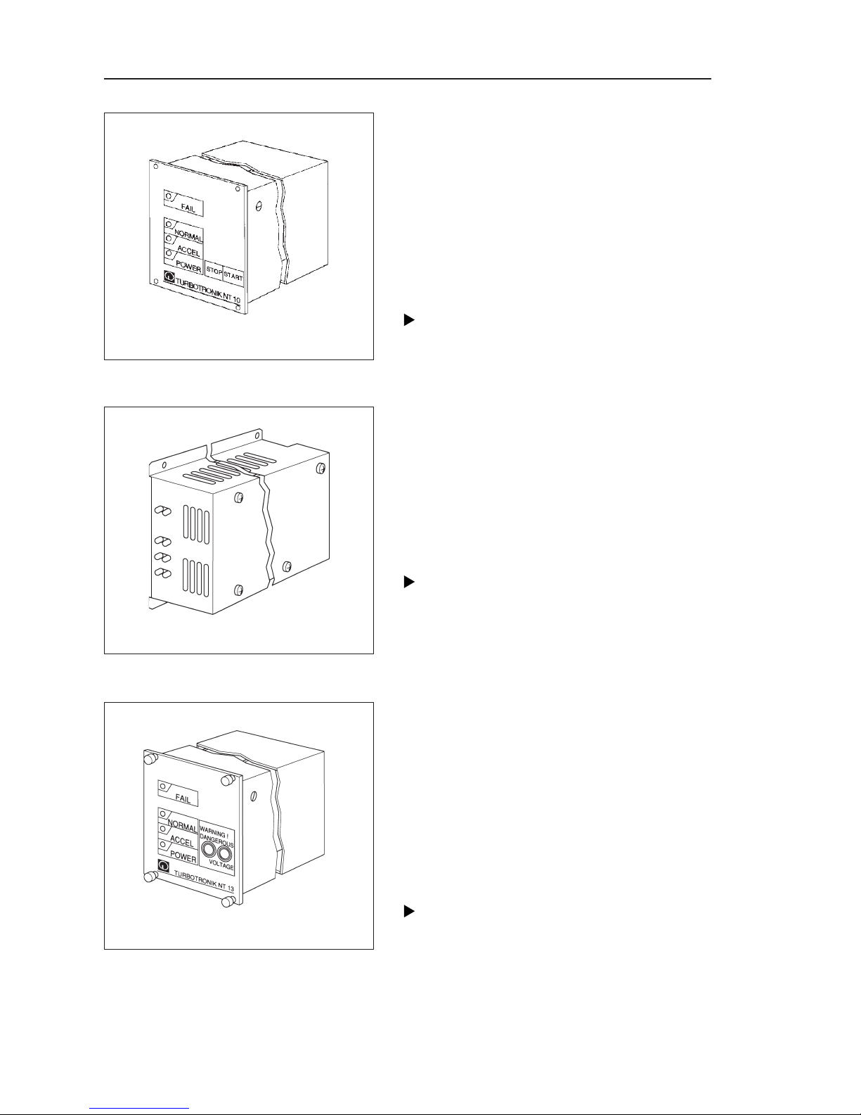
1.1.1 TURBOTRONIK NT 10
Desktop unit or
for mounting in a rack 1/4 19”, 3 HE
Front panel: Membrane keypad, 4 LEDs, “START”
and “STOP” keys
Housing: Extruded aluminum housing.
Rear panel: 10-pin Phönix connector for remote
monitoring and control, 5-pin connector to connect
the TURBOVAC, 3 m long power cable with
protective contact connector and
power switch
1.1.2 TURBOTRONIK NT 12
Chassis unit
Front panel: 4 LEDs.
Housing: Sheet-steel housing with screen plate
Rear panel: Plug connector strip in accordance
with DIN 41 612 with 15 contacts to connect the
TURBOVAC, the power and the remote control and
monitoring.
Note
A switch must be installed on the system side to
allow the equipment to be isolated from the supply!
1.1.3 TURBOTRONIK NT 13 with
pressure trigger
For mounting in rack ¼ 19“ rack, 3 HE
Front panel: Membrane-coated front panel with 4
LEDs and 2 test sockets
Housing: Extruded-aluminum housing.
Rear panel: Sheet steel, plug connector strip in
accordance with DIN 41 612 with 15 contacts to
connect the TURBOVAC, the power and the
remote control and monitoring.
Note
A switch must be installed on the system side to
permit the equipment to be isolated from the line
supply!
Fig.1 TURBOTRONIK NT10
Fig.2 TURBOTRONIK NT12
Fig.3 TURBOTRONIK NT13

– 7 –
© LEYBOLD VAKUUM GMBH GA 05.212/10 - 09/00
DESCRIPTION 1
1.2 Technical data
Supply voltage ranges..............................100-140 V AC,-10%/+16%
Can be switched-over to .................................. 200-240 V AC, ±10%
Supply frequency ................................................................ 50/60 Hz
Line fuse (F1 internal) ....................................................T 1A / 250 V
Rated speed of the TURBOVAC................... 72,000 RPM = 1200 Hz
Briefly when accelerating.................................... up to 64 VA (45 W)
Continuously in operation (rated speed) ...................... 35 VA (18 W)
Idle operation (no-load) .................................................... 6 VA (3 W)
Voltage ............................................................................... 3 x 150 V
Supply frequency ................................................................. 1200 Hz
Frequency range of the output voltage.......................... 220-1250 Hz
in operation ...................................................................... 0°C - 40°C
storage ...................................................................... -40°C to +85°C
Switching voltage ...........................................£ 250 V AC, £ 30 V DC
Switching current ................................................ £ 6 A AC, £ 5 V DC
Switching power for DC.........................................................£ 150 W
Switching power for AC......................................................£ 1500 V A
The units have degree of protection IP20 in accordance with
EN 60 529. An increased degree of protection, e.g. IP54 can only be
realized by mounting the units in other housings.
TURBOTRONIK NT 10.............................................................1.5 kg
TURBOTRONIK NT 12.............................................................1.5 kg
TURBOTRONIK NT 13.............................................................1.5 kg
TURBOTRONIK NT 10................................................. 1/4 19”, 3 HE
TURBOTRONIK NT 13................................................. 1/4 19”, 3 HE
1.3 Scope of supply
The connecting cable to the TURBOVAC is not included in the
scope of supply!
1.3.1 TURBOTRONIK NT 10
TURBOTRONIK NT 10, miniature fuses, mating connector for the
Phönix connector (control terminal strip X10), attachable feet for
desktop operation, 4 adhesive feet, four M 3x8 screws, the power
cable is permanently attached.
1.3.2 TURBOTRONIK NT 12
TURBOTRONIK NT 12, miniature fuse.
1.3.3 TURBOTRONIK NT 13
TURBOTRONIK NT 13, miniature fuses, 4 screws for rack
installation.
Power consumption
Outputs
Ambient temperature
Max. load capability of
the relay contacts
Weigt
Dimensions and
housing dimensions
(refer to Fig. 4)
Degree of protection
Supply
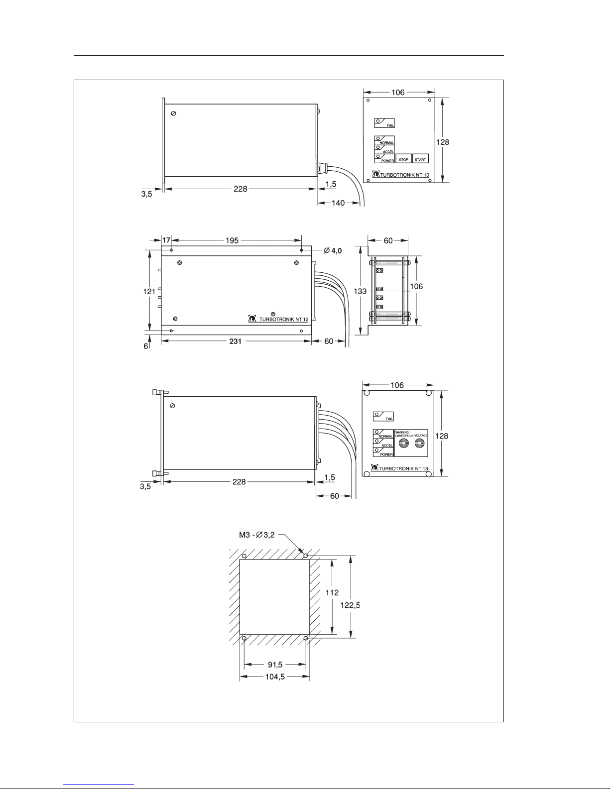
– 8 –
© LEYBOLD VAKUUM GMBH GA 05.212/10 - 09/00
TURBOTRONIK NT10
TURBOTRONIK NT12
TURBOTRONIK NT13
DESCRIPTION 1
Panel cut-out for
TURBOTRONIK NT10
and N13
Fig. 4 Dimension drawings of the TURBOTRONIK NT10, NT12, NT13

– 9 –
© LEYBOLD VAKUUM GMBH GA 05.212/10 - 09/00
DESCRIPTION 1
1.4 Accessories
Ordering information
Cat.-N0.
TURBOTRONIK NT 10
200 V - 240 V..................................................................... 859 00
100 V - 120 V..................................................................... 859 01
TURBOTRONIK NT 12
200 V - 240 V..................................................................... 859 04
100 V - 120 V..................................................................... 859 05
TURBOTRONIK NT 13
200 V - 240 V..................................................................... 859 06
100 V - 120 V..................................................................... 859 07
Connecting cable from the TURBOVAC to
TURBOTRONIK NT10
1 m long.......................................................................20011609
3 m long.............................................................................12108
5 m long.............................................................................12109
15 m long.............................................................................11990
TURBOTRONIK NT12
3 m long............................................................................857 54
TURBOTRONIK NT13
1 m long............................................................................857 56
A mating connector for the plug connector strip X11 including 15
contact pins are supplied with the connecting cable (only NT12,
NT13).
Accessories to mount NT 12 in a rack on request.
Electronic frequency
converter
Connecting cable
– 10 –
© LEYBOLD VAKUUM GMBH GA 05.212/10 - 09/00
2.1 Equipment configuration
2.1.1 Supply voltage range
TURBOTRONIK NT10 can be operated with two supply voltages;
between 200-240 V or between 100-120 V .
It is set in the factory for a specific supply voltage range which can
be identified by the Order No., refer to the Catalog No. under Section 1.4.
Caution
TURBOTRONIK will be damaged if it is connected to the wrong
line supply voltage.
Refer to Section 5.1 when changing-over the supply voltage range.
2.1.2 Relay assignment
TURBOTRONIK NT10 has 2 relays; the “NORMAL” (K1) and
“FAIL”/ fault (K2) signals are available at its outputs.
Relay K1 is available as changeover contact. The relay function
of K2 can be changed using a jumper. Further, relay K2 can be
changed over from an NO contact to an NC contact.
Relay K2 can be used to control the “pre-vacuum pump”. In this
case, it is active after the start, and inactive after the
TURBOVAC has been brought to a standstill, also refer to
Section 5.
2.1.3 Resonance monitoring
TURBOTRONIK NT 10 has a resonance monitoring function for
the TURBOVAC 50D. The resonance monitoring function shuts
down the drive and displays a fault if the pump remains in the
speed range between 45,000 and 55,000 RPM for longer than
approximately 1 minute. When shipped, the resonance monitoring
function is active, and can be disabled when operating the
TURBOVAC 50; also refer to Section 5.6.
Caution
If TURBOVAC 50D is used without the resonance monitoring
function, this can lead to bearing damage.
The equipment may only be connected-up by a suitably
trained electrician or under his supervision in accordance
with the valid IEC (international), EN (European) and/or domestic guidelines.
Caution
The TURBOTRONIK NT10 has parts and components at hazardous voltage levels. Before carrying out any work with the equip-
ment open, it must be isolated from the line supply and lockedout against accidental re-closure.
TURBOTRONIK NT10 CONNECTION AND OPERATION 2
Status when shipped
K2: Controlling the
prevacuum pump
Relaisbelegung umstellen
Tip
We recommend that if you
change the relay assignment
or if the resonance monitoring
is disabled, then this
should either be noted on
the equipment itself, or
documented in the associated
Instruction Manual.

– 11 –
© LEYBOLD VAKUUM GMBH GA 05.212/10 - 09/00
2.2 Installing TURBOTRONIK
TURBOTRONIK NT 10 is supplied in a housing as desktop unit.
When required, feet can be attached to the lower side. The feet
can be attached by inserting them into the lowest groove of the
corner strip from the back and pushing them towards the front
until they lock-in. Attach the four adhesive feet to the lower side
of the equipment feet and in the rear area of the unit.
TURBOLINK NT 10 can be installed in a rack. Ensure that it is
ad-equately ventilated. In operation, it is not permissible that the
ambient temperature exceeds 40°C.
If the rear panel of the TURBOTRONIK is no longer accessible
after it has been installed, switch-on the power switch (5/2)
beforehand.
Four holes in the front panel are used to install it in 19” racks.
2.3 Electrical connection
Insert the connecting cable to the TURBOVAC at the socket (5/4)
and at the TURBOVAC motor. The connector is secured using the
screw provided.
Note
It is impossible to incorrectly insert the pump connector as a
result of the different pins. When correctly assembled, this
plug connection has degree of protection IP65.
If you assembly your own connecting cable, observe that it can
be a maximum of 100 m long. Only use double-screened cables
with the appropriate insulation. If you require any further
information, please inquire.
Caution
High discharge currents! If the connecting cable between the
TURBOVAC and TURBOTRONIK is longer than 10 m, protective
ground must be connected to both units.
Connect the grounding cable (5/3) to the central grounding rail.
Connect the supply using the power cable (5/1).
2.3.1 Connecting the relay contacts
The “NORMAL” and “ACCEL” (acceleration) operating statuses
can be interrogated at pins 5,6,7.
Pins 6-7 closed: “NORMAL”
Pins 5-6 closed: “ACCEL”, standstill or fault
When a fault occurs, pins 9 and 10 are jumpered (NO contact).
The relays can be assigned differently, also refer to Section
2.3.2 and Chapter 5.
The supply voltage or functional low voltage can be connected
to the relay contacts. Observe the appropriate safety
regulations.
TURBOTRONIK NT10 CONNECTION AND OPERATION 2
Protective conductor
connection
Operating as desktop
unit
Rack insatllation
 Loading...