

Leybold vacuum TRIVAC S 4 B, TRIVAC B Series, TRIVAC D 4 B, TRIVAC D 8 B, TRIVAC S 8 B Operating Instructions Manual
TRIVAC®B
Rotary Vane Vacuum Pump
S/D 4 / 8 B
Cat. No.
102 45/46/55/56
103 01/02/03/04/05/06/07
103 11/12/13/14/15/16/17
112 45/46/55/56
113 01/02/03/04/05/06/07/08
113 11/12/13/14/15/16/17/18
Operating Instructions
Vacuum Pumps Instrumentation Fittings and Valves LEYBOLD VACUUM
GA 01.201/8.02

Contents
2
Contents
Page
1 Description . . . . . . . . . . . . . . . . . . . . . . . . . . 3
1.1 Function . . . . . . . . . . . . . . . . . . . . . . . . . . . . . 3
1.2 Supplied equipment . . . . . . . . . . . . . . . . . . . . . 5
1.3 Accessories . . . . . . . . . . . . . . . . . . . . . . . . . . . 6
1.4 Spare parts . . . . . . . . . . . . . . . . . . . . . . . . . . . 6
1.5 Transportation . . . . . . . . . . . . . . . . . . . . . . . . . 6
1.6 Technical data . . . . . . . . . . . . . . . . . . . . . . . . . 7
2 Operation . . . . . . . . . . . . . . . . . . . . . . . . . . . . 9
2.1 Installation . . . . . . . . . . . . . . . . . . . . . . . . . . . . 9
2.2 Connection to the system . . . . . . . . . . . . . . . . 9
2.3 Electrical connection . . . . . . . . . . . . . . . . . . . 10
2.3.1 Pump with single-phase AC motor . . . . . . . . . 10
2.3.2 Pump with three-phase AC motor . . . . . . . . . 10
2.4 Start-up . . . . . . . . . . . . . . . . . . . . . . . . . . . . . 11
2.4.1 Areas of application . . . . . . . . . . . . . . . . . . . . 11
2.5 Operation . . . . . . . . . . . . . . . . . . . . . . . . . . . 12
2.5.1 Pumping of non-condensable gases . . . . . . . 12
2.5.2 Pumping of condensable gases and vapours . 12
2.6 Switching off/shutdown . . . . . . . . . . . . . . . . . 12
2.6.1 Shutdown through monitoring components . . . 13
2.6.2 Failure of the control system or the
mains power . . . . . . . . . . . . . . . . . . . . . . . . 13
3 Maintenance . . . . . . . . . . . . . . . . . . . . . . . . 13
3.1 Checking the oil level . . . . . . . . . . . . . . . . . . . 14
3.1.1 Checking the condition of N 62 or HE-200 Oil 14
3.2 Oil change . . . . . . . . . . . . . . . . . . . . . . . . . . . 14
3.3 Cleaning the dirt trap . . . . . . . . . . . . . . . . . . . 15
3.4 Removing and fitting the internal demister . . . 15
3.5 Disassembly and reassembly of the
electric motor . . . . . . . . . . . . . . . . . . . . . . . 16
3.6 Replacing the outer shaft seal . . . . . . . . . . . . 17
3.7 Removing and remounting the pump module . 18
3.7.1 Removing the pump module . . . . . . . . . . . . . 18
3.7.2 Remounting the pump module . . . . . . . . . . . . 19
3.8 Leybold service . . . . . . . . . . . . . . . . . . . . . . . 20
3.8.1 Waste disposal of used pump materials . . . . . 20
3.9 Storing the pump . . . . . . . . . . . . . . . . . . . . . . 20
3.10 Troubleshooting . . . . . . . . . . . . . . . . . . . . . . . 21
3.11 Maintenance plan . . . . . . . . . . . . . . . . . . . . . 22
EEC Declaration of Conformity . . . . . . . . . . 24
Figures
The references to figures, e.g. (1/2) consist of the Fig.
No.and the Item No. in that order.
Indicates procedures that must be strictly
observed to prevent hazards to persons.
Indicates procedures that must strictly be
observed to prevent damage to, or
destruction of the equipment.
Leybold Service
If a pump is returned to Leybold, indicate whether the
pump is free of substances damaging to health or
whether it is contaminated.
If it is contaminated also indicate the nature of the
hazard. Leybold must return any pumps without a
“Declaration of Contamination” to the sender’s address.
Disposal of waste oil
Under the amended law relating to waste disposal dated
November 1, 1986 (valid in the Federal Republic of
Germany) the disposal of used oil is subject to new
provisions. According to legislation relating to waste
disposal the so-called principle of causality is applied.
Hence, anyone in possession of used oil is responsible
for its proper disposal.
Used oils coming from vacuum pumps must not be
mixed with other substances.
Used oils from vacuum pumps (LH-oils on the basis of
mineral oils) having been affected by normal
contamination due to oxygen from the ambient air,
increases in temperature and mechanical wear, must be
disposed of as used oil in accordance with the
regulations. Used oils from vacuum pumps that have
been contaminated by other substances must be
labelled, stored and disposed of as special waste with
reference to the kind of contamination.
When disposing of used oil please observe the safety
regulations that are valid in your country.
In many countries proof of were the oil has finally been
left is required by Law and often shipping of such
contaminated waste requires permission by the
authorities. Waste disposal information is available
through:
Bundesamt für Gewerbliche Wir tschaft (BAW)
Frankfurter Str.29-31
D-65760 Eschborn/Taunus
Phone: +49 (0)6196 4041 – Telex: 415603/04
Warning
Caution
123
Description
3
1 Description
TRIVAC-B pumps are oil-sealed rotary vane pumps.The
TRIVAC S 4 B and S 8 B are single-stage pumps, and
the TRIVAC D 4 B and D 8 B are dual-stage pumps.The
number in the type designation (4 or 8) indicates the
pumping speed in m3x h-1.
TRIVAC-B pumps can pump gases and vapours and
evacuate vessels or vacuum systems in the fine vacuum
range. Those of standard design are not suitable for
pumping greater than atmospheric concentrations of
oxygen, hazardous gases, or extremely aggressive or
corrosive media.
The drive motor of the TRIVAC-B is directly flanged to
the pump at the coupling housing. The pump and motor
shafts are directly connected by a flexible coupling.The
bearing points of the pump module are force lubricated
sliding bearings. All controls as well as the oil-level glass
and the nameplate are arranged on the front. All
connections are to be found at the sides of the pump.
The oil-level glass is provided with prisms for better
observation of the oil level.
The pump module consists of assembly parts which are
pin-fitted so as to allow easy disassembly and
reassembly. The pump module can be easily removed
without special tools.
1.1 Function
The rotor (2/7), mounted eccentrically in the pump
housing (2/6) (pump chamber), has two radially sliding
vanes (2/5) which divide the pump chamber into several
compartments. The volume of each compartment
changes periodically with the rotation of the rotor.
As a result, gas is sucked in at the intake port (2/1).The
gas passes through the dirt trap sieve (2/2), flows past
the open anti-suckback valve (2/3) and then enters the
pump chamber.In the pump chamber, the gas is passed
on and compressed, after the inlet aperture is closed by
the vane.
The oil injected into the pump chamber is used for
sealing and lubricating. The slap noise of the oil in the
pump which usually occurs when attaining the ultimate
pressure is prevented by admitting a very small amount
of air into the pump chamber.
The compressed gas in the pump chamber is ejected
through the exhaust valve (2/10). The oil entrained in the
gas is coarsely trapped in the internal demister (2/11);
there the oil is also freed of mechanical impurities. The
gas leaves the TRIVAC-B through the exhaust por t.
During compression, a controlled amount of air – the socalled gas ballast – can be allowed to enter the pump
chamber by opening the gas ballast valve.
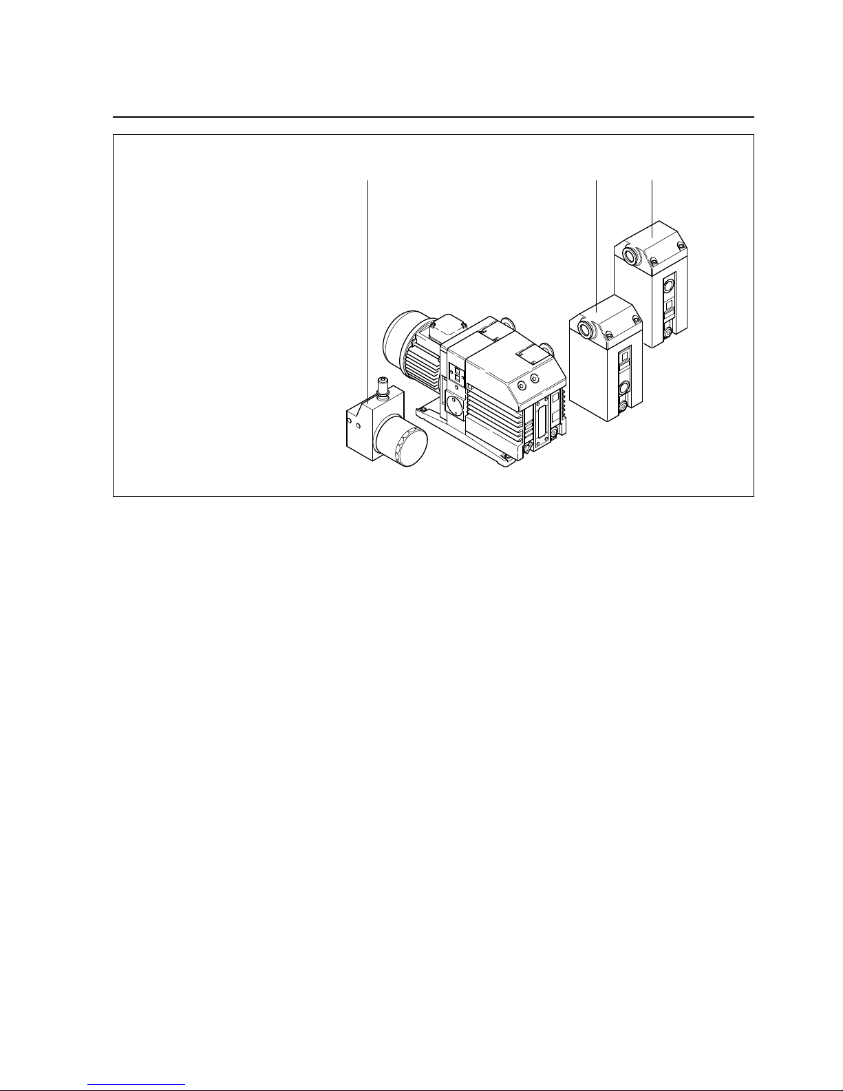
Key to Fig. 1
1 Oil filter OF 4-25
2 Exhaust filter AF 4-8
3 Condensate trap AK 4-8
Fig. 1 TRIVAC-B with accessories
The gas ballast stops condensation of vapours in the
pump chamber up to the limit of vapour tolerance as
specified in the technical data for the pump (the data
refer to water vapour).
The gas ballast valve is opened and closed by turning
the gas ballast knob (7/5) on the front.
To enable the TRIVAC-B to be used at intake pressures
as high as 1,000 mbar, a special lubricating system was
developed featuring force-lubrication of the sliding
bearings.
An oil pump (3/6) pumps the oil from the oil reservoir
(3/5) into a pressure-lubrication system which supplies
oil to all bearing points (3/2).From there the oil enters the
pump chamber area (3/4) of the vacuum pump.
The oil pump is fitted in the front end plate on the
coupling side of the pump module.The oil suction line is
placed low, resulting in a large usable oil reser voir.
The oil is separated from the gas in the TRIVAC-B in two
steps as described above. First, small droplets are
coalesced into large drops in the internal demister (2/11)
fitted above the exhaust valve (2/10). Then, the large
drops fall into the oil reservoir as the exhaust gas is
diverted by the inner walls of the oil case.Thus a low loss
of oil is obtained. This and the large usable oil reservoir
ensure long intervals between oil changes even at high
intake pressures.
Description
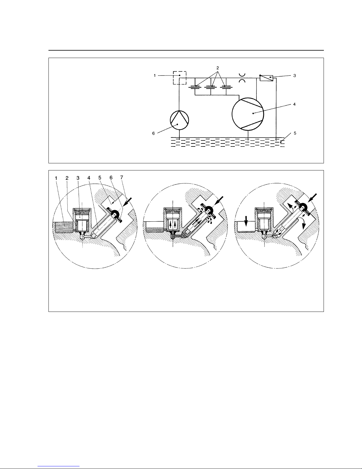
The vacuum is maintained by the TRIVAC-B through an
integrated hydropneumatic anti-suckback valve (2/3)
which is controlled via the oil pressure.
During operation of the TRIVAC-B the control piston (4/3)
remains sealed against a spring (4/2) by the oil pressure.
The valve disc (4/6) of the anti-suckback valve is held at
the lower position by its own weight (valve open). When
the pump stops (because it has been switched off or
because of a failure), the oil pressure drops and the
spring (4/2) presses the control piston (4/3) up. Thus a
connection is provided between the oil case or the oil
reservoir (4/1) and the piston (4/4) of the anti-suckback
valve. Due to the pressure difference between the oil
case and the intake port the oil presses the piston (4/4)
up and the valve plate (4/6) against the valve seat (4/5).
The quantity of oil in the oil reservoir (4/1) prevents the
entry of air into the intake port (2/1) at the beginning of
this process.
After the oil has flowed out from the reservoir and when
the valve plate rests on the valve seat, air follows in,
which vents the pump chamber and forces the v alve disc
(4/6) against its seat. This effectively prevents
backstreaming of oil. The anti-suckback valve (2/3)
operates independently of the operating mode of the
pump, i.e.also with gas ballast.
4
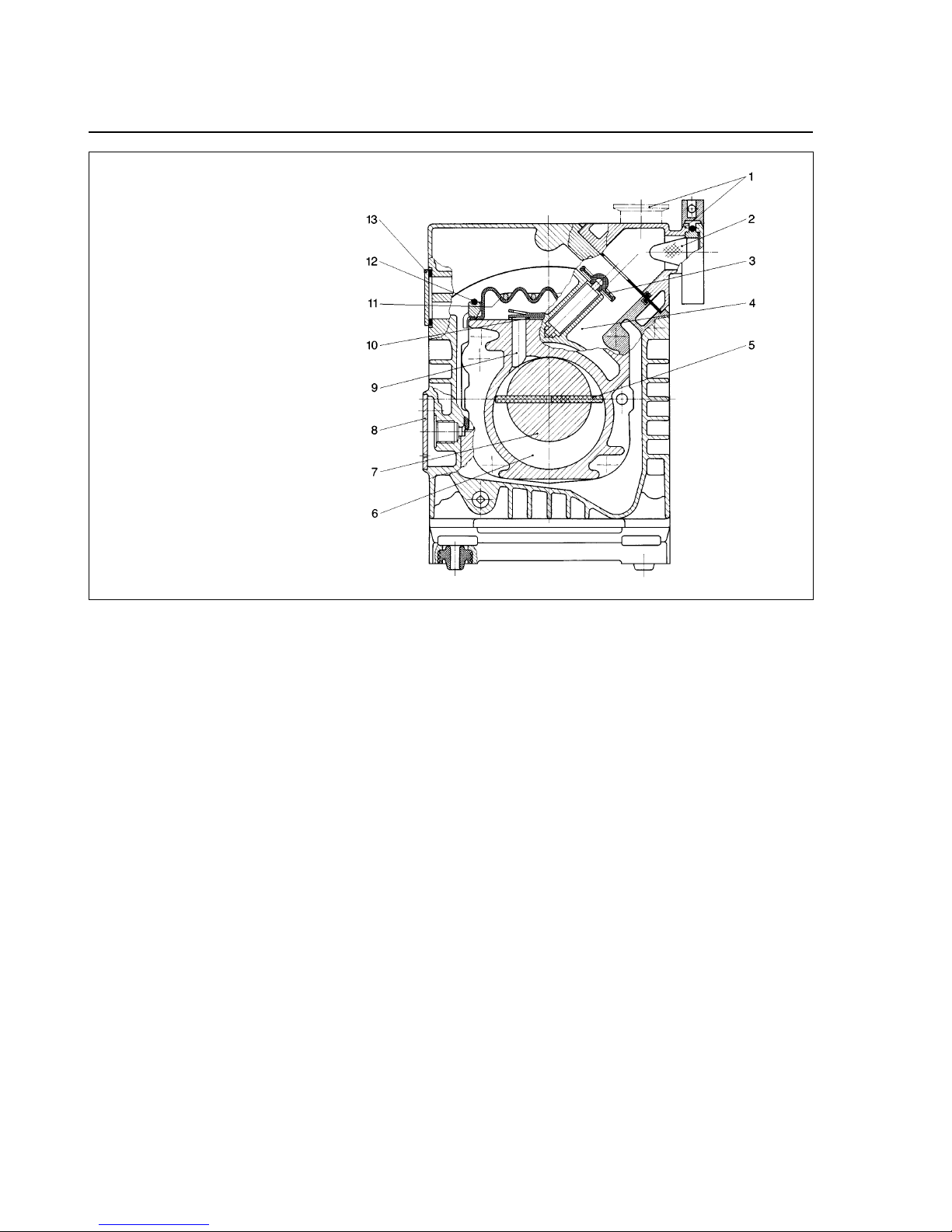
Fig. 2 Sectional drawing of the TRIVAC-B
Key to Fig. 2
1 Intake port
2 Dirt trap
3 Anti-suckback valve
4 Intake channel
5 Vanes
6 Pump chamber
7 Rotor
8 Cover plate, connection for inert gas ballast
9 Exhaust channel
10 Exhaust valve
11 Internal demister
12 Spring buckles
13 Cover plate, connection for oil filter
Description
1.2 Supplied Equipment
The equipment supplied with the TRIVAC-B pump
includes:
Pump with motor, including initial filling of N 62, HE-200
oil or Arctic oil SHC 244
Ref. No.200 28 229 (for Cat. No. 113 08 and 113 18)
1 centering ring,
1 centering ring with dirt trap,
2 clamping rings DN 16 KF.
5
As protection during shipment, the connection ports are
each blanked off by rubber diaphragms and supporting
rings.
TRIVAC-B pumps with single-phase AC motor are
supplied ready to operate with switch, built-in thermal
motor protection switch, mains cable (2 m) and mains
plug.
For TRIVAC-B pumps with three-phase AC motor, the
switch, motor protection switch, mains cable etc. are not
included but can be delivered upon request with motor
protection switch, mains plug and mains cable.
Fig. 3 Schematic of the lubr icating system
Fig. 4 Hydropneumatic anti-suckback valve
Key to Fig. 3
1 Accessories
2 Bearings
3 Non-return valve
4 Pump chamber of the TRIVAC
5 Oil reservoir
6 Oil pump
Key to Fig. 4
1 Oil reservoir 5 Valve seat
2 Spring 6 Valve disk
3 Control piston 7 Gas inlet
4 Anti-suckback piston
Description
1.3 Accessories
Cat. No. / Ref. No.
Condensate trap AK 4-8, DN 16 KF . . . . . . . . . .188 06
Exhaust filter AF 4-8, DN 16 KF . . . . . . . . . . . . .189 06
Drain tap for condensate trap, exhaust filter,
oil drain of the pump,
vacuum-tight . . . . . . . . . . . . . . . . . . . . . . . . . . .188 91
oil tight . . . . . . . . . . . . . . . . . . . . . . . . . . . . . . .188 90
Exhaust filter with lubricant return
AR 4-8, DN 16 KF . . . . . . . . . . . . . . . . . . . . . . .189 20
Dust filter FS 2-4 . . . . . . . . . . . . . . . . . . . . . . . .186 05
Fine vacuum adsorption trap FA 2-4
(with zeolite) . . . . . . . . . . . . . . . . . . . . . . . . . . .187 05
Adsorption trap
(with aluminium oxide) . . . . . . . . . . . . . . . . . . . .854 14
(with cryo insert) . . . . . . . . . . . . . . . . . . . . . . . .854 17
Cold trap TK 4-8 . . . . . . . . . . . . . . . . . . . . . . . .188 20
Oil filter OF 4-25 . . . . . . . . . . . . . . . . . . . . . . . .101 91
Chemical filter CF 4-25 . . . . . . . . . . . . . . . . . . .101 96
Adapter for gas ballast port
M 16 x 1.5 – DN 16 KF . . . . . . . . . . . . . . . . . . .168 40
M 16 x 1.5 – 3/8 inch NPT . . . . . . . . . . . . .99 175 011
Oil N 62 1l 177 01
5l 177 02
20 l 177 03
Arctic oil SHC 244 1l 200 28 229
(Order from LH Cologne, Germany)
Oil HE-200 1 qt 98 198 006
12 qt case 98 198 049
1 gal 98 198 007
5 gal 98 198 008
(Order from LHVP, Export Pa., USA)
The oil grades N 62 and HE-200 are interchangeable.
Special oils upon request.
Only use the kind of oil specified by
Leybold. Alternative types of oil are
specified upon request.
1.4 Spare Parts
Set of gaskets 197 20
Pump module, complete S 4 B 200 10 988
D 4 B 200 10 989
S 8 B 200 10 990
S 8 B 200 10 990
D 8 B 200 10 991
Module-gasket 200 10 730*)
Oil case gasket 200 10 733*)
Internal demister S/D 4 B 390 26 010*)
S/D 8 B 390 26 011*)
*) included in gasket set
1.5 Transportation
• Pumps which are filled with operating
agents must only be moved while
standing upright. Otherwise oil may
escape. Avoid any other orientations
during transport.
• Check the pump for the presence of any
oil leaks, since there exists the danger
that someone may slip on spilt oil.
• When lifting the pump you must make
use of the crane eyes provided on the
pump for this purpose; also use the
recommended type of lifting device.
6
Caution
Caution
Warning
Description
7
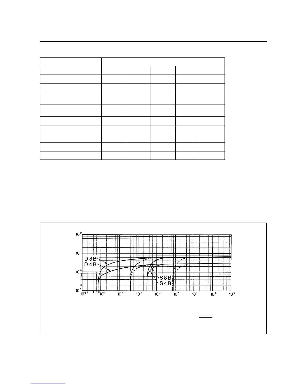
Fig. 5 Pumping speed characteristics of the TRIVAC S 4 B to TRIVAC D 8 B, 50 Hz operation, SI units
m3· h
-1
m3· h
-1
mbar
mbar
mbar
DN
cm
3
IP
S 4 B
4.8
4.2
< 4 · 10
-2
< 1
30
16 KF
300/1000
54
D 4 B
4.8
4.2
< 1 · 10
-4
< 5 · 10
-3
40
16 KF
300/800
54
S 8 B
9.7
8.5
< 4 · 10
-
2
< 1
40
16 KF
300/800
54
50Hz operation, SI units
D 8 B
9.7
8.5
< 1 · 10
-4
< 5 · 10
-3
25
16 KF
300/900
54
Nominal pumping speed*
Pumping speed*
Ultimate partial pressure
without gas ballast*
Ultimate total pressure
with gas ballast*
Water vapour tolerance*
Connection ports
Oil filling min./max.
Type of protection
* as per DIN 28 400 and following numbers
1) Weight for the version with single-phase motor 230 V, 50 Hz
1.6 Technical Data
with gas ballast
without gas ballast
kg 15.7 18.7 18.7 21.2Weight
1)
We can only guarantee that the pump will
meet its specifications when using the type
of lubricant which has been specified by us.
Caution
Pressure
Pumping speed
Description
8
Motor related data
n
m
l
ca
b
1
o
h
1
h
h
2
h
3
b
2
b
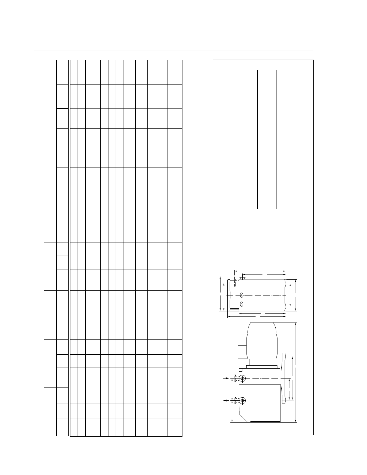
Fig. 6 Dimensional drawing for the TRIVAC rotary vane pumps (Dimensions a, l, b to b
2
and h
1
are approximate)
abb
1
b
2
chh
1
h
2
h
3
mno
S/D 4 B 75 162 147 132 100 265 215 200 230 198 99 108
S 8 B 75 162 147 132 100 265 215 200 230 198 99 108
D 8 B 100 162 147 132 100 265 215 200 230 198 99 108
dimensions in mm
1)
Motor with UL cable NEMA 5-158 and 2.5 m long cable
S 4 B
D 4 B
S 8 B
D 8 B
Cat. No. l (mm)
W (kg)
Cat. No. l (mm)
W (kg) Cat. No. l (mm)
W (kg)
Cat. No.
l (mm)
W (kg)
Motor connection voltage, frequency
Motor
power
Rated
current
Speed
Motor noise
level
Order No.for
the motor
102 45
–
–
103 01
103 02
103 03
103 04
102 46
–
–
103 05
103 06
103 07
430
430
430
430
470
430
430
430
223
15.7
15.7
15.7
15.7
19.7
13.4
13.4
15.0
7.8
–
112 45
–
113 01
113 02
113 03
103 04/08
1)
–
112 46–113 05
113 06
113 07
430
430
430
430
470
430
430
430
223
18.7
18.7
18.7
18.7
19.7
16.4
16.4
18
10.6
–
102 55
–
103 11
103 12
103 13
103 14
–
102 56–103 15
103 16
103 17
430
430
430
430
470
430
430
430
223
18.7
18.7
18.7
18.7
19.7
16.1
16.1
17.7
10.3
–
–
112 55
113 11
113 12
113 13
113 14/18
1)
–
–
112 56
113 15
113 16
113 17
455
455
455
455
495
455
455
455
248
21.2
21.2
21.2
21.2
25.2
18.6
18.6
18.6
12.8
430
1 ~ , 230 V, 50 Hz
1 ~ , 230 V, 50 Hz
1 ~ , 230 V, 50 Hz
1 ~ , 220 V, 50 Hz / 60 Hz
1 ~ , 240 V, 50 Hz / 60 Hz
1 ~ , 115 V, 60 Hz
1 ~ , 100 V, 50 Hz; 110 V, 60 Hz
3 ~ , 230/400 V, 50 Hz
250/440 V, 60 Hz
3 ~ , 230/400 V, 50 Hz
250/440 V, 60 Hz
3 ~ , 230/400 V, 50 Hz
250/440 V, 60 Hz
3 ~ , 400 V, 50 Hz
3 ~ , 230/400 V, 50 Hz
without motor
180 W
250 W
370 W
370 W
370 W
370 W
370 W
180 W
250 W
370 W
370 W
370 W
–
2.5 A
2.8 A
2.9 A
3 A
2.7 A
5.6 A
8.7/6.1 A
2.1/1.2 A
1.75/1 A
2.25/1.3 A
1.9/1.1 A
1.95/1.12A
1.73/1.0 A
1.12 A
1.92/1.11A
–
1400
1400
1400
1400/1660
1380/1680
1700
1400/1700
1400
1700
1400
1700
1970
1680
1370
1395
–
47 dB (A)
47 dB (A)
47 dB (A)
49/51 dB (A)
49/51 dB (A)
51 dB (A)
53/56 dB (A)
47 dB (A)
51 dB (A)
47 dB (A)
51 dB (A)
46 dB (A)
50 dB (A)
46 dB (A)
45 dB (A)
48 dB (A)
380 66 010
380 66 007
380 66 008
200 10 401
200 10 402
200 10 403
200 10 404
380 66 009
380 66 005
380 66 006
200 10 405
200 10 406
–
 Loading...