

Leybold vacuum TRIVAC D 16 B, TRIVAC D 25 B Operating Instructions Manual
GA 01.202/10.02
TRIVA C®B
Rotary Vane Vacuum Pump
D 16 B / D 25 B
Cat.-No.
112 65/66/75/76
113 25/27/28/29
113 33/35/36/37/38/39/48
113 70/72/80/82
Operating Instructions
Vacuum Solutions Application Support Service
LEYBOLD VACUUM

GA 01.202/10.02 - 08/01
Contents
2
Contents
Page
IMPORTANT SAFETY CONSIDERATIONS . .4
1 Description . . . . . . . . . . . . . . . . . . . . . . . . . .6
1.1 Function . . . . . . . . . . . . . . . . . . . . . . . . . . . . .6
1.2 Supplied Equipment . . . . . . . . . . . . . . . . . . . .8
1.3 Accessories . . . . . . . . . . . . . . . . . . . . . . . . . .9
1.4 Spare Parts . . . . . . . . . . . . . . . . . . . . . . . . . .9
1.5 Transportation . . . . . . . . . . . . . . . . . . . . . . . .9
1.6 Technical Data . . . . . . . . . . . . . . . . . . . . . . .10
2 Operation . . . . . . . . . . . . . . . . . . . . . . . . . .12
2.1 Installation . . . . . . . . . . . . . . . . . . . . . . . . . .12
2.2 Connection to the System . . . . . . . . . . . . . . .12
2.3 Electrical Connection . . . . . . . . . . . . . . . . . .12
2.4 Start-up . . . . . . . . . . . . . . . . . . . . . . . . . . . .14
2.5 Operation . . . . . . . . . . . . . . . . . . . . . . . . . . .15
2.6 Switching off / Shutdown . . . . . . . . . . . . . . .16
3 Maintenance . . . . . . . . . . . . . . . . . . . . . . . .17
3.1 Checking the Oil Level . . . . . . . . . . . . . . . . .17
3.2 Oil Change . . . . . . . . . . . . . . . . . . . . . . . . . .18
3.3 Cleaning the Dirt Trap . . . . . . . . . . . . . . . . . .18
3.4 Removing and Fitting the Internal Demister . .19
3.5 Disassembly and Reassembly of the
Electric Motor . . . . . . . . . . . . . . . . . . . . . . . .20
3.6 Replacing the Outer Shaft Seal . . . . . . . . . . .21
3.7 Removing and Remounting the
Pump Module . . . . . . . . . . . . . . . . . . . . . . . .22
3.8 Service at Leybold’s . . . . . . . . . . . . . . . . . . .24
3.9 Storing the Pump . . . . . . . . . . . . . . . . . . . . .24
3.10 Maintenance Plan . . . . . . . . . . . . . . . . . . . . .25
4 Troubleshooting . . . . . . . . . . . . . . . . . . . . .26
EEC Declaration of Conformity . . . . . . . . .28
EEC Manufacturer’s Declaration . . . . . . . .29
We reserve the right to modify the design and the specified data.The illustrations are not binding.
Note
We strongly recommend that you read
these Operating Instructions with care so as
to ensure optimum operation of the pump
right from the start.
Indicates procedures that must be strictly
observed to prevent hazards to persons.
Indicates procedures that must strictly be
observed to prevent damage to, or destr uction of the pump.
Figures
The references to diagrams, e.g. (1/2) consist of the Fig.
No.and the Item No. in that order.
Leybold-Service
If a pump is returned to LEYBOLD, indicate whether the
pump is free of substances damaging to health or
whether it is contaminated.
If it is contaminated also indicate the nature of the
hazard. LEYBOLD must return any pumps without a
„Declaration of Contamination“ to the sender’s address.
Disposal of Waste Oil
Owners of waste oil are entirely self-responsible for proper disposal of this waste.
Waste oil from vacuum pumps must not be mixed with
other substances or materials.
Waste oil from vacuum pumps (Leybold oils which are
based on mineral oils) which are subject to normal wear
and which are contaminated due to the influence of oxygen in the air, high temperatures or mechanical wear
must be disposed of through the locally available waste
oil disposal system.
Waste oil from vacuum pumps which is contaminated
with other substances must be marked and stored in
such a way that the type of contamination is apparent.
This waste must be disposed of as special waste.
European, national and regional regulations concerning
waste disposal need to be observed.Waste must only be
transported and disposed of by an approved waste disposal vendor.
3
GA 01.202/10.02 - 08/01
Warning
Caution
4
GA 01.202/10.02 - 08/01
IMPORTANT SAFETY CONSIDERATIONS
The Leybold TRIVAC B vacuum pump is designed for safe and efficient operation when used properly and in accordance with this manual. It is the responsibility of the user to carefully read and strictly obser ve all safety precautions
described in this section and throughout the manual. This product must be operated and maintained by trained personnel only. Consult local, state, and national agencies regarding specific requirements and regulations. Address any
further safety, operation and/or maintenance questions to your nearest Leybold Vacuum office.
Warning Failure to observe the following precautions could result in serious personal injury:
• Before beginning with any maintenance or service work on the TRIVAC B, disconnect the pump from
all power supplies.
• Do not operate the pump with any of the covers removed. Serious injur y may result.
• If exhaust gases must be collected or contained, do not allow the exhaust line to become pressurised.
• Make sure that the gas flow from the exhaust port is not blocked or restr icted in any way.
• The standard version of the TRIVAC B is not suited for oper ation in explosion hazard areas. Contact us
before planning to use the pump under such circumstances.
• Before starting up for the first time, the motor circuit (3 phase) must be equipped with a suitable
protective motor switch. Please take note of the information in these Operating Instructions or on the
electric motor (wiring diagram).
• The TRIVAC B is not suited for pumping of:
- combustible and explosive gases or vapours
- radioactive and toxic substances
- pyrophorous substances.
• Avoid exposing any par t of the human body to the vacuum.
• Never operate the TRIVAC B without a connected intake line or blank flange.
• The location at which the TRIVAC B (including its accessories) is operated should be such that angles
over 10° from the vertical are avoided.
• The location of the TRIVAC B should be such that all controls are easily accessible.
• Under certain ambient conditions the TRIVAC B may attain a temperature of over 80 °C
(176 °F).There then exists the danger of receiving burns.
Note the symbols on the pump pointing to the hazards, and in the case of a hot pump wear the required protective clothing.
• Before pumping oxygen (or other highly reactive gases) at concentrations exceeding the concentration
in the atmosphere (> 21 % for oxygen) it will be necessary to use a special pump. Such a pump will
have to be modified and de-greased, and an inert special lubricant (like PFPE) must be used.
• Before operating the TRIVAC B with atmospheric gas ballast (optional) check first compatibility with the
pumped media so as to avoid hazardous conditions during operation right from the start.
• Before commissioning the TRIVAC B, make sure that the media which are to be pumped are compatible with each other so as to avoid hazardous situations.
All relevant safety standards and regulations must be obser ved.
• It is recommended to always operate the TRIVAC B with a suitable exhaust line which is properly
connected. It must slope down and away from the pump.
• When moving the TRIVAC B always use the allowed means.
A lifting eye is provided as standard on the pump.

5
GA 01.202/10.02 - 08/01
Failure to observe the following precautions could result in damage to the pump:
• Do not allow the ingestion of small objects (screws, nuts, washers, pieces of wire, etc.)
through the inlet port. Always use the screen which is supplied with every pump.
• Do not use the pump for applications that produce abrasive or adhesive powders or
condensable vapours that can leave adhesive or high viscosity deposits. Please contact Leybold Sales
or Service to select a suitable separator. Also pease contact Leybold Sales or Ser vice when planning
to pump vapours other than water vapour.
• This pump is suited for pumping water vapour within the specified water vapour tolerance limits.
• Avoid vapours that can condense into liquids upon compression inside the pump, if these substances
exceed the vapour tolerance of the pump (> 25 mbar for water vapour).
• Before pumping vapours, the TRIVAC B should have attained its operating temperature, and the gas
ballast should be set to position I (position 0 = closed, position I = max. water vapour tolerance, 25
mbar).
The pump will have attained its operating temperature about 30 min utes after starting the pump.During
this time the pump should be separated from the process, by a valve in the intake line, for example.
• In the case of wet processes we recommend the installation of liquid separators upstream and downstream of the pump as well as the use of the gas ballast.
• The exhaust line should be laid so that it slopes down and away from the pump so as to prevent condensate from backstreaming into the pump.For this preferably use the flange on the side of the motor.
• The entry of particles and fluids must be avoided under all circumstances.
• Reactive or aggressive substances in the pump chamber may impair the operating oil or modify it.
In addition, such substances may be incompatible with the materials of the pump (Viton, grey cast iron,
aluminium, steel, resins, glass etc.).
• Corrosion, deposits and cracking of oil within the pump are not allowed.
This information will help the operator to obtain the best performance from the equipment:
• Normal amounts of humidity within the range of the pump’s vapour tolerance will not significantly affect
pump performance when the gas ballast is active.Preferably use the e xhaust flange located on the side
of the motor.
Caution:
In the case of custom pumps (with a Cat. No. deviating from the Cat No. stated in the
EC Declaration of Conformity) please note the information provided on a separate sheet.
Caution
Note
Description
6
GA 01.202/10.02 - 08/01
123
1 Description
TRIVAC-B pumps are oil-sealed rotary vane pumps.The
TRIVAC D16 B and D 25 B are dual-stage pumps. The
number in the type designation (16 or 25) indicates the
pumping speed in m3· h-1.
TRIVAC-B pumps can pump gases and vapours and
evacuate vessels or vacuum systems in the fine vacuum
range. Those of standard design are not suitable for
pumping greater than atmospheric concentrations of
oxygen, hazardous gases, or extremely aggressive or
corrosive media.
The drive motor of the TRIVAC-B is directly flanged to
the pump at the coupling housing. The pump and motor
shafts are directly connected by a flexible coupling.The
bearing points of the pump module are force lubricated
sliding bearings. All controls as well as the oil-level glass
and the nameplate are arranged on the front.All connections are to be found at the sides of the pump.The oillevel glass is provided with prisms for better obser vation
of the oil level.
The pump module consists of assembly parts which are
pin-fitted so as to allow easy disassembly and reassembly. The pump module can be easily removed without
special tools.
1.1 Function
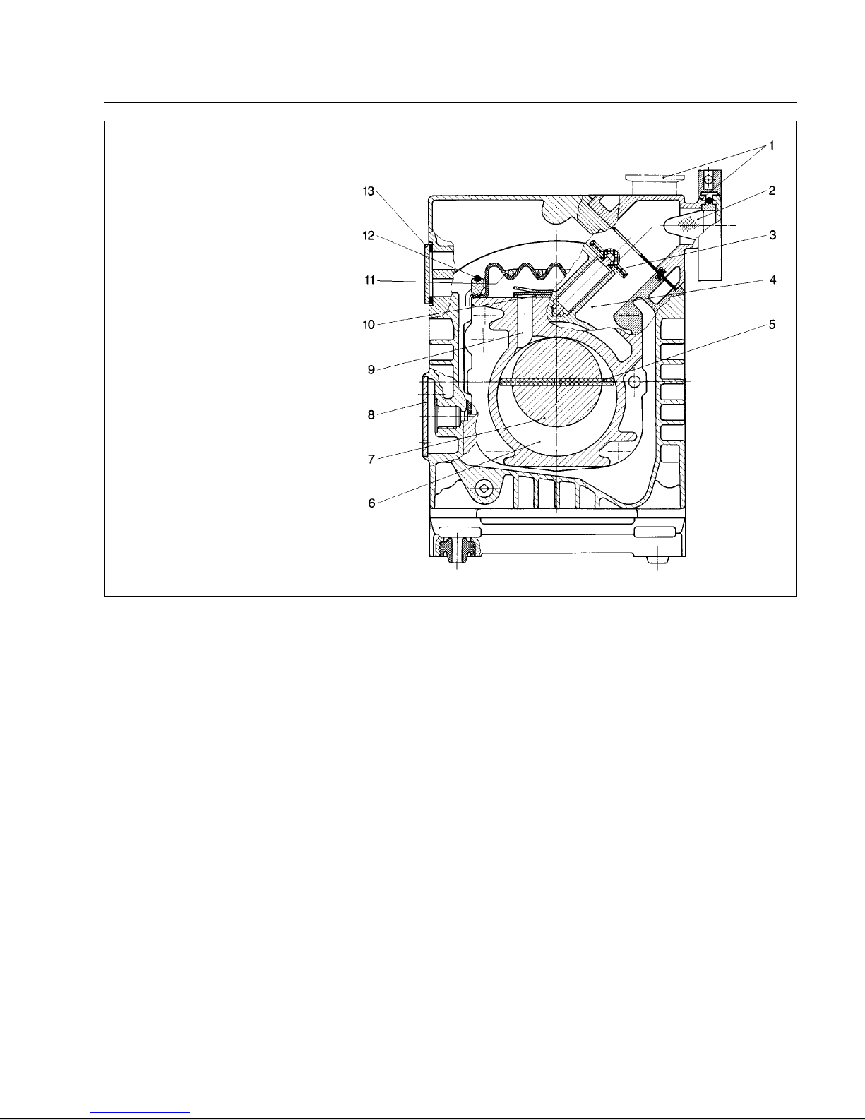
The rotor (2/7), mounted eccentrically in the pump housing (2/6), has two radially sliding vanes (2/5) which divide the pump chamber into several compartments. The
volume of each compartment changes periodically with
the rotation of the rotor.
As a result, gas is sucked in at the intake port (2/1).The
gas passes through the dirt trap sieve (2/2), flows past
the open anti-suckback valve (2/3) and then enters the
pump chamber (2/6). In the pump chamber, the gas is
passed on and compressed, after the inlet aperture is
closed by the vane.
The oil injected into the pump chamber is used for sealing and lubricating.The slap noise of the oil in the pump
which usually occurs when attaining the ultimate pressure is prevented by admitting a ver y small amount of air
into the pump chamber.
The compressed gas in the pump chamber is ejected
through the exhaust valve (2/10). The oil entrained in the
gas is coarsely trapped in the internal demister (2/11);
there the oil is also freed of mechanical impurities. The
gas leaves the TRIVAC-B through the exhaust por t.
During compression, a controlled amount of air - the socalled gas ballast - can be allowed to enter the pump
chamber by opening the gas ballast valve (position I).
The gas ballast stops condensation of vapours in the
pump chamber up to the limit of water vapour tolerance
as specified in the technical data for the pump.
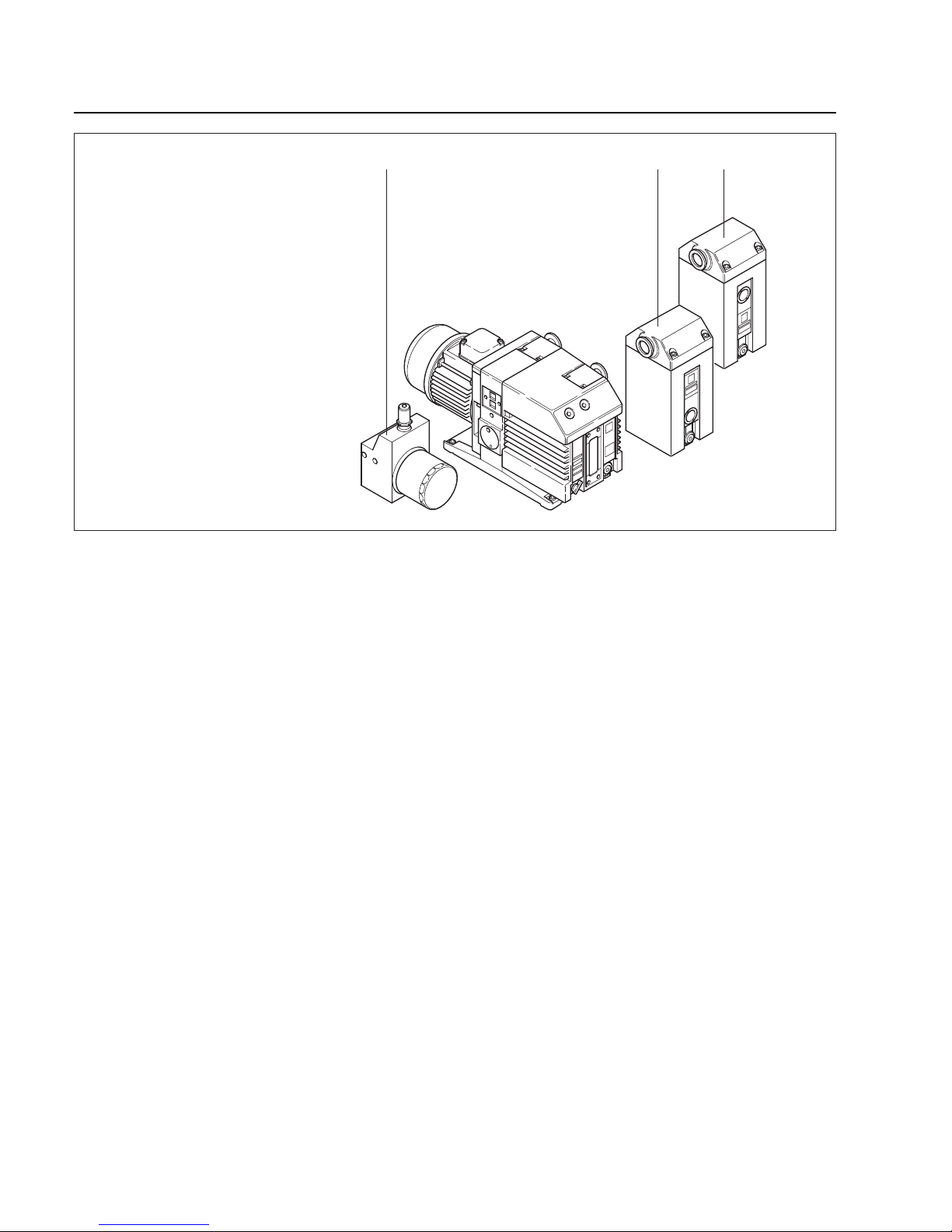
Key to Fig. 1
1 Oil filter OF 4-25
2 Exhaust filter AF 16-25
3 Condensate trap AK 16-25
Fig. 1 TRIVAC-B with accessor ies
Description
7
GA 01.202/10.02 - 08/01
The gas ballast valve is opened (position I) and closed
(position 0) by turning the gas ballast knob (7/5) on the
front.
To enable the TRIVAC-B to be used at intake pressures
as high as 1,000 mbar, a special lubricating system was
developed featur ing force-lubrication of the sliding bearings.
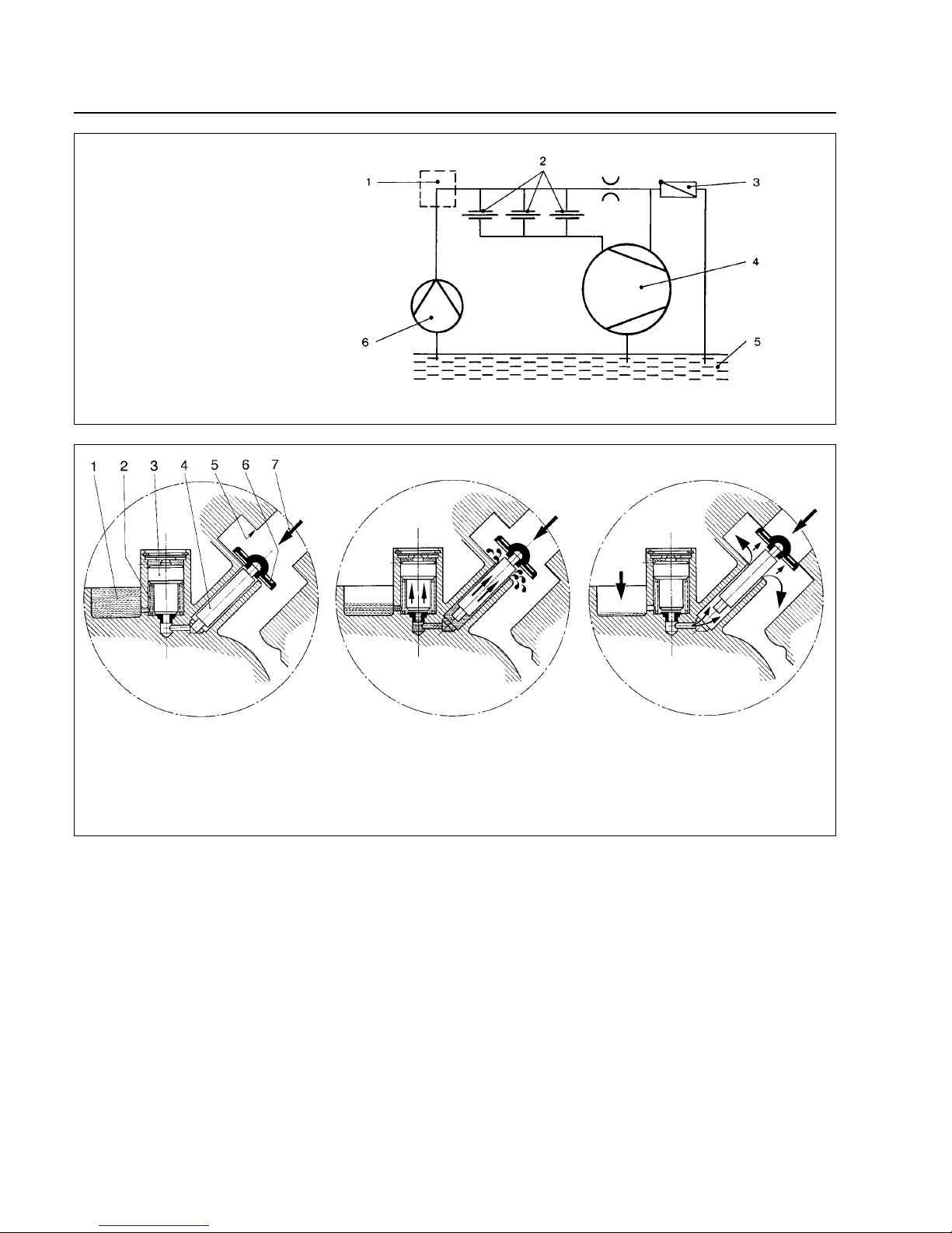
An oil pump (3/6) pumps the oil from the oil reservoir
(3/5) into a pressure-lubrication system which supplies
oil to all bearing points (3/2).From there the oil enters the
pump chamber area (2/6) of the vacuum pump.
The oil pump is fitted in the front end plate on the coupling side of the pump module.The oil suction line is placed low, resulting in a large usable oil reser voir.
The oil is separated from the gas in the TRIVAC-B in two
steps as described above.First, small droplets are coalesced into large drops in the internal demister (2/11) fitted
above the e xhaust v alve (2/10).Then, the large drops fall
into the oil reservoir as the exhaust gas is diverted by the
inner walls of the oil case.Thus a low loss of oil is obtained. This and the large usable oil reservoir ensure long
intervals between oil changes even at high intake pressures.
The vacuum is maintained by the TRIVAC-B by an integrated hydropneumatic anti-suckback valve (2/3) which
is controlled via the oil pressure.
During operation of the TRIVAC-B the control piston (4/3)
remains sealed against a spring (4/2) by the oil pressure.The valve disc (4/6) of the anti-suckback valve is held
at the lower position by its own weight (valve open).
When the pump stops (because it has been switched off
or because of a failure), the oil pressure drops and the
spring (4/2) presses the control piston (4/3) up. Thus a
connection is provided between the oil case or the oil
reservoir (4/1) and the piston (4/4) of the anti-suckback
valve. Due to the pressure difference between the oil
case and the intake port the oil presses the piston (4/4)
up and the valve plate (4/6) against the valve seat (4/5).
The quantity of oil in the oil reservoir (4/1) prevents the
entry of air into the intake port (2/1) at the beginning of
this process.
After the oil has flowed out from the reservoir and when
the valve plate rests on the valve seat, air follows in,
which vents the pump chamber and forces the v alve disc
(4/6) against its seat. This effectively prevents backstreaming of oil.The anti-suckback valve (2/3) operates independently of the operating mode of the pump, i.e. also
with gas ballast.
Fig. 2 Sectional drawing of the TRIVAC-B
Key to Fig. 2
1 Intake port
2 Dirt trap
3 Anti-suckback valve
4 Intake channel
5 Vanes
6 Pump chamber
7 Rotor
8 Cover plate, connection for inert gas ballast
9 Exhaust channel
10 Exhaust valve
11 Internal demister
12 Spring buckles
13 Cover plate, connection for oil filter
Description
8
GA 01.202/10.02 - 08/01
1.2 Supplied Equipment
The equipment supplied with the TRIVAC-B pump includes:
Pump with motor, including initial filling of N 62 or
HE-200 oil, or Artic oil (Cat. Nos. 113 29 and 113 39),
or Anderol RCF-E 96 N (Cat. Nos. 113 33).
1 centering ring,
1 centering ring with dirt trap,
2 clamping rings DN 25 KF.
As protection during shipment, the connection ports are
each blanked off by rubber diaphragms and supporting
rings.
TRIVAC-B pumps with single-phase AC motor are supplied ready to operate with switch, built-in thermal motor
protection switch, mains cable (2 m) and mains plug.
For TRIVAC-B pumps with three-phase AC motor, the
switch, motor protection switch, mains cable etc. are not
included.
Fig. 3 Schematic of the lubricating system
Fig. 4 Hydropneumatic anti-suckback valve
Key to Fig. 3
1 Accessories
2 Bearings
3 Non-return valve
4 Pump chamber of the TRIVAC
5 Oil reservoir
6 Oil pump
Key to Fig. 4
1 Oil reservoir 5 Valve seat
2 Spring 6 Valve disk
3 Control piston 7 Gas inlet
4 Anti-suckback piston
Description
9
GA 01.202/10.02 - 08/01
1.3 Accessories
Cat. No. / Ref. No.
Condensate trap AK16-25, DN 25 KF 188 11
Exhaust filter AF16-25, DN 25 KF 189 11
Drain tap for condensate trap, exhaust filter,
oil drain of the pump,
vacuum-tight 190 90
oil tight 190 90
Exhaust filter with lubricant return
AR 16-25, DN 25 KF 189 21
Exhaust filter with Iubricant return ARS 16-25 189 56
Dust filter 186 10
Dust separator 186 11
Molecular filter 186 12
Fine vacuum adsorption trap (with zeolite) 187 10
Adsorption trap
(with aluminium oxide) 854 15
Oil filter OF 4-25 101 91
Chemical filter CF 4-25 101 96
Chemical filter with safety cut-off valve CFS 101 76
Adapter for gas ballast port
M 16 x 1.5 - DN 16 KF 168 40
M 16 x 1.5 - 3/8 inch NPT 99 175 011
Oil N 62 1l 177 01
5l 177 02
20 l 177 03
Arctic oil SHC 224 1 l 200 28 181
(order from Leybold Cologne, Germany)
Anderol RCF-E 96 N 1 l 200 39 839
Oil HE-200 1 qt 98 198 006
(order from 12 qt case 98 198 049
LHVP, Export Pa., 1 gal 98 198 007
USA) 5 gal 98 198 008
The oil grades N 62 and HE-200 are interchangeable.
Special oils upon request.
Only use the kind of oil specified by Leybold. Alternative types of oil are specified
upon request.
1.4 Spare Parts
Set of gaskets 197 21
Pump module, complete D 16 B 200 10 956
D 25 B 200 10 960
Module-gasket 200 10 736*)
Oil case gasket 200 10 737*)
Internal demister D 16 B 390 26 012*)
D 25 B 390 26 013*)
*) included in gasket set
1.5 Transportation
• Pumps which are filled with operating
agents must only be moved while standing
upright. Otherwise oil may escape. Avoid
any other orientations during transport.
• Check the pump for the presence of any
oil leaks, since there exists the danger that
someone may slip on spilt oil.
• When lifting the pump you must make use
of the crane eyes provided on the pump for
this purpose; also use the recommended
type of lifting device.
Caution
Caution
Warning
 Loading...