

Leybold vacuum TRIVAC B Operating Instructions Manual
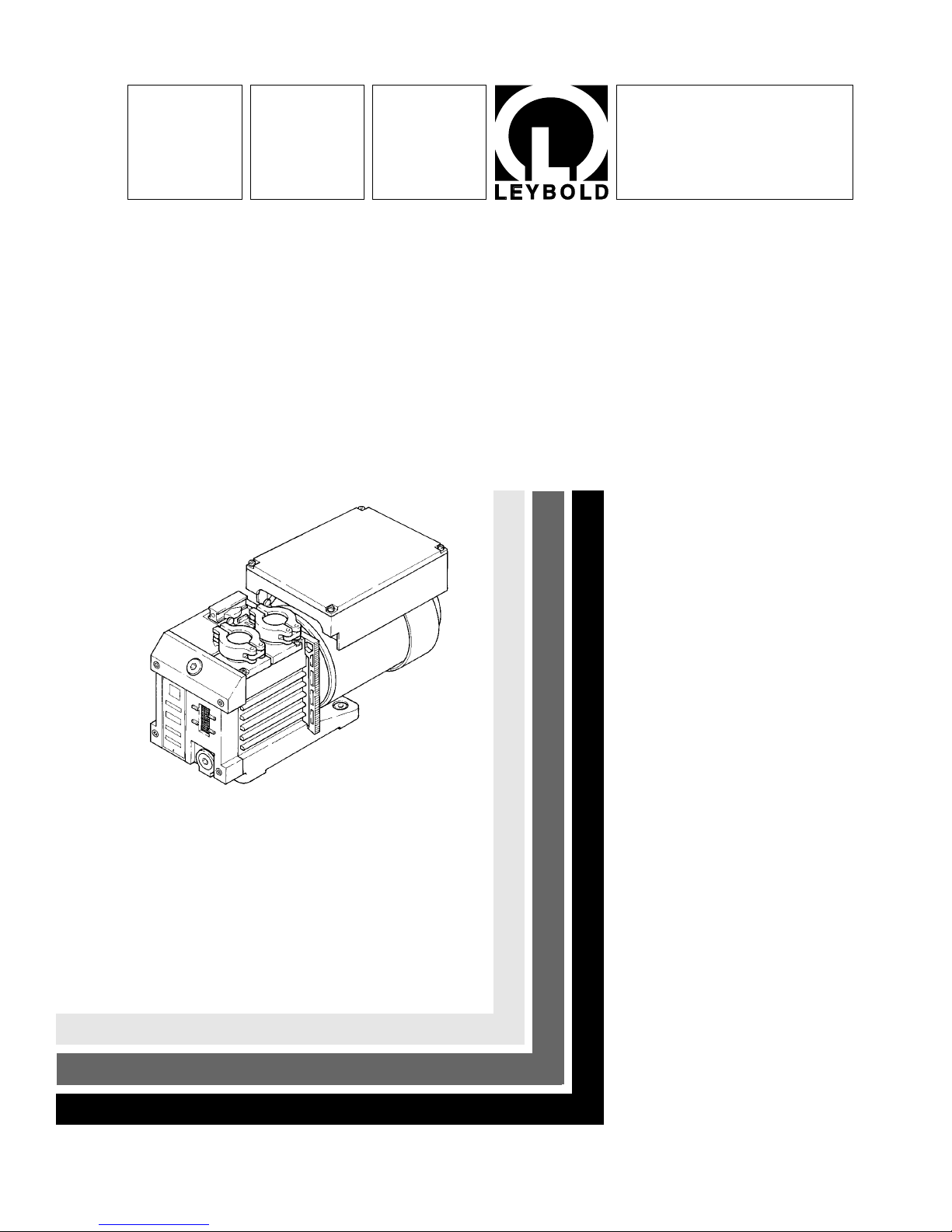
TRIVAC®B
Rotary Vane Vacuum Pump
S/D 1,6 B
Cat. No.
102 25/26/27
112 25/26/27/31
Operating Instructions
Vacuum Pumps Instrumentation Fittings and Valves LEYBOLD VACUUM
GA 01.200/8.02
Contents
2
Contents
Page
1 Description . . . . . . . . . . . . . . . . . . . . . . . . . . 3
1.1 Function . . . . . . . . . . . . . . . . . . . . . . . . . . . . . 3
1.2 Supplied equipment . . . . . . . . . . . . . . . . . . . . . 4
1.3 Accessories . . . . . . . . . . . . . . . . . . . . . . . . . . . 4
1.4 Spare parts . . . . . . . . . . . . . . . . . . . . . . . . . . . 5
1.5 Transportation . . . . . . . . . . . . . . . . . . . . . . . . . 5
1.6 Technical data . . . . . . . . . . . . . . . . . . . . . . . . . 6
2 Operation . . . . . . . . . . . . . . . . . . . . . . . . . . . . 7
2.1 Installation . . . . . . . . . . . . . . . . . . . . . . . . . . . . 7
2.2 Connection to the system . . . . . . . . . . . . . . . . 7
2.3 Electrical connection . . . . . . . . . . . . . . . . . . . . 8
2.4 Start-up . . . . . . . . . . . . . . . . . . . . . . . . . . . . . . 9
2.4.1 Areas of application . . . . . . . . . . . . . . . . . . . . . 9
2.5 Operation . . . . . . . . . . . . . . . . . . . . . . . . . . . . 9
2.5.1 Pumping of non-condensable gases . . . . . . . . 9
2.5.2 Pumping of condensable gases and vapours . . 9
2.5.3 Operating temperature . . . . . . . . . . . . . . . . . . 10
2.6 Switching off/shutdown . . . . . . . . . . . . . . . . . 10
2.6.1 Shutdown through monitoring components . . . 10
2.6.2 Failure of the control system or
the mains power . . . . . . . . . . . . . . . . . . . . . 10
3 Maintenance . . . . . . . . . . . . . . . . . . . . . . . . 11
3.1 Checking the oil level . . . . . . . . . . . . . . . . . . . 11
3.1.1 Checking the condition of N 62 or HE-200 oil . 11
3.2 Oil change . . . . . . . . . . . . . . . . . . . . . . . . . . . 12
3.3 Cleaning the dirt trap . . . . . . . . . . . . . . . . . . . 13
3.4 Disassembly and reassembly of the
electric motor . . . . . . . . . . . . . . . . . . . . . . . 13
3.5 Removing and remounting the pump module . 14
3.6 Exchanging the shaft seal, cleaning the oil
injection and silencing nozzle . . . . . . . . . . . 14
3.7 Leybold service . . . . . . . . . . . . . . . . . . . . . . . 15
3.8 Waste disposal of used pump materials . . . . . 15
3.9 Storing the pump . . . . . . . . . . . . . . . . . . . . . . 15
3.10 Troubleshooting . . . . . . . . . . . . . . . . . . . . . . . 16
3.11 Maintenance plan . . . . . . . . . . . . . . . . . . . . . 18
EEC Declaration of Conformity . . . . . . . . . . 20
Figures
The references to figures, e.g. (1/2) consist of the Fig.
No. and the Item No. in that order.
Indicates procedures that must be strictly
observed to prevent hazards to persons.
Indicates procedures that must strictly be
observed to prevent damage to, or
destruction of the equipment.
Leybold Service
If a pump is returned to Leybold, indicate whether the
pump is free of substances damaging to health or
whether it is contaminated.
If it is contaminated also indicate the nature of the
hazard. Leybold must return any pumps without a
“Declaration of Contamination” to the sender’s address.
Disposal of waste oil
Under the amended law relating to waste disposal dated
November 1, 1986 (valid in the Federal Republic of
Germany) the disposal of used oil is subject to new
provisions. According to legislation relating to waste
disposal the so-called principle of causality is applied.
Hence, anyone in possession of used oil is responsible
for its proper disposal.
Used oils coming from vacuum pumps must not be
mixed with other substances.
Used oils from vacuum pumps (LH-oils on the basis of
mineral oils) having been affected by normal
contamination due to oxygen from the ambient air,
increases in temperature and mechanical wear, must be
disposed of as used oil in accordance with the
regulations. Used oils from vacuum pumps that have
been contaminated by other substances must be
labelled, stored and disposed of as special waste with
reference to the kind of contamination.
When disposing of used oil please observe the safety
regulations that are valid in your country.
In many countries proof of were the oil has finally been
left is required by Law and often shipping of such
contaminated waste requires permission by the
authorities. Waste disposal information is available
through:
Bundesamt für Gewerbliche Wirtschaft (BAW)
Frankfurter Str. 29-31
D-65760 Eschborn/Taunus
Phone: +49 (0)6196 4041 - Telex: 415603/04
Warning
Caution
Description
3
1 Description
TRIVAC-B pumps are oil-sealed rotary vane pumps. The
TRIVAC S 1.6 B is a single-stage pump, and the TRIVAC
D 1.6 B is a dual-stage pump. The number “1.6” in the
type designation indicates the pumping speed in
m3x h
-1
TRIVAC-B pumps can pump gases and vapours and
evacuate vessels or vacuum systems in the fine vacuum
range. Those of standard design are not suitable for
pumping greater than atmospheric concentrations of
oxygen, hazardous gases, or extremely aggressive or
corrosive media.
The drive motor of the TRIVAC-B is directly flanged to
the pump at the coupling housing. The pump and motor
shafts are directly connected by a flexible coupling. The
bearing points of the pump module are force lubricated
sliding bearings. All connections are arranged on top of
the pump. The oil-level glass is provided with prisms for
better observation of the oil level.
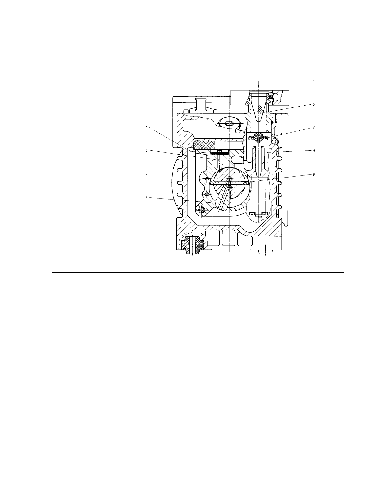
1.1 Function
The rotor (1/7), mounted eccentrically in the pump
housing (1/6) (pump chamber), has two radially sliding
vanes (1/5) which divide the pump chamber into several
compartments. The volume of each compartment
changes periodically with the rotation of the rotor.
As a result, gas is sucked in at the intake port (1/1). The
gas passes through the dirt trap sieve (1/2), flows past
the open anti-suckback valve (1/3) and then enters the
pump chamber. In the pump chamber, the gas is passed
on and compressed, after the inlet aperture is closed by
the vane.
The oil injected into the pump chamber is used for
sealing and lubricating. The slap noise of the oil in the
pump which usually occurs when attaining the ultimate
pressure is prevented by admitting a very small amount
of air into the pump chamber.
The compressed gas in the pump chamber is ejected
through the exhaust valve (1/9). The oil entrained in the
gas is trapped by diversion at the inner walls of the oil
case and is then returned to the oil reservoir.
Key to Fig. 1
1 Intake port
2 Dirt trap
3 Anti-suckback valve
4 Intake channel
5 Vanes
6 Pump chamber
7 Rotor
8 Exhaust channel
9 Exhaust valve
Fig. 1 Sectional drawing of the TRIVAC-B

The gas leaves the TRIVAC-B through the exhaust port.
During compression, a controlled amount of air – the socalled gas ballast – can be allowed to enter the pump
chamber by opening the gas ballast valve. The gas
ballast stops condensation of vapours in the pump up to
the limit of vapour tolerance as specified in the technical
data for the pump.
The gas ballast valve is opened and closed by turning
the gas ballast knob (5/2) on the front.
The lubricating system allows to employ the TRIVAC-B at
intake pressures as high as 1000 mbar.
The built-in anti-suckback valve (1/3) seals the pump’s
intake and vents the pump during shutdown. Sealing the
pump’s intake prevents oil from entering the intake line
during shutdown and holds the vacuum in the system.
The anti-suckback valve functions independently of the
pump’s operating mode, i. e. during gas ballast
operation, too.
1.2 Supplied Equipment
The equipment supplied with the TRIVAC-B pump
includes:
Pump with motor, including initial filling of N 62 or HE200 oil or Arctic oil SHC 244,
1 centering ring,
1 centering ring with dirt trap,
2 clamping rings DN 16 KF.
As protection during shipment, the connection ports are
each blanked off by a rubber diaphragm and a ring.
The pumps are equipped with a single-phase AC motor
and are supplied ready to operate with switch, built-in
thermal motor protection switch, mains cable (2 m) and
mains plug.
Description
1.3 Accessories
Cat. No. / Ref. No.
Condensate trap AK 1,6, DN 16 KF . . . . . . . . . .188 02
Exhaust filter AF 1,6, DN 16 KF . . . . . . . . . . . . .189 02
Drain tap for condensate trap, exhaust filter,
oil drain of the pump,
vacuum-tight . . . . . . . . . . . . . . . . . . . . . . . . . . .188 91
oil tight . . . . . . . . . . . . . . . . . . . . . . . . . . . . . . .188 90
Adapter DN 16 KF / DN 7 hose nozzle . . . . . . . .182 90
Oil N 62 1l 177 01
5l 177 02
20 l 177 03
Arctic oil SHC 244 1l 200 28 229
(Order from LH Cologne, Germany)
Oil HE-200 1 qt 98 198 006
12 qt case 98 198 049
1 gal 98 198 007
5 gal 98 198 008
(Order from LHVP, Expor t Pa., USA)
The oil grades N 62 and HE-200 are interchangeable.
Special oils upon request.
Only use the kind of oil specified by
Leybold. Alternative types of oil are
specified upon request.
4
Caution
Description
1.4 Spare Parts
Set of gaskets . . . . . . . . . . . . . . . . . . . . . . . . . .197 18
Pump module, complete S 1.6 B . . . . . . .200 390 37
D 1.6 B . . . . . . .200 390 38
When ordering spare parts, please indicate apart from
the type designation also the serial number of the pump.
5
1.5 Transportation
• Pumps which are filled with operating
agents must only be moved while
standing upright. Otherwise oil may
escape. Avoid any other orientations
during transport.
• Check the pump for the presence of any
oil leaks, since there exists the danger
that someone may slip on spilt oil.
•When lifting the pump you must make
use of the crane eyes provided on the
pump for this purpose; also use the
recommended type of lifting device.
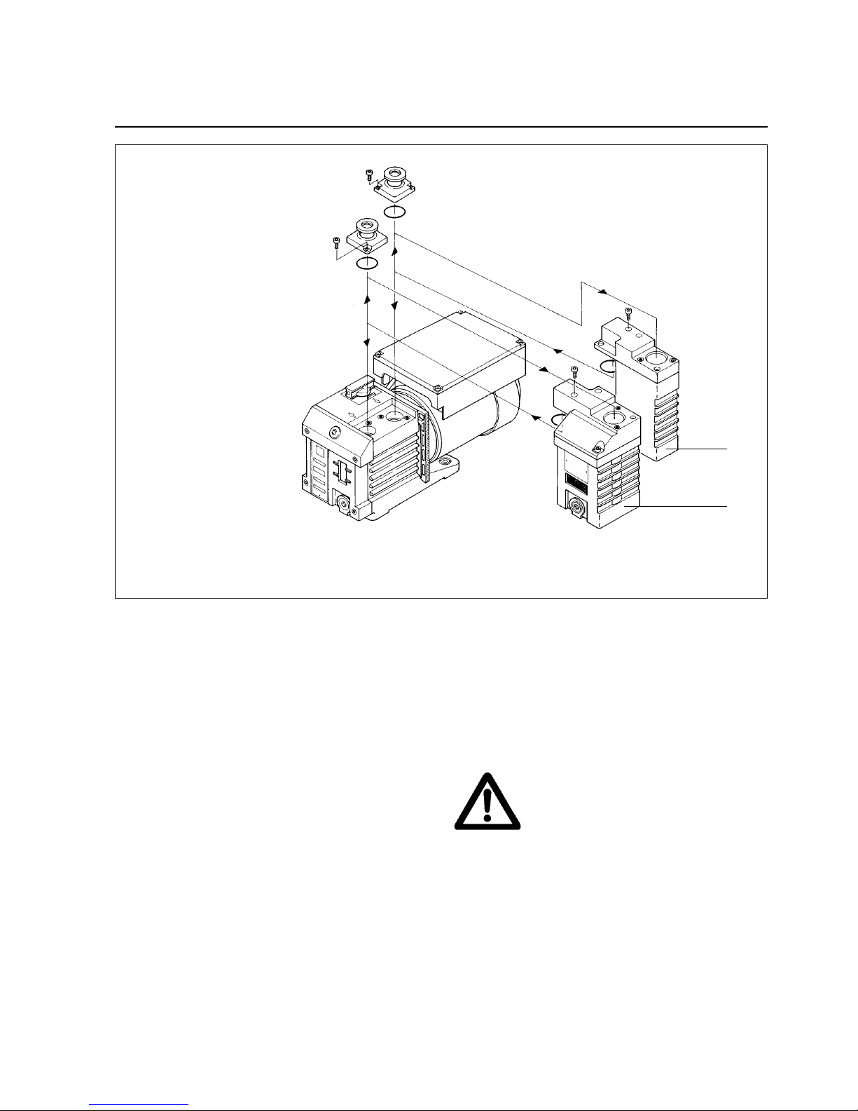
Key to Fig. 2
1 Condensate trap AK 1.6
2 Exhaust filter AF 1.6
Fig. 2 Connection of the condensate trap AK 1.6 and the exhaust filter AF 1.6 to the TRIVAC S/D 1.6 B
1
2
Warning
Caution
We can only guarantee that
the pump will meet its
specifications when using the
type of lubricant which has
been specified by us.
54
8.8
Description
6
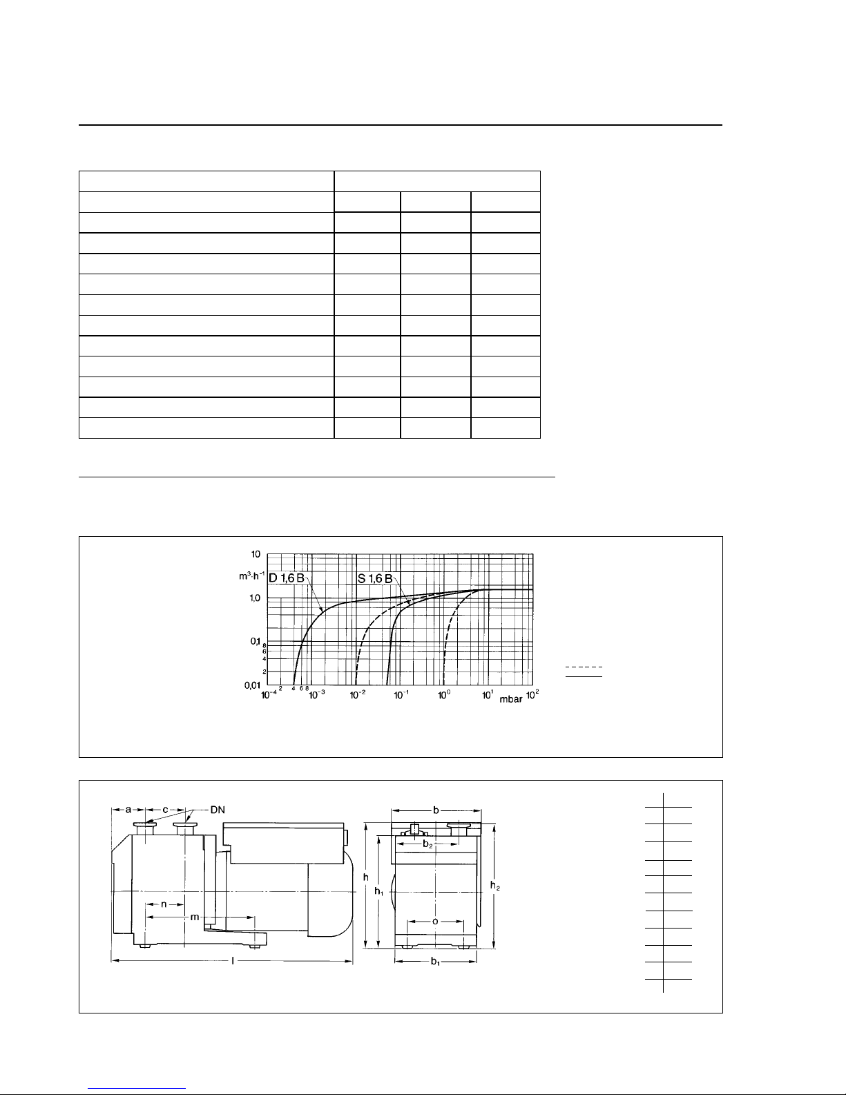
Fig. 3 Pumping speed characteristics of the TRIVAC S/D 1.6 B, 50 Hz operation, SI units
m3· h
-1
m3· h
-1
mbar
mbar
mbar
DN
cm
3
IP
S 1,6 B
1.75
1.6
5 · 10
-2
10
15
16 KF
160/250
54
D 1,6 B
1.75
1.6
4 · 10
-4
1 · 10
-1
12
16 KF
160/220
50 Hz operation, SI units
Nominal pumping speed*
Pumping speed*
Ultimate partial pressure without gas ballast*
Ultimate total pressure with gas ballast*
Water vapour tolerance*
Connection ports
Oil filling min./max.
Motor rating
*as per DIN 28 400 and following numbers
1.6 Technical Data
with gas ballast
without gas ballast
kg 8.6
Nominal speed
Caution
Pressure
Pumping speed
Weight
Type of protection
W
min
-1
100
3000 3000
100
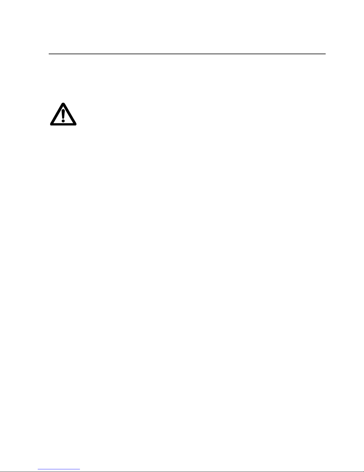
a45
b 122
b1111
b286
c53
h 169
h1151
h2167
l 324
m 146
n53
o77
Fig. 4 Dimensional drawing for the TRIVAC rotary vane pumps (dimensions a, l, b bis b1and h1are approximate)
Ordering information Cat. No. for TRIVAC withAC motor
220-240 V, 50 Hz / 230 V, 60 Hz 102 25 112 25
200-208 V, 50/60 Hz 102 26 112 26
100 V, 50/60 Hz / 115 V, 60 Hz 102 27 112 27
Operation
7
2.1 Installation
The standard pump is not suited for
installation in explosion hazard areas.When
planning such an application please contact
us first.
The TRIVAC-B pump can be set up on a flat, horizontal
surface. Rubber feet under
the coupling housing ensure that the pump can not slip.
If you wish firmly install the pump in place, insert bolts
through bore holes in the rubber feet.
Max. tilt for the pump (without further
attachment) with possibly fitted standard
accessories is 10ϒ from the vertical.
The rubber feet act as vibration absorbers.
They must therefore not be compressed by
screws. When installing the TRIVAC-B
pump, make sure that the connections and
controls are readily accessible.
The site chosen should allow adequate air
circulation to cool the TRIVAC-B (keep front
and rear unobstructed). The ambient
temperature should not exceed +40 ϒC and
not drop below +12 ϒC (see Section 2.5.3).
The max. amount of heat given off
approximately corresponds to the rated
motor power.
2.2 Connection to the
System
Before connecting the TRIVAC-B, remove the shipping
seals from the connection flanges (5/2) and (5/3).
Retain the shipping seals in case you need
to store the pump in the future.
Connect the intake and exhaust lines with a centering
ring and a clamping ring each. Use the centering ring
with dirt trap for the intake port.
Connect the intake and exhaust line using anti-vibration
bellows, without placing any strain on the pump.
Upon request the TRIVAC may also be connected via
hose nozzles.
The intake line must be clean. Deposits in the intake line
may outgas and adversely affect the vacuum. The
connecting flanges must be clean and undamaged.
The maximum throughput of the pump is equivalent to
the pumping speed of the pump (see Section 1.6).
The cross-section of the intake and exhaust
lines should be at least the same size as
the connection ports of the pump. If the
intake line is too narrow, it reduces the
pumping speed. If the exhaust line is too
narrow, overpressures may occur in the
pump; this might damage the shaft seals
and cause oil leaks. The maximum pressure
in the oil case must not exceed 1.5 bar
(absolute).
When pumping vapours, it is advisable to
install condensate traps on the intake and
exhaust sides.
Install the exhaust line with a downward
slope (lower than the pump) so as to
prevent condensate from flowing back into
the pump. If this is not possible, insert a
condensate trap.
The exhaust gases from the vacuum pump
must be safely lead away and subjected to
post-treatment as required. In order to
reduce the emission of oil vapours we
recommend the installation of an additional
exhaust filter (Leybold accessory).
Caution
Warning
2 Operation
Caution
Caution
 Loading...