

GEBRAUCHSANLEITUNG - ERSATZTEILLISTE
OPERATING INSTRUCTIONS - SPARE PARTS LIST
MODE D’EMPLOI - LISTE DES PIECES DE RECHANGE
GA02325_01
Sogevac
SV40 BI
SV40BI_couv 26/05/05 16:35 Page 1
1
GA02325_01 - 04/2005
SV40BI 27/08/56 8:49 Page 1

2
GA02325_01 - 04/2005
SV40BI 27/08/56 8:49 Page 2

Installations- und
Betriebsanleitung
Diese Installations- und Betriebsanleitungen
sind für die SOGEVAC Pumpen SV40 BI in
ihrer Standardausführung gültig.
Sonderausführungen dieser Pumpen werden
mit einer zusätzlichen Bedienungsanleitung
geliefert, deren Hinweise vorrangig zu
beachten sind.
Die SOGEVAC Vakuumpumpen sind nach
dem neuesten Stand der Technik und den
letzten bekannten sicherheitstechnischen
Regeln gebaut. Dennoch können bei
unsachgemäßer Installation oder nicht
bestimmungsgemäßem Betrieb, Gefahren und
Schäden entstehen.
Diese Betriebsanleitung ist vor der Installation
und Inbetriebnahme der Vakuumpumpe unbedingt zu lesen und zu befolgen.
Inhaltsverzeichnis : Seite
1. Allgemeine Hinweise …………………4
1.1. Sicherheitsvorschriften……………………4
1.2. Einsatzbereich ……………………………5
1.3. Funktionsprinzip …………………………5
1.4. Technische Daten …………………………6
1.5. Zubehör ……………………………………9
1.6. Transport und Verpackung ………………9
1.7. Handhabung und Lagerung ……………9
1.8. Schmierölsorten……………………………9
2. Bedienung und Betrieb ……………10
2.1. Aufstellen …………………………………10
2.2. Anschluss zur Ansaugseite ……………10
2.3. Anschluss zur Auspuffseite ……………11
2.4. Öleinfüllen ………………………………11
2.5. Elektroanschluss…………………………11
2.6. Betriebshinweise…………………………12
2.7. Abschalten ………………………………12
3. Wartung …………………………………12
3.1 Überprüfung des Ölstands ……………13
3.2. Öl wechseln………………………………13
3.3. Auswechseln der Auspuff-Filter ………14
3.4. Reinigung des Gasballastventils ………14
3.5. Reinigung des Ansaugflansch- ………14
Siebs
3.6. Überprüfung des Saugstutzen- ………15
ventils
3.7. Reinigung des Ventilatordeckels ………15
3.8. Schwimmerventil kontrollieren …………15
4. Fehlerdiagnose ………………………15
5. Ersatzteile………………………………15
6. Informationen …………………………17
Installation and operating
instructions
These installation and operating instructions
are valid for the SOGEVAC pumps SV40 BI in
their standard version.
Special versions to these pumps are delivered
with an additive document, which prevails over
the standard instructions.
The SOGEVAC vacuum pumps have been
manufactured according to the latest technical
standards and safety regulations. If not installed properly or not used as directed, dangerous situations or damage could occur.
It is mandatory that these operating instructions be read and understood prior to vacuum
pump installation and start-up.
Index : page
1. General Instructions …………………4
1.1. Safety Prescriptions ………………………4
1.2. Application range…………………………5
1.3 Principle of operation ……………………5
1.4. Technical characteristics…………………6
1.5. Accessories ………………………………9
1.6. Transport and Packing …………………9
1.7. Mounting orientation and storage ………9
1.8. Lubricants …………………………………9
2. Installation ……………………………10
2.1. Lay out ……………………………………10
2.2. Connection to intake side………………10
2.3. Connection to exhaust side ……………11
2.4. Oil filling …………………………………11
2.5. Electrical connection……………………11
2.6. Operating advice ………………………12
2.7. Shut down ………………………………12
3. Maintenance …………………………12
3.1. Oil level control …………………………13
3.2. Oil changing …………………………… 13
3.3. Exhaust filter replacement ……………14
3.4. Gas ballast valve cleaning ……………14
3.5. Inlet flange sifter cleaning………………14
3.6. Anti-suck back valve checking ………15
3.7. Fan cover cleaning ……………………15
3.8. Checking the float valve ………………15
4. Breakdown analysis ………………15
5. Spare parts ……………………………15
6. Information ……………………………17
Manuel d’installation et de
maintenance
Ces instructions d’installation et de maintenance sont valables pour les pompes
SOGEVAC SV40 BI dans leur version de base.
Les modèles dérivés de ces produits sont fournis avec une notice additive dont les termes
prévalent sur les indications du présent
manuel.
Ces pompes à vide SOGEVAC sont fabriquées
selon les plus récents standards techniques et
règlements de sécurité connus. Une mauvaise
installation ou une utilisation non conforme aux
recommandations peut être dangereuse ou
entraîner des dommages.
Il est impératif que ce manuel d’instruction soit
lu et compris avant de mettre en marche la
pompe à vide
Sommaire : page
1. Généralités………………………………4
1.1. Prescriptions de sécurité ………………4
1.2. Domaine d’utilisation ……………………5
1.3. Principe de fonctionnement ……………5
1.4. Caractéristiques techniques ……………6
1.5. Accessoires ………………………………9
1.6. Transport & emballage …………………9
1.7. Manutention & stockage…………………9
1.8. Lubrifiants …………………………………9
2. Installation ……………………………10
2.1. Mise en place……………………………10
2.2. Raccordement à l’aspiration …………10
2.3. Raccordement de l’échappement ……11
2.4. Remplissage d’huile ……………………11
2.5. Raccordement électrique ………………11
2.6. Conseil d’utilisation ……………………12
2.7. Arrêt ………………………………………12
3. Entretien ………………………………12
3.1. Contrôle du niveau d’huile ……………13
3.2. Vidange d’huile …………………………13
3.3. Remplacement du filtre…………………14
d’échappement
3.4. Nettoyage du lest d’air …………………14
3.5. Nettoyage du tamis d’aspiration ………14
3.6. Vérification du clapet anti-retour ………15
3.7. Nettoyage du capot du ventilateur……15
3.8. Contrôle de la valve à flotteur …………15
4. Diagnostic de pannes ……………15
5. Pièces détachées……………………15
6. Informations …………………………17
3
GA02325_01 - 04/2005
Installations- und Betriebsanleitung
Installation and operating instructions
Manuel d’installation et de maintenance
SV40BI 27/08/56 8:49 Page 3
1. Allgemeine Hinweise
1.1. Sicherheitsvorschriften
In diesem Abschnitt sind die wichtigsten
Sicherheits- und Betriebsanweisungen für
SOGEVAC Pumpen zusammengefasst. In der
Folge sind am Anfang eines jedes Abschnittes
die Nummern der relevanten
Sicherheitshinweise angegeben.
1.1.1.
Warnung
Die SOGEVAC Pumpen sind nicht geeignet :
■ Zum Abpumpen von aggressiven, ätzenden,
brennbaren oder explosiven Gasgemischen ;
■ Zum Abpumpen von Sauerstoff in Konzen-
trationen, die größer als Atmosphärenkonzen tration (>20%) sind, oder anderen hochreaktiven Gasen ;
■ Für die Arbeit in brennbarer oder explo-
sionsgefährdeter Umgebung.
Für alle diese Fälle müssen die dafür vorgese-
hene Produkte verwendet werden. Im
Zweifelsfall nehmen Sie bitte Kontakt mit
LEYBOLD VACUUM auf.
Siehe auch die Gebrauchseinschränkungen in
der EG-Konformitätserklärung.
1.1.2.
Warnung
Flüssigkeiten und Feststoffe dürfen nicht in die
Pumpe gelangen. Entsprechende Filter,
Abscheider und/oder Kondensatoren müssen
eingebaut werden. Im Zweifelsfall unbedingt
Rücksprache mit LEYBOLD VACUUM halten.
1.1.3.
Warnung
Auf keinen Fall darf der Ansaugstutzen der
Pumpe an einen Apparatus angeschlossen
werden, wo der Druck über Atmosphärendruck sein könnte. Auspuffleitungen so auslegen, dass kein Druck über 1,15 bar abs.
(0,15 bar rel.) entstehen kann. Ein Unterdruck
von mehr als 15 mbar (rel.) in der
Auspuffleitung ist zu vermeiden.
1.1.4.
Warnung
Inbetriebnahme ohne Öl oder ein Betrieb in
falscher Drehrichtung können die Pumpe
zerstören.
1.1.5.
Warnung
Vermeiden Sie, dass irgendein Teil des menschlichen Körpers dem Vakuum ausgesetzt
wird. Es besteht Verletzungsgefahr. Betreiben
Sie nie die Pumpe mit offenem Ansaugstutzen.
Vakuumanschlüsse, sowie Ölein und
–sablassöffnungen dürfen während des
Betriebs nicht geöffnet werden.
1. General Instructions
1.1. Safety instructions
In this paragraph, the most important safety
and usage instructions for the SOGEVAC
pumps are listed. Ahead of each following
paragraph of the manual, the numbers of the
applicable safety instructions will be listed.
1.1.1.
Warning
SOGEVAC pumps are not designed:
■ for pumping of aggressive, corrosive, flam-
mable or explosive gases or gases mixtures ;
■ for pumping of oxygen or other highly reac-
tive gases with a greater concentration than
atmospheric concentration (>20%) ;
■ for working in flammable or explosive envi-
ronment.
For all these cases, special materials must be
used. In case of doubt, please contact
LEYBOLD VACUUM.
See also the limits of use indicated in the CE
declaration of conformity.
1.1.2.
Warning
Liquid and solid particles must not enter the
pump. Install the adequate filters, separators
and/or condensers. In case of doubt consult
LEYBOLD VACUUM.
1.1.3.
Warning
The intake line of the pump must never be connected to a device with over atmospheric pressure. Size of the exhaust line so that no pressure higher than 1,15 bar abs. (0,15 bar rel.)
or depression of 15 mbar (0,15 bar rel.) can
occur
1.1.4.
Warning
Operating of the pump without oil or operating
with incorrect sense of rotation can destroy the
pump.
1.1.5.
Warning
Never expose part of the body to the vacuum.
There is a danger of injury. Never operate the
pump with an open and thus accessible inlet.
Vacuum connections as well as oil filling and
oil draining openings must not be opened
during operation of the pump.
1. Généralités
1.1 Prescriptions de sécurité
Le chapitre regroupe les prescriptions de
sécurité et d’utilisation essentielles concernant
les pompes SOGEVAC. En tête de chacun des
paragraphes de la notice figurent par la suite
les numéros des prescriptions de sécurité
applicables.
1.1.1.
Avertissement
Ces pompes ne sont pas adaptées :
■ au pompage de gaz ou mélanges gazeux
agressifs, corrosifs ou explosifs
■ au pompage de l’oxygène dans des
concentrations supérieures à la concentration
atmosphérique (>20%) ou d’autres gaz hautement réactifs.
■ au travail en zone inflammable ou explo-
sible.
Dans tous ces cas, des matériels appropriés
doivent être utilisés. En cas de doute veuillez
consulter LEYBOLD VACUUM.
Voir également les limites d’utilisation indiquées dans la déclaration CE de conformité.
1.1.2.
Avertissement
Des liquides et des particules solides ne doivent pas entrer dans la pompe. Installer les
filtres, séparateurs et/ou condenseurs
adéquats. En cas de doute, veuillez consulter
LEYBOLD VACUUM.
1.1.3.
Avertissement
En aucun cas, l’aspiration de la pompe ne doit
être raccordée à un dispositif où la pression
serait supérieure à la pression atmosphérique.
Dimensionner les canalisations à l’échappement de manière à ce que la pression ne
dépasse jamais 1,15 bar abs. (0,15 bar rel.), et
qu’il n’y ait pas de dépression supérieure à
15 mbar rel.
1.1.4.
Avertissement
Le fonctionnement sans huile ou le fonctionnement dans le mauvais sens de rotation peuvent détruire la pompe.
1.1.5.
Avertissement
Aucune partie du corps ne doit être exposée
au vide. Il y a risque de blessure. Il est strictement interdit de faire travailler la pompe avec
un raccord d’aspiration ouvert. Les raccords à
vide et les orifices de remplissage et de purge
d’huile ne doivent pas être ouverts pendant
l’utilisation.
4
GA02325_01 - 04/2005
Allgemeine Hinweise
General Instructions
Généralités
1
SV40BI 27/08/56 8:49 Page 4
1.1.6.
Warnung
Die Pumpe ist während des Betriebs warm und
ihre Oberflächen können eine Temperatur von
mehr als 80°C erreichen. Bei Berührung
besteht Verbrennungsgefahr.
1.1.7.
Warnung
Je nach Arbeitsprozess können gefährliche
Substanzen oder Öl aus der Pumpe austreten.
Ergreifen Sie die geeigneten Sicherheitsmaßnahmen !
1.1.8.
Beachten Sie die Sicherheitsvoschriften !
Abmontierte Dichtungsringe niemals wiederbenutzen. Immer neue Dichtungen montieren.
Achtung
Beachten Sie bei der Entsorgung von
gebrauchtem Öl oder Auspuff-Filtern die
Vorschriften in Bezug auf Umweltschutz !
1.2. Einsatzbereich
Siehe Vorschriften Kapitel 1.1.1. und
1.1.2.
SOGEVAC Vakuumpumpen sind vorgesehen
für das Abpumpen von innerten Gasen im
Bereich zwischen Atmosphärendruck und
Enddruck der Pumpen.
Beim Absaugen von feuchten Gasen ist ein
Gasballastventil vorzusehen oder zu öffnen.
1.3. Funktionsprinzip
Die SOGEVAC Pumpen SV40 BI sind einstufige, ölgedichtete Drehschieberpumpen.
Der Rotor, mit 3 Schlitzen, in denen die
Schieber gleiten, ist exzentrisch im einem
Zylinder (Stator) gelagert.
Die Schieber teilen den Innenraum in 3
Kammern ein, deren Volumen mit der Drehung
des Rotors variiert.
Die in die Ansaugkammer angesaugten Gase
werden komprimiert und durch Auspuffventile
ausgestoßen.
Das in die Ansaugkammer eingespritzte Öl
dient zur Abdichtung, Schmierung und
Kühlung der Pumpe. Es wird mit den komprimierten Gasen mitgeschleppt und beim
Eintreten in den Ölkasten durch die
Schwerkraft grob abgeschieden. Danach
erfolgt eine feine Trennung durch den Auspufffilter. Das aufgesammelte Öl wird durch einen
internen Transfer in den Vakuumgenerator
zurückgeführt. Die Rückführung wird über ein
Schwimmerventil gesteuert, um zu vermeiden,
dass atmosphärische Luft vom ölkasten angesaugt werden kann, falls kein Öl im Ölvorrat ist.
Der Ölkreislauf funktionniert durch Differenzdruck.
1.1.6.
Warning
When operating pump is hot and some
surfaces could reach a temperature higher
than 80°C (176°F). There is a risk of burn by
touching.
1.1.7.
Warning
Depending on the process involved, dangerous substances and oil may escape from the
pump. Take the necessary safety precautions !
1.1.8.
Observe the safety regulations !
Never use discarded seals. Always assemble
using new seals.
Attention
Respect the instructions concerning environment protection when discarding used oil or
exhaust filters !
1.2. Application range
See prescriptions chapters 1.1.1. and
1.1.2.
SOGEVAC pumps are designed for pumping
of inert gases in the range of medium vacuum,
between atmospheric pressure and ultimate
pressure of the pump.
When removing condensable vapours, a gas
ballast valve must be installed, or opened.
1.3. Principle of operation
The SOGEVAC pumps SV40 BI are singlestage oil sealed rotary vane vacuum pumps.
The rotor, having three slots in which the vanes
are sliding, is eccentrically installed in a pump
cylinder (stator).
The vanes separate the interior space into
3 chambers. The volume of these chambers
varies with the rotation of the rotor.
The gas sucked into the inlet chamber is compressed and then pushed out at the exhaust
valve.
The oil injected in the inlet chamber guarantees
the air-tightness, the lubrication and cooling of
the pump. It is dragged off by the compressed
gases and roughly separated by gravity when
entering in the oil sump. A fine separation is
then operated in the exhaust filter. An internal
transfer pushes the collected oil back into the
vacuum generator, the transfer is operated by
a float valve to avoid atmospheric air coming
from the oil casing to the inlet of the pump
when no oil is present in the recovery system.
The oil circulation functions by differential pressures.
1.1.6.
Avertissement
La pompe en fonctionnement est chaude et
certaines surfaces peuvent dépasser une température de 80 °C. Risque de brûlure par toucher.
1.1.7.
Avertissement
Selon le processus, des matières dangereuses
peuvent émaner de la pompe ou de l’huile.
Prendre les mesures de sécurité qui s’imposent !
1.1.8.
Respecter les consignes de
sécurité !
Ne jamais réutiliser des joints démontés. Toujours monter des joints neufs.
Attention
Respecter les réglementations en matière de
protection de l’environnement lors de la décharge de l’huile ou des filtres d’échappement
usagés !
1.2. Domaine d’utilisation
Voir prescriptions paragraphes 1.1.1
et 1.1.2.
Les pompes à vide SOGEVAC sont utilisables
dans toute la plage de vide entre la pression
atmosphérique et la pression limite de la
pompe, et sont destinées au pompage de gaz
inertes.
Dans le cas de pompage de vapeurs condensables, il faut prévoir un lest d’air, ou l’ouvrir.
1.3. Principe de
fonctionnement
Les pompes SOGEVAC SV40 BI sont des
pompes à vide à palettes mono-étagées à joint
d’huile.
Le rotor qui comporte 3 fentes dans lesquelles
coulissent des palettes est monté excentré
dans un cylindre (stator).
Les palettes séparent l’espace intérieur en
3 chambres dont le volume varie avec la rotation du rotor.
Les gaz aspirés dans la chambre d’aspiration
sont ensuite comprimés puis évacués à hauteur du clapet d’échappement.
L’huile injectée dans la chambre d’aspiration sert
à l’étanchéité, à la lubrification et au refroidissement de la pompe. Elle est entraînée par les gaz
comprimés et séparée grossièrement par déviation à l’arrivée dans le carter d’huile. Ensuite, une
séparation fine est effectuée dans le filtre
d’échappement. L’huile récupérée est renvoyée
dans le générateur de vide par un transfert interne, dont l’ouverture est commandée par une
valve à flotteur qui évite l’aspiration d’air à la
pression atmosphérique du carter d’huile vers
l’aspiration de la pompe en l’absence d’huile
dans le compartiment de récupération.
Le circuit d’huile fonctionne par pressions différentielles.
5
GA02325_01 - 04/2005
Allgemeine Hinweise
General Instructions
Généralités
1
SV40BI 27/08/56 8:49 Page 5
Es sind Pumpen mit und ohne
Gasballasteinrichtung verfügbar. jede
Ausführung wird duch eine eigeine katalogNummer identifiziert.
Beim Abschalten der Vakuumpumpe
verhindert das Saugstutzenventil zuverlässig
das Rücksteigen des Pumpenöles in Richtung
der Ansaugleitung.
1.4. Technische Daten
6
GA02325_01 - 04/2005
SV40 BI :
Technische Daten Technical data Données techniques 50 Hz 60 Hz
Nennsaugvermögen Nominal pumping speed Débit nominal m3/h 42 50
Saugvermögen (Nach PNEUROP) Pumping speed (according to Débit effectif (Norme PNEUROP) m
3
/h 40 48
PNEUROP)
Endpartialdruck ohne Gasballast Ultimate partial pressure without Pression partielle finale sans mbar ≤ 0,05 ≤ 0,05
gas ballast lest d’air
Endtotaldruck mit kleinem Ultimate total pressure with small Pression totale finale avec petit mbar ≤ 0,5 ≤ 0,5
Gasballast gas ballast lest d’air
Wasserdampfverträglichkeit Water vapour tolerance Pression maximale de vapeur d’eau
■ mit kleinem Gasballast ■ with small gas ballast ■ avec petit lest d’air mbar 10 10
Max. zul. Wasserdampfmenge Water vapour tolerable load Pression admissible de vapeur d’eau
■ mit kleinem Gasballast ■ with small gas ballast ■ avec petit lest d’air kg.h
-1
0,28 0,34
Mittlerer Schalldruckpegel nach Noise level Niveau de bruit dB (A) 59 (3ϕ) 62 (3ϕ)
DIN 46635 (according to DIN 46635) (Norme DIN 46 635) 60 (1ϕ) 63 (1ϕ)
Motorleistung - Motornenndrehzahl Motor power - Rated rotational Puissance moteur – Vitesse kW - min
-1
1,1–1500 1,3–1800
speed nominale de rotation moteur (3ϕ)(3ϕ)
Netzspannung Mains voltage Tension standard V 230 / 400 460
(+/- 10 %) (+/- 10 %)
Schutzart Protection – Isolation Protection – Isolation IP 55 – F IP 55 – F
Leckrate Leak rate Taux de fuite mbar.l.s
-1
1 x 10
-3
1 x 10
-3
Öltyp / Menge Oil type / Capacity Type d’huile / Quantité l GS 32 / 1 GS 32 / 1
Anschluß Saugseite Intake connection Raccordement à l’aspiration 40 KF 40 KF
Anschluß Auspuffseite Exhaust connection Raccordement à l’échappement 40 KF 40 KF
Bestell-Informationen Kat.-Nr. Ordering data Ref. No. Informations commades Réf. SV40 BI
Pumpe mit Drehstrommotor Pump with three-phase motor pompe avec moteur triphasé 960 330
230 V/400 V, 50 Hz 230 V/400 V, 50 Hz 230 V/400 V, 50 Hz
460 V, 60 Hz 460 V, 60 Hz 460 V, 60 Hz
Pumpe mit Drehstrommotor Pump with three-phase motor pompe avec moteur triphasé 960 331
und Gasballast and gas ballast et robinet de lest d’air monté
230 V/400 V, 50 Hz 230 V/400 V, 50 Hz 230 V/400 V, 50 Hz
460 V, 60 Hz 460 V, 60 Hz 460 V, 60 Hz
Pumpe mit Drehstrommotor Pump with three-phase motor pompe avec moteur triphasé 960 341
und Gasballast and gas ballast et robinet de lest d’air monté
400 V, 50 Hz 400 V, 50 Hz 400 V, 50 Hz
230 V/460 V, 60 Hz 230 V/460 V, 60 Hz 230 V/460 V, 60 Hz
Allgemeine Hinweise
General Instructions
Généralités
1
Depending on catalog numbers, the pumps
are equipped with a gas ballast valve for pumping condensable vapours.
The anti suckback valve at the inlet flange
avoids oil coming back into the inlet line when
the pump is stopped.
1.4. Technical characteristics
En fonction des références catalogue, les
pompes sont équipées d’un dispositif de lest
d’air nécessaire pour le pompage de vapeurs
condensables.
Le clapet anti-retour à l’aspiration de la pompe
permet d’éviter la remontée de l’huile dans la
canalisation d’aspiration à l’arrêt de la pompe.
1.4. Caractéristiques
techniques
SV40BI 27/08/56 8:49 Page 6
7
GA02325_01 - 04/2005
Allgemeine Hinweise
General Instructions
Généralités
1
SV40 BI 3ϕ
SV40 BI 1ϕ
SV40BI 27/08/56 8:50 Page 7
8
GA02325_01 - 04/2005
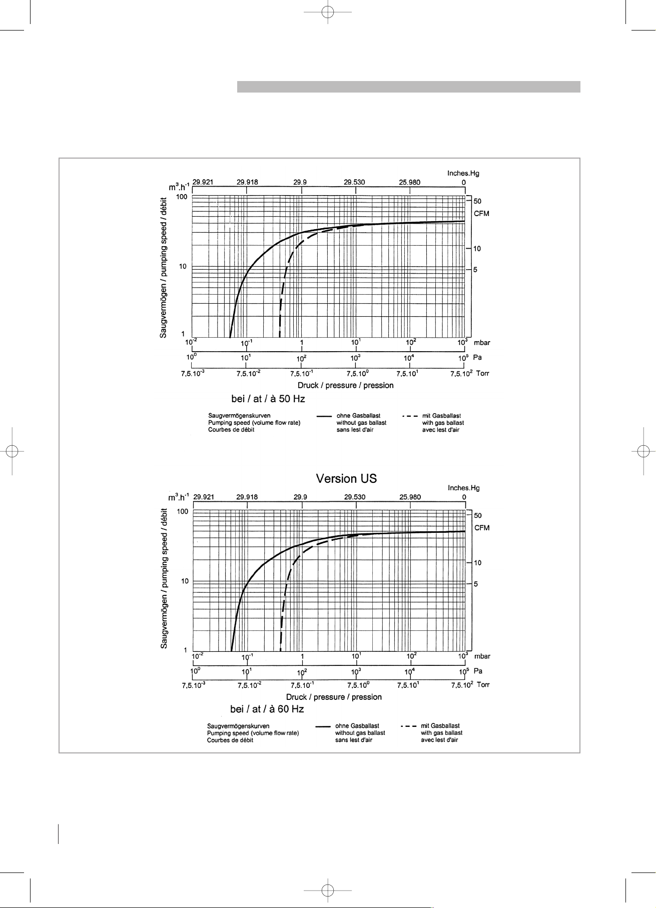
Saugvermögenskurven / Pumping speeds / Courbes de pompage
SV40 BI
Allgemeine Hinweise
General Instructions
Généralités
1
SV40BI 27/08/56 8:50 Page 8

9
GA02325_01 - 04/2005
Allgemeine Hinweise
General Instructions
Généralités
1
Ölniveauschalter Oil level switch Détecteur de niveau d’huile 711 19 110
Thermoschalter Temperature switch Sécurité thermique 9 714 32 820
Auspuffilter-Überdruckschalter Exhaust filter over pressure switch Pressostat cartouches d’échappement 9 714 25 890
Auspuffilter- Überwachungsmanometer Exhaust filter over pressure manometer Contrôleur cartouches d’échappement 95 194
Ölablasshahn Oil drain tap Robinet de vidange d’huile 711 30 114
1.5. Zubehör
Für das Zubehör verweisen wir auf den
LEYBOLD VACUUM Gesamtkatalog Kapitel
C01 und C13
1.5. Accessories
For the accessories, please refer to the
LEYBOLD VACUUM General Catalogue
chapters C01 and C13.
1.5. Accessoires
Pour les accessoires, merci de consulter le
Catalogue Général LEYBOLD VACUUM
chapitres C01 et C13.
1.6. Transport und Verpackung
Die SOGEVAC Vakuumpumpen werden in unserem Werk auf Funktion überprüft und verpackt.
Achten Sie bei der Annahme der Pumpe auf
Transportschäden.
Das Verpackungsmaterial ist nach den geltenden Bestimmungen zu entsorgen, bzw.
wiederzuverwenden.
Diese Betriebsanleitung ist Bestandteil der Lieferung.
Die Anschlüsse sind mit Kunststoff-Schutzkappen, bzw. Klebefolie verschlossen. Diese
Schutzkappen und Klebefolien müssen vor
dem Einschalten der Pumpe abgezogen werden.
Das nötige Öl wird in einem Kanister mit der
Pumpe mitgeliefert.
1.7. Handhabung und
Lagerung
1.7.1. Handhabung:
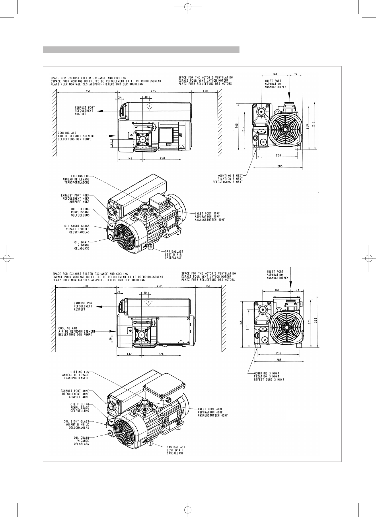
Abmessungen gem Zeichnung in Abschnitt
1.4.
Pumpen mit Ölfüllung müssen in waagrechter
Position transportiert werden um das Auslaufen von Öl zu verhindern. Der Neigungswinkel
darf 10° nicht übersteigen. Vermeiden Sie
andere Positionen beim Transport.
1.7.2. Lagerung:
Für einen längeren Stillstand versetzen Sie die
Pumpe wieder in ihren Ursprungszustand
(Ein- und Auslassöffnungen mit
Transportverschlüssen versehen, neues Öl)
und lagern Sie diese an einem trockenen Ort
bei Raumtemperatur ein. nach einer lagerung
von mehr als 1 Jahr ist eine Revision
notwendig (bitte den LEYBOLD VACUUM
Service ansprechen).
1.8. Schmierölsorten
Die SOGEVAC SV40 BI Pumpen sind für einen
Betrieb mit Mineralölen für Vakuumpumpen,
mit schwacher Viskosität nach ISO-Klasse
VG 32 vorgesehen. Das GS32-Öl von
LEYBOLD VACUUM entspricht diesen
Vorschriften.
1.6. Transport and Packing
SOGEVAC vacuum pumps pass a rigorous
operating test in our factory and are packed to
avoid transport damages.
Please check packing on delivery for transport
damages.
Packing materials should be disposed off
according to local environmental laws or reused.
These operating instructions are part of the
consignment.
The connection ports are blanked off by plastic protective caps or self-adhesives. Take
these caps or self-adhesives away before turning on the pump.
The necessary oil is supplied in a can beside
the pump.
1.7. Mounting orientation and
storage
1.7.1. Mounting orientation :
See required space on chart in paragraph 1.4.
Pumps which have been filled with operating
oil must only be moved in the upright position
(horizontally). Otherwise oil may escape. The
angle of slope may not be over 10° max. Avoid
any other orientations while moving the pump.
1.7.2. Storage :
Before stocking the pump for a long time put it
back in its original condition (blank off inlet and
exhaust ports with the shipping seals, drain the
oil sump) and store the pump in a dry place at
room temperature. A storage period
exceeding one year requires a pump
maintenance. Please contact LEYBOLD
VACUUM’s customer service.
1.8. Lubricants
The SOGEVAC SV40 BI pumps should be run
with mineral oils for vacuum pumps with low
viscosity according to ISO category VG32. The
LEYBOLD VACUUM oil GS32 corresponds to
these prescriptions.
1.6. Transport et emballage
Les pompes à vide à palettes SOGEVAC sont
testées et contrôlées dans notre usine avant
d’être emballées.
Veuillez vérifier lors de la réception que l’emballage n’a pas subi de dommage pendant le
transport.
Les matériaux d’emballage doivent être éliminés selon les lois en vigueur ou doivent être
réutilisés.
Ce manuel fait partie de notre envoi.
Les orifices de raccordement sont munis de
capuchons protecteurs en matière plastique
ou d’autocollants. Enlever ces capuchons ou
ces autocollants avant la mise en service de la
pompe.
La charge d’huile est livrée dans un bidon à
côté de la pompe dans l’emballage.
1.7. Manutention et stockage
1.7.1. Manutention :
Se reporter au plan d’encombrement paragraphe 1.4.
Les pompes avec le plein de lubrifiant doivent
être transportées en position horizontale pour
éviter la perte d’huile. L’angle d’inclinaison ne
doit pas dépasser 10° maxi. Eviter toute autre
position pendant le transport.
1.7.2. Stockage :
Pour un stockage de longue durée, remettre la
pompe dans les conditions d’origine (orifices
bouchés, pompe vidangée) et la conserver
dans un endroit sec et à température ambiante.
Un stockage de plus d’un an nécessite un
entretien de la pompe. Merci de contacter le
SAV LEYBOLD VACUUM.
1.8. Lubrifiants
Les pompes SOGEVAC SV40 BI sont prévues
pour fonctionner avec des huiles minérales
pour pompe à vide à faible viscosité de classe
ISO VG 32. L’huile LEYBOLD VACUUM GS32
remplit ces conditions.
SV40BI 27/08/56 8:50 Page 9

GS32-Öl : Verpackung Katalognummer
1 l 711 17 772
2 l 711 17 723
5 l 711 17 724
20 l 711 17 725
Der Gebrauch von anderen Schmierölsorten,
die den Anwendungen angepasst sind, ist
möglich. Bitte lassen Sie sich von uns beraten.
2. Bedienung und Betrieb
Siehe Kapitel 1.1
Die Einhaltung der Reihenfolge der hier beschriebenen Arbeitsschritte ist für eine sicherheitsgerechte und funktionssichere Inbetriebnahme unbedingt erforderlich. Die
Inbetriebnahme darf nur von geschultem
Fachpersonal durchgeführt werden.
2.1. Aufstellung
Die Pumpe muss waagrecht auf ebener Fläche
aufgestellt bzw. montiert werden. Eine spezielle Befestigung ist nicht notwendig.
Folgende Umgebungsbedingungen müssen
gegeben sein :
■ Umgebungstemperatur : 15°C bis 40°C,
■ Umgebungsdruck = Atmosphärendruck.
Um ein Überhitzung der Pumpe zu vermeiden
ist stets auf genügend Frischluftzufuhr zu
achten.
2.2. Sauganschluss
Siehe Kapitel 1.1
Der Anschluss an den Saugflansch kann über
einen vakuumdichten, flexiblen Schlauch und/
oder durch Rohrleitungen erfolgen.
Diese Rohrleitungen dürfen keine
mechanischen Spannungen auf die Pumpe
übertragen. Gegebenenfalls müssen
Kompensatoren verwendet werden.
Verengungen in den Anschlussleitungen sind
zu vermeiden, da sonst das Saugvermögen
vermindert wird. Die Nennweite der
Anschlussleitungen muss mindestens dem
Querschnitt des Saugflansches der Pumpe
entsprechen.
Beim Absaugen von feuchten Gasen oder
Dämpfen muss ein Gastballastventil vorgesehen oder geöffnet werden.
Der Ansaugdruck darf dem atm.
Druck nicht überschreiten.
GS32 Oil :Conditioning Reference
1 l 711 17 772
2 l 711 17 723
5 l 711 17 724
20 l 711 17 725
You may use other special lubricants adapted
to the applications. Please consult us.
2. Installation
See chapter 1.1
It is essential to observe the following instructions step by step to ensure safe start-up.
Start-up may only be conducted by trained
specialists.
2.1. Setting-up
The pump must be set up or mounted horizontally on a flat surface. Special mounting is not
required.
The following ambient operating environment
must be observed :
■ Ambient temperature: 15°C to 40°C (59°F to
104°F),
■ Ambient pressure = Atmospheric pressure.
In order to avoid over-heating of the pump, an
undisturbed fresh airflow to the pump is
necessary.
2.2. Inlet connection
See chapter 1.1
The inlet flange can be connected with a
vacuum-tight flexible hose and/or pipe.
The pipes should cause no stresses on the
pump’s flanges. If necessary, compensators
must be installed.
Restriction of the pipes must be avoided in order not to decrease the pumping speed of the
pump. The nominal diameter of the pipes has
to be at least the same as the diameter of
pump’s inlet flange.
When removing condensable vapours, a gas
ballast valve must be installed or opened.
The inlet pressre must be above atm.
pressure.
Huile GS32 : Conditionnement Référence
1 l 711 17 772
2 l 711 17 723
5 l 711 17 724
20 l 711 17 725
L’usage d’autres lubrifiants spéciaux adaptés
aux cas d’application est possible. Veuillez
nous consulter.
2. Installation
Voir paragraphe 1.1
Il est impératif de suivre pas à pas les recommandations suivantes pour assurer une mise
en service correcte de la pompe. Le démarrage doit être réalisé uniquement par un personnel qualifié.
2.1. Mise en place
La pompe doit être placée ou fixée sur une
surface plane horizontale. Un montage spécial
n’est pas nécessaire.
La pompe doit fonctionner dans l’environnement suivant :
■ Température ambiante : 15°C à 40 °C,
■ Pression ambiante = Pression atmosphé-
rique.
Pour éviter un échauffement anormal de la
pompe, il faut prévoir une ventilation suffisante.
2.2. Raccordement à
l’aspiration
Voir paragraphe 1.1
La bride d’aspiration doit être raccordée par
une tuyauterie souple et/ou rigide étanche au
vide.
Cette tuyauterie ne doit exercer aucune contrainte sur la bride d’aspiration ; si nécessaire,
il faut installer des compensateurs.
Il convient d’éviter les restrictions de section
qui diminuent les performances de la pompe.
Le diamètre nominal doit être au moins égal au
diamètre de la bride d’aspiration de la pompe
à vide.
Dans le cas de pompage de vapeurs condensables, prévoir un lest d’air ou l’ouvrir.
La pression à l’aspiration ne doit pas
dépasser la pression atmosphérique.
10
GA02325_01 - 04/2005
Bedienung und Betrieb
Installation
Installation
2
SV40BI 27/08/56 8:50 Page 10

2.3. Anschluss zur Auspuffseite
An der Abgasrohrleitung dürfen keine Absperrorgane oder Verengungen eingebaut werden.
Wenn eine Abgasrohrleitung installiert ist,
muss sie mindestens den gleichen
Durchmesser wie der Auspufflansch haben.
Sie sollte immer so angebaut werden, dass
kein Kondensat in die Pumpe gelangen kann
(Siphon, Gefälle).
Vorsicht: der maximale Auspuffdruck darf 1,15
bar absolut (0,15 bar relativ) nicht überschreiten und auch nicht unter Atmosphärendruck
minus 15 mbar fallen.
2.4. Öleinfüllen
Siehe Kapitel 1.1.4.
Das nötige Öl wird in einem Kanister mit der
Pumpe mitgeliefert. Um Öl einzufüllen,
Öleinfüllstopfen herausschrauben. Öl bis zur
„Max“- Markierung (am Gehäuse neben dem
Ölschauglas angebracht) einfüllen.
2.5. Elektroanschluss
Siehe Kapitel 1.1.4. und
1.1.5.
Die Elektroinstallation darf nur von einem Fachmann durchgeführt werden. Die Bestimmungen
nach IEC sind ebenso einzuhalten wie örtliche
oder länderspezifische
Vorschriften.
■ Die auf dem Motortypenschild angegebenen
Spannungs- und Frequenzangaben müssen
mit der Netzspannung und Frequenz
übereinstimmen.
■ Der Antriebsmotor ist nach IEC 60204-1
gegen Überlastung abzusichern.
■ Zur Prüfung der Drehrichtung die Pumpe
kurz ein- und ausschalten. Wenn die
Drehrichtung nicht mit der Richtung des, auf
dem Motordeckel aufgeklebten Pfeils übereinstimmt, müssen Sie zwei der drei elektrischen Phasen im Klemmenkasten umpolen.
Von der Motorenseite aus gesehen ist die
Drehrichtung nach links, entgegen dem
Uhrzeigersinn.
2.3. Connection to exhaust
side
No isolation or restricting devices should be
installed in the exhaust line of the pump. If an
exhaust line is installed, it must at least have
the same diameter as the exhaust flange. It
should be installed in a manner so that no condensate can enter the pump (siphon, slope).
Warning: The maximum exhaust pressure must
neither exceed 1.15 bar absolute
(0.15 bar relative), nor fall under atmosphere
pressure minus 15 mbar.
2.4. Oil filling
See chapter 1.1.4
The necessary oil is supplied in a can beside
the pump. To fill in the oil, unscrew the oil fill
plug and fill in until the oil level reaches the
“MAX” mark beside the oil sight glass.
2.5. Electrical connection
See chapters 1.1.4. and
1.1.5.
The electrical installation may only be conducted by a specialist. Local regulations have to
be followed.
■ Voltage and frequency mentioned on the
motor nameplate must correspond with the
supply voltage and frequency.
■ The drive motor must be protected against
overloads according to local regulations and
IEC 60204-1.
■ To check the direction of rotation of pumps,
flick pump on. If the direction of rotation is not
identical with the one indicated by the arrow
sticking on the motor hood, then inverse any
two of the 3 electrical phases in the terminal
box. Looking at the motor fan cover, the direction of rotation has to be counter-clockwise.
2.3. Raccordement à
l’échappement
Ne jamais installer des organes d’arrêt ou des
restrictions à l’échappement de la pompe. Si
une conduite d’échappement est installée, elle
doit avoir au moins le diamètre de l’échappement de la pompe. Elle doit être installée de
manière à ce qu’aucun condensat ne puisse
entrer dans la pompe (siphon, pente).
Avertissement : la pression d’échappement ne
doit pas dépasser 1,15 bar absolu (0,15 bar
relatif), ni descendre sous la pression atmosphérique diminuée de 15 mbar.
2.4. Remplissage d’huile
Voir paragraphe 1.1.4.
La charge d’huile est livrée dans un bidon à
côté de la pompe dans l’emballage. Pour faire
le plein d’huile, dévisser le bouchon de remplissage et verser l’huile jusqu’au repère
“MAX” indiqué à côté du voyant d’huile.
2.5. Raccordement électrique
Voir paragraphes 1.1.4. et
1.1.5.
L’installation électrique ne doit être effectuée
que par un spécialiste. Les réglementations
locales doivent être observés.
■ La tension et la fréquence indiquées sur la
plaque signalétique moteur doivent correspondre aux caractéristiques du réseau électrique.
■ Le moteur électrique doit être protégé contre
des surcharges conformément à IEC 60204-1.
■ Pour vérifier le sens de rotation des pompes,
actionner la pompe pendant un court instant.
Si le sens de rotation est contraire à celui indiqué par la flèche collée sur le capot moteur,
inverser deux des trois phases d’alimentation
dans la boite à bornes. Vu du côté moteur, le
sens de rotation est à gauche, sens antihoraire.
11
GA02325_01 - 04/2005
Bedienung und Betrieb
Installation
Installation
2
NL
Schaltplan für Wechselstrommotoren.
Wiring diagram for the single phase motor.
Raccordement électrique pour moteur mono.
SV40BI 27/08/56 8:50 Page 11

12
GA02325_01 - 04/2005
Bedienung und Betrieb
Installation
Installation
2
2.6. Betriebshinweise
Siehe Kapitel 1.1.1, 1.1.2, 1.1.3 und
1.2
Zum Abpumpen von kondensierbaren Gasen
und Dämpfen sollte ein Gasballastventil
eingebaut und dieses geöffnet sein.
Die Vakuumpumpe ca. 30 Minuten bei
geschlossenem Sauganschluss betreiben,
damit sie eine Betriebstemperatur von ca.
75°C erreicht. Erst danach mit dem Abpumpen
der Gase oder Dämpfe beginnen.
Nach Ende des Prozesses und vor dem
Abschalten, die Pumpe noch 30. Minuten mit
geschlossenem Sauganschluss und
geöffnetem Gasballastventil nachlaufen
lassen. Dadurch werden evtl. einkondensierte
Substanzen selbständig wierder aus dem
Pumpenöl ausgetrieben.
2.7. Abschalten
Im Ansaugstutzen der SOGEVAC Pumpen ist
ein Saugstutzenventil eingebaut, das beim will
kürlichen oder unwillkürlichen Abschalten der
Pumpe den Saugstutzen schließt. Dadurch
bleibt das Vakuum in der angeschlossenen
Apparatur erhalten und ein Ölrücksteigen in
die Apparatur wird vehindert.
Abgesehen von den Hinweisen in Kapitel 2.6.,
(Betriebshinweise) gibt es keine besonderen
Vorschriften zum Abschalten der Pumpe.
Wenn die Pumpe über eine längere Zeit hin unbenutzt bleiben soll, siehe Kapitel 1.7.
3. Wartung
Siehe Kapitel 1.1
Vor allen Wartungsarbeiten muss die Vakuum
pumpe ausgeschaltet werden und gegen versehentliches Wieder-Anschalten gesichert
sein. Wartungsarbeiten an der Pumpe dürfen
nur von entsprechend geschultem Personal
durchgeführt werden.
Der folgende Wartungsplan zeigt die üblichen
Wartungsintervalle für einen durchschnittlichen
Gebrauch der Pumpe.
Schlechte Umweltbedingungen und/oder
Abpumpen aggressiver Medien können
die Wartungsintervalle stark verkürzen.
Andererseits können günstige
Bedingungen die Wartungsintervalle
verlängern oder dazu führen, dass der 1.
Ölwechsel unnötig wird.
2.6. Operating advices
See chapters 1.1.1, 1.1.2, 1.1.3 and
1.2
When removing condensable vapours, a gas
ballast valve must be installed or opened.
The vacuum pump must be run for 30 minutes
prior to operation with the inlet connection closed, in order to reach the operating temperature of about 75°C. Only up from this operating
temperature, condensable vapours can be
transported. After use, the pump has to be left
running for an additional 30 minutes with the
inlet connection closed and open gas ballast,
to clear the oil of condensate.
2.7. Shutdown
The inlet flange of the SOGEVAC pumps contains an anti-suck back valve. It closes the inlet
flange when the pump is voluntarily or accidentally shut down, thus maintaining the
vacuum in the connected system and preventing oil from being sucked back into the system.
Except the indications in chapter 2.6 (operating advices) there are no particular precautions for the shutdown of the pump.
If the pump must be stopped for a longer period, see chapter 1.7.
3. Maintenance
See chapter 1.1
The vacuum pump must be switched off and
secured against accidental switch-on for all
maintenance jobs. All work must be done by
suitably trained personnel.
The following maintenance-schedule shows
the regular maintenance periods for an average use of the pump.
Unfavourable ambient conditions and/or
aggressive media may significantly
reduce the maintenance intervals.
On the other hand, favorable conditions
may allow longer operating periods or to
skip the first oil change.
2.6. Conseils d’utilisation
Voir paragraphes 1.1.1, 1.1.2, 1.1.3 et
1.2
Dans le cas de pompage de vapeurs condensables, un lest d’air doit être prévu ou ouvert.
La pompe à vide doit fonctionner pendant les
30 premières minutes avec la bride d’aspiration fermée, pour atteindre la température de
fonctionnement de l’ordre de 75°C. Seulement
à partir de cette température, il est possible de
pomper des vapeurs condensables. Après
l’utilisation, il convient de laisser fonctionner la
pompe 30 minutes avec la bride d’aspiration
fermée, afin d’obtenir une bonne séparation de
l’huile et des condensats.
2.7. Arrêt
La bride d’aspiration des pompes SOGEVAC
est équipée d’un clapet anti-retour. Ce clapet
se ferme à l’arrêt volontaire ou accidentel de la
pompe. Sa fermeture évite la remontée d’huile
dans l’installation sous vide.
Il n’y a pas de précaution particulière à
prendre pour l’arrêt de la pompe hormis celle
indiquée au paragraphe 2.6. (conseils d’utilisation).
Si la pompe doit être arrêtée pour une période
de temps prolongé, voir paragraphe 1.7.
3. Maintenance
Voir paragraphe 1.1
Avant tout travail d’entretien, il faut s’assurer
que la pompe a bien été arrêtée et que tout
redémarrage accidentel est impossible. Toutes
les interventions sur la pompe doivent uniquement être confiées à du personnel qualifié.
Le plan de maintenance ci-après représente
des intervalles habituels pour une utilisation
moyenne de la pompe.
Des conditions de travail sévères ou le
pompage de milieux agressifs peuvent
raccourcir fortement les intervalles.
D’autre part, des conditions favorables
peuvent rallonger les intervalles ou
éviter la première vidange.
Wartung
Maintenance
Maintenance
3
SV40BI 27/08/56 8:50 Page 12

13
GA02325_01 - 04/2005
Wartung
Maintenance
Maintenance
3
Wartungsplan
Wartungsarbeit Intervall Kapitel
Ölstand kontrollieren Täglich 3.1.
1. Ölwechsel Nach 150 3.2.
Betriebsstunden
Weitere Ölwechsel / 500 bis 1500 3.2.
Betriebsstunden
(Anwendungsabhängig)
oder 6 Monate
Auspuff-Filter wechseln Bei Ölnebel am 3.3.
Auspuff oder nach 1 Jahr
Gasballastventil Monatliche Kontrolle 3.4.
Ansaugflansch-Sieb 6 Monate 3.5.
reinigen
Saugstutzenventil 6 Monate 3.6.
kontrollieren
Ventilatordeckel reinigen 6 Monate 3.7.
Kontrolle des Elektro- 6 Monate
anschlusses (nur durch
einen Fachmann)
Zur Vereinfachung der Wartungsarbeiten
empfehlen wir, die Durchführung einzelner
Arbeitsgänge zweckmäßig miteinander zu verbinden.
3.1. Ölstand
Der Ölstand muss mindestens einmal pro Tag
überprüft werden. Der Pegel muss bei laufender Pumpe zwischen den MIN und MAX
Markierungen liegen. Falls der Ölstand unter
der Marke MIN liegt, die Pumpe ausschalten,
überprüfen (siehe Kapitel 4) und Öl nachfüllen.
3.2. Öl wechseln
Siehe Sicherheitsvorschriften Kapitel
1.1.6., 1.1.7. und 1.1.8.
Ein erster Ölwechsel muss je nach
Anwendung nach 150 Betriebsstunden
vorgenommen werden. Die folgenden
Ölwechsel müssen je nach Betriebsbedingungen (Produkte, Dämpfe,
Umgebungstemperatur...) alle 500 bis 1500
Betriebsstunden vorgenommen werden oder
mindestens alle 6 Monate.
Bei starker oder unvorhergesehener
Verschmutzung kann es notwendig sein, das
Öl bereits früher zu wechseln.
Spezielle Ölsorten können die Ölwechselintervalle verlängern.
Der Ölwechsel muss bei noch betriebswarmer
Pumpe im ausgestellten Zustand erfolgen.
Ölablaß-Stopfen lösen und das gebrauchte Öl
in einen geeigneten Behälter laufen lassen.
Sobald das Öl langsamer läuft, Ölablasstopfen schließen, die Pumpe kurz anschalten
(5 sek. max.) und sofort wieder abschalten.
Den Ölablasstopfen wieder öffnen und das
restliche Öl ablaufen lassen.
Maintenance-schedule
Maintenance job Frequency Chapter
Oil level checking Daily 3.1.
1st oil change After 150 h of operation 3.2.
Subsequent oil changes Every 500 to 1500 h 3.2.
(depending on application)
of operation or 6 months
Exhaust filter If oil mist at exhaust 3.3.
replacement or annually
Gas ballast valve Monthly checking 3.4.
Inlet flange sifter 6 months 3.5.
cleaning
Anti-suck back valve 6 months 3.6.
checking
Fan cover cleaning 6 months 3.7.
Electrical connection 6 months
checking (only by a
specialist)
In order to simplify the maintenance work we
recommend to combine several jobs.
3.1. Oil level
The oil level shall be checked at least once a
day and must be, while the pump is in operation, between the MIN and MAX marks. Should
the oil level be below the MIN mark switch off
the pump, check it (see chapter 4) and add the
required amount of oil.
3.2. Oil changing
See safety prescriptions in chapters
1.1..6., 1.1.7. and 1.1.8.
Depending of application, oil must be changed after the first 150 operat-ing hours. Further
oil changes, depending on operating conditions (products, vapours, am-bient temperature…) must be done every 500 to 1500 operating hours or at least every
6 months.
If there is considerable pollution, it could be
necessary to change the oil more frequently.
Special oils allow to extend the oil changing
period.
Oil changing must be done with a switched off
and still warm pump.
Open the oil drain plug and let run out the used
oil into an appropriate container. Refasten the
oil drain plug when oil runs slower, start up the
pump briefly (5 sec. max) and switch off immediately. Reopen the oil drain plug and drain the
rest of the oil.
Plan de maintenance
Opération à effectuer
Intervalle Paragraphe
Contrôle du niveau d’huile Chaque jour 3.1.
1ère vidange Après 150 h de service 3.2.
Autres vidanges Après 500 à 1500 h 3.2.
(selon l’application)
de service ou 6 mois
Remplacement des En cas de brouillard 3.3.
filtres d’échappement d’huile à l’échappement
ou après un an
Lest d’air Contrôle mensuel 3.4.
Nettoyage du tamis 6 mois 3.5.
d’aspiration
Contrôle du clapet 6 mois 3.6.
anti-retour
Nettoyage du capot 6 mois 3.7.
ventilateur
Raccordement électrique 6 mois
(contrôle par un
spécialiste seulement)
Pour simplifier les travaux de maintenance,
nous conseillons de grouper plusieurs
opérations.
3.1. Niveau d’huile
Le niveau d'huile doit être vérifié quotidiennement et doit se trouver, pompe en marche,
entre les repères MAX et MIN. Si le niveau
devait être inférieur au niveau MIN, arrêter et
contrôler la pompe (voir chapitre 4) et ajouter
l'huile manquante.
3.2. Vidange d’huile
Voir prescriptions de sécurité paragraphes 1.1.6., 1.1.7. et 1.1.8.
Selon les applications, une première vidange
d’huile doit être effectuée après 150 heures de
fonctionnement. Les vidanges suivantes sont à
effectuer toutes les 500 à 1500 heures en fonction des conditions d’utilisation (produits,
vapeurs, température ambiante…) ou au
moins tous les 6 mois.
Il peut s’avérer nécessaire de changer l’huile
plus rapidement en cas de pollution forte ou
accidentelle.
Des huiles spéciales peuvent rallonger la
période d’utilisation.
La vidange doit être faite pompe chaude à
l’arrêt.
Dévisser le bouchon de vidange et laisser
l’huile usagée s’écouler dans un récipient
approprié. Revisser le bouchon de vidange
quand l’huile s’écoule plus lentement, faire
tourner brièvement la pompe (5 s. max.) puis
l’arrêter aussitôt. Retirer le bouchon de vidange et vidanger l’huile restante.
SV40BI 27/08/56 8:50 Page 13

Nach Kontrolle und evt. Ersetzen des O-Rings,
Ölablasstopfen wieder schließen. Nun
Öleinfüllstopfen öffnen und neues Öl eingießen; Stopfen schließen. Wenn das Öl sehr
verschmützt ist, muss die Pumpe gespült werden
.
Dafür die Pumpe mit neuem Öl bis zum unteren Rand des Ölschauglases auffüllen und
kurz laufen lassen (nur einige Minuten),
danach nochmals einen Ölwechsel vornehmen.
3.3. Auswechseln der
Auspuff-Filter
Siehe Kapitel 1.1.6. und 1.1.8.
Wenn Ölnebel am Auspuff während des
Betriebes austritt, kann dieses ein Zeichen für
einen verstopften Auspuff-Filter sein. Erhöhte
Stromaufnahme durch den Antriebsmotor kann
ebenfalls auf einen verschmutzten Filter
zurückzuführen sein. Auspuffdeckel öffnen ,
den Filter entnehmen und ihn ersetzen.
Gleichzeitig den Zustand der Dichtung des
Auspuffdeckels überprüfen und ersetzen, falls
notwendig.
3.4. Reinigung des Gasballastventils
Siehe Sicherheitsvorschriften Kapitel
1.1.6.
Um das Gasballastventil zu reiningen, Lüfterhaube und Lüfter demontieren. Seitliche
Druckschraube und Stopfen abschrauben.
Gasballastventil mit einer zu diesem Zweck
eingeschrauben M10 Schraube herausziehen.
Membran, Sitz und RILSAN Rohr säubern. Den
Zusammenbau in ungekehrter Reihenfolge
durchführen.
3.5. Reinigung des
Ansaugflansch-Siebs
Siehe Sicherheitsvorschriften Kapitel
1.1.2., 1.1.6. und 1.1.8.
Zum Reinigen des Siebs im Ansaugflansch,
Saugflansch abmontieren und das Sieb mit
Druckluft ausblasen oder mit geeignetem
Lösungsmittel reinigen.
Before refastening the oil drain plug, control
the O-ring and if necessary replace it. Open
the oil fill plug and pour in clean oil ; refasten
the oil fill plug. The pump has to be rinsed out
if there is considerable pollution. Therefore
pour in clean oil up to the low edge of the oillevel glass, let the pump run briefly (for a few
minutes) then drain the oil again.
3.3. Exhaust filters replacement
See chapters 1.1.6. and 1.1.8.
Oil mist escaping form the exhaust during
operation indicates that the filter is probably
clogged. Increased energy intake by the motor
could also be the result of a soiled exhaust
filter. Open the exhaust hood, take out the filter
and replace it. Also check the gasket of the
exhaut flange and change it if
necessary.
3.4. Gas ballast valve
cleaning
See safety prescriptions chapter
1.1.6.
To clean the gas ballast valve, disassemble the
fan cover, and the fan. Unscrew the lateral
pressure screw, remove the plug and the gas
ballast valve by using an appropriate M10
screw screwed in the valve by pulling on the
screw. Clean the membrane, the seat and the
RILSAN tube. Reassemble in the reverse
sequence.
3.5. Inlet flange sifter cleaning
See safety prescriptions chapters
1.1.2., 1.1.6. and 1.1.8.
To clean the inlet flange sifter, disconnect the
inlet flange and clean the sifter with blast air or
an appropriate solvent.
Revisser le bouchon de vidange (contrôler et
remplacer éventuellement le joint torique).
Dévisser le bouchon de remplissage et
rajouter de l’huile neuve; revisser le bouchon.
La pompe doit être rincée lorsqu’elle est fortement souillée. Pour ce faire, remplir d’huile
neuve, seulement jusqu’au bord inférieur du
voyant, la faire tourner brièvement (quelques
minutes) puis effectuer une autre vidange.
3.3. Remplacement des
filtres d’échappement
Voir paragraphes 1.1.6. et 1.1.8.
L’apparition de brouillard d’huile à l’échappement de la pompe en service est le signe d’un
filtre colmaté. Une surcharge du moteur peut
également être la conséquence d’un filtre colmaté. Dévisser le couvercle d’échappement,
extraire la cartouche et la remplacer. Vérifier
également l’état du joint du couvercle d’échappement au remontage, le remplacer si nécessaire.
3.4. Nettoyage du lest d’air
Voir prescriptions de sécurité paragraphe 1.1.6.
Pour nettoyer le lest d’air, démonter le capot de
la turbine et retirer celle-ci. Déserrer la vis de
pression latérale, démonter le bouchon et retirer l’anti-retour à l’aide d’une vis M10 adaptée
vissée dans celui-ci. Nettoyer la membrane,
son siège et le tube RILSAN. Remonter l’ensemble dans l’ordre inverse.
3.5. Nettoyage du tamis
d’aspiration
Voir prescriptions de sécurité paragraphes 1.1.2., 1.1.6. et 1.1.8.
Pour nettoyer le tamis d’aspiration, démonter la
bride d’aspiration et nettoyer le tamis à l’air
comprimé ou avec un solvant approprié.
14
GA02325_01 - 04/2005
Wartung
Maintenance
Maintenance
3
SV40BI 27/08/56 8:50 Page 14

Wartung
Maintenance
Maintenance
3
3.6. Überprüfung des
Saugstutzenventils
Siehe Sicherheitsvorschriften Kapitel
1.1.2., 1.1.6. und 1.1.8.
Im gleichen Zeitintervall wie die Wartung des
Ansaug-flanschsiebs sollte eine Überprüfung
des Saugstutzenventils stattfinden. Wenn das
Ventil nicht sauber ist, mit geeignetem
Lösungsmittel säubern und seine Dichtseite
auf Beschädigungen überprüfen.
3.7. Reinigung des
Ventilatordeckels
Eine Verschmutzung des Ventilatordeckels
kann ein Überhitzen des Motors und der
Pumpe zur Folge haben. Deckel abmontieren
und mit Druckluft reinigen. Vor der Wiederinbetriebnahme de Pumpe, auf jeden Fall den
Deckel wieder anmontieren.
3.8. Schwimmerventil
kontrollieren
Siehe Kapitel 1.1.6.. und 1.1.8.
Mit dem Austausch der Auspuff-Filter sollte die
Sauberkeit und die Funktionsfähigkeit des
Schwimmerventils überprüft werden.
Nachdem der Auspuff Flansch demontiert ist,
Zentrierstift (Pos. 56) und Schwimmerventil
komplett (Pos. 58) herausziehen, Düse reiningen und überprüfen, dass der Schwimmer frei
um seine Achse oszillieren kann und dass das
Ventil dicht schließt. Schimmerkammer ebenfalls
reiningen. Den Zusammenbau in ungekehrter
Reihenfolge durchführen.
4. Fehlerdiagnose
Im Fall einer Panne, setzen Sie sich bitte mit
dem LEYBOLD VACUUM- Kundendienst in
Verbindung und/oder bestellen Sie unsere
Broschüre: „Pannendiagnose“.
5. Ersatzteile
Um einen sicheren Betrieb der LEYBOLD
VACUUM-Vakuumpumpe zu gewährleisten,
dürfen nur Original-Ersatzteile und Zubehör
verwendet werden. Bei Bestellung von
Ersatzteilen und Zubehör stets die
Seriennummer der Pumpe angeben. Die
Katalognummern der Teile können Sie aus der
Ersatzteil- und Zubehörtabelle entnehmen.
3.6. Anti-suck back valve
checking
See safety prescriptions chapter
s1.1.2., 1.1.6. and 1.1.8.
The anti-suck back valve should be checked
at the same time as the inlet flange sifter and if
dirty, be cleaned with an appropriate solvent.
Also check, if there is no damage on the sealing part of the valve.
3.7. Fan cover cleaning
Soiling of the fan cover may lead to overheating of the motor and the pump. Put off the
cover and clean it with blast air. Before starting
the pump again, be sure that the cover has
been reassembled.
3.8. Checking the float valve
See chapters 1.1.6. and 1.1.8
When replacing the exhaust filter, check the
cleanliness and the proper operation of the
float valve. After having disassembled the
exhaust flange, remove the centering pin (pos.
56), pull on the float valve (pos. 58), clean the
nozzle and check that the float itself oscillates
free around its axle and that the valve is tight.
Clean the float chamber of the oil casing.
Reassemble in the reverse sequence.
4. Breakdown analysis
If you have a breakdown, please contact the
LEYBOLD VACUUM service station and/or ask
us, to send you the guide: “breakdown
analysis”.
5. Spare parts
To guarantee safe operation of the LEYBOLD
VACUUM vacuum pump, only original spare
parts and accessories should be used. When
ordering spare parts and accessories, always
state pump type and serial number. You can
find part numbers in the spare parts list.
3.6. Vérification du clapet
anti-retour
Voir prescriptions de sécurité paragraphes 1.1.2., 1.1.6. et 1.1.8.
En même temps que l’opération de nettoyage
du tamis d’aspiration, vérifier la propreté du
clapet anti-retour, le nettoyer avec un solvant
approprié et vérifier l’absence de blessure de
la partie joint.
3.7. Capot ventilateur
L’encrassement du capot ventilateur peut provoquer une surchauffe du moteur et de la
pompe. Démonter le capot et le nettoyer à l’air
comprimé. Dans tous les cas remonter le
capot avant remise en service de la pompe.
3.8. Contrôle de la valve à
flotteur
Voir paragraphes 1.1.6. et 1.1.8.
Lors du remplacement du filtre d’échappement, vérifier la propreté et le bon fonctionnement de la valve à flotteur. Après avoir démonté la bride d’échappement, extraire la goupille
d’arrêt (rep 56) puis l’ensemble flotteur
(rep 58), nettoyer le gicleur et vérifier que le
flotteur oscille librement autour de son axe et
que la valve est étanche. Nettoyer le compartiment récupération d’huile du carter. Remonter
l’ensemble dans l’ordre inverse.
4. Diagnostic de pannes
En cas de panne, contacter le SAV LEYBOLD
VACUUM et/ou nous demander le guide de
diagnostic de panne.
5. Pièces détachées
Pour garantir le meilleur fonctionnement des
pompes à vide LEYBOLD VACUUM, seules
des pièces et des accessoires d’origine doivent être utilisés. En cas de commande de
pièces détachées, il faut toujours indiquer le
numéro de série de la pompe. La référence de
chaque pièce se trouve sur la liste des pièces
détachées.
15
GA02325_01 - 04/2005
Fehlerdiagnose
Breakdown analysis
Diagnostic de pannes
4
Ersatzteile
Spare parts
Pièces détachées
5
SV40BI 27/08/56 8:50 Page 15

16
GA02325_01 - 04/2005
Ersatzteile
Spare parts
Pièces détachées
5
Die Verschleißteile und die gängigsten
Ersatzteilsätze der SOGEVAC Pumpen sind
üblicherweise in den LEYBOLD VACUUM
Service Center ab Lager verfügbar. Die Liste
dieser Teile ist nachstehend aufgeführt und
auch in der Ersatzteiltabelle wo die
Zusammensetzung der Kits detailliert ist.
■ Ölfilter (abhängig von Kat. Nr)
■ Auspuff Filter
■ Öl GS 32 (Bei Einsatzt von Spezial-Ölen
beachten Sie bitte den bei der Auslieferung
der Pumpe beigefügten Hinweis oder wenden
Sie sich an LEYBOLD VACUUM).
■ Wartungssatz
■ Dichtungssatz
■ Reparatursatz
Bitte verwenden Sie bevorzug diese Kits, die
für eine optimale Instandhaltung und Wartung
der Pumpen definiert wurden. Einzelne
Ersatzteile benötigen längere Lieferzeiten.
Rücksendung zum Service
Bei Rücksendung der Pumpe zur Reparatur
zum LEYBOLD VACUUM-Service, muss das
Formular „Erklärung über Kontaminierung von
Vakuumgeräten und Komponenten“ beigelegt
werden. Auf Anfrage beim Kundendienst,
bekommen Sie es von uns zugeschickt
(Muster im Anhang der Broschüre). Pumpen,
die ohne diese Erklärung bei LEYBOLD
VACUUM eintreffen werden ohne jegliche
Prüfung kostenpflichtig zurückgeschickt.
Für den Transport müssen die Pumpe oder
Ihre Komponenten so verpackt werden, dass
sie während des Transports nicht beschädigt
werden und keine Schadstoffe aus der
Verpackung austreten können.
Consummables and main spare parts kits for
SOGEVAC pumps are usually available on
stock at LEYBOLD VACUUM’s service centers.
The list of these parts is given hereafter and in
the spare parts table where the contents of
each kit is detailed.
■ Oil filter (dependeing on the part number)
■ Exhaust demisters
■ Oil GS32 (Special oils please refer to the
specific notice of the pump or contact
LEYBOLD VACUUM).
■ Service kit
■ Set of seals
■ Repair kit
We recommend to use these kits which have
been defined to allow an optimal maintenance
or repair. Individual spare parts may need longer delivery time.
Return to LEYBOLD VACUUM service
station
If the pump has to be returned to LEYBOLD
VACUUM service station for repairing, you
have to attach the form “Declaration of
Contamination of Vacuum Equipment and
Components”. The Service of LEYBOLD
VACUUM will sent it to you on simple request
(specimen on the end of this manual).
LEYBOLD VACUUM will return to the sender’s
address any material received without this
declaration.
For the transport, the pump and its components must be packaged in such a way, that it
will not be damaged during shipping, and that
no harmful substances can escape from the
package.
Les pièces consommables et les principaux
jeux de pièces de rechange de pompes
SOGEVAC sont habituellement tenus en stock
par les centres de service après-vente
LEYBOLD VACUUM. La liste de ces pièces
figure immédiatement ci-après, et dans le
tableau des pièces de rechange où la composition des jeux est détaillée.
■ Filtre à huile (selon référence)
■ Cartouches anti-aérosols
■ Huile GS 32 (Huiles particulières, voir notice
spécifique pompe ou consulter LEYBOLD
VACUUM).
■ Kit de maintenance
■ Jeu de joints
■ Kit réparation
Nous vous recommandons l’usage de ces ensembles conçus pour permettre un entretien
ou une réparation optimale. Les autres pièces
individuelles peuvent nécessiter des délais
d’approvisionnement plus longs.
Retour en atelier
Si la pompe doit être renvoyée pour réparation
en atelier LEYBOLD VACUUM, elle doit être
accompagnée d’une “déclaration de contamination d’appareils et composants pour le vide”
que vous pouvez obtenir sur simple demande
auprès du SAV LEYBOLD VACUUM (spécimen
en fin de notice). Tout produit non accompagné d’une telle déclaration devra être retourné
à son expéditeur par LEYBOLD VACUUM.
Pour le transport, emballer les pompes ou
composants de manière à éviter leur endommagement pendant le transport et à éviter que
des produits nocifs puissent sortir de l’emballage.
SV40BI 27/08/56 8:50 Page 16

6. Informationen
Weitere Informationen senden wir Ihnen auf
Anfrage gerne zu :
Verfügbar sind :
■ Technische Beschreibung der SOGEVAC-
Vakuumpumpen
■ Technische Beschreibung der Spezialöle für
Vakuumpumpen
■ Erklärung über Kontaminierung von
Vakuumgeräten und –komponenten.
6. Information
We would be happy to supply further information as required:
Available are :
■ Technical description of the SOGEVAC
vacuum pumps
■ Technical description of special oil types for
vacuum pumps
■ Declaration of Contamination of Vacuum
Equipment and Components.
6. Informations
Sur demande, nous vous ferons parvenir avec
plaisir les documents suivants :
Sont disponibles :
■ Fiches techniques pompes à vide
SOGEVAC
■ Fiches techniques huiles spéciales pour
pompes à vide
■ Déclaration de contamination d’appareils et
composants pour le vide.
17
GA02325_01 - 04/2005
Informationen
Information
Informations
6
SV40BI 27/08/56 8:50 Page 17

18
GA02325_01 - 04/2005
Auftraggeber/Abt./Institut: Grund für die Einsendung ■■ zutreffendes bitte ankreuzen
■■ Reparatur ■■ kostenpflichtig ■■ Gewährleistung
Straße: ■■ Austausch ■■ kostenpflichtig ■■ Gewährleistung
PLZ, Ort: ■■ DKD-Kalibrierung ■■ Werkskalibrierung
Ansprechpartner: Rückgabe aus folgenden Gründen:
Telefon: Fax: ■■
Miete/Leihe ■■ zur Gutschrift ■■ gegen Austausch
Auftrags-Nr. des Auftraggebers: ■■ Austausch bereits erfolgt
A. Angaben zum Aggregat (Maschine oder Komponente) Zubehör:
Typenbezeichnung:
Artikelnummer:
Fabrikations- / Seriennummer:
Verwendetes Öl:
B. Zustand des Aggregates Nein Ja Nein Kontaminierung: Nein Ja
1. War es in Betrieb ■■ ■■ toxisch ■■ ■■
2. Entleert (Produkt/Betriebsstoffe) ■■ ■■ ätzend ■■ ■■
3. Alle Öffnungen luftdicht verschlossen! ■■ mikrobiologisch ■■ ■■
4. Gereinigt ■■ ■■ explosiv ■■ ■■
Wenn ja, mit welchem Reinigungsmittel: radioaktiv ■■ ■■
Und mit welcher Reinigungsmethode: sonst. Schadstoffe ■■ ■■
Erklärung über die Kontamination von Kompressoren, Vakuumpumpen und –Komponenten
Die Reparatur und / oder die Wartung von Kompressoren, Vakuumpumpen und –komponenten wird nur durchgeführt,
wenn eine vollständig ausgefüllte Erklärung vorliegt. Ist das nicht der Fall, kommt es zu Verzögerungen der Arbeiten.
Wenn diese Erklärung den instandzusetzenden Geräten nicht beiliegt, kann die Sendung zurückgewiesen werden.
Für jedes Aggregat ist eine eigene Erklärung abzugeben.
Diese Erklärung darf nur von autorisiertem Fachpersonal des Betreibers ausgefüllt und unterschrieben werden.
X
C. Angaben zu geförderten Stoffe (bitte unbedingt ausfüllen)
1. Mit welchen Stoffen kam das Aggregat in Berührung:
Handelsnahme und/oder chemische Bezeichnung von Betriebsmittels und geförderten Stoffen, Stoffeigenschaften z.B. nach
Sicherheitsdatenblatt ( z.B. giftig, entzündlich, ätzend, radioaktiv)
X Handelsname: Chemische Bezeichnung:
a)
b)
c)
d)
Ja Nein
2. Sind die oben aufgeführten Stoffe gesundheitsschädlich ■■ ■■
3. Gefährliche Zersetzungsprodukte bei thermischer Belastung ■■ ■■
Wenn ja, welche:
Aggregate, die mit mikrobiologischen, explosiven oder radioaktiven Stoffen kontaminiert sind, werden nur bei Nachweis
einer vorschriftsmäßigen Reinigung entgegengenommen.
D. Rechtsverbindliche Erklärung
Wir versichern, dass die Angaben in dieser Erklärung wahrheitsgemäß und vollständig sind und ich als Unterzeichner in der
Lage bin, dies zu beurteilen. Uns ist bekannt, dass wir gegenüber dem Auftragnehmer für Schäden, die durch unvoll
ständige und unrichtige Angaben entstehen, haften. Wir verpflichten uns, den Auftragnehmer von durch unvollständige oder
unrichtige Angaben entstehenden Schadenersatzansprüchen Dritter freizustellen. Uns ist bekannt, dass wir unabhängig
von dieser Erklärung gegenüber Dritten – wozu insbesondere die mit der Handhabung/Reparatur des Produktes betrauten
Mitarbeiter des Auftragnehmers gehören – direkt haften.
Name der autorisierten Person (in Druckbuchstaben):
Datum: Unterschrift: Firmenstempel:
SV40BI 27/08/56 8:50 Page 18

19
GA02325_01 - 04/2005
Customer/Dep./Institute: Reason for returning ■■ applicable please mark
■■ repair ■■ chargeable ■■ warranty
Address: ■■ exchange ■■ chargeable ■■ warranty
■■ DKD-calibration ■■ factory calibration
Person to contact: Restoring goods because of following reason:
Phone: Fax: ■■
rent/loan ■■ for credit ■■ against exchange
Order number of customer: ■■ exchange already received/arranged
A. Description of the equipment (machine or component) Ancillary equipment:
Type:
Catalogue number:
Serial number:
Type of oil used:
B. Condition of the equipment No Yes No Contamination: No Yes
1. Has the equipment been used? ■■ ■■ toxic ■■ ■■
2. Drained (Product/service fluid) ■■ ■■ corrosive ■■ ■■
3. All openings sealed airtight ■■ microbiological ■■ ■■
4. Purged ■■ ■■ explosive ■■ ■■
If yes which cleaning agent radioactive ■■ ■■
and which method of cleaning? other harmful substances ■■ ■■
Declaration of Contamination of Compressors, Vacuum Pumps and Components
The repair and / or servicing of compressors, vacuum pumps and components will be carried out only if a correctly
completed declaration has been submitted. Non-completion will result in delay. The manufacturer can refuse
to accept any equipment without a declaration.
A separate declaration has to be copleted for every single component.
X
C. Description of processed substances (Please fill in absolutely)
1. What substances have come into contact with the equipment:
Trade name and / or chemical term of service fluids and substances processed, properties of the substances
According to safety data sheet (e.g. toxic, inflammable, corrosive, radioactive)
X Tradename Chemical name:
a)
b)
c)
d)
Yes No
2. Are these substances harmful? ■■ ■■
3. Dangerous decomposition products when thermally loaded: ■■ ■■
Which:
Components contaminated by microbiological, explosive or radioactive products will not be accepted without written evidence of decontamination.
D. Legally binding declaration
I / we hereby declare that the information supplied on this form is accurate and sufficient to judge any contamination level.
Name of authorised person (block letters):
Date: Signatur of authorised person: Firm stamp:
SV40BI 27/08/56 8:50 Page 19

20
GA02325_01 - 04/2005
Société/Service/Institut : Raison du retour ■■ cocher la/les case(s) correspondante(s)
■■ réparation ■■ à payer ■■ sous garantie
Adresse : ■■ échange ■■ à payer ■■ sous garantie
■■ étalonnage DKD ■■ étalonnage usine
Personne à contacter : Matériel retourné pour les raisons suivantes :
Téléphone : Fax : ■■
prêt/location ■■ avoir ■■ contre échange
Numéro de commande du client : ■■ échange a déjà eu lieu
A. Description du matériel (machines et composants) Accessoires :
Type :
Numéro de catalogue :
Numéro de série :
Huile utilisée :
B. Etat du matériel Non Oui Non Contamination : Non Oui
1. L’appareil a-t-il été utilisé ? ■■ ■■ matières toxiques ■■ ■■
2. Vidangé (huile, lubrifiant) ■■ ■■ matières corrosives ■■ ■■
3. Ouvertures étanches à l’air ■■ matières microbiologiques ■■ ■■
4. Purgé ■■ ■■ matières explosives ■■ ■■
Quel produit /quelle méthode ? matières radioactives ■■ ■■
autres matières dangereuses ■■ ■■
Déclaration de contamination des appareils et composants pour la technique du vide
Pour raisons de sécurité et en accord avec la législation sur l’utilisation des produits chimiques dangereux, il est
impératif que vous nous retourniez ce document dûment rempli par vos soins. Dans le cas contraire, les opérations
pourront être retardées. A chaque appareil doit correspondre une déclaration de contamination.
Cette déclaration ne peut être remplie et signée que par du personnel autorisé et qualifié.
X
C. Description des substances (à remplir impérativement)
1. Substances ayant été en contact avec le matériel :
Nom du produit et/ou nom chimique des substances et produits utilisés, propriétés de ces substances.
En se référant aux fiches de données de sécurité (par exemple : substances toxiques, inflammables, corrosives, radioactives)
X Nom du produit Description chimique :
a)
b)
c)
d)
Oui Non
2. Ces substances sont-elles nocives ? ■■ ■■
3. Réaction dangereuse à la chaleur : ■■ ■■
Laquelle :
Les appareils et composants contaminés par des substances microbiologiques, explosives ou radioactives ne seront
acceptés qu’accompagnés d’une preuve écrite de décontamination.
D. Déclaration d’engagement
Je soussigné, déclare que les informations portées sur ce formulaires sont complètes et exactes. La livraison de l’appareil
contaminé et de ses composants s’effectuera conformément aux dispositions sur l’emballage, le transport et l’étiquetage
des matières dangereuses.
Nom de la personne autorisée (en lettres capitales) :
Date : Signature : Cachet :
SV40BI 27/08/56 8:50 Page 20

Ersatzteillliste
Seite
Sogevac SV40 BI …………………22 - 25
Spare parts list
page
Sogevac SV40 BI …………………22 - 25
Liste des pièces de
rechange page
Sogevac SV40 BI …………………22 - 25
21
GA02325_01 - 04/2005
Ersatzteillliste
Spare parts list
Liste des pièces de rechange
SV40BI 27/08/56 8:50 Page 21

Sogevac SV40 BI
22
GA02325_01 - 04/2005
SV40BI 27/08/56 8:50 Page 22

Pos. Stück. BENENNUNG SPECIFICATION DESIGNATION Abmessungen (mm), Werkstoff Bestell-Nr Bemerkungen
Qty Dimensions (mm), Material Ref, No, Notes
Qté Dimensions (mm), matière N° de réf Remarques
1 1 GEHÄUSEDECKEL MODULE COVER CAPOT POMPE 971424850
2 3 SCHRAUBE SCREW VIS BOMBEE PLATE HC M6X12 V3815407
3 1 SCHUTZBLECH PROTECTIVE COVER GRILLE PROTECTION POMPE 971424860
4 1 LUFTER COOLING FAN HELICE DE REFROIDISSEMENT 971424870
5 8 SCHRAUBE SCREW VIS CHC M8 X 30 Q8.8 V3811517 ●●
6 10 SCHEIBE WASHER RONDELLE W8 V3600524 ●●
7 1 RADIAL-DICHTRING RADIAL SHAFT SEAL JOINT A LEVRE 25/47X6 FKM 71421000 ●●●
8 1 LAGERDECKEL MIT GB END PLATE WITH GB FLASQUE BAGUE AVEC L.A 971431800 Incl.11,12,13,14 ●
8 1 LAGERDECKEL OHNE GB END PLATE WITHOUT GB FLASQUE BAGUE SANS L.A 971439600 ●
9 1 SCHRAUBE SCREW VIS BOUT CONIQUE HC M6X10 Q8.8 V3821415
10 1 SCHRAUBE SCREW VIS INDEXAGE M6 971424710
11 1 GASBALLASTVENTIL GAS BALLAST VALVE COMMANDE LEST D AIR 971424450 Incl. 10,11a,b,c,d,e
11a 1 O-RING O-RING JOINT TOR 4.42 X 2.62 FKM 971424460 ●
11b 2 O-RING O-RING JOINT TOR 10.77 X 2.62 FKM 71237320 ●
11c 1 FEDER SPRING RESSORT 71417990
11d 1 SCHEIBE WASHER RONDELLE M8 V3600501
11e 1 SICHERUNGSRING LOCKING RING CIRCLIPS D18 type 7000 V0800012
12 1 GASBALLAST GAS BALLAST LEST AIR 1.1m3/h 71417050 Incl. 9,11b,12a
12a 1 MEMBRANE MEMBRAN MEMBRANE D12 X 2 70SH FKM 71417060 ●
13 1 RILSAN LEITUNG RILSAN TUBE TUBE RILSAN D4/6 LG165 971424360 ●
14 1 SPANNRING CLAMPING RING COLLIER DE FIXATION DN8 971424370 ●
15 1 ANKER MIT RINGEN ROTOR WITH RINGS ROTOR BAGUE 971431810 Incl. 15a,b,c ●●
15a 1 ANKERRINGE ROTOR RING BAGUE INTERIEURE DN20/25X38.5 71421170 ●
15b 1 ANKERRINGE ROTOR RING BAGUE INTERIEURE DN32/37X20 971424900 ●
15c 1 ANKERRINGE ROTOR RING BAGUE INTERIEURE DN30/35X17 71420790 ●
16 1 SCHIEBER SATZ VON 3 VANE SET OF 3 JEU DE 3 PALETTES 971429680 ●●●
17 2 O-RING O-RING JOINT TOR 9.12 X 3.53 FKM 71417260 ●●●
18 1 O-RING O-RING JOINT TOR 110.72X3.53 FKM 71237440 ●●●
19 4 GUMMIFUSS RUBBER MOUNT AMORTISSEUR DN30 H25 71212640
20 4 SECHSKANTMUTTER HEXAGON FLANGE NUT ECROU EMBASE CRANTEE H M8 V1507500
21 1 PUMPENRING PUMP CYLINDER STATOR EQUIPE 971430360 Incl. 21a ●●
21a 2 ZENTRIERSTIFT CENTERING PIN PIED DE CENTRAGE DN8 L32 71233890
22 1 RADIAL-DICHTRING RADIAL SHAFT SEAL JOINT A LEVRE 35/52X6 FKM 71420820 ●●●
23 1 MOTOR MOTOR MOTEUR EUR 1,1KW 50HZ 230/400V, 3ϕ 71421130 Incl.23a,b,c,d,e,f,24,25
23a 1 ELEKTRISCH ROTOR ELECTRICAL ROTOR ROTOR ELECTRIQUE 971424230
23b 1 MOTOR RING MOTOR RING BAGUE ROTOR ELEC. 71421150
23c 1 SCHRAUBE SCREW VIS CHC M10 X 55 Q8.8 V3811627
23d 1 STIFTSCHRAUBE (SATZ VON 4) TIE ROD (SET OF 4) TIRANT MOTEUR (JEU DE 4) 71420560
23e 1 KLEMMENKASTEN TERMINAL BOX BOITE A BORNES 971422840
23f 1 KLEMMENBRETT TERMINAL BOARD BORNIER 971422860
23 1 MOTOR MOTOR MOTEUR USA 2 HP 60HZ 230/460V, 3ϕ 71421160 Incl.23a,b,c,d,e,24,25
23a 1 ELEKTRISCH ROTOR ELECTRICAL ROTOR ROTOR ELECTRIQUE 971424240
23b 1 MOTOR RING MOTOR RING BAGUE ROTOR ELEC. 71421140
23c 1 SCHRAUBE SCREW VIS CHC M10 X 80 Q8.8 V3811637
23d 1 STIFTSCHRAUBE (SATZ VON 4) TIE ROD (SET OF 4) TIRANT MOTEUR (JEU DE 4) 71416800
23e 1 KLEMMENKASTEN TERMINAL BOX BOITE A BORNES 971422900
24 1 LÜFTER FAN VENTILATEUR MOTEUR 71416840
25 1 LÜFTERHAUBE FAN COVER CAPOT MOTEUR 71416830
26 1 TRANSPORTLASCHE LIFTING LUG ANNEAU DE LEVAGE M8 71402970
27 1 O-RING O-RING JOINT TOR 82.14X3.53 FKM 71421340 ●
28 1 FEDER SPRING RESSORT CLAPET ASPIRATION 71212400
29 1 ANSAUGVENTIL INTAKE VALVE CLAPET ASPI. FKM 71015460 ●
30 1 ANSAUGFLANSCH INTAKE FLANGE BRIDE ASPI. EMB 71416640
31 1 O-RING O-RING JOINT TOR 50X3 FKM 71217660 ●
32 1 O-RING O-RING JOINT TOR 42X2 FKM 71237130 ●
33 1 FILTER FILTER FILTRE EMBOUTI DN45 71407290
34 4 BOLZEN LOCKING SCREW GOUJON M8-25/15J=12 Q6.8 V2100425
35 1 ANSAUGFLANSCH INTAKE FLANGE BRIDE DE RACCORDEMENT G1 _ 71416650
36 4 SCHEIBE WASHER RONDELLE Z8 V3600513
37 8 MUTTER NUT ECROU H M8 Q6 V1500501
38 2 EINSCHRAUBNIPPEL THREADED FLANGE ADAPTER ADAPTATEUR 40KF G1 1/4 MALE 71118123
23
GA/ET 02315_0
Sogevac SV40 BI
SV40BI 27/08/56 8:50 Page 23

24
GA02325_01 - 04/2005
Sogevac SV40 BI
SV40BI 27/08/56 8:50 Page 24

Pos. Stück. BENENNUNG SPECIFICATION DESIGNATION Abmessungen (mm), Werkstoff Bestell-Nr Bemerkungen
Qty Dimensions (mm), Material Ref, No, Notes
Qté Dimensions (mm), matière N° de réf Remarques
39 4 SCHRAUBE SCREW VIS CHC M8X12 Q8.8 V3811507 ●●●
40 1 VENTILANSCHLAG VALVE STOP CONTRE LAME 971439500 ●●●
41 1 VENTILPLATTE VALVE LAME 971431830 ●●●
42 1 FLACHDICHTUNG FLAT GASKET JOINT PAPIER CARTER STATOR 71420750 ●
43 1 ÖLSCHAUGLAS OIL LEVEL GLASS VOYANT HUILE G3/4 71219480 ●
44 1 ÖLRÜCKFÜHRUNGSLEITUNG OIL RECOVERY PIPE TUBE ASPIRATION HUILE 71420970
45 1 STOPFEN + O-RING PLUG + O-RING BOUCHON G _ 71256380 Incl. 45a
45a 1 O-RING O-RING JOINT TOR 27 X 2.5 FKM 71217580 ●●
46 4 SCHRAUBE SCREW VIS CHC M8X12 V3811507
47 1 AUSPUFFFLANSCH EXHAUST FLANGE BRIDE REFOULEMENT G1 _ 71420440
48 1 FEDER KOMPLETT SPRING UNIT RESSORT DE COMPRESSION ENS. 71420370 ●●
49 1 AUSPUFF-FILTER EXHAUST FILTER CARTOUCHE REFOUL. AVEC BY-PASS 71421180 ●●
50 1 ZENTRIERZIFT CENTERING PIN GOUPILLE DN2.5 971427110
51 1 FLACHDICHTUNG FLAT GASKET JOINT BRIDE REFOULEMENT FKM 71420740 ●●
52 1 SCHWIMMERKOMPLETT FLOAT COMPL. FLOTTEUR 71417210 Incl. 52a,b
52a 1 ÖLRÜCKFÜHRVENTILKLAPPE OIL RETURN VALVE SEAL CLAPET RECUPERATION HUILE 71212500 ●
52b 1 O-RING O-RING JOINT TOR 8X2 FKM 71217650 ●
53 1 STOPFEN + O-RING PLUG + O-RING BOUCHON G 1 71073040 Incl. 53a
53a 1 O-RING O-RING JOINT TOR 33 X 3.5 FKM 71217410 ●●
54 1 ÖLKASTEN OHNE ÖLFILTER OIL CASING WITHOUT OIL FILTER CARTER SANS FILTRE A HUILE EQ. 971431980 Incl. 39,54a,b,c,d
54a 2 STOPFEN + DICHTUNG PLUG + GASKET BOUCHON TRISURE + JOINT G 2 71212650 Incl. 54b
54b 2 O-RING O-RING JOINT TOR 56 X2.5 FKM 71217980 ●
54c 4 BOLZEN LOCKING SCREW M8X25 GOUJON M8 25-16/J=16 V2113426
54d 1 GITTER GRID DEFLECTEUR CARTER 971431960
DICHTUNGSSATZ SET OF SEALS JEU DE JOINTS FKM 971427640 ▲●
REPARATUR KIT REPAIR KIT KIT REPARATION 971443150 ▲
PUMPENTEIL KOMPL. MIT GB VACUUM GENERATOR WITH GB GENERATEUR DE VIDE LA 971443160 ▲
PUMPENTEIL KOMPL. OHNE GB
VACUUM GENERATOR WITHOUT GB
GENERATEUR DE VIDE SANS LA 971443170 ▲
WARTUNGSSATZ SERVICE KIT KIT DE MAINTENANCE 971427660 ▲
25
GA02325_01 - 04/2005
Sogevac SV40 BI
SV40BI 27/08/56 8:50 Page 25

26
GA02325_01 - 04/2005
Leybold Vacuum GmbH
Bonner Strasse 498
D-50968 Cologne
Phone: +49-221-347 1234
Fax: +49-221-347 1245
sales@leybold.com
Leybold Vacuum GmbH
Sales Area North/East
Branch office Berlin
Buschkrugallee 33
1. Obergeschoss
D-12359 Berlin
Phone: +49-30-435 609 0
Fax: +49-30-435 609 10
sales.berlin@leybold.com
Leybold Vacuum GmbH
Sales Area South/Southwest
Branch office Munic
Karl-Hammerschmidt-Strasse 38
D-85609 Aschheim/Dornach
Phone: +49-89-357 33 90
Fax: +49-89-357 33 933
sales.muenchen@leybold.com
service.muenchen@leybold.com
Leybold Vacuum GmbH
Sales Area West
Branch office Cologne
Emil-Hoffmann-Straße 43
D-50996 Cologne-Suerth
Phone: +49-221-347 1270
Fax: +49-221-347 1291
sales.koeln@leybold.com
Leybold Vacuum GmbH
Service Center
Emil-Hoffmann-Straße 43
D-50996 Cologne-Suerth
Phone: +49-221-347 1439
Fax: +49-221-347 1945
service@leybold.com
Leybold Vacuum GmbH
Mobile after sales service
Emil-Hoffmann-Straße 43
D-50996 Cologne-Suerth
Phone: +49-221-347 1765
Fax: +49-221-347 1944
kundendienst@leybold.com
Leybold Vacuum
Dresden GmbH
Zur Wetterwarte 50, Haus 304
D-01109 Dresden
Service:
Phone: +49-351-88 55 00
Fax: +49-351-88 55 041
info@leybold-dresden.de
www.leybold-dresden.de
Belgium
Leybold Vacuum Nederland B.V
.
Belgisch bijkantoor
Leuvensesteenweg 542-9A
B-1930 Zaventem
Sales:
Phone: +32-2-711 00 83
Fax: +32-2-720 83 38
sales.belgium@leybold.com
Service:
Phone: +32-2-711 00 8
Fax: +32-2-720 83 38
service.belgium@leybold.com
France
Leybold Vacuum France S.A.
7, Avenue du Québec
Z.A. de Courtaboeuf, B.P. 42
F-91942 Courtaboeuf Cedex
Sales and Service:
Phone: +33-1-69 82 48 00
Fax: +33-1-69 07 57 38
leybold-vacuum@leybold.fr
Leybold Vacuum France S.A.
Valence Factory
640, rue A. Bergès - B.P. 107
F-26501 Bourg-lès-Valence Cedex
Phone: +33-4-75 82 33 00
Fax: +33-4-75 82 92 69
marketing.valence@leybold.fr
Great Britain
Leybold Vacuum UK Ltd.
Waterside Way, Plough Lane
GB-London SW17 0HB
Sales:
Phone: +44-20-8971 7000
Fax: +44-20-8971 7001
sales@leybold.co.uk
Service:
Phone: +44-20-8971 7030
Fax: +44-20-8971 7003
service@leybold.co.uk
Italy
Leybold Vacuum Italia S.p.A.
8, Via Trasimeno
I-20128 Milano
Sales:
Phone: +39-02-27 22 31
Fax: +39-02-27 20 96 41
sales@leybold.it
Service:
Phone: +39-02-27 22 31
Fax: +39-02-27 20 96 41
service@leybold.it
Field Service Base
Z.I.Le Capanne
I-05021 Acquasparta (TR)
Phone: +39-0744-93 03 93
Fax: +39-0744-94 42 87
service@leybold.it
Netherlands
Leybold Vacuum Nederland B.V.
Computerweg 7
NL-3542 DP Utrecht
Sales and Service:
Phone: +31-346-58 39 99
Fax: +31-346-58 39 90
sales.netherlands@leybold.com
service.netherlands@leybold.com
Spain
Leybold Vacuum España S.A.
C/. Huelva, 7
E-08940 Cornella de Llobregat
(Barcelona)
Sales:
Phone: +34-93-666 46 16
Fax: +34-93-666 43 70
sales.spain@leybold.com
Service:
Phone: +34-93-666 49 51
Fax: +34-93-685 40 10
Sweden
Leybold Vacuum Scandinavia AB
Box 9084
SE-40092 Göteborg
Sales and Service:
Phone: +46-31-68 84 70
Fax: +46-31-68 39 39
info@leybold.se
Visiting/delivery address:
Datavägen 57B
SE-43632 Askim
Switzerland
Leybold Vacuum Schweiz AG
Leutschenbachstrasse 55
CH-8050 Zürich
Sales:
Phone: +41-1-308 40 50
Fax: +41-1-302 43 73
sales@leybold.ch
Service:
Phone: +41-1-308 40 62
Fax: +41-1-308 40 60
P.R. China
Leybold Vacuum (Tianjin)
International Trade Co., Ltd.
Beichen Economic Development
Area (BEDA), Shuanghai Road
Tianjin 300400, China
Sales and Service:
Phone: +86-22-2697 0808
Fax: +86-22-2697 4061
Fax: +86-22-2697 2017
leybold@leybold.com.cn
Leybold Vacuum (Tianjin)
Equipment Manufacturing Co., Ltd.
Beichen Economic Development
Area (BEDA), Shuanghai Road
Tianjin 300400, China
Phone: +86-22-2697 0808
Fax: +86-22-2697 4061
Fax: +86-22-2697 2017
leybold@leybold.com.cn
Leybold Vacuum (Tianjin)
International Trade Co., Ltd.
Beijing Branch:
1-908, Beijing Landmark Towers
8 North Dongsanhuan Road
Chaoyang District
Beijing 100004, China
Sales and Service:
Phone: +86-21-5064-4666
Fax: +86-21-5064-4668
leybold_sh@leybold.com.cn
Leybold Vacuum (Tianjin)
International Trade Co., Ltd.
Shanghai Branch:
Add: No. 33, 76 Futedong San
Rd., Waigaoqiao FTZ ,
Shanghai 200131, China
Sales and Service:
Phone: +86-21-5064-4666
Fax: +86-21-5064-4668
leybold_sh@leybold.com.cn
Leybold Vacuum (Tianjin)
Guangzhou Branch:
Add: G/F,#301 Building,
110 Dongguangzhuang Rd.
Tianhe District,
Guangzhou 510610, China
Sales:
Phone: +86-20-8723-7873
Phone: +86-20-8723-7597
Fax: +86-20-8723-7875
leybold_gz@leybold.com.cn
India
Leybold Vacuum India Pte Ltd.
A-125 Road No. 30
MIDC Wagle Industrial Estate
Thane(W) - 400 604
Maharashtra
India
Sales and Service:
Phone: +91-22-2581 2929
Fax: +91-22-2581 2626
ivt2004@yahoo.com
Japan
Leybold Vacuum
Japan Co., Ltd.
Head Office
Tobu A.K. Bldg. 4th Floor
23-3, Shin-Yokohama
3-chome
Kohoku-ku, Yokohama-shi
Kanagawa-ken 222-0033
Sales:
Phone: +81-45-4713330
Fax: +81-45-4713323
Leybold Vacuum
Japan Co., Ltd.
Osaka Branch Office
MURATA Bldg. 7F
2-7-53, Nihi-Miyahara
Yodogawa-ku
Osaka-shi 532-0004
Sales:
Phone: +81-6-6393-5211
Fax: +81-6-6393-5215
Leybold Vacuum
Japan Co., Ltd.
Tsukuba Technical S.C.
Tsukuba Minami Daiichi
Kogyo Danchi
21, Kasumi-no-Sato,
Ami-machi, Inashiki-gun
Ibaraki-ken, 300-0315
Service:
Phone: +81-298-89-2841
Fax: +81-298-89-2838
Korea
Leybold Vacuum Korea Ltd.
#761-4, Yulkeum-ri,
SungHwan-eup, Chonan
Choongchung-Namdo,
330-807, Korea
Sales:
Phone: +82-41-580-4421
Fax: +82-41-588-3737
Service:
Phone: +82-41-580-4419
Fax: +82-41-588-0166
Singapore
Leybold Vacuum
Singapore Pte Ltd.
No.1, International
Business Park,
B1-20B, The Synergy
Singapore 609917
Sales and Service:
Phone: +65-66652910
Fax: +65-65668202
vacuum@leyboldvac.com.sg
Taiwan
Leybold Vacuum Taiwan Ltd.
No 416-1, Sec. 3
Chung-Hsin Rd., Chu-Tung
Hsin-Chu, Taiwan, R.O.C.
Sales and Service:
Phone: +886-3-5833988
Fax: +886-3-5833999
Germany Europe Asia
USA
Leybold Vacuum USA Inc.
5700 Mellon Road
Export, PA 15632
info@leyboldvacuum.com
Sales:
Eastern & Central time zones
Phone: +1-724-327-5700
Fax: +1-724-733-1217
Pacific, Mountain,
Alaskan & Hawaiian time zones
Phone: +1-480-752-9191
Fax: +1-480-752-9494
Service:
Phone: +1-724-327-5700
Fax: +1-724-733-3799
America
Sales: +49-221-347 1234
Service: +49-221-347 1765
sales@leybold.com
service@leybold.com
@@@@@@@@e?
@@@@@@@@e?
@@h?
@@h?
@@h?
@@h?
@@h?
@@h?
@@@@@@@@e?@@@@@@@@?e@@@@@@@@e?@@@@@@@@?e@@@@@@@@e?@@@@@@@@?e@@@@@@@@e?@@@@@@@@?e@@@@@@@@e?@@@@@@@@?e@@@@@@@@e?@@@@@@@@?e@@@@@@@@e?@@@@@@@@?e@@@@@@@@e?@@@@@@@@?e@@@@@@@@e?@@@@@@@@?e@@@@@@@@e?@@@@@@@@?e@@@@@@@@e?@@@@@@@@?e@@@@@@@@e?@@@@@@@@?e@@@@@@@@e?
@@@@@@@@e?@@@@@@@@?e@@@@@@@@e?@@@@@@@@?e@@@@@@@@e?@@@@@@@@?e@@@@@@@@e?@@@@@@@@?e@@@@@@@@e?@@@@@@@@?e@@@@@@@@e?@@@@@@@@?e@@@@@@@@e?@@@@@@@@?e@@@@@@@@e?@@@@@@@@?e@@@@@@@@e?@@@@@@@@?e@@@@@@@@e?@@@@@@@@?e@@@@@@@@e?@@@@@@@@?e@@@@@@@@e?@@@@@@@@?e@@@@@@@@e?
@@@@@@@@
@@@@@@@@
@@
@@
@@
@@
@@
@@
@@
@@
@@
@@
@@
@@
@@
@@
@@
@@
@@
@@
@@
@@
@@
@@
@@
@@
@@
@@
@@
@@
@@
@@
@@
@@
@@
@@
@@
@@
@@
@@
@@
@@
@@
@@
@@
@@
@@
@@
@@
@@
@@
@@
@@
@@
@@
@@
@@
@@
@@
@@
@@
@@
@@
@@
@@
@@
@@
@@
@@
@@
@@
@@
@@
@@
@@
@@
@@
@@
@@
@@
?@@
?@@
?@@
?@@
?@@
?@@
?@@@@@@@@
?@@@@@@@@
?@@@@@@@@?e@@@@@@@@e?@@@@@@@@?e@@@@@@@@e?@@@@@@@@?e@@@@@@@@e?@@@@@@@@?e@@@@@@@@e?@@@@@@@@?e@@@@@@@@e?@@@@@@@@?e@@@@@@@@e?@@@@@@@@?e@@@@@@@@e?@@@@@@@@?e@@@@@@@@e?@@@@@@@@?e@@@@@@@@e?@@@@@@@@?e@@@@@@@@e?@@@@@@@@?e@@@@@@@@e?@@@@@@@@?e@@@@@@@@e?@@@@@@@@
?@@@@@@@@?e@@@@@@@@e?@@@@@@@@?e@@@@@@@@e?@@@@@@@@?e@@@@@@@@e?@@@@@@@@?e@@@@@@@@e?@@@@@@@@?e@@@@@@@@e?@@@@@@@@?e@@@@@@@@e?@@@@@@@@?e@@@@@@@@e?@@@@@@@@?e@@@@@@@@e?@@@@@@@@?e@@@@@@@@e?@@@@@@@@?e@@@@@@@@e?@@@@@@@@?e@@@@@@@@e?@@@@@@@@?e@@@@@@@@e?@@@@@@@@
@@g
@@g
@@g
@@g
@@g
@@g
@@@@@@@@
@@@@@@@@
@@
@@
@@
@@
@@
@@
@@
@@
@@
@@
@@
@@
@@
@@
@@
@@
@@
@@
@@
@@
@@
@@
@@
@@
@@
@@
@@
@@
@@
@@
@@
@@
@@
@@
@@
@@
@@
@@
@@
@@
@@
@@
@@
@@
@@
@@
@@
@@
@@
@@
@@
@@
@@
@@
@@
@@
@@
@@
@@
@@
@@
@@
@@
@@
@@
@@
@@
@@
@@
@@
@@
@@
Hotline
www.leybold.com
Leybold Vacuum GmbH
Bonner Strasse 498
D-50968 Cologne
Phone: +49-221 347- 0
Fax: +49-221 347-1250
info@leybold.com
SV40BI 27/08/56 8:50 Page 26

27
GA02325_01 - 04/2005
Notes
SV40BI 27/08/56 8:50 Page 27

28
GA02325_01 - 04/2005
Notes
SV40BI 27/08/56 8:50 Page 28

Leybold Vacuum GmbH
Bonner Strasse 498
D-50968 Cologne
Phone: +49-221 347- 0
Fax: +49-221 347-1250
info@leybold.com
Réalisation Sedoc - 05-05
SV40BI_couv 26/05/05 16:35 Page 2
 Loading...