

Leybold vacuum Sogevac SV65 BI FC, Sogevac SV40 B FC Operating Instructions Manual
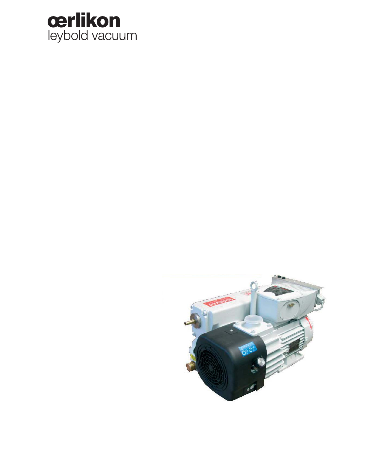
Sogevac®
SV40-65 BI FC
Single-stage, oil-sealed rotary vane pump
Operating instructions GA02341_002_A6
and spare parts list
Part-Nr:
960363V3001
960461V3001
960462V3001
960463V3001
960465V3001
960465V3002
and other variants
Document 300338321/002/A6
Original Operating Instructions

Contents
Page
Important Safety Information 3
1 Description 6
1.1 Principle of operation 6
1.2 Technical characteristics 7
1.3 Accessories 10
1.4 Lubricants 10
2 Transport and Storing 11
2.1 Transport and packaging 11
2.2 Mounting orientation 11
2.3 Storing 11
3 Installation 12
3.1 Setting up 12
3.2 Electrical connections 13
3.3 Oil filling 15
3.4 Start-up 15
4 Operation 15
4.1 Operation 15
4.2 Working in cycles in / out 16
4.3 Switching off / Shutdown 17
4.4 Conditions of use 17
4.5 Taking out of use 17
5 Maintenance 18
5.1 Safety Information 18
5.2 Maintenance Intervals 18
5.3 Oerlikon Leybold Vacuum Service 19
5.4 Maintenance Work 19
6 Troubleshooting 21
7 Spare parts 23
EC Conformance Declaration 26
Declaration of Contamination of Compressors,
Vacuum Pumps and Components 27
2
GA02341_002_A6 - 12/2013 - © Oerlikon Leybold Vacuum
Important Safety Information
Indicates procedures that must be strictly observed to prevent hazards to
persons.
Indicates procedures that must be strictly observed to prevent damage to, or
destruction of the product.
Emphasizes additional application information and other useful information
provided within these Operating Instructions.
The Oerlikon Leybold Vacuum Sogevac® has been designed for safe and
efficient operation when used properly and in accordance with these
Operating Instructions. It is the responsibility of the user to carefully
read and strictly observe all safety precautions described in this section
and throughout the Operating Instructions. The Sogevac® must only be
operated indoor. In proper condition and under the conditions described
in the Operating Instructions. If not, the protection provided by the
equipment may be impaired. It must be operated and maintained by trained
personnel only. Consult local, state, and national agencies regarding specific
requirements and regulations. Address any further safety, operation and/or
maintenance questions to our nearest office.
Failure to observe the following precautions could result in serious
personal injury!
Sogevac® pumps are not designed:
■ for pumping of dusty, aggressive, corrosive, flammable or explosive gases or
gases mixtures,
■ for pumping of oxygen or other highly reactive gases with a greater
concentration than atmospheric concentration (>20%),
■ for working in flammable, explosive or dusty environment.
For all these cases, special materials must be used. In case of doubt, please
contact Oerlikon Leybold Vacuum.
See also the limits of use indicated in the CE declaration of conformity.
Never expose part of the body to the vacuum. There is a danger of injury.
Never operate the pump with an open and thus accessible inlet. Vacuum
connections as well as oil filling and oil draining openings must not be
opened during operation of the pump.
Depending on the process involved, dangerous substances and oil may escape
from the pump. Take the necessary safety precautions !
Disconnect the unit from the power supply before starting any work.
Pump must not be operated above 2000 m sea level.
Safety Information
Warning
Caution
Note
Warning
3
GA02341_002_A6 - 12/2013 - © Oerlikon Leybold Vacuum
The Sogevac® vacuum pumps have been manufactured according to the latest
technical standards and safety regulations. If not installed properly or not used
as directed, dangerous situations or damages could occur.
It is mandatory that these operating instructions be read and understood
prior to vacuum pump installation and start-up.
The pump complies to the standard EN 61010-1-2001.
High electric voltages! When touching parts at high electric voltages, there is
the risk of suffering severe injuries by an electric shock! Covers marked with this
symbol must only be opened by trained electricians after having reliably deenergised (lockout/tagout) the equipment and waited minimum 10 minutes.
Always operate the pump with a properly connected protective earth conductor
and make sure that the motor & FC connection box are closed.
Observe the manufacturer’s information and operating instructions for the
respective frequency converter (enclosed).
Use only the OLV frequency converter for the pumps equipped with one.
After having made changes to the wiring, check the motor’s direction of rotation.
Lay the connecting lines so that these cannot be damaged. Protect the lines
against humidity and contact with fluids. Avoid thermally stressing the lines by
unfavourable laying. Provide strain relief for the connecting lines so that the
plugs and the line connectors are not subjected to excessively high mechanical
stresses.
Lay electric feed lines so that there is no risk of tripping over these.
Take appropriate precautions to insure that the pump cannot start.
If the pump has pumped hazardous gases it will be absolutely necessary to
determine the nature of the hazard involved and take the appropriate safety
precautions.
Observe all safety regulations!
Take adequate safety precautions prior to opening the intake or exhaust port.
Failure to observe the following precautions could result in damage to
the equipment!
Liquid and solid particles must not enter the pump. Install the adequate
filters, separators and/or condensers. In case of doubt consult Oerlikon
Leybold Vacuum.
The intake line of the pump must never be connected to a device with over
atmospheric pressure. Design the exhaust line so that no pressure higher
than 1,15 bar abs. (0,15 bar rel.) can occur.
Operating of the pump without oil or operating with incorrect direction of
rotation can destroy the pump.
Caution
Safety Information
Warning
Warning
4
GA02341_002_A6 - 12/2013 - © Oerlikon Leybold Vacuum
5GA02341_002_A6 - 12/2013 - © Oerlikon Leybold Vacuum
Never use discarded seals. Always assemble using new seals.
Respect the instructions concerning environment protection when discarding
used oil or exhaust filters!
The pump must be packaged in such a way that it will not be damaged
during shipping, and so that no harmful substances can escape from the
package.
We reserve the right to alter the design or any data given in these Operating
Instructions. The illustrations are not binding.
Caution : hot surface ! In normal operation, the pump surface temperature can
reach 85°C. There is a risk of burning. Switch off the pump and let it cool down
before any intervention or take appropriate precautions. It is recommended to
use an oil casing or pump touching protection at high ambient temperatures.
As a touching protection, you can use the “Noise enclosure for SV40 BI + 65 BI
FC” P/N 960331NENC. The noise enclosure is an accessory not included in the
pump delivery.
All work on a pump which is “still warm from operation” should be done only
whilst wearing protective gloves.
Handle the pump only while vented and after having let it cool down.
Never remove the oil-fill or oil-drain plugs while the pump is running. There
exists the risk of suffering burns. Always wear protective gloves and protective
goggles also for protection against the oil.
Some pumps use perfluoropolyether (PFPE) as lubricant.
When handling PFPE you should observe the following:
During thermal decomposition at temperatures over 290 °C toxic and corrosive
gases are released. This is not likely to happen in a Sogevac® pump. When
handling PFPE keep it way from open fires. Do not smoke with PFPE on your
fingers.
Touch the inner sections of the pumps only while wearing clean gloves, and use
clean tools; do the necessary work in clean and dry rooms.
Do not allow the ingestion of any objects (screws, welding beads, nuts, washers,
pieces of wire, fittings etc.) through the intake port of the pump.
Objects falling into the pump can cause severe damage.
Note
Caution
Safety Information
Caution
Warning

6 GA02341_002_A6 - 12/2013 - © Oerlikon Leybold Vacuum
1 Description
Sogevac® pumps are designed for pumping of inert gases in the range of rough
vacuum, between atmospheric pressure and ultimate pressure of the pump.
When removing condensable vapours, periodic opening of the gas ballast valve
is required.
1.1 Principle of operation
The Sogevac® pumps are single-stage oil-sealed rotary vane vacuum pumps.
The rotor, having three slots in which the vanes are sliding, is eccentrically
installed in a pump cylinder (stator).
The vanes separate the interior space into 3 chambers. The volume of these
chambers varies with the rotation of the rotor.
The gas sucked into the inlet chamber is compressed and then pushed out at
the exhaust valve.
The oil injected in the inlet chamber guarantees the air-tightness, the
lubrication and cooling of the pump. It is dragged off by the compressed
gases and roughly separated by gravity when entering in the oil sump. A fine
separation is then operated in the exhaust filter. An internal transfer pushes the
collected oil back into the vacuum generator, the transfer is operated by a float
valve to avoid atmospheric air coming from the oil casing to the inlet of the
pump when no oil is present in the recovery system.
The oil circulation functions by differential pressures.
The pumps are equipped with a gas ballast valve for pumping condensable
vapours.
The anti suckback valve at the inlet flange avoids oil coming back into the
inlet line when the pump is stopped. This is valid for working pressures below
100 mbar and under the condition that the valve is kept clean and in good
condition. The anti suck-back valve is not a safety valve. If oil back flowing is to
be avoided by all means, it is necessary to mount a separate safety valve on the
pump inlet.
Some variants are equipped with a frequency converter giving a constant
pumping speed independently of the mains frequency and regulating
the pump power consumption. At high inlet pressures, the pump speed is
decreased.
Description
7GA02341_002_A6 - 12/2013 - © Oerlikon Leybold Vacuum
Description
The pump speed can be reduced to 900 rpm (idle mode) to reduce the power
consumption w/o loss of end pressure on some pump variants. In this idle
mode, the pump inlet pressure must remain below 10 mbar.
Information to user
The user's manual or instruction manual for an intentional or unintentional
radiator shall caution the user that changes or modifications not expressly
approved by the party responsible for compliance could void the user's
authority to operate the equipment.
Note : This equipment has been tested and found to comply with the limits
for a Class A digital device, pursuant to part 15 of the FCC Rules. These limits
are designed to provide reasonable protection against harmful interference
when the equipment is operated in a commercial environment. This equipment
generates, uses, and can radiate radio frequency energy and, if not installed and
used in accordance with the instruction manual, may cause harmful interference
to radio communications Operation of this equipment in a residential area is
likely to cause harmful interference in which case the user will be required to
correct the interference at his own expense.
This product has been tested to the requirements of CAN/CSA-C22.2 No. 610101, second edition, including Amendment 1, or a later version of the same
standard incorporating the same level of testing requirements
1.2 Technical characteristics
SV40 B FC
Technical data 50 Hz & 60 Hz
Nominal pumping speed m3/h ≥ 53
Pumping speed (according to PNEUROP) m
3
/h à 2 mbar ≥ 36
Ultimate partial pressure without gas ballast mbar ≤ 0,2
Ultimate total pressure with small gas ballast mbar ≤ 1,0
Water vap our tolera nce:
■ with small gas ballast approx. mbar 10
Water vap our tolera ble loa d:
■ with small gas ballast approx. kg.h
-1
0,34
Noise level (according to DIN 46 635) dB (A) ≤ 59
Motor power - Rated rotational speed kW - min
-1
1,6-1800
Mains voltage (+/- 10 %) AC ~ V 200
... 240
Protection - Insulation
1)
IP 20 - F
Leak rate mbar.I.s
-1
<1 x 10⁻³
Ambient temperature °C 18 ... 40
See pump nameplate for further data.
1)
Given by power & interface connections.
16AT 500 A @ 250 VAC

8 GA02341_002_A6 - 12/2013 - © Oerlikon Leybold Vacuum
SV65 BI FC
Technical data 50 Hz & 60 Hz
Nominal pumping speed m3/h 71
Pumping speed (Norme PNEUROP) m
3
/h à 2 mbar ≥ 50
Ultimate partial pressure without gas ballast mbar ≤ 0,2
Ultimate total pressure with small gas ballast mbar ≤ 1,0
Water vap our tolera nce:
■ with small gas ballast approx. mbar 10
Water vap our tolera ble loa d:
■ with small gas ballast approx. kg.h
-1
0,41
Noise level (Norme DIN 46 635) dB (A) ≤ 60
Motor power - Rated rotational speed kW - min
-1
1,5-1800
Mains voltage (+/- 10 %) AC ~ V 200
... 240
Protection - Insulation
1)
IP 20 - F
Leak rate mbar.I.s
-1
<1 x 10⁻³
Ambient temperature °C 18 ... 40
See pump nameplate for further data.
1)
Given by power & interface connections.
Description
9GA02341_002_A6 - 12/2013 - © Oerlikon Leybold Vacuum
Description
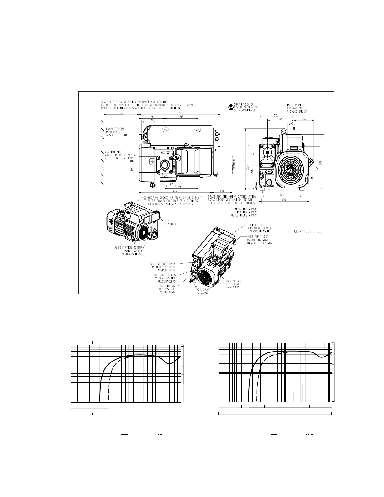
SV40 BI FC & SV65 BI FC
10
-
1
1 10
1102103
10
1
10
3104105
10
2
mbar
Pa
29.918 29.530 25.980 0 29.9
Inches.Hg
Druck / pressure / pression
Saugvermögen / pumping speed / débit
bei / at / à 50 & 60 Hz
10
50
5
CFM
Saugvermögenskurven ohne Gasballast mit Gasballast
Pumping speed (volume flow rate) without gas ballast with gas ballast
Courbes de débit sans lest d'air avec lest d'air
m3.h
-
1
100
10
1
29.921
10
-
2
10
0
Torr
7,5.10
-
3
7,5.10
-
2
7,5.10
-
1
7,5.10
0
7,5.10
1
7,5.10
2
10
-
1
1 10
1102103
10
1
10
3104105
10
2
mbar
Pa
29.918 29.530 25.980 0 29.9
Inches.Hg
Druck / pressure / pression
Saugvermögen / pumping speed / débit
bei / at / à 50 & 60 Hz
10
50
5
CFM
Saugvermögenskurven ohne Gasballast mit Gasballast
Pumping speed (volume flow rate) without gas ballast with gas ballast
Courbes de débit sans lest d'air avec lest d'air
m3.h
-
1
100
10
1
29.921
10
-
2
10
0
Torr
7,5.10
-
3
7,5.10
-
2
7,5.10
-
1
7,5.1007,5.10
1
7,5.10
2
1 Pa = 10
-2
mbar
1 Torr = 1,33 mbar
SV40 BI FC SV65 BI FC
 Loading...